JM20说明书
Kramer AFM-20DSP 产品快速入门指南说明书
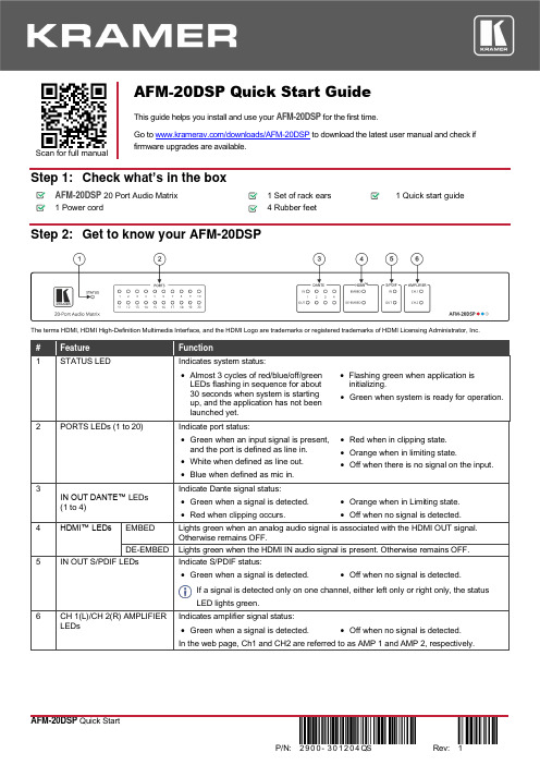
Scan for full manual AFM-20DSP Quick Start GuideThis guide helps you install and use your AFM-20DSP for the first time.Go to /downloads/AFM-20DSP to download the latest user manual and check if firmware upgrades are available.Step 1: Check what’s in the boxAFM-20DSP20 Port Audio Matrix 1 Set of rack ears1 Quick start guide1 Power cord4 Rubber feetStep 2: Get to know your AFM-20DSPThe terms HDMI, HDMI High-Definition Multimedia Interface, and the HDMI Logo are trademarks or registered trademarks of HDMI Licensing Administrator, Inc.•Green when a signal is detected. •Off when no signal is detected.If a signal is detected only on one channel, either left only or right only, the statusLED lights green.Indicates amplifier signal status:Step 3: Mount AFM-20DSPTo rack mount the machine, attach both rack ears (by removing the screws from each side of the machine and replacing those screws through the rack ears) or place the machine on a table.• Ensure that the environment (e.g., maximum ambient temperature &air flow) is compatible for the device. • Avoid uneven mechanical loading.• Appropriate consideration of equipment nameplate ratings should be used for avoiding overloading of the circuits.• Reliable earthing of rack-mounted equipment should be maintained.Step 4: Connect the inputs and outputsAlways switch OFF the power on each device before connecting it to your AFM-20DSP .For optimum range and performance use the recommended Kramer cables available at/product/AFM-20DSP . Using third-party cables may cause damage!Step 5: Connect the powerConnect the power cord to AFM-20DSP and plug it into the mains electricity.Safety Instructions (See for updated safety information)Caution:• There are no operator serviceable parts inside the unit. Warning:• Use only the power cord that is supplied with the unit.• Disconnect the power and unplug the unit from the wall before installing.• Do not open the unit. High voltages can cause electrical shock! Servicing by qualified personnel only.• To ensure continuous risk protection, replace fuses only according to the rating specified on the product label which located on the bottom of the unit.Step 6: Operate the AFM-20DSPOperate AFM-20DSP via:• Embedded web pages via the Ethernet. • RS-232 serial commandstransmitted by a touch screen system, PC, or other serial controller.Using the embedded web pagesTo route an input to an output / outputs:In the DSP Matrix page, click the lower area of cross-point buttons to connect an audio input (analog, Dante, HDMI audio signal, S/PDIF or a signal generator) to one or several outputs (analog, Dante, HDMI or S/PDIF). The button lights green. Click the dB area on a cross-point button to set the output volume.To process an input/output signal:In the DSP Main page, process each input and output audio signal and view the routing state of the matrix. Click AMP to select the amplifier audio signal.To mix the audio signals:In the DSP Mixer page, control the audio level (or mute) each input/output, define an analog input as line or mic, and so on. You can also store/recall snapshots of the current mixing setting.To define the audio and video settings:In the A/V Settings page, select the I/O port configuration, save and load system presets, define Dante and Ethernet parameters and set HDMI labels and input pattern.To define device parameters:In the Settings page, enter the device name, Ethernet settings, firmware upgrade, date and time settings or perform a factory reset.。
主要施工机械设备投入计划

主要施工机械设备投入计划本工程施工所用垂直运输设备、混凝土输送泵等大中型机械设备将由我公司内部配置,个别无法调配或企业并不拥有,则考虑社会力量解决;混凝土的搅拌、运输由我公司混凝土搅拌站完成,砌筑抹灰等建筑砂浆以采用预拌砂浆为主。
根据施工进度计划、施工段划分、施工工艺、施工经验和现有可调配机械,编制机械设备供应计划以保证施工生产顺利进行。
第一节、垂直运输机械第一小节、塔吊的配备第一条、塔吊的选择我公司针对本工程采用1台TC6013型塔吊及若干汽车吊。
对本工程新建建筑的施工面形成90%以上覆盖。
第二条、多塔作业安全措施加强对各种机械设备安全管理,建立健全机械设备的使用和保养制度,使各种机械设备经常处于良好的使用状态,具有良好的机械性能。
塔吊安全操作措施:多塔作业时,任何相临的塔吊两塔之间的任何接近部位(包括吊重物)距离不得小于2m。
塔吊钩头的所吊材料必须符合塔吊安全限荷。
塔吊在工作时不得做360°回转。
塔吊停止工作时,必须拉闸断电,并将塔吊钩头进行固定。
指挥人员及起重司机的职责:指挥人员的职责:指挥人员对所指定的起重机械,必须熟悉其机械性能后方能指挥。
使用标准指挥信号与起重机司机联系。
指挥人员的作用就是使司机按指挥信号的要求操作,把负载或空钩向其目的地运行。
不能干涉起重机司机对手柄或旋组的选择。
负责负载的重量计算和绳索的正确选择。
在负载运行时,指挥人员应负责监视并随时引导,以对可能出现的事故采取必要的防范措施。
当负载到达目的地或指定区域时,指挥人员在发出吊钩或负载下降信号前,应保证降落地点的人身、设备安全。
指挥人员的指挥位置:保证与起重机司机之间视线清楚。
在所指定的区域内,始终能清楚地看到负载。
例当负载向指挥人员靠近时,不受威胁。
当指挥人员不能同时看见起重机司机和负载时,其位置应站到能看见他指挥的司机的一侧。
根据工作需要,也可临时增设辅助指挥人员,以通知负载的位置。
起重机司机的职责:把指挥人员发出的信号变成起重机械的运动,完成吊运任务。
捷远梦之梦20L微波炉用户指南说明书

SAVE THESE INSTRUCTIONS CAREFULLYRead these instructions carefully before using your microwave oven,and keep it carefully.If you follow the instructions, your oven will provide you with many years of good service.MODEL:BM20LNB /BM20LIXSpecifications(a) Do not attempt to operate this oven with the door open since this canresult in harmful exposure to microwave energy. It is important not to break or tamper with the safety interlocks.(b) Do not place any object between the oven front face and the door or allow soil or cleaner residue to accumulate on sealing surfaces.(c) WARNING: If the door or door seals are damaged, the oven must not be operated until it has been repaired by a competent person.ADDENDUMIf the apparatus is not maintained in a good state of cleanliness, its surface could be degraded and affect the lifespan of the apparatus and lead to a dangerous situation.PRECAUTIONS TO AVOID POSSIBLE EXPOSURE TO EXCESSIVE MICROWAVE ENERGY230V~50Hz 1250W 800W 20L 245mm Model:Rated Voltage:Rated Input Power(Microwave):Rated Output Power(Microwave):Oven Capacity:Turntable Diameter:External Dimensions:Net Weight:M Approx 1.kg 594X344X388mmB 20LNB/BM20LIX 45To reduce the risk of fire, electric shock, injury to persons or exposure to excessive microwave oven energy when using your appliance, follow basic precautions, including the following:1. Warning: Liquids and other foods must not be heated in sealed containers since they are liable to explode.2. Warning: It is hazardous for anyone other than a competent person to carry out any service or repair operation that involves the removal of a cover which gives protection against exposure to microwave energy.3. This appliance can be used by children aged from 8 years and above and persons with reduced physical, sensory or mental capabilities or lack of experience and knowledge if they have been given supervision or instruction concerning use of the appliance in a safe way and understand the hazards involved.Children shall not play with the appliance.Cleaning and user maintenance shall not be made by children unless they are older than 8 and supervised.4. Keep the appliance and its cord out of reach of children less than 8 years.5. Only use utensils that are suitable for use in microwave6. The oven should be cleaned regularly and any food deposits should be removed.7. Read and follow the specific:"PRECAUTIONS TO AVOID POSSIBLE EXPOSURE TO EXCESSIVE MICROWAVE ENERGY".8. When heating food in plastic or paper containers,IMPORTANT SAFETY INSTRUCTIONS WARNING oven .skeep an eye on the oven due to the possibility of ignition.9. If smoke is emitted, switch off or unplug the appliance and keep the door closed in order to stifle any flames.10. Do not overcook food.11. Do not use the oven cavity for storage purposes.Do not store items, such as bread, cookies, etc. inside the oven.12. Remove wire twist-ties and metal handles frompaper or plastic containers/bags before placing them in the oven.13. Install or locate this oven only in accordance with the installation instructions provided.14. Eggs in the shell and whole hard-boiled eggs should not be heated in microwave ovens since they may explode, even after microwave heating has ended.15.This appliance is intended to be used in household and similar applications such as:-staff kitchen areas in shops, offices and other working environments;-by clients in hotels, motels and other residential type environments;-farm houses;-bed and breakfast type environments.16. If the supply cord is damaged, it must be replaced by the manufacturer, its service agent or similarly qualified persons in order to avoid a hazard.17. Do not store or use this appliance outdoors.18. Do not use this oven near water, in a wet basementor near a swimming pool.19. The temperature of accessible surfaces may be high when the appliance is operating. The surfaces are liable to get hot during use. Keep cord away from heatedsurface, and do not cover any vents on the oven.20. Do not let cord hang over edge of table or counter.21. Failure to maintain the oven in a clean conditioncould lead to deterioration of the surface that could adversely affect the life of the appliance and possibly result in a hazardous situation.22.The contents of feeding bottles and baby food jarsshall be stirred or shaken and the temperature checked before consumption, in order to avoid burns.23. Microwave heating of beverages can result indelayed eruptive boiling, therefore care must be taken when handling the container.24.The appliance is not intended for use by persons (including children) with reduced physical, sensory or mental capabilities, or lack of experience and knowledge, unless they have been given supervision or instruction concerning use of the appliance by a person responsible for their safety.25.Children should be supervised to ensure that they do not play with the appliance.26.The appliances are not intended to be operated by means of an external timer or separate remote-control system.27. Accessible parts may become hot during use.Young children should be kept away.28.Steam cleaner is not to be used.29.During use the appliance becomes hot. Care shouldbe taken to avoid touching heating elements inside the oven.30.Only use the temperature probe recommended forthis oven.(for ovens provided with a facility to use atemperature-sensing probe.)31.WARNING: The appliance and its accessible parts become hot during use. Care should be taken to avoid touching heating elements. Children less than 8 years of age shall be kept away unless continuously supervised.32.The microwave oven must be operated with the decorative door open.(for ovens with a decorative door.)33.Surface of a storage cabinet can get hot.34.The microwave oven is intended for heating food and beverages.Drying of food or clothing and heating of warming pads,slippers,sponges,damp cloth and similar may lead to risk of injury,ignition or fire.READ CAREFULLY AND KEEP FOR FUTURE REFERENCETo Reduce the Risk of Injury to Persons Grounding InstallationDANGERElectric Shock Hazard Touching some of the internal components can cause serious personal injury or death. Do not disassemble this appliance. WARNINGElectric Shock Hazard Improper use of the grounding can result in electric shock.Do not plug into an outlet until appliance is properly installed and grounded.This appliance must be grounded. In the event ofan electrical short circuit, grounding reduces therisk of electric shock by providing an escape wirefor the electric current.This appliance is equipped with a cord having a grounding wire witha grounding plug. Theplug must be plugged into an outlet that is properly installed and grounded.Consult a qualified electrician or servicemanif the grounding instructions are not completely understood or if doubt exists as to whether the appliance is properly grounded.If it is necessary to use an extension cord, use onlya 3-wire1. A short power-supply cordis provided to reduce the risks resulting from becoming entangled in or tripping over a longer cord.cord is used:1)The marked electrical rating of the cord set or extension cord should be at least as great as the electrical rating of the appliance.2)The extension cord must bea grounding-type 3-wire cord.3)The long cord should be arranged so that it will not drape over the counter top or tabletop where it can be pulled onby children or tripped over unintentionally.cord.extension2. If a long cord set or extensionCLEANINGBe sure to unplug theappliance from thepowersupply.1. Clean the cavity of the oven after using with a slightly damp cloth.2. Clean the accessories in the usual way in soapy water.3. The door frame and seal and neighbouring parts must be cleaned carefully with a damp cloth when they are dirty.4. Do not use harsh abrasive cleaners or sharp metal scrapersto clean the oven door glass since they can scratch the surface, which may result in shattering of the glass.5. Cleaning Tip---For easier cleaning of the cavity walls that the food cooked can touch: Place half a lemon in a bowl, add 300ml (1/2 pint) water and heat on 100% microwave power for 10 minutes. Wipe the oven clean using a soft, dry cloth.UTENSILSCAUTIONPersonal Injury HazardIt is hazardous foranyone other than acompentent persontocarry out any service or repair operation that involves the removalof a cover which gives protection against exposure to microwave energy.Utensil Test:1. Fill a microwave-safe container with 1 cup of cold water (250ml) along with the utensil in question.2. Cook on maximum power for 1 minute.3. Carefully feel the utensil. If the empty utensil iswarm, do not use it for microwave cooking.4.Do not exceed 1 minute cooking time.See the instructions on "Materials you can use in microwave oven or to be avoided in microwave oven." There may be certain non-metallic utensils that are not safe to use for microwaving. If in doubt, you can test the utensil in question following the procedure below.Materials you can use in microwave ovenUtensilsRemarks Aluminum foil Shielding only. Small smooth pieces can be used to cover thin parts ofmeat or poultry to prevent overcooking. Arcing can occur if foil is tooclose to oven walls. The foil should be at least 1 inch (2.5cm) away from oven walls.Follow manufacturer’s instructions. The bottom of browning dish must beat least 3/16 inch (5mm) above the turntable. Incorrect usage may causethe turntable to break.Microwave-safe only. Follow manufacturer's instructions. Do not usecracked or chipped dishes.Always remove lid. Use only to heat food until just warm. Most glass jarsare not heat resistant and may break.Heat-resistant oven glassware only. Make sure there is no metallic trim.Do not use cracked or chipped dishes.Follow manufacturer’s instructions. Do not close with metal tie. Makeslits to allow steam to escape.Use for short–term cooking/warming only. Do not leave oven unattended while cooking.Use to cover food for reheating and absorbing fat. Use with supervisionfor a short-term cooking only.Use as a cover to prevent splattering or a wrap for steaming.Microwave-safe only. Follow the manufacturer’s instructions. Should belabeled "Microwave Safe". Some plastic containers soften, as the foodinside gets hot. "Boiling bags" and tightly closed plastic bags should beslit, pierced or vented as directed by package.Microwave-safe only. Use to cover food during cooking to retainmoisture. Do not allow plastic wrap to touch food.Thermometers Microwave-safe only (meat and candy thermometers).Wax paperUse as a cover to prevent splattering and retain moisture.Browning dish Glass jars Glassware Oven cooking bags Paper plates and cups Paper towels Parchment paper Plastic Plastic wrap Dinnerware Materials to be avoided in microwave ovenUtensilsRemarks Aluminum trayFood carton withmetal handleMetal or metal-trimmed utensilsMetal twist tiesPaper bagsPlastic foamWood Metal shields the food from microwave energy. Metal trim may cause arcing.May cause a fire in the oven.Plastic foam may melt or contaminate the liquid inside when exposed to high temperature.Wood will dry out when used in the microwave oven and may splitor crack.May cause arcing. Transfer food into microwave-safe dish.May cause arcing. Transfer food into microwave-safe dish.May cause arcing and could cause a fire in the oven.B) Turntable shaftC) Turntable ring assemblyD) Glass trayE) Observation windowF) Door assemblyG) Safety interlock systemASETTING UP YOUR OVENNames of Oven Parts and AccessoriesRemove the oven and all materials from the carton and oven cavity.Your oven comes with the following accessories:Glass tray 1Glass tray a. Never place the glass tray upside down. The glasstray should never be restricted.b. Both glass tray and turntable ring assembly mustalways be used during cooking.c. All food and containers of food are always placedon the glass tray for cooking.d.If glass tray or turntable ring assembly cracks orbreaks, contact your nearest authorized servicecenter.Turntable InstallationInstallation and connection1.This appliance is only intended for domestic use.2.This oven is intended for built-in use only. It is not intended for counter-top use or for use inside a cupboard.3. Please observe the special installation instructions.4.The appliance can be installed in a 60cm wide wall-mounted cupboard(at lease 55cm deep and 85cm off the floor).5.The appliance is fitted with a plug and must only be connected to a properly installed earthed socket.6.The mains voltage must correspond to the voltage specified on the rating plate.7.The socket must be installed and connecting cable must only be replaced by a qualified electrician. If the plug is no longer to accessible following installation, an all-pole disconnecting device must be present on the installation side with a contact gap of at lease 3mm.8.Adapters, multi-way strips and extension leads must not be used. Overloading can result in a risk of fire.The accessible surface maybe hot during operation.Please noteElectrical connectionThe oven is fitted with a plug and must only be connected to a properly installed earthed socket. The socket must only be installed and the connecting cable must only be replaced by a qualified electrician, and in accordance with the appropriate regulations.If the plug is no longer accessible following installation, an allĆpole isolating switch must be present on the installation side with a contact gap of at least 3 mm.The fitted cabinet must not have a back wall behind the appliance.Minimum installation height: 85 cm.Do not cover ventilation slots and suction holes.Note:Do not trap or bend the power cable.Installation InstructionsPlease Read the Manual Carefully Before InstallationA. Built-in furniture380+234050380+2Note:The bracket and bottom caninet template are needed when installating in installation.both sB.Prep are the cab i inetput the template on the bottom plane of cabinet.1. Read the instruction on the BOTTOM CANINET TEMPLATE ,2. Make the marks on the bottom plane of cabinet according to marks"a" of of the template3. Remove the bottom cabinet template and fix the bracket w ith screw A.BracketScrew A.Install the oven4. Install the oven to the cabinet- Make sure the back of the oven is locked by bracket.- Do not trap or kink the power cord.bracket5. Open the door, fix the oven to the cabinet wi th Screw B, at the installa tion hole. Then fix the Trim-kit plastic cover to the installation hole.Screw BInstallation HoleControl PanelOperation Instructions3) Press " ", the minute figures will flash.3) Press " " to confirm, and the screen displays "P 80".5) Press " " to start cooking .1. Clock SettingWhen the microwave oven is electrified, the LED will display "0:00", buzzer will ring once.1) Press "" twice to select clock function, the hour figures will flash.5) Press " " to finish clock setting. ":" will flash, and the time will light.Note : the step quantities for the adjustment time of the coding switch are as follow: 0---1 min : 5 seconds 1---5 min : 10 seconds 5---10 min : 30 seconds 10---30 min : 1 minute power.Note: 1) 2) During the process of clock setting, if you press " ", the oven will go back to the previous status automatically.2. Microwave Cooking" the LED will display "P100".Press " ""P30" or "P10" will display for each added press. Then press" "Example: If you want to use 80% microwave power to cook for 20 minutes, you can operate the oven as the following steps.Start/+30Sec./Confirm Kitchen Timer/Clock Start/+30Sec./Confirm Stop/Clear Start/+30Sec./ConfirmThe clock will not work if it is not set when powered.Kitchen Timer/ClockKitchen Timer/Clock Microwave3) Press " " to start defrosting.1) In waiting state, Press " " to start cooking with 100% power,each added press will increase 30 seconds cooking time up to 95 minutes.2) In microwave cooking or time defrost state, each press of" " can increase 30 seconds of cooking time. microwave power, then press " " to start cooking.Start/+30Sec./Confirm Start/+30Sec./Confirm Start/+30Sec./ConfirmStart/+30Sec./Confirm" to confirm setting.(4) When the kitchen time is reached, clock indicator will go out. The buzzer will ring 5 times. If the clock be set(24-hour system), LED will display the current time.Note: The kitchen Time is differ from 24-hour system,Kitchen Timer is a timer.3) Press " " to start defrosting.The defrost power is P30 , and it cannot be changed.Start/+30Sec./Confirm once, LED will display 00:00.3. Quick Start5. Defrost By Timefish,beverage and popcorn.4) Press " " to start cooking.Start/+30Sec./Confirm vegetable,pasta, potato,7) Press " " to start cooking, and buzzer will sound once for the first section, defrosting time counts down; buzzer will sound once again entering the second cooking. when cooking finish, buzzer sounds five times.3) Press " " once, the screen display "P100".5) Press " " to confirm, and the screen displays "P 80".At most 2 sections can be set for cooking. In multi-section cooking, if one section is defrosting, then defrosting shall be placed in the first section.Example: If you want to defrost food for 5 minutes and then cook with 80% microwave power for 7 minutes, operate it as the following:Start/+30Sec./Confirm Start/+30Sec./Confirm7. Multi-section cookingMicrowaveAuto MenuMenu Weight DisplayA-1Pizza200g 200400g 400A-2 Meat 250g250 350g 350 450g450A-3 Vegetable 200g200 300g300 400g400A-4 Pasta 50g (with water 450g) 50 100g(with water 800g) 100A-5 Potato 200g 200 400g 400 600g 600A-6 Fish 250g 250 350g 350 450g 450A-7 Beverage 1 cup (120ml) 12 cup (240ml) 23 cup (360ml) 3A-8 Popcorn 50g 50 100g 10021(1) In states of microwave cooking, press " ", be displayed for 3 seconds. After 3 seconds, the oven will turn back to the former state;(2) In cooking state, press " " to inquire the time and the time will display for 3 seconds.1Lock: In waiting state, press " " for 3 seconds, there will be a long beepdenoting entering the children-lock state and the current time will diplay if the time has been set, otherwise, the LED will display " ".Lock quitting: In locked state, press " " for 3 seconds, there will be a long "beep" denoting that the lock is released.Stop/Clear Stop/ClearKitchen Timer/ClockMicrowave 9. Inquiring Function0. Lock-out Function for Childrenthe current power willTrouble shootingAccording to Waste of Electrical and Electronic Equipmenttreated. If at any time in future you need to dispose of thisproduct please do NOT dispose of this product with householdwaste. Please send this product to WEEE collecting pointswhere available.22PN:16170000A23116。
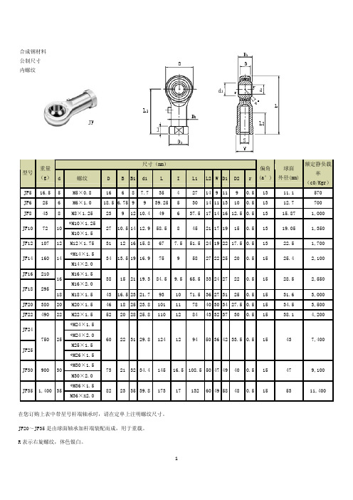
杆端轴承
JF3/16 16.5 3/16
13
570
10-32 17 6
8 7.7 35 4 26.5 14 9 11 9 0.5
11.11
0.7283 0.2657 0.3543 0.3543 1.5433 0.1969 1.1811 0.5512 0.4331 0.5118 0.3937 0.0197 0.5000
0.5
28.5
2,550
1.8110 0.7086 0.9843 0.9409 4.0551 3.1496 1.8503 0.0197
1.3582
JM3/4 340 3/4 3/4×16
15
46
18
25 23.9 103
80
47
0.5
34.5
3,550
2.0472 0.7874 1.1024 1.0157 4.4094 3.3858 2.0078 0.0197
10 71.5 36 27 31 25 0.5 15 11 78 40 30 34 27.5 0.5 15 12 84 43 32 37 30 0.5 15
28.5
31.6 34.5 38.1
2,550
3,000 3,500 4,200
60 22 31 29.8 124 12 94 50 36 42 33.5 0.5 15
0.6250
JM5/16 32 5/16 5/16×24
13
700
23
9
12 10.4 54 42.5 25
0.5
15.87
JM3/8
1.0629 0.4133 0.5512 0.5078 2.4409 1.9094 1.1417 0.0197
midea VS-MJ20TAR1 吸尘器使用说明书
MANUALDEL USUARIOASPIRADORA SIN BOLSA.arPor favor lea atentamente el manual del usuario antes de utilizar el producto.make yourself at homeVS-MJ20TAR1Por favor lea el manual cuidadosamente antes de utilizar la aspiradora y guárdelo para futuras referencias CONTENIDO1. Advertencias y precauciones de seguridad (3)2. Detalle de las partes (4)3. Instrucciones de uso (5)3.1 Ensamble de las partes antes del uso (5)4. Limpieza del recipiente para la basura (6)5. Accesorios (7)5.1 Cómo utilizar los accesorios (7)6. Mantenimiento (8)6.1 Cómo mantener correctamente la aspiradora (8)6.2 Pasos para la limpieza de los filtros (8)7. Especificaciones (9)8. Como desechar el producto (9)Garantía (11)VS-MJ20TAR1238. No almacene ni utilice la aspiradora en lugares con altas temperaturas.9. No permita que niños utilicen el electrodoméstico, ya que puede causar accidentes.10. Si siente olores o ruidos anormales, ve humo o percibe alguna falla o ruptura durante el uso, debe apagar y desconectar la aspiradora de inmediato. Luego contacte a su centro de service para que la reparen. No intente repararla usted mismo.11. Si el cable de alimentación está dañado, el mismo debe ser reemplazado por el fabricante, su agente de service o alguien con calificaciones similares para evitar daños.1. ADVERTENCIAS YPRECAUCIONES DE SEGURIDAD1. Antes del primer uso, se recomienda que lea el manual cuidadosamente y lo guarde para futuras referencias.2. Asegúrese que el recipiente de recolección de basura esté correctamente colocado.3. Compruebe que la alimentación eléctrica sea de 220-240V 50Hz.4. No aspire agua o materiales inflamables.5. No aspire materiales en combustión o cenizas.6. No utilice la aspiradora sin colocar un filtro de protección de motor.7. Por favor, cambie el filtro de polvo / HEPA inmediatamente si el mismo estuviera dañado.10245VS-MJ20TAR142. DETALLE DE LAS PARTES7- Rueda trasera.8- Perilla de control de potencia. 9- Manija.10- M anguera.11- Botón enrollacable.12- Manija del recipiente recolector de basura.1- Cepillo.2- Tubo extensor metálico.3- Recipiente de recolección de basura.4- Conector de la manguera.5- Cepillo compacto 2 en 1.6- Botón de liberación del recipiente.3. INSTRUCCIONES DE USO3.1 Ensamble de las partes antes del usoLa figura 1 muestra la conexión de la manguera en la aspiradora:- Coloque el conector de la manguera en la parte delantera de la aspiradora.- Luego insértelo en el orificio de entrada y gírelo a laderecha.- Para desmontarlo, gírelo hacia la izquierda y luego tire hacia afuera.La figura 2 muestra la conexión de la manguera y el tubo metálico de extensión:- Sujete el conector curvo del extremo de la manguera e insértelo en el extremo más grande del tubo.La figura 3 muestra la conexión del tubo con el cepillo de aspiración:- Coloque el tubo metálico dentro del tubo del cepillo, presione y gírelo para trabarlo.La figura 4 muestra cómo desenrollar y enrollar el cable de alimentación:- Tire del cable de alimentación hasta alcanzar la extensión deseada. Deténgase cuando aparezca la marca amarilla. Asegúrese de que la marca roja no quede visible.- Cuando haya terminado de aspirar, primero desconecte la alimentación tirando del enchufe (nunca tire del cable) y l uego presione el botón para enrollar el cable, hasta que el mismo esté completamente dentro de la máquina.La figura 5 muestra el botón de encendido- Coloque el enchufe de la aspiradora en el tomacorrientes y presione el botón de encendido para poner la aspiradora en funcionamiento.La figura 6 muestra la perilla para regular la potencia. - Gire la perilla en sentido horario para incrementar lapotencia.Figura 1Figura 2Figura 4 Figura 5 Figura 65VS-MJ20TAR164. LIMPIEZA DEL RECIPIENTE PARA LA BASURAPasos para la limpieza del recipiente para la basura:1. Comomuestra la figura 7, sostenga el recipiente para la basura por el mango y presione el botón de liberación.2. Retire el recipiente para la basura de la aspira-dora, según muestra la figura 8.3. Quite la tapa del recipiente como muestra la figura 9.4. Descargue el recipiente en el cesto de basura como muestra la figura 10.5. Una vez que haya vaciado el recipiente, coló-quele la tapa y vuelva a colocar el mismo en la aspiradora para continuar utilizándola.Figura 7Figura 8Figura 105. ACCESORIOS5.1 Cómo utilizar los accesorios:1. Puede utilizar el cepillo compacto (figura 11) en rincones y aberturas.2. Como muestra la figura 12, utilice el lado con cerdasdel cepillo compacto girándolo como indica la flecha, para limpiar el sofá, cortinas y el polvo acumulado en adornos.3. Como muestra la figura 13, pise el pedal del cepillo de aspiración para que las cerdas queden hacia afuera y pueda limpiar el piso (cerámicos, parquet, etc.).4. Como muestra la figura 14, pise el pedal del cepillo de aspiración nuevamente para que las cerdas queden hacia adentro y pueda limpiar la alfombra.Figura 11 Figura 12 Figura 13 Figura 1476. MANTENIMIENTO6.1 Cómo mantener correctamente la aspiradora: 1. El filtro debe limpiarse como mínimo dos veces al año. Cada vez que note suciedad acumulada en el mismo, deberá limpiarlo.2. Coloque el filtro correctamente antes de encender la aspiradora.3. El filtro no puede lavarse en lavarropas ni secarse ensecadora.4. Si utiliza el filtro húmedo, podría reducir la potencia de aspiración o dañar el motor.6.2 Pasos para la limpieza de los filtros:1. Como muestra la figura 15, presione la traba de la rejilla de salida para abrirla.2. Quite la rejilla y el filtro exterior, de acuerdo con la figura 15.3. Gire el soporte del filtro HEPA (filtro de alto rendimiento) para separarlo de la tapa del recipien-te de la basura, como indica la figura 16.4. Remueva el soporte del filtro HEPA según la figura 17.5. Remueva los cabellos y la suciedad de mayor tamaño que esté atascada, según la figura 18.6. Lave los filtros como indica la figura 19.7. Lave el soporte y el conjunto HEPA, el filtro exte-rior y el recipiente de la basura con agua sin deter-gente y déjelos secar antes de utilizarlos.8. Coloque el conjunto del filtro HEPA en la tapa del recipiente para la basura asegurándose que las 3 salientes queden correctamente insertadas en las ranuras del recipiente.9. Gire el conjunto del filtro HEPA en la dirección que indica la marca en la tapa del recipiente. 10. Coloque el conjunto de la tapa del recipiente en el mismo, de acuerdo a la marca exterior.11. Golpee levemente la bandeja del filtro para asegu-rarla en su lugar.12. Coloque el recipiente para la basura en la aspirado-ra. Para esto, primero posicione correctamente el recipiente y luego presione del mango. Si escucha el ruido de la traba, significará que el mismo ha sido instalado con éxito.Figura 15Figura 16Figura 17Figura 18soporte filtro8VS-MJ20TAR17. ESPECIFICACIONES8. COMO DESECHAR EL PRODUCTO910VS-MJ20TAR111。
美国帝强公司便携式水分仪M-3G M-20P 说明书

美国帝强公司便携式水分仪M-3G/M-20P使用说明书(中文版)浙江托普仪器有限公司M-3G/M-20M-3G/M-20PP 便携式水分仪M-3G M-3G/M-20/M-20/M-20P P 便携式水分仪使用简单操作直观。
一个菜单和四个功能键可以不用说明书就能够操作。
这本知道手册可提供仪器操作的更多的信息。
M-3G 和M-20M-20PP 在操作上用法一样,除了M-3G 测量3种谷物,而M-20P 能够测量20种产品。
测试操作程序(只需三步):1.装满谷物样品2.按下Test 键3.得到结果Basic Key Functions 基本键功能:ON/HOME :按下此键将开启仪器或返回到主菜单。
长时间按此键可以关掉仪器。
ENTER :按下此键则指针所指的项会被选定或数值被保存。
UP :按下此键会将指针向上移动或增加选定的数值。
DOWN :按下此键会将指针向下移动或减少选定的数值。
不进行操作,仪器会自动关机,或者按ON/HOME 直到关机。
ENTER 键一般是执行一个选定的命令,或者是保存数值。
例如,用ENTER 键保存一个新的偏差调整值。
Testing A Grain Sample 检测谷物样品:按ON/HOME 键打开仪器并允许仪器自检。
当仪器完成自检时,将谷物倒满样品池并按ENTER 键。
仪器会提示样品正在检测中。
仪器检测完成时,水分值会显示在屏幕上。
注意:打开仪器前以及仪器自检时,样品池和抽屉必须是空的和移开的。
在开机后,仪器会立即进行空样品池的参照测定。
这个参照测定用于所有产品的测定,直到仪器关机。
因此打开仪器前以及仪器自检时,样品池和抽屉必须是完全空和洁净的。
Changing The Product(Grain)更换样品(谷物):从主菜单中用上下箭头选择Product产品,然后按下ENTER。
在样品显示的页面上,用上下箭头要检测的谷物,然后按下ENTER。
英文对照表详见尾部这样要检测的谷物名称就会显示在主菜单的最顶端了。
JohnDow 6 和 20 加劳罐吸出液体和油吸出器用户指南说明书

™6 & 20-GALLON FLUID EVACUATOR AND OIL DRAINS USER’S MANUALPart No. JDI-6EV and Part No. JDI-20EV151 Snyder Ave.Barberton, OH 44203Rev 2/2021602425105133FOR SERVICE ASSISTANCE, CALL 800-433-0708 OR VISIT 2FOR SERVICE ASSISTANCE, CALL 800-433-0708 OR VISIT GETTING STARTEDCAPACITY AND DIMENSIONSU.S. ENVIRONMENTAL REGULATIONSProduct Specification JDI-6EV JDI-20EV Tank Capacity 6.5 gallons (24.6 liters) 20 gallons (75.5 liters)Overall Dimensions - H x W x D (in) 35” x 16” x 15” 38” x 19” x 21”Overall Dimensions - H x W x D (cm) 89 x 41 x 38 97 x 48 x 53Weight (Empty) 32 lb (14.5 kg) 50 lb (22.7 kg)Air Supply Pressure (Evacuate Fluid into Drain) 100-120 PSI (6.9 - 8.2 MPa) Max.Air Supply Pressure (Evacuate Drain) 10 PSI (0.7 MPa) Max.Before assembly, ensure you have all parts according to the components list below. If any parts are missing or damaged, contact us for replacement.• Certain automotive fluids are considered to be compatible for recycling used oil per the US Environmental Agency (EPA). Other types of fluids may not be mixed with used motor oil and must be handled separate-ly. See definitions below:Used Oil Includes:• Snythetic Oil • Engine Oil • Transmission Oil • Brake Fluid • Hydraulic Oil Cutting/Metal Oils Used Oil Does Not Include:• Antifreeze • Gasoline • Kerosene • Petroleum Distillates and Solvents • Vegetable or Animal OilsItem No.DescriptionJDI-6EVReplacement PartsJDI-20EVReplacement Parts1Oil Drain––2Vacuum Gauge6EV-16EV-13Venturi Vacuum Generator6EV-26EV-24Suction Hose6EV-36EV-35Probe Tube6EV-66EV-66Drain Handle––7Evacuation Hose25HDC-125HDC-18Caster–20DCE-19Fixed Wheel20DCE-720DCE-710Flexible Probe (5mmx700mm) - Red PR5-700PR5-70011Flexible Probe (6mmx700mm) - Green PR6-700PR6-70012Flexible Probe (8mmx700mm) - Yellow PR8-700PR8-70013Metal Probe (5mmx700mm)PRM5-700PRM5-70014Metal Probe (6mmx700mm)PRM6-700PRM6-70015Flexible Probe (7mmx1000mm) - Clear PR7-1000PR7-100016WYE Adapter25HDC-Y-ADAP25HDC-Y-ADAP17Safety Valve20DCE-420DCE-418Ball Valve AV-38AV-3819Sight Glass S-KIT S-KIT20Probe Link O-Rings (4 Pack)EV-ORING–21Probe Link6EV-DP–221/2” Female Quick-Connect Fitting HA-15231-00–231/2” Male Quick-Connect Fitting HA-15232-00–JDI-6EV JDI-20EVItems Not Shown(2) Lock washers, (2) Large flat washers, (2) Small flat washers, (2) Cap nuts, (1) BMW adapterADP-BMW, (1) Mercedes-Benz adapter ADP-MCD, and (1) Volkswagen adapter ADP-VW.3 FOR SERVICE ASSISTANCE, CALL 800-433-0708 OR VISIT 4.Generating the Vacuum:Extracting Oil from Vehicle:Emptying the Drain:Maintenance & Storage:1. Close all ball valves as shown including: A. Air shut off valve [A] B. Below venturi [B] to tank C. Probe coupler connection [C] D. Air into tank (with safety valve) [D], used to empty tank E. Discharge hose [E] at base of tank not included) [3]. Supply air pressure should be between 100 and 120 PSI to achieve optimum vacuum.3. To generate the vacuum inside the tank, open air supply [A] extract oil.1. Select the appropriate size probe [10-15] and insert into the engine oil dip stick tube or gear case port.2. Remove protective cap from suction hose [4] and connect to the probe connector.3. To begin the extraction of oil from the vehicle / gear case, open the probe coupler ball valve [C].4. When complete, close valve [C] and remove probe.1. Place hook end of Evacuation Hose [7] in the used oil collection tank.2. Close all ball valves except the ball valve below the evacua-tion hose connector [E].Do not exceed 10 PSI supply pressure.4. To evacuate the used oil from the drain, open the tank ball valve [D].air supply.ASSEMBL Y INSTRUCTIONS FOR JDI-6EVASSEMBL Y INSTRUCTIONS FOR JDI-20EV1. Place Probe Tube [5] in rings on side of Tank [1].2. Place Flexible Probes [10, 11, 12, 15] and Metal Probes [13, 14] in Probe Tube [5].3. Secure handle [6] to Tank using 4mm Hex Wrench.4. Screw on Vacuum Gauge Kit Assembly [2] and hand tighten.5. Connect 1” diameter Evacuation Hose [7], tighten with 1-1/16” Wrench.JDI-6EV: 4mm Hex Wench JDI-20EV: 3/4” Wrench, 1/2” Wrench, Phillips Head Screwdriver 1. Assemble Front Casters [8], Washers, Lock Washers and Cap Nuts using 3/4” Wrench.2. Assemble Rear Fixed Wheels [9], Washers and Screws using 1/2” Wrench.3. Place Probe Tube [5] in rings on side of Tank [1].4. Place Flexible Probes [10, 11, 12, 15] and Metal Probes [13, 14] in Probe Tube.5. Secure Handle [6] to Tank using Phillips Head Screwdriver.6. Screw on Vacuum Gauge Assembly [2] and hand tighten.TOOLS & SUPPLIES NEEDED (not included)。
JMGPM 25 M9BW 30 通用接线器型号说明文档说明书

JMGPM 25M9BW30Port thread typeNil M thread ø12 to ø32Rc ø40 to ø100TN NPT TFGTypeSpecial functionElectrical entryI n d i c a t o r l i g h tWiring (Output)Load voltage Auto switch model Lead wire length [m]Pre-wiredconnector Applicable load DCACPerpendicularIn-line0.5(Nil)1(M)3(L)5(Z)S o l i d s t a t e a u t o s w i t c h———Grommet Yes 3-wire (NPN)24 V5 V, 12 V —M9NV M9N V V V v v IC circuit Relay, PLC3-wire (PNP)M9PV M9P V V V v v 2-wire12 V M9BV M9B V V V v v —Diagnostic indication (2-color indicator)3-wire (NPN)5 V, 12 V M9NWV M9NW V V V v v IC circuit 3-wire (PNP)M9PWV M9PW V V V v v 2-wire 12 V M9BWV M9BW V V V v v —Water resistant (2-color indicator)3-wire (NPN) 5 V, 12 V M9NAV ∗∗M9NA ∗∗v v V v v IC circuit 3-wire (PNP)M9PAV ∗∗M9PA ∗∗v v V v v 2-wire12 VM9BAV ∗∗M9BA ∗∗vvVvv—Applicable Auto Switches /Refer to the WEB catalog or Best Pneumatics for further information on auto switches.∗ Lead wire length symbols: 0.5 m………… N il (Example) M9NW 1 m………… M (Example) M9NWM 3 m………… L (Example) M9NWL 5 m………… Z (Example) M9NWZ∗ For details about auto switches with pre-wired connector, refer to the WEB catalog or Best Pneumatics.∗ Auto switches are shipped together, (but not assembled).∗ Solid state auto switches marked with “v ” are produced upon receipt of order.∗∗ Water resistant type auto switches can be mounted on the above models, but in such case SMC cannot guarantee water resistance.Please contact SMC regarding water resistant types with the above model numbers.How to OrderCylinder stroke [mm]Refer to “Standard Strokes” on page 4.Bearing type MSlide bearingBore size1210 mm x 21612 mm x 22016 mm x 22520 mm x 23225 mm x 24032 mm x 25040 mm x 26345 mm x 28056 mm x 210071 mm x 2Auto switchNilWithout auto switch (Built-in magnet)∗ For applicable auto switches, refer to the table below.Number of auto switchesNil 2S 1nnCompactGuide CylinderJMGP Seriesø12, ø16, ø20, ø25, ø32, ø40, ø50, ø63, ø80, ø1003Standard StrokesOUTIN[N]Bore size [mm]Rod size [mm]Operating directionPiston area[mm 2]Operating pressure [MPa]0.20.30.40.50.60.7ø12(ø10 x 2)6OUT 1573147637994110IN 101203040506070ø16(ø12 x 2)6OUT 226456890113136158IN 17034516885102119ø20(ø16 x 2)8OUT 40280121161201241281IN 3026090121151181211ø25(ø20 x 2)10OUT 628126188251314377440IN 47194141188236283330ø32(ø25 x 2)12OUT 982196295393491589687IN 756151227302378453529ø40(ø32 x 2)16OUT 16083224836438049651126IN 1206241362483603724844ø50(ø40 x 2)18OUT 25135037541005125715081759IN 2004401601802100212031403ø63(ø45 x 2)20OUT 31816369541272159019092227IN 25535117661021127615321787ø80(ø56 x 2)25OUT 492698514781970246329563448IN 394478911831578197223672761ø100(ø71 x 2)30OUT 7918158423763167395947515543IN 6505130119512602325239034553Note) Theoretical output [N] = Pressure [MPa] x Piston area [mm 2]Theoretical OutputSpecificationsBore size [mm]Standard stroke [mm]ø12 (ø10 x 2)ø16 (ø12 x 2)10, 20, 30, 50, 100ø20 (ø16 x 2)ø25 (ø20 x 2)20, 30, 50, 100, 150ø32 (ø25 x 2)ø40 (ø32 x 2)ø50 (ø40 x 2)ø63 (ø45 x 2)ø80 (ø56 x 2)ø100 (ø71 x 2)25, 50, 100, 150, 200∗ Intermediate strokes are available as a special order.Bore size [mm]ø12(ø10 x 2)ø16(ø12 x 2)ø20(ø16 x 2)ø25(ø20 x 2)ø32(ø25 x 2)ø40(ø32 x 2)ø50(ø40 x 2)ø63(ø45 x 2)ø80(ø56 x 2)ø100(ø71 x 2)Action Double actingFluidAir Proof pressure1.05 MPa Maximum operating pressure 0.7 MPa ∗1Minimum operating pressure 0.15 MPa Ambient and fluid temperature 5 to 60°CPiston speed Note)∗50 to 300 mm/s ∗150 to 250 mm/s ∗1Cushion Rubber bumper on both ends LubricationNot required (Non-lube)Stroke length tolerance+1.50mmNote) Maximum speed with no load∗ Depending on the system configuration selected, the specified speed may not be satisfied.∗1 Maximum operating pressure and piston speed are different from the current product (MGP series).[kg]Bore size [mm]Stroke [mm]1020253050100150200ø12 (ø10 x 2)0.090.12—0.140.190.30——ø16 (ø12 x 2)0.100.13—0.150.200.32——ø20 (ø16 x 2)—0.21—0.250.330.530.72—ø25 (ø20 x 2)—0.28—0.330.430.680.92—ø32 (ø25 x 2)——0.60—0.77 1.11 1.44 1.78ø40 (ø32 x 2)——0.80— 1.07 1.62 2.16 2.70ø50 (ø40 x 2)—— 1.27— 1.63 2.36 3.09 3.82ø63 (ø45 x 2)—— 1.60— 2.03 2.89 3.74 4.60ø80 (ø56 x 2)—— 2.81— 3.47 4.79 6.127.44ø100 (ø71 x 2)——4.48— 5.407.229.0510.87WeightSymbolRubber bumperRefer to pages 10 and 11 for cylinders with auto switches.·Auto switch proper mounting position (detection at stroke end) and mounting height·Minimum stroke for auto switch mounting ·Operating range·Auto switch mounting4Compact Guide CylinderJMGP Series。