ZnO薄膜p型掺杂
脉冲激光沉积法Li-N双受主共掺p型ZnO薄膜的生长及其特性

中图分类号: TN304. 2' 1
文献标识码: A
文章编号: 0253-4177(2007)SO -0322-04
1
引言
ZnO 是一种理想的短波长发光材料, 在光电器 件领域有着巨大的应用潜力. 要实现 ZnO 的光电应
得的. 光源为 KrF 准分子激光器, 采用的 Li 掺杂 ZnO 陶瓷靶 中 Li 的摩尔含量分别为 0, 0. 01% , 0. 1% ,0. 5%和 1. 0% . 生长气氛为高压电离 N, O , 沉积气压为 15Pa . 以不掺杂的 ZnO 薄膜为 n 型层,
膜的电导行为对进一步改进 ZnO 的 p 型电导掺杂 很有意义. 本文采用脉冲激光沉积(PLD) 技术生长
Li-N 双受主共掺杂 ZnO 薄膜, 并研究其电学、 结构 和发光特性.
结果, 所有掺杂 ZnO 均呈 p 型. 单独 N 掺杂 ZnO (ZnO:N) 薄膜也呈 p 型, 但其电阻率比较高. 当薄 膜中引人少量的受主 Li 时, 型电导性能大大改 p
C ar r ier L i co nt e nt /at . %
ZnO:(Li,N) 补 妇 「 的 u 。 l u l
0.1at .% L i,N
l .Oat .% L i
Resistivity Hall mobility ( / 0 恤 ) (cmz/ ( V s) )
Car ri善, 电阻率降低了一到两个数量级. 但当 Li 的含量 过高时, 型电导性能又变差. 这是因为过量的 Li p 容易形成 Li 间隙施主缺陷[7.e1. 实验得出优化的靶 E 材 Li 含量为 0. 1% , 所得样品电阻率最低为 3. 990 cm , 载流子浓度为 9. 12 x 10" cm- 3. Li-N 双受主 共掺杂 p 型 ZnO 薄膜的突出优点在于其电学稳定
p型zno薄膜的制备及特性研究
p型zno薄膜的制备及特性研究近年来,由于其特殊的光学性质,氧化锌(ZnO)受到了越来越多的关注,它的应用已经从传感器、新能源材料、光学元件到器件都发挥了重要作用。
见的ZnO薄膜主要有N型和P型,其中P型ZnO薄膜具有较大的电子迁移率,可以抑制有害物质的排放,减少对环境的污染。
此,P型ZnO薄膜的制备和性能研究受到了越来越多的关注。
P型ZnO薄膜的制备主要采用两种方法:一种是光热气相沉积(MOCVD)法,一种是溶胶-凝胶法(SG method)。
者可以获得较大晶格间隙的P型ZnO薄膜,而后者则具有低成本和易于操作的优势。
制备过程中,需要进行温度、氧含量和非晶转移率的控制,以确保P型ZnO薄膜的性能。
P型ZnO薄膜的性能取决于其结构。
的结构包括了结晶度、飞秒态、晶格尺度和缺陷密度等。
究发现,随着温度增加,P型ZnO薄膜的晶格尺度和结晶度也会增加,而缺陷密度会降低。
果在这个过程中注入的氧气的浓度足够高,那么可以减少ZnO薄膜的缺陷密度,从而提高它的电子迁移率。
在特性研究方面,P型ZnO薄膜在光学领域表现出良好的表现,它具有较高的发射效率和可见性,也具有较高的迁移率。
在电学性能方面表现出色,具有较高的隧穿电阻和抗氧化性能,能够抵抗氧化剂的影响。
外,也可以用来制备柔性薄膜,并具有良好的稳定性。
以上是关于P型ZnO薄膜的制备和性能的研究,它们在很多领域都有着重要的应用,比如光器件、传感器、新能源材料以及电子器件等。
未来,研究者将会继续完善P型ZnO薄膜的制备工艺,并不断改善其性能,从而推动P型ZnO薄膜在相关领域发挥更大作用。
总之,P型ZnO薄膜具有良好的光学性能和电学性能,同时具有良好的稳定性,可用于传感器、新能源材料、光学元件和器件制备等领域。
此,P型ZnO薄膜的制备和性能研究对可持续发展和环境保护具有重要意义。
MOCVD法以N2O射频等离子体掺杂技术生长高质量p型ZnO薄膜

Growth and characterization of N-doped p-type ZnO films grown by low pressure plasma-assisted MOCVD with N2ORF plasma doping source1Yang Tianpeng a, Bian Jiming b*, Liang Hongwei b, Sun Jingchang b, Wang Jingwei b,Liu Weifeng b, Du Guotong a,ba College of Electronic Science and Engineering, State Key Laboratory on IntegratedOptoelectronics, Jilin University, Changchun(130023)b School of Physics and Optoelectronic Technology, Dalian University of Technology,Dalian(116024)E-mail address: jmbian@AbstractN-doped ZnO films have been grown on (0001) sapphire substrates by a novel low-pressure plasma-assisted metalorganic chemical vapor deposition system using N2O plasma as doping source. X-ray photoelectron spectroscopy analysis confirmed the incorporation of N into the ZnO films. Room temperature p-type conduction was achieved for the N-doped ZnO film at suitable substrate temperatures, with the resistivity of 8.71 Ω·cm, hole concentration up to 3.44×1017 cm-3 and mobility of 2.09 cm2/Vs. In the photoluminescence(PL) measurement, a strong near-band-edge emission was observed for both undoped and N-doped films,while the deep-level emission was almost undetectable, which confirmed that the obtained ZnO based films were well close to stoichiometry and of optically high quality.Keywords:Photoluminescence; Metalorganic chemical vapor deposition; Zinc oxide films; P-type doping; Light emitting devices1. IntroductionRecently, ZnO has attracted great interest for its wide band-gap (3.37 eV) and relatively large exciton binding energy (60 meV) at room temperature (RT). It has been regarded as one of the most promising candidates for the next generation of ultraviolet (UV) light emitting diodes (LEDs) and lasing devices (LDs) operating at high temperatures and in harsh environments [1-3]. The ZnO based LEDs will be brighter than the current state-of-art nitride light emitters, and at the same time, the production cost will be reduced significantly compared with current technology. However, the realization of stable and reproducible p-type ZnO with acceptable electrical and optical properties for optoelectronic devices has long been the bottleneck for ZnO-base materials applications. To date, many potential acceptors candidates have been attempted to realize p-type doping, including group 1 elements substituting on Zn site and group V elements substituting on O site [4-6]. Though great progress has been made in fabricating p-type ZnO and even ZnO based p-n junction light emitting devices, this challenge still represents a major problem since the light-emitting efficiency was generally very limited due to the poor quality of the p-type layer [7-10]. Theoretical calculations of the electronic band structure predicated that N is the best candidate for producing a shallow acceptor level in ZnO compared with other group V elements, because it has almost the same ionic radii as that of O [11-14]. Nevertheless, there have been only very limited reports on the N-doped p-type ZnO mainly due to the too low solubility of the N dopant and only a small fraction of the incorporated N can be ionized to form the desired shallow acceptors [2].Moreover,the choice of dopant and growth technique remains controversial and the 1This work was supported by National Natural Science Foundation of China (No. 50532080), Nature Science Foundation of LiaoNing Province under the Grant No.20072178, Doctoral Project by China Ministry of Education under the Grant No.20070141017.reliability and reproducible of p-type ZnO is still under debate [5-6].Several N-containing dopants have been attempted as N doping source to grow N-doped ZnO films, such as N2, NO, NH3, NO2 and N2O [15-18]. N2O was considered to be the best doping source for p-type ZnO compared with other nitrogen compound, the advantages were elucidated as follows: ( Ι ) N2O can not only act as a N dopant source but also provide active O to suppress self-compensation from native donor defects such as V O or Zn i ; (Ⅱ) No other impurities will be incorporated into ZnO by N2O doping source; And (Ш) N2O was less toxic compared with other nitrogen compound. The only disadvantage with N2O source seems to be that it was hard to decompose under normal condition due to the large atomic binding energy. In this article, N-doped ZnO films have been grown on sapphire substrates by a novel low-pressure plasma-assisted metalorganic chemical vapor deposition (MOCVD) system using N2O plasma as doping source. P-type ZnO films with acceptable electrical and optical properties for optoelectronic applications were achieved. Compared with results obtained by other research groups, success in synthesizing p-type ZnO films as reported here provides convincing evidence that high reactive species containing atomic N could be produced through N2O radio-frequency (rf) plasma source and act as an effective acceptor. The realization of p-type ZnO film by MOCVD technique paves the way for future industrialization.2. ExperimentsFig. 1. A schematic diagram of the plasma-assistant MOCVD system.A novel low-pressure plasma-assisted MOCVD system was employed to grow N-doped ZnO films. Fig. 1 shows the schematic diagram of our patented MOCVD equipment. As shown in fig.1, Diethylzinc (DEZn) and O2 gas (99.999% purity) were employed as the sources of Zn and O respectively, which were introduced into growth chamber through separate injectors to effectively avoid the pre-reaction of precursors [19]. N2O plasma was introduced into reactor through a quartz tube installed on the top of the growth chamber, which was fixed in a RF field. To exclude the influence of substrate on the measurements of electrical properties, the low-cost insulating (0001) sapphire was selected as the substrates. It was pretreated as follows: firstly, to remove the organic contamination, it was ultrasonically cleaned in toluene, acetone, ethanol and deionized water in sequence, then chemical etched in the mixture solution of H2SO4 and H3PO4 (3 : 1) for 15min at160℃, and then blow dried with high pressured N2 gas, and to the end, it was set into the pre-treatment chamber. Before growth, the substrates were physically cleaned by discharged Ar+ in order to remove the atoms absorbed on substrates, which had been proved to be detrimental to the crystalline quality of as-grown film. After that, it was transported to the growth chamber and heated to the designated growth temperature. During the growth process, ultrahigh purity Ar was used as the carrier gas for DEZn with the flow rate of 4 sccm, RF power was fixed at 200W, the flow rate of O2 and N2O were kept at 200 and 70sccm, respectively. The reactor pressure was controlled to be ~70Pa, the appropriate low pressure was suggested to be essential to introducing plasma into MOCVD reactor before it quench.For comparison, the undoped ZnO films were also deposited under similar conditions except N2O plasma source. All the films were controlled to be approximately 500-nm-thick.The crystal quality was evaluated by X-ray diffraction using SHIMADZU XRD-6000 system with CuKα radiation (λ=0.154060nm). The film composition was characterized by X-ray photoelectron spectroscopy (XPS) using an ESCALAB Mark Ⅱ X-ray photoelectron spectrometer with a monochromatic Mg Kα radiation source. The electrical properties were characterized by the four-probe van der Pauw method at room temperature using Hall-effect measurement system (Bio-Rad HL5500) in a magnetic field strength of 0.5T. Indium spot electrodes were soldered on the films and the sample was subjected to a annealing in N2 atmosphere at 350o C for 5min. In order to minimize the influence of photoconduction, the samples were kept in a dark field for 20h and the measurements were carried out under the same conditions. Photoluminescence (PL) spectra measurements were performed at room temperature using 325nm line of a He-Cd laser as an excitation source.3. Results and discussionFigure 2 shows the XRD patterns of the undoped and N-doped ZnO films grown at 430 o C. It can be seen that both of them exhibit high crystalline quality with significant c-axis preferred orientation. No peak from other compounds is detected due to the incorporation of nitrogen. The undoped ZnO film exhibited perfect (002) preferred orientation due to its lowest density of surface free energy, while an extremely weak (101) diffraction peak was appeared in the N-doped sample,which indicated that the crystalline quality is slightly degraded due to the incorporation of nitrogen.Fig. 2. X-ray diffraction patterns of undoped and N-doped ZnO films deposited on sapphire substrate at 430 o C.XPS measurements were conducted to identify the composition and chemical state of N-doped ZnO film. Typical XPS spectra of N-doped ZnO films were illustrated in Fig.3. The obvious N1s peak located at 399.5eV confirmed the incorporation of N into the ZnO films, which implies the presence of N-Zn bond [20]. This result suggested that N2O radio-frequency (rf) plasma could be an efficient N-doping source and the reactivity of N2O was significantly enhanced through plasma discharges.Fig.3. X-ray photoelectron spectroscopy of N-doped ZnO film using N2O plasma source.Table 1 Electrical properties of undoped and N-doped ZnO films grown at different temperaturesSampleSubstrateTemperature(o C)Resistivity(Ω·cm)Hall Mobility(cm2/v·s)Carrier Concentration(1/cm 3)ConductivitytypeUndoped 430 0.31 15.6 1.27×10¹⁸ n1 350 3.71 3.44 5.03×10¹⁷ n2 400 37.2 1.53 1.10×10¹⁷ p3 430 8.70 2.09 3.44×10¹⁷ p4 460 24.4 3.97 6.44×10¹⁶ p5 500 8.70 2.80 2.56×10¹⁷ nTo further investigate the doping mechanism and influence of deposition temperatures on the electrical properties for N-doped ZnO films, Hall-effect measurements were also carried out as afunction of deposition temperatures, and the results were summarized in table 1. It can be seen thatun-doped ZnO film exhibit n-type conductivity due to the well-established difficulty of fabricatingp-type ZnO, while for N-doped ZnO films, the p-type conductivities were achieved in the temperature range of 400 to 460o C as expected. The high hole concentration confirms that nitrogen has been incorporated into the ZnO film from the N2O plasma source and acts as an effective acceptor. Hydrogen should play an important role in nitrogen incorporation because ofthe omnipresent hydrogen in the environment [4]. Similar behavior that N-doped p-type ZnO filmscan only be obtained at suitable substrate temperatures has been reported previously, and was interpreted in terms of hydrogen passivation and dissociation under different temperature range [4,21-22]. The same should be true for the case considered here. The substrate temperature plays an important role in the activation of the nitrogen acceptor. As shown in Table 1, at low substrate temperature (lower than 350 o C), the energy is not enough for the dissociation of hydrogen incorporated into the film and bonded with nitrogen. Thus, nitrogen acceptors have been passivated by hydrogen and the film cannot exhibit p-type behavior. On the other hand, if the substrate temperature is too high (higher than 500 o C), the N-H bond can be broken before N is incorporated into the film, resulting in the low nitrogen density in the film. Such low concentrations of nitrogen acceptor cannot fully neutralize the compensation of native defects andthe film convert to n-type conduction. It should be noted that the best p-type conductivity forN-doped ZnO film was obtained at 430 o C, with the resistivity of 8.71 Ω·cm, hole mobility of 2.09cm2/V·s, and hole concentration of 3.44 × 1017 cm-3. Combining the Hall-effect measurements andXPS analysis, it was suggested that N O was formed by N substituting O site in ZnO film and actedas an effective acceptor, which was the reason for the p-type behavior reported here. To verify thestability and reliability of the electrical properties for the obtained ZnO based films, the Hall-effect measurements were investigated under the same environment after 60 days, the electrical resistivity, carrier concentration and mobility were obtained without obvious change.Fig.4. Room temperature PL spectra for undoped and N-doped ZnO films excited by the 325nm line of a He-Cdlaser.To investigate the optical properties of ZnO films, PL measurements were performed for undoped and N-doped ZnO films, and the results are shown in Fig. 4. A strong near-band-edge (NBE) ultraviolet emission peak at ~380 nm with a full width at half maximum lower than 25nm can be observed for both samples, while the deep-level emission related to structural defects was almost undetectable, indicating a very low concentration of native defects related to this emission in our ZnO-based films. The slightly red shift of NBE peak for N-doped ZnO film can be attributed to the N-related shallow acceptor level in band gap. It is well understood that PL spectra depend on the stoichiometry and the microstructure of the film [22-23]. Therefore, these results confirm that the obtained ZnO-based films by the novel low-pressure plasma-assisted MOCVD system are very close to stoichiometry and of optically high quality.4. ConclusionN-doped ZnO films have been grown on (0001) sapphire substrates by a novel low-pressure plasma-assisted MOCVD system using N2O plasma doping source. The N-doped ZnO films grown at optimal substrate temperature show stable p-type conduction with the resistivity of 8.71 Ω·cm, hole concentration up to 3.44×1017 cm-3 and mobility of 2.09 cm2/Vs. The high hole concentration confirms that nitrogen has been incorporated into the ZnO film from the N2O plasma source and acts as an effective acceptor. XRD and PL measurements confirmed that the N-doped p-type ZnO films were of structurally and optically high quality. This achievement confirmed that high quality p-type ZnO with acceptable electrical and optical properties for optoelectronic applications could be realized on our novel low-pressure plasma-assisted MOCVD system.References[1]J. M. Bian, W. F. Liu, J. C. Sun, and H. W. Liang, J. Mater. Proc. Tech. 184 (2007) 451.[2] A. Y. Polyakov, N. B. Smirnov, A. V. Govorkov, A. I. Belogorokhov, E. A. Kozhukhova, A. V. Markov, A.Osinsky, J. W. Dong, and S. J. Pearton, Appl. Phys. Lett. 90 (2007) 132103.[3]J. M. Bian, X. M. Li, X. D. Gao, W. D. Yu, and L. D. Chen, Appl. Phys. Lett. 84 (2004) 541.[4] A. Tsukazaki, T. Onuma, M. Ohtani, T. Makino, M. Sumiya,K. Ohtani, S. F. Chichibu, S. Fuke, Y. Segawa, H.Ohno, H. Koinuma and M. Kawasaki, Nat. Mater. 4 (2005) 42.[5] D. C. Look,Semicond. Sci. Technol. 20 (2005) S55.[6] D. C. Look, B. Claflin, Ya. I. Alivov, and S. J. Park, Phys. Stat. Sol.(a), 201 (2004) 2203.[7]Z. Z. Ye, J. G. Lu, Y. Z. Zhang, Y. J. Zeng, L. L. Chen, F. Zhuge, G. D. Yuan, H. P. He, L. P. Zhu, J. Y. Huang,and B. H. Zhao, Appl. Phys. Lett. 91 (2007) 113503.[8]J. H. Lim, C. K. Kang, K. K. Kim, K. Park, D. K. Hwang, and S. J. Park, Adv. Mater. 18 (2006) 2720.[9]Z. P. Wei, Y. M. Lu, D. Z. Shen, Z. Z. Zhang, B. Yao, B. H. Li, J. Y. Zhang, D. X. Zhao, X. W. Fan, and Z. K.Tang, Appl. Phys. Lett. 90 (2007) 042113.[10]Y. Ryu, T. S. Lee, J. A. Lubguban, H. W. White, B. J. Kim, Y. S. Park, and C. J. Youn, Appl. Phys. Lett. 88(2006) 241108.[11]U. Ozgur, A. Ya. I. Alivov, C. Liu, A. Teke, M. A. Reshchikov, S. Doan, V. Avrutin, S. J. Cho, and H.Morkoçd, J. Appl. Phys. 98 (2005) 041301.[12] C. H. Park, S. B. Zhang, and S. H. Wei, Phys. Rev. B 66 (2002) 073202.[13]L.G. Wang, A. Zunger, Phys. Rev. Lett. 90 (2004) 256401.[14]J. M. Bian, X. M. Li, C. Y. Zhang, W. D. Yu, and X. D. Gao, Appl. Phys. Lett. 85 (2004) 4070.[15]K. Iwata, P. Fons, A. Yamada, K. Matsubara, and S. Niki, J. Cryst. Growth 209 (2000) 526.[16]X. L. Guo, H. Tabata, and T. Kawai, J. Cryst. Growth, 544 (2002) 237.[17]X. Li, Y. Yan, T. A. Gessert, C. L. Perkins, D. Young, C. DeHart, M.Young, and T. J. Coutts, J. Vac. Sci.Technol. A, 21 (2003)1342.[18] D.C. Look, D.C. Renolds, C.W. Litton, R.L. Jones, D.B. Eason, G. Canwell, Appl. Phys. Lett. 81 (2002)1830.[19]G. T. Du, Y. Ma, Y. T. Zhang, and T. P. Yang, Appl. Phys. Lett. 87 (2005) 213103.[20]M. Joseph, H. Tabata, H. Saeki, K. Ueda, T. Kawai Physica B 302-303 (2001) 140.[21] A. Kamata, H. Mitsuhashi, H. Fujita, Appl. Phys. Lett. 63 (1993) 3353.[22]J. L. Zhao, X. M. Li, J. M. Bian , W. D. Yu, and C. Y. Zhang, J. Cryst. Growth 280 (2005) 495.[23]P. Zu, Z.K. Tang, G.K. Wong, L.M. Kawasaki, A. Ohotomo, H. Koinuma, Y. Segawa, Solid State Commun.103 (1997) 459.。
p-型ZnO第一性原理计算的开题报告

p-型ZnO第一性原理计算的开题报告一、研究背景及意义:氧化锌(ZnO)是一种重要的II-VI族半导体材料,具有广泛的应用前景,例如透明导电膜、紫外探测、光电器件等。
但是由于ZnO的自由载流子的浓度非常低,因此其电学性能是有限的。
为了改善ZnO的电学性能,通常需要通过掺杂来调节其电学性能。
其中,P型掺杂通常是非常关键的一步。
传统上,钙钛矿结构的氧化物(例如氧化锌)通过外部掺杂,如锌和氧羟基(OH)掺杂来实现p型掺杂. 但是,该方法通常存在粉化和炸裂等问题。
因此,我们有必要寻找其他的P型掺杂方法。
其中,理论计算指导的掺杂方法是一个非常有前景的方法。
本文主要研究p-type ZnO半导体材料的第一性原理计算研究,将探索一种有效的p型掺杂方法,通过计算稀地元元素掺杂ZnO 材料的电学性质,以期从理论上为ZnO半导体材料的性能改良提供一个新的思路。
二、研究内容及步骤:研究内容主要包括以下几个方面:1. 通过实验等手段得到p型ZnO半导体材料的性质和特点。
2. 建立含稀土元素的P型ZnO材料的模型,对其结构性质和电学性质进行第一性原理计算研究。
3. 探索含稀土元素的P型ZnO材料的理论掺杂机理,提出一种有前途的掺杂方法,并对其进行计算模拟。
4. 对掺杂后的材料进行结构优化并计算其电学性质,探索其p型半导体特性。
研究步骤如下:1. 基于VASP软件平台第一性原理计算的理论框架,构建含掺杂的ZnO体系模型,并优化控制变量;2. 采用VASP软件计算计算其结构性质、电学性质、热力学性质,并借助第一性原理计算方法分析原子掺杂对其性质的影响。
3. 为了评估所设计掺杂剂的有效性和稳定性,我们将使用VASP软件模拟和分析所提出的P型掺杂方法,并与当前已有的P型掺杂方法进行比较。
4. 最后,将探讨掺杂策略对ZnO 材料电化学性能的影响以及对其应用的前景进行预测,提出有助于提高其应用价值的改进建议。
三、研究计划及时间节点:本文的研究时间约为6个月,具体研究计划及时间节点如下:第一阶段(1个月):资料查阅,研究背景及意义,确定研究目标和研究内容。
p型ZnO薄膜的研究新进展

摘要 :Z O是一种很有前途的宽带隙半导体材料,在光 电器件的应用上,实现高质量的 P型掺杂是其 n 关键所在。迄今 , 已有大量 p型掺杂 Z O薄膜的研究报道, n 但是要获得高质量的可重复 的 P Z O薄 型 n 膜却十分 困难。本文就 p Z O薄膜的掺杂最新研究进展进行了详细论述, 型 n 并展望了其制备前景。 关键词 :Z O; n p型掺杂 ; 共掺杂 中圉分类号 : M2 5 1 T 0 . 文献标志码: A 文章编号:6 1 8 72 0 )2 0 8 5 17 —8 8 (0 8 0 —0 3 —0
1M c 到 1 c 之 间, 以达到 开发应用水平。 0 /m 09 m / 难
本 文 谨 对 Z O 薄 膜材 料 P型 掺杂 的最 新研 究 进 展 n
作 了概述 。
程 中,通常 会产 生氧 空位和 间隙锌 等多 种缺 陷,使
Z O 材料 呈现 n型导 电性 , 以 n型掺 杂较 容 易实 n 所
1 引言
现 。但是 P型 掺杂 却十 分 困难 ,这 主要是 因为 Z O n 中诸 多 本征施 主缺 陷会产 生高 度 的 自补 偿效 应,受
Z O 作 为 一 种 Ⅱ 一Ⅵ族 直 接 宽 禁 带 半 导体 材 n 料,在光 电方面具 有优 异 的性 能,室温 下 的禁 带宽 度 为 33 .7 V,激子 结合 能高达 6 e 0me 比其他 Vn
Gu n z o 10 6 C ia a gh u 50 0 , hn )
A b t a t ZnO ha b e o i e e s a pr m i i wi e an a s m i ond c i g m a e i l sr c : s e n c ns d r d a o s ng d b d g p e c u tn t ra , who e s hi q lt P t pe gh ua iy - y do i i t e k y f r p ng s h e o de e o i g v l p n o o l c r ni de i e . To pt e e t o c vc s
掺杂的ZnO薄膜
412nm的发光峰认为是起源于晶界缺陷。分析
认为退火温度的升高使晶粒尺寸和薄膜应力发生
变化,引起了394nm发光峰的红移和412nm发
光峰的蓝移。而两个绿色发光峰认为是由氧缺陷
引
起
的
。
二、Fe掺杂ZnO薄膜的结构、 光学和磁学特性
1、不同Fe掺杂ZnO薄膜的XRD图
(1)、Si基片上样品的XRD图
De-ionized
Ⅰ
5
Water
Ⅱ
1
H2O2(30%)
0.5
NH3.H2O(25%)
De-ionized
5
Water
1
H2O2(30%)
1
HCl(25%)
(2)、石英和蓝宝石基片清洗 先用丙酮超声清洗5-10分钟,然后用去离子水清洗几 遍,这样重复清洗三到四遍,然后用酒精超声清洗510分钟,然后用去离子水清洗几遍,同样重复清洗三 到四遍,最后放在酒精溶液中保存。
射频工作频率13.56MHz
本底真空:6×10⁻⁴ Pa
在不同工作配置参数条件下 各基片上真空淀积 ZnO薄 膜及TM掺杂的ZnO薄膜
1、磁极 2、屏蔽罩 3、基片 4、磁力线 5、电场 6、挡板 7、圆形复合靶 8、基片加热装置
射频磁控溅射实验装置示意图
2、制膜工艺流程
基片清洗
基片烘干
置于沉积室
各种掺Mn的p型半导体的居里温度计算值
Sato小组采用局域密度 近似算法证实Mn、V、 Cr、Fe、Co和Ni等过渡 金属(TM)掺杂ZnO基半 导体材料具有室温铁磁 特性。
Jpn. J. Appl. Phys. Part 1 39 (2001)L555
实验安排
p型zno薄膜的制备及特性研究
p型zno薄膜的制备及特性研究随着现代社会经济的日益发展,环境污染已然成为严峻问题。
因此,研究p型Zno薄膜已经成为研究社会可持续发展的重要内容。
p型Zno薄膜是一种新型的功能材料,它有着优异的电学性质,适合于深入分析电子物理及化学性质。
此外,p型Zno薄膜也可以用于电化学传感器,太阳能电池等设备以及光电器件。
本文首先介绍了p型Zno薄膜的研究背景与意义,并详细介绍了p型Zno薄膜的制备方法、应用与特性。
其次,本文对p型Zno 薄膜的具体制备方法进行了详细的讨论,包括结晶体的处理、薄膜的制备及薄膜的表面处理等。
此外,本文也讨论了p型Zno薄膜的性质与应用,并结合实验结果对其传输性质、电学性质、光学性质和热力学性质进行了探讨。
最后,本文提出了未来p型Zno薄膜的研究方向及发展建议。
首先,对于p型Zno薄膜的制备和性质研究而言,需要深入研究它的物理和化学特性,并确定其最佳制备工艺。
关于p型Zno薄膜的制备,先进的生长方法通常包括火焰化学游离反应、水热法以及溶剂热多层法等。
确定最佳工艺条件后,可以不断优化它们,以提高薄膜的结晶度和导电性能。
此外,对于p型Zno薄膜的特性研究而言,需要对它的传输性质、电学性质、光学性质和热力学性质等多种性质进行深入的探究。
首先,在室温常规气氛中,p型Zno薄膜的电阻率因其结构及结晶度不同而变化。
其次,p型Zno薄膜的光学性质取决于它的结构及密度,其可以被利用于大功率及非线性光学分配器件,也可以应用于光传感器。
此外,热学性质也是需要关注的方面,p型Zno 薄膜在某些温度范围内具有非常优异的热稳定性,可用于构建稳定性良好的电子器件。
最后,未来对于p型Zno薄膜的发展建议,除继续优化薄膜的制备及性能研究以外,也需加大对它在电子器件中的应用研究力度。
特别是在太阳能电池、光传感器、电化学传感器以及光电器件等领域的研究中,能够发挥其优异的性质,以促进器件的可靠性及稳定性。
综上所述,随着现代社会的发展,研究p型Zno薄膜的制备及性质研究已经成为一个重要的社会议题。
射频反应磁控溅射法退火生长Na-N共掺杂p-ZnO薄膜
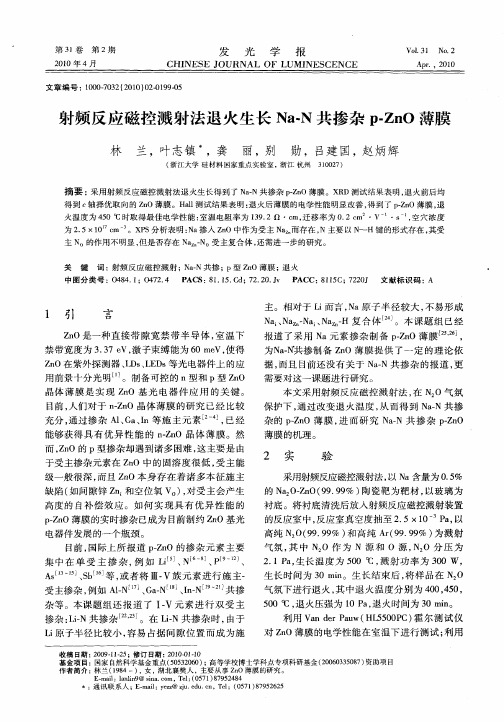
射频 反应磁控溅射法 退火生长 N - aN共 掺 杂 PZ O 薄 膜 -n
林 兰 ,叶 志镇 ,龚 丽 , 别 勋 ,吕建 国 , 炳 辉 赵
( 江大学 硅材料 国家重点实验室 ,浙江 杭州 浙 302 ) 10 7
摘要 : 采用射频反应磁控溅射法退火生长得到了N . a N共掺杂pZO薄膜。X D测试结果表明, -n R 退火前后均
本 文采 用射 频 反应 磁控 溅 射 法 , N O气 氛 在 :
保 护下 , 过改 变 退 火温 度 , 而 得 到 N — 通 从 aN共 掺 杂 的 pZ O 薄 膜 , 而 研 究 N — -n 进 aN共 掺 杂 pZ O -n
薄膜 的机 理 。
充分 , 过掺 杂 A 、 a I 施 主 元 素 叫j已 经 通 lc 、n等 , 能够 获 得 具 有 优 异 性 能 的 nZ O 晶体 薄 膜 。然 —n
目前 , 国际上 所 报 道 pZ O的 掺 杂 元 素 主 要 -n 集 中 在 单 受 主 掺 杂 , 如 L ] N68、 l 、 例 i 、 I-j P9
As l一 l3
、
sl b】 , 者将 Ⅲ. 等 或 V族 元 素 进 行 施 主一 共 掺
生 长 时 间 为 3 n 0mi。生长 结 束后 , 将样 品在 N O : 气 氛下 进行 退 火 , 中退 火 温 度分 别 为 4 0 40 其 0 ,5 , 50q 退 火压 强 为 l a退 火时 间为 3 i。 0 C, 0P , 0rn a 利 用 V ndrPu H 5 0 P 霍 尔测 试 仪 a e aw( L 50 C)
需 要对 这 一课题 进 行研 究 。
Z O是 一种 直 接 带 隙 宽 禁 带 半 导 体 , 温 下 n 室 禁带 宽 度为 33 V, 子束 缚 能为 6 e 使 得 .7e 激 0m V,
- 1、下载文档前请自行甄别文档内容的完整性,平台不提供额外的编辑、内容补充、找答案等附加服务。
- 2、"仅部分预览"的文档,不可在线预览部分如存在完整性等问题,可反馈申请退款(可完整预览的文档不适用该条件!)。
- 3、如文档侵犯您的权益,请联系客服反馈,我们会尽快为您处理(人工客服工作时间:9:00-18:30)。
ZnO薄膜的p型掺杂
[摘要] 氧化锌是一种ⅱ-ⅵ族直接带隙宽禁带化合物半导体材
料。氧化锌为本征n型半导体,存在诸多本征施主缺陷(如氧空位vo
和间隙zni等),对受主掺杂产生高度自补偿作用,加之受主杂质有
限的固溶度或较深的受主能级,使得zno薄膜的p型掺杂非常困难。
目前,关于zno薄膜的p型掺杂理论上已有所研究,但尚未形成共
识;实验上,已有zno薄膜的p型掺杂成功地报道,但重复性不好。
本文旨在在对zno薄膜的p型掺杂的理论和实践进行梳理和总结。
[关键词] zno 薄膜 p型掺杂
1. zno薄膜的结构、性质、应用与缺陷
优质的氧化锌薄膜具有c轴择优取向、纤锌矿结构。晶格常数
a=0.325 nm,c=0.521 nm,为宽带隙半导体,禁带宽度约3.3 ev,
电阻率高于106 ω·cm。
掺铝氧化锌薄膜具有导电性好,透光率高,对紫外线吸收强,红
外反射率高及对微波衰减率高等优点,是一种性能优异的透明导电
薄膜,可用于平面显示器、太阳能电池、透明电板,以及需要阻挡
紫外线、屏蔽热辐射和电磁波的地方。
zno和蓝光材料gan同为六角纤锌矿结构,有相近的晶格常数和
禁带宽度,同时,它的激子激活能高达60 mev,理论上有可能实现
室温下的紫外受激辐射。这一性质使zno薄膜有可能实现紫外激光
发射器件。
氧化锌薄膜中存在一些缺陷,主要包括点缺陷、位错、晶粒间界
等。点缺陷主要有锌空位vzn、氧空位vo、锌间隙原子zni、氧间
隙原子oi、氧反替位锌ozn、锌反替位氧zno等。
氧空位和锌空位分别形成施主和受主能级,氧空位带2个正电荷,
可形成一个浅施主能级和一个深施主能级,浅施主能级在导带以下
约0.03 ev处,深施主能级不确定。锌空位带2个负电荷,可形成
一个浅受主能级和一个深受主能级。
一般情况下生长的单晶zno中被发现锌过剩同时氧欠缺。
2.zno薄膜p型掺杂的困难与掺杂原理
在制备zno材料过程中通常会产生氧空位vo和间隙锌zni,这些
本征缺陷使zno呈n型导电性,所以n型掺杂较容易实现且载流子
浓度容易控制。然而zno的p型掺杂却十分困难,这主要是因为受
主的固溶度较低,并且zno中的诸多本征施主缺陷会产生高度的自
补偿效应。而且zno受主能级一般很深,空穴不容易热激发进入导
带,受主掺杂的固溶度也很低,因此难以实现p型转变。
t.yamamoto对zno电子能带结构的理论计算表明[1]:n型掺杂
(al、ga、in)可以降低晶体madelung能量,而p型掺杂(n、p、as)
却会使之升高。活性施主(al、ga、in)与活性受主(n、p、as)实施
共掺杂,能以施主-受主间的引力取代原有受主间的斥力;增加n、p、
as原子的掺杂浓度,亦可得到更浅的受主能级。al、ga、in同属ⅲ
a族元素,理论计算表明,施主杂质的极化能in3.p型zn0的主要掺
杂方法
3.1 ⅰ族元素掺杂
对于ⅰ族元素掺杂,如: li和na,当它们处于zn位的时候,形成
浅能级受主,由于其较小的离子半径,也容易处于间隙位,形成施主
缺陷而自偿受主。实验显示li掺杂形成了深能级受主,并且在li
位附近容易出现氧空位。euncheol lee等[2]采用基于密度泛函数
理论的第一性原理计算显示na掺杂与li掺杂较为相似。因此,ⅰ
族元素作为受主掺杂很难获得理想结果,不过近来也有用li作为受
主元素采用共掺杂法获得了性能较好的p型zno薄膜。共掺杂法是
日本的yamaoto等[3]提出的。通过对zno电子能带结构的理论计
算表明, n型掺杂(al、ga、in等)可以降低马德隆(madelung)能量,
而p型掺杂(n、p、as等)却会使之升高;用活性施主和活性受主进
行共掺杂可以增加受主元素的掺杂浓度,同时得到更浅的受主能
级。
3.2 ⅴ族元素掺杂
目前,关于zno薄膜p型掺杂的研究主要集中在n、p、as等ⅴ族
元素及其共掺杂上,而n相对于p和as有着更浅的受主能级, n的
离子半径(0.146 nm)和o的离子半径(0.138 nm)较为接近,使得n
更容易替代o的位置形成受主态,因此n被认为是最理想的p型zno
薄膜掺杂元素。
3.2.1n掺杂
n掺杂形成的p型zno薄膜在国内外已有大量的研究报道,其涉及
的掺杂源有n2、n2o、no2、no、nh3等。但由于n_n键能较高(9.9
ev),掺杂时使用仅包含1个n原子的基团(no、no2、n、nh3等)更
容易形成受主态,而对于多个n原子基团的掺杂源则需进行活化处
理后才能作为有效受主,因此,掺杂源对p型转变有着重大影响。
3.2.2p和as掺杂
p和as的离子半径比o的离子半径大很多,zno中掺杂p或as占
据晶格中的o位而成为受主的溶解度不可能太大,因此,在用p或as
掺杂获得的p型zno中, po或aso受主态的贡献可能不是主要的。
limpijumnong等[4]基于第一性原理的计算提出了大失配杂质掺杂
理论,他们认为,大失配的v族掺杂元素(p、as等)不似以前的理论
那样认为其容易占据o的位置,而是更容易占据zn的位置,形成具
有较低形成能和较浅受主能级(0.15 ev)的aszn_2vzn受主复合体。
woo_jin lee等同样用第一性原理对p掺杂zno的缺陷特性进行计
算表明,类似的pzn_2vzn复合体也有着较低的形成能和较浅的受主
能级(0.18 ev)。
较低的受主掺杂浓度以及较深的受主能级都是制约zno薄膜获得
理想p型导电性的因素之一,而共掺杂技术却可以较为有效地提高
受主掺杂浓度,形成更浅的受主能级。目前已有大量的关于用活性
施主(如al、ga、in等)与活性受主(如n、p等)进行共掺杂获得p
型zno薄膜的研究报道。mjoseph等用pld技术通过ga、n共掺杂
成功制备出性能较优异的p型zno薄膜,实验以掺ga2o3的zno作
为靶材,以n2o作为n源并经电子回旋共振活化,以玻璃
(corning#7059)作为衬底时,薄膜的电阻率为0.5 ω·cm,霍尔迁移
率为0.07cm2/vs,载流子浓度为5.5×1019 /cm3;而以蓝宝石(1120)
作为衬底时,则分别是5.8×10⁻³ω·cm, 0.96 cm2/vs和1.1×1021
/cm3。对样品的xps测试表明, ga和n的含量比接近1∶2,由此可
推测出,在zno薄膜中, ga和n形成了n_ga_n的结构,相互之间的
排斥作用减弱,使n的掺杂浓度得以大幅度提高。
4.结语
zno薄膜作为一种新的半导体功能材料,具有廉价、低阻、稳定性
好、光电性能优越等特点, zno薄膜p型掺杂的研究突破必将带来
巨大的产业机遇,推动zno薄膜在光电子领域的大规模应用。目前,
制备p型zno薄膜的方法主要是采用ⅴ族元素掺杂或者ⅲ-ⅴ族元
素共掺杂,掺杂的目的是要可能降低本征材料中的施主缺陷密度,
减弱自补偿效应。有效的掺杂途径主要包括:①活化受主,提高掺杂
效率;②在富zn或共掺杂方式下为n提供一个合适的掺杂环境。另
外,p型薄膜的稳定性受实验条件及衬底温度的影响较大,因而对薄
膜生长过程进行细致的分析非常必要。相信在不久的将来zno的p
型掺杂研究将会取得巨大的进展。
参考文献:
[1]yamamoto t,yoshiba h k.physics and control of
valencestates in zno by codoping method [j]. physica
b,2001,302-303: 155.
[2]eun_cheol leea,chang k j. p_type doping withgroup_i
elements and hydrogenation effect in zno[j].physica
b,2006,376/377:707-710.
[3]yamamoto t, yoshida h k. solution using a codopingmethod
to unipolarity for the fabrication of p_type
zno[j].appl.phys.,1999,38(2b):l166-l169.
[4] limpijumnong s,zhang s b,wei s h,et al. doping
bylarge_size_mismatched impurities: the microscopic
originof arsenic_or antimony_doped p_type zinc
oxide[j].phys.rev.lett.,2004,92: 155-504.