Depth estimation from stereoscopic image pairs assuming piecewise continuous surfaces
stereorectify原理

stere orectif y原理1.引言在计算机视觉领域中,立体视觉是一个重要的研究方向。
通过利用多个摄像头或相机来获取不同视角的图像,我们可以实现诸如深度感知、三维重建和目标检测等应用。
而立体矫正(s t er eo re ct if ic ati o n)是立体视觉中的一个关键步骤,用于对立体图像进行预处理,以便后续的像素匹配和深度计算更加准确。
2.立体视觉基础在了解立体矫正原理之前,我们需要了解一些立体视觉的基础知识。
2.1本质矩阵本质矩阵(e ss en tia l ma tr ix)是描述两个相机之间几何关系的矩阵。
它可以通过摄像头标定得到,是一个3x3的矩阵。
本质矩阵中保存了两个视角之间的相对位置和姿态信息。
2.2极线约束极线约束(e pi po lar c on st ra in t)是立体视觉中一个重要的性质。
假设在一个图像中找到了一个特征点,那么它在另一个图像上的对应点必定在相应的极线上。
这是由于在立体几何中,两个相机的投影光线都通过空间中的一个特定点,从而形成了极线。
3.s t e r e o r e c t i fy原理s t er eo re ct if y的目的是将不同视角下的立体图像进行矫正,使得它们在同一平面上,并且满足极线约束。
这样可以简化后续的图像处理过程。
s t er eo re ct if y原理如下:3.1计算本质矩阵首先,我们需要通过摄像头的标定参数计算出本质矩阵。
摄像头标定是确定相机内参和畸变参数的过程,通过已知的标定板图像来进行。
利用标定参数,我们可以得到两个视角之间的本质矩阵。
3.2计算r e c t i f i c a t i o n变换接下来,我们需要计算用于矫正图像的re c ti fi ca ti on变换。
r e ct if ic at io n变换是一种刚性变换,它将两个视角的相机坐标系变换到同一平面上,并且使得两个相机光轴平行。
3.3应用r e c t i f i c a t i o n变换将r ec ti fi ca ti on变换应用到图像上,即可实现立体图像的矫正。
p3p位姿估计算法

p3p位姿估计算法【最新版】目录1.引言2.P3P 算法的原理3.P3P 算法的优缺点4.P3P 算法的应用5.结论正文【引言】在计算机视觉领域,位姿估计算法是研究物体在三维空间中的位置和姿态的重要方法。
其中,P3P 算法作为一种经典的位姿估计算法,广泛应用于机器人导航、图像处理以及无人驾驶等领域。
本文将对 P3P 算法的原理、优缺点和应用进行详细阐述。
【P3P 算法的原理】P3P(Perspective-n-Point)算法是一种基于透视投影的几何算法,主要用于估计物体的位姿(位置和姿态)。
该算法的基本思想是:通过在物体表面上选取一组特征点,然后在图像中寻找这些特征点的对应点,最后利用这些对应点之间的对极约束关系求解物体的位姿。
具体来说,P3P 算法分为以下几个步骤:1.在物体表面上选取一组特征点,形成一个特征点集。
2.在图像中检测这些特征点,并找到它们在图像中的对应点。
3.计算图像中对应点之间的对极约束关系,形成一个线性方程组。
4.求解线性方程组,得到物体的位姿。
【P3P 算法的优缺点】P3P 算法具有以下优点:1.计算简单:算法的主要计算是线性方程组的求解,计算量相对较小。
2.精度较高:算法基于透视投影原理,理论上可以得到较高的位姿估计精度。
3.适应性强:算法适用于不同形状和纹理的物体,具有较好的通用性。
然而,P3P 算法也存在以下缺点:1.对特征点的选取敏感:特征点的选取对位姿估计结果有一定影响,需要适当选择特征点以提高估计精度。
2.容易受到光照和噪声影响:当图像中存在光照变化和噪声时,算法的性能可能会受到影响。
【P3P 算法的应用】P3P 算法在实际应用中具有广泛的应用前景,主要包括以下几个方面:1.机器人导航:P3P 算法可以用于机器人的位姿估计,从而实现自主导航。
2.图像处理:P3P 算法可以用于三维重建,将二维图像转换为三维模型。
3.无人驾驶:P3P 算法可以用于无人驾驶车辆的位姿估计,从而提高行驶安全性和稳定性。
图像的拼接----RANSAC算法
图像的拼接----RANSAC算法⼀、全景拼接的原理1.RANSAC算法介绍RANSAC算法的基本假设是样本中包含正确数据(inliers,可以被模型描述的数据),也包含异常数据(outliers,偏离正常范围很远、⽆法适应数学模型的数据),即数据集中含有噪声。
这些异常数据可能是由于错误的测量、错误的假设、错误的计算等产⽣的。
同时RANSAC也假设,给定⼀组正确的数据,存在可以计算出符合这些数据的模型参数的⽅法。
2.使⽤RANSAC算法来求解单应性矩阵在进⾏图像拼接时,我们⾸先要解决的是找到图像之间的匹配的对应点。
通常我们采⽤SIFT算法来实现特征点的⾃动匹配,SIFT算法的具体内容参照我的上⼀篇博客。
SIFT是具有很强稳健性的描述⼦,⽐起图像块相关的Harris⾓点,它能产⽣更少的错误的匹配,但仍然还是存在错误的对应点。
所以需要⽤RANSAC算法,对SIFT算法产⽣的128维特征描述符进⾏剔除误匹配点。
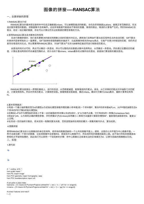
由直线的知识点可知,两点可以确定⼀条直线,所以可以随机的在数据点集中选择两点,从⽽确定⼀条直线。
然后通过设置给定的阈值,计算在直线两旁的符合阈值范围的点,统计点的个数inliers。
inliers最多的点集所在的直线,就是我们要选取的最佳直线。
RANSAC算法就是在⼀原理的基础上,进⾏的改进,从⽽根据阈值,剔除错误的匹配点。
⾸先,从已求得的匹配点对中抽取⼏对匹配点,计算变换矩阵。
然后对所有匹配点,计算映射误差。
接着根据误差阈值,确定inliers。
最后针对最⼤inliers集合,重新计算单应矩阵H。
3.基本思想描述:①考虑⼀个最⼩抽样集的势为n的模型(n为初始化模型参数所需的最⼩样本数)和⼀个样本集P,集合P的样本数#(P)>n,从P中随机抽取包含n 个样本的P的⼦集S初始化模型M;②余集SC=P\S中与模型M的误差⼩于某⼀设定阈值t的样本集以及S构成S*。
S*认为是内点集,它们构成S的⼀致集(Consensus Set);③若#(S*)≥N,认为得到正确的模型参数,并利⽤集S*(内点inliers)采⽤最⼩⼆乘等⽅法重新计算新的模型M*;重新随机抽取新的S,重复以上过程。
光度立体代码

光度立体代码以下是一段简单的光度立体法(Photometric Stereo)代码,实现了从一个图像集合中估计物体的形状。
这个代码只考虑了光线从上方投射下来的情况。
请注意,这个代码是非常基本的,只为了展示基本的思路。
在真实应用中,还需要进行许多优化和改进。
Pythonimport numpy as npfrom scipy import ndimagefrom skimage import iodef photometric_stereo(images, elevations):# 获取图像大小width, height = images[0].shape# 初始化一个全零的输出图像output = np.zeros((width, height))# 对于每一个像素点,遍历所有图像并更新输出图像for x in range(width):for y in range(height):for image_index, elevation in enumerate(elevations):# 计算光线方向light_direction = np.array([0, 0, -1]) + elevation * np.array([0, 0, 1]) / 90# 计算像素点的投影位置projected_x = x - light_direction[0] / light_direction[2] * light_direction[1]projected_y = y - light_direction[1] / light_direction[2] * light_direction[0]# 如果投影点在图像范围内,更新输出图像if 0 <= projected_x < width and 0 <= projected_y < height:output[x, y] += images[image_index][int(projected_x), int(projected_y)]# 归一化输出图像output /= len(images)return output在这个代码中,images是一个包含所有图像的列表,每个图像都是一个灰度图像。
基于深度学习和PnP模型的激光跟踪仪自动姿态测量
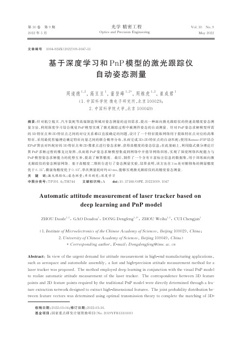
第30卷第9期2022年5月Vol.30No.9May2022光学精密工程Optics and Precision Engineering基于深度学习和PnP模型的激光跟踪仪自动姿态测量周道德1,2,高豆豆1,董登峰1,2*,周维虎1,2,崔成君1(1.中国科学院微电子研究所,北京100029;2.中国科学院大学,北京100049)摘要:针对航空航天、汽车装配等高端制造领域对姿态测量的迫切需求,提出一种面向激光跟踪仪的快速高精度姿态测量方法,利用深度学习结合视觉PnP模型实现了激光跟踪过程中被测件姿态的自动测量。
针对PnP姿态求解模型所需的3D特征点和2D特征点之间的对应关系难以直接确定的问题,设计了一个特征提取网络用于提取特征点对应的高维特征,采用最优传输理论确定特征向量之间的联合概率分布,从而完成3D-2D特征点的自动匹配;使用Ransac-P3P结合EPnP算法对匹配好的3D特征点和2D像素点进行姿态求解,获得高精度的姿态信息;在此基础上,利用隐式微分理论计算PnP求解过程的雅克比矩阵,从而将PnP姿态求解模型集成到网络中并指导网络训练,实现了深度网络匹配能力与PnP模型姿态求解能力的优势互补,提高了解算精度。
最后,制作了一个含有丰富标注信息的数据集,用于训练面向激光跟踪仪的姿态测量网络。
基于高精度二维转台进行了姿态测量实验,结果表明,该方法在3m处对俯仰角的测量精度优于0.31°,横滚角精度优于0.03°,单次测量耗时约40ms,能够实现激光跟踪仪的高精度姿态测量。
关键词:激光跟踪仪;姿态测量;单目视觉;深度学习中图分类号:TP391.4;TH744文献标识码:A doi:10.37188/OPE.20223009.1047Automatic attitude measurement of laser tracker based ondeep learning and PnP modelZHOU Daode1,2,GAO Doudou1,DONG Dengfeng1,2*,ZHOU Weihu1,2,CUI Chengjun1(1.Institute of Microelectronics of the Chinese Academy of Sciences,Beijing100029,China;2.University of Chinese Academy of Sciences,Beijing100049,China)*Corresponding author,E-mail:Dongdengfeng@Abstract:In view of the urgent demand for attitude measurement in high-end manufacturing applications,such as aerospace and automobile assembly,a fast and high-precision attitude measurement method for a laser tracker was proposed.The method employed deep learning in conjunction with the visual PnP model to realize automatic attitude measurement of the laser tracker.The correspondence between3D feature points and2D feature points required by the traditional PnP model were directly determined through a fea⁃ture extraction network designed to extract high-dimensional features.The joint probability distribution be⁃tween feature vectors was determined using optimal transmission theory to complete the matching of3D-文章编号1004-924X(2022)09-1047-11收稿日期:2022-03-04;修订日期:2022-03-16.基金项目:国家重点研发计划资助项目(No.2019YFB1310100)第30卷光学精密工程2D feature points.Subsequently,Ransac-P3P combined with EPnP algorithm was used to obtain high-pre⁃cision attitude information;Based on this,the Jacobian matrix of PnP solution process was calculated us⁃ing implicit differential theory,and the PnP attitude solution model was integrated into the network to guide the training of the network.The complementary advantages of strong depth network matching abili⁃ty and high attitude solution accuracy of the PnP model improved the solution accuracy of the network.In addition,a dataset with rich annotation information was used to train the attitude measurement network for the laser tracker.Finally,an attitude measurement test was conducted using a high-precision two-dimen⁃sional turntable.The experimental results show that the calculation error of pitch angle is less than0.31°,the rolling angle error is less than0.03°,and the single measurement takes approximately40ms.The pro⁃posed method can potentially be applied to attitude measurement scene of the laser tracker.Key words:laser tracker;attitude measurement;monocular vision;deep learning1引言随着制造业的快速发展,在航空航天、汽车装配等领域,大尺寸高精度姿态测量技术越来越重要。
基于深度摄像头的障碍物检测(realsense+opencv)
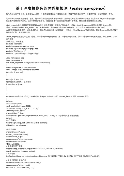
基于深度摄像头的障碍物检测(realsense+opencv)前⼏天⽼⼤给了个任务,让我帮slam组写⼀个基于深度摄像头的障碍物检测,捣⿎了两天弄出来了,效果还不错,就在这⾥记⼀下了。
代码的核⼼思路是⾸先通过⼆值化,将⼀⽶之外的安全距离置零不考虑,然后通过开运算去除掉⼀些噪点(这个后来发现不⼀定有必要),在求出所有障碍物的凸包,这个时候要计算⾯积,当⾯积⼩于⼀定的阈值的时候不予考虑,最终输出障碍物的凸包坐标。
//find_obstacle函数是获取深度图障碍物的函数,返回值是每个障碍物凸包的坐标,参数⼀depth是realsense返回的深度图(ushort型),//参数⼆thresh和参数三max_thresh,是⼆值化的参数,参数四是凸包的最⼩有效⾯积,⼩于这个⾯积的障碍物可以视为噪点。
//函数⾸先筛选掉距离⼤于安全距离的点,然后进⾏阀值化和开运算减少⼀下噪点,⽤findContours得到轮廓图,最后⽤convexHull得到每个障碍物的凸包,最后返回坐标//mask_depth函数是对深度图⼆值化,第⼀个参数image是原图,第⼆个参数th是⽬标图,第三个参数throld是最⼤距离,单位是mm,⼤于这个距离//即为安全,不⽤考虑。
#include <iostream>#include <opencv2/core/core.hpp>#include <opencv2/highgui/highgui.hpp>#include "RSWrapper.h"#include "opencv2/imgproc/imgproc.hpp"using namespace std;using namespace cv;void mask_depth(Mat &image,Mat& th,int throld=1000){int nr = image.rows; // number of rowsint nc = image.cols; // number of columnsfor (int i = 0; i<nr; i++){for (int j = 0; j<nc; j++) {if (image.at<ushort>(i, j)>throld)th.at<ushort>(i, j) = 0;}}}vector<vector<Point> > find_obstacle(Mat &depth, int thresh = 20, int max_thresh = 255, int area = 500){Mat dep;depth.copyTo(dep);mask_depth(depth, dep, 1000);dep.convertTo(dep, CV_8UC1, 1.0 / 16);//imshow("color", color);imshow("depth", dep);Mat element = getStructuringElement(MORPH_RECT, Size(15, 15));//核的⼤⼩可适当调整Mat out;//进⾏开操作morphologyEx(dep, out, MORPH_OPEN, element);//dilate(dhc, out, element);//显⽰效果图imshow("opencv", out);Mat src_copy = dep.clone();Mat threshold_output;vector<vector<Point> > contours;vector<Vec4i> hierarchy;RNG rng(12345);/// 对图像进⾏⼆值化threshold(dep, threshold_output, thresh, 255, CV_THRESH_BINARY);//mask_depth(src, threshold_output);/// 寻找轮廓findContours(threshold_output, contours, hierarchy, CV_RETR_TREE, CV_CHAIN_APPROX_SIMPLE, Point(0, 0));/// 对每个轮廓计算其凸包vector<vector<Point> >hull(contours.size());vector<vector<Point> > result;for (int i = 0; i < contours.size(); i++){convexHull(Mat(contours[i]), hull[i], false);}/// 绘出轮廓及其凸包Mat drawing = Mat::zeros(threshold_output.size(), CV_8UC3);for (int i = 0; i< contours.size(); i++){if (contourArea(contours[i]) < area)//⾯积⼩于area的凸包,可忽略continue;result.push_back(hull[i]);Scalar color = Scalar(rng.uniform(0, 255), rng.uniform(0, 255), rng.uniform(0, 255)); drawContours(drawing, contours, i, color, 1, 8, vector<Vec4i>(), 0, Point()); drawContours(drawing, hull, i, color, 1, 8, vector<Vec4i>(), 0, Point());}imshow("contours", drawing);return result;}int main(int argc, char* argv[]){Mat dhc;Mat dep;int idxImageRes = 1, idxFrameRate = 30;RSWrapper depthCam(idxImageRes, idxImageRes, idxFrameRate, idxFrameRate); if (!depthCam.init()){std::cerr << "Init. RealSense Failure!" << std::endl;return -1;}while (true){//Get RGB-D Imagescv::Mat color, depth;bool ret = depthCam.capture(color, depth);if (!ret) {std::cerr << "Get realsense camera data failure!" << std::endl;break;}vector<vector<Point> > result;result = find_obstacle(depth, 20, 255, 500);if (cvWaitKey(1) == 27)break;}depthCam.release();}。
一种自动标定的方法有两种
一种自动标定的方法有两种自动标定(Automatic calibration)是计算机视觉领域中的重要技术之一,它用于将图像或视频中的物体准确地映射到现实世界的坐标系中。
自动标定技术可以提高计算机视觉系统的准确性和稳定性,广泛应用于机器人导航、虚拟现实和增强现实等领域。
目前,有两种常用的自动标定方法,分别是基于特征点匹配的方法和基于平面标定板的方法。
首先,基于特征点匹配的自动标定方法通过识别和匹配物体上的特征点来确定物体在图像中的位置和姿态。
这种方法首先通过图像处理技术提取物体上的特征点,如角点、边缘等,然后利用特征点之间的几何关系进行匹配。
最常用的特征点匹配算法是SIFT(尺度不变特征变换)和SURF(加速稳健特征),它们能够在图像中提取出具有旋转、尺度和光照不变性的特征点。
通过计算特征点的位置和姿态,可以得到物体在图像中的坐标系和姿态,在此基础上实现自动标定。
然而,基于特征点匹配的自动标定方法存在一些缺点。
首先,特征点提取和匹配的过程比较复杂,需要消耗大量的计算资源和时间。
其次,对于一些没有明显特征点的物体,特征点匹配方法的效果可能不理想。
因此,为了解决这些问题,研究者们提出了基于平面标定板的自动标定方法。
基于平面标定板的自动标定方法利用了平面标定板上的已知几何结构来实现自动标定。
这种方法首先将平面标定板放置在摄像机的视野中,然后利用图像处理技术提取平面标定板上的特征,如角点、边缘等。
接下来,通过计算标定板上特征点之间的几何关系,可以得到摄像机在现实世界的坐标系中的位置和姿态,从而实现自动标定。
相比于基于特征点匹配的方法,基于平面标定板的方法具有计算简单、效果稳定等优点。
然而,基于平面标定板的自动标定方法也存在一些限制。
首先,平面标定板必须放置在摄像机的视野范围内,如果标定板超出了视野范围,就无法实现自动标定。
其次,平面标定板上的特征提取可能受到光照条件的影响,导致标定结果不准确。
因此,在实际应用中,需要根据具体情况选择适合的自动标定方法。
pnp算法位姿估计
pnp算法位姿估计摘要:本文概述了pnp算法位姿估计的基本原理,算法原理和实现,以及pnp算法应用于计算机视觉中的应用及研究进展。
研究表明,pnp算法在多种生成环境中可实现高效的位姿估计,并在计算机视觉方面也有广泛的应用,如三维重建、人体姿态估计、物体识别等。
关键词:pnp算法;位姿估计;计算机视觉;三维重建;人体姿态估计1.简介1.1 PNP算法位姿估计位姿估计是计算机视觉和机器人自动控制中的一个重要问题,它是由相机坐标与世界坐标之间的变换关系(一般是以欧拉角表示)表征的。
求解位姿估计问题的一种常用算法是pnp算法,它用于从两个空间中的点对中估计这种变换关系。
PNP算法(Perspective-n-Points算法)是一种三维物体位姿估计的方法,它由Lambada等人在1994年首次提出,其主要目的是根据已知3D世界点在图像的投影,估计相机的位姿(即位置与旋转角)。
它包含两部分,即PNP问题和PO-RANSAC算法。
PNP问题是求解相机位姿的最小二乘估计问题,PO-RANSAC算法则是用于解决PNP问题的最常用基于随机抽样一致性(RANSAC)算法。
1.2 PNP算法理论原理及实现PNP算法是一种最小二乘优化算法,它允许从3D空间点和其对应的2D图像点之间求解相机位姿。
算法的步骤如下:(1)用已知的2D图像点投影到3D空间点中,构建观测矩阵。
(2)根据观测矩阵求解最小二乘问题,从而得到相机位姿。
(3)根据求得的位姿计算投影矩阵。
(4)将投影矩阵应用于3D空间点,从而计算出其在图像点中的投影。
(5)估计投影误差,以评估求得的模型优度。
(6)如果误差小于某一阈值值,则接受该模型,否则调整参数,重复步骤2-5,直至估计结果满足要求。
2. PNP算法在计算机视觉中的应用PNP算法能够有效的估算三维空间中的相机位姿,并且有效的解决PNP问题,因此被用于计算机视觉中的各类应用中,如全局、局部三维重建、语音导航、机器人自动导航和轨迹检测、人体姿态估计和物体识别等,它能够有效地解决计算机视觉中多项重要问题,极大地拓展了计算机视觉的应用领域。
c++ stereocalibrate函数
C++中的stereocalibrate函数最近,我在学习C++编程的过程中,遇到了一个很有趣的函数:stereocalibrate。
这个函数是用来进行立体相机标定的,可以用来计算相机的内参和外参,从而实现立体视觉的深度感知和三维重构。
在本文中,我将详细介绍stereocalibrate函数的用法和原理,并共享一些我个人的见解和理解。
1. stereocalibrate函数的基本概念让我们来了解一下stereocalibrate函数的基本概念。
在C++中,stereocalibrate函数是在OpenCV库中提供的一个用于立体相机标定的函数。
通过使用这个函数,我们可以从一对立体相机的图像序列中计算出相机的内参和外参,从而实现了立体视觉的相关功能。
2. stereocalibrate函数的参数和用法在实际使用过程中,stereocalibrate函数需要传入一系列参数,包括图像点的坐标、相机矩阵、畸变系数等。
通过调用这个函数,我们可以得到相机的内参矩阵、畸变系数、旋转矩阵和平移向量等相关参数。
这些参数对于立体视觉的后续处理和应用非常重要。
3. stereocalibrate函数的原理在计算的过程中,stereocalibrate函数实际上是通过最小化重投影误差来优化相机参数的。
具体来说,它会利用图像点的坐标和世界坐标点之间的对应关系,以及相机的内参和外参,来最小化重投影误差,并得到最优的相机参数。
4. 我对stereocalibrate函数的理解在我个人的理解中,stereocalibrate函数是一个非常重要的函数,它为我们提供了一种有效的方式来进行立体相机标定。
通过这个函数,我们可以得到相机的内参和外参,从而实现了立体视觉的深度感知和三维重构。
相比于手动标定的方法,stereocalibrate函数可以更加方便快捷地实现相机参数的计算和优化。
总结:在本文中,我详细介绍了C++中的stereocalibrate函数的基本概念、参数和用法,以及其原理和我的个人理解。
alphapose算法介绍及流程
alphapose算法介绍及流程下载温馨提示:该文档是我店铺精心编制而成,希望大家下载以后,能够帮助大家解决实际的问题。
文档下载后可定制随意修改,请根据实际需要进行相应的调整和使用,谢谢!并且,本店铺为大家提供各种各样类型的实用资料,如教育随笔、日记赏析、句子摘抄、古诗大全、经典美文、话题作文、工作总结、词语解析、文案摘录、其他资料等等,如想了解不同资料格式和写法,敬请关注!Download tips: This document is carefully compiled by theeditor.I hope that after you download them,they can help yousolve practical problems. The document can be customized andmodified after downloading,please adjust and use it according toactual needs, thank you!In addition, our shop provides you with various types ofpractical materials,such as educational essays, diaryappreciation,sentence excerpts,ancient poems,classic articles,topic composition,work summary,word parsing,copy excerpts,other materials and so on,want to know different data formats andwriting methods,please pay attention!AlphaPose:深度学习人体关键点检测的领先算法详解AlphaPose,作为深度学习领域中人体关键点检测的领先算法,已经在计算机视觉和人工智能领域引起了广泛的关注。
- 1、下载文档前请自行甄别文档内容的完整性,平台不提供额外的编辑、内容补充、找答案等附加服务。
- 2、"仅部分预览"的文档,不可在线预览部分如存在完整性等问题,可反馈申请退款(可完整预览的文档不适用该条件!)。
- 3、如文档侵犯您的权益,请联系客服反馈,我们会尽快为您处理(人工客服工作时间:9:00-18:30)。
Depth Estimation from Stereoscopic Image PairsAssuming Piecewise Continuos Surfaces
Lutz FalkenhagenInstitut für Theoretische Nachrichtentechnik und InformationsverarbeitungUniversität Hannover, Appelstr. 9A, 30167 Hannover, GermanyEmail: falkenhagen@tnt.uni–hannover.de
AbstractAn algorithm for estimating reliable and accurate depth maps from stereoscopic imagepairs is presented, which is based on block–matching techniques for disparity estima-tion. By taking neighboring disparity values into account, reliability and accuracy of theestimated disparity values are increased and the corona effect at disparity discontinui-ties is avoided. An interpolation of disparity values within segmented regions of homo-geneous disparity enables the computation of dense depth maps by means of triangula-tion.
1IntroductionDepth estimation is used in applications like 3D–modelling of natural objects [1] [2],3D–remote handling and quality control [3]. Depth information is obtained by a trian-gulation of corresponding image points with known stereoscopic camera parameters.Therefore, the coordinate difference between corresponding image points, called dis-parity, has to be estimated. Applying common block–matching techniques for disparityestimation, the correspondence of image points is evaluated using the cross correlationor mean absolute difference of corresponding image blocks [4]. To increase the reliabil-ity of disparity estimates, large block sizes have to be chosen. On the other hand, largeblock sizes decrease the accuracy of disparity estimation. Hierarchical block–matchingcombines both, accuracy and reliability, but gives rise to corona effects at disparitydiscontinuities [5].
The goal of this contribution is to overcome the contradictory requirements of accu-racy and reliability and to avoid the corona effect. The hierarchical block–matching willbe substituted by a non–hierarchical block–matching technique, which uses smallblock–sizes in order to provide accuracy and to avoid the corona effect. Neighboringdisparity estimates are considered in order to provide reliability. A cost function for adisparity estimator will be developed that combines block–matching with a consider-ation of neighboring disparity estimates.
In low textured areas and in areas which are only visible in one image, disparity cannotbe estimated. These areas, called disparity gaps, have be interpolated in order to obtaindense depth maps. Therefore an interpolator has to be developed that preserves disparitydiscontinuities.
Chapter 2 presents the developed disparity estimation algorithm. The computation ofdense depth maps from disparity is explained in Chapter 3. Depth estimation results arepresented for the image sequence ’aqua’, a stereoscopic image sequence acquired bythe RACE–DISTIMA project [6], and compared to common disparity estimation basedon block–matching in Chapter 4 . Chapter 5 concludes this paper.
2Disparity estimation
2.1Model of the Stereoscopic Camera SystemIn the course of disparity and depth estimation, a pinhole camera model based on thecentral projection of diffuse illuminated and diffuse reflecting spatial points in theimage plane is applied. No lense distortion is considered. Each camera is defined by itsposition C³, its optical axis A³ and its image plane, which is determined by two perpen-dicular vectors H³ and V³. The camera is therefore called CAHV–camera [7]. Theprojection of a spatial point P³S+(PSx,PSy,PSz) into the image plane of a CAHV–cam-era can be computed using equation (1).
P³+ǒPhPvǓĄwithĄPh+(P³S*C³)@H³(P³S*C³)@A³Ą,ĄĄPv+(P³S*C³)@V³(P³S*C³)@A³(1)For DISTIMA image sequences, only the intrinsic and relative extrinsic camera param-eters are known, which is sufficient for depth estimation. The absolute camera parame-ters needed for the CAHV–camera model can therefore be chosen arbitrarily for oneof the cameras. Here, the left camera is arranged in the center of the coordinate systemand the right camera is positioned with respect to the known relative camera parameters(Fig. 1). Due to the emulation of human vision in DISTIMA, both cameras are arrangedhorizontally with a base length b and their optical axes have a small convergence anglef. The focal length of both cameras is identical.
Fig. 1:Model of the stereoscopic camera systemleft cameray
zxright camera
P³L
P³R
left image
focal lengthright imageP³SA
³
LA
³
R
viewinglines
C³RC
³
L
epipolar lineV³L
H³L
V³R