数字万用表说明书
2000 2000 2000 2000 数字式万用表 使用手册说明书

2000数字式万用表目录:1、全注意事项2、特点3、技术规格4、仪器结构5、测量方法5-1电流测量5-1-1直流电流测量5-1-2交流电流测量5-2电压测量5-2-1直流电压测量5-2-2交流电压测量5-3电阻测量5-4频率测量6、其它功能6-1自动关机功能6-2信息何持功能6-3范围保持功能7、电池更换方法内容:1、安全注意事项●这台仪器的设计,达到IEC出版的61010安全要求,此使用手册告诫使用者有关安全注意事项,以确保仪器的安全使用。
因此,请在使用前仔细阅读。
●手册中标有※,表明使用者必须严格按照说明进行操作。
※警告⑴在使用仪器前保证读完并理解手册中注意事项。
⑵要根据手册中的方法进行测量及操作。
※危险⑴切勿测量交/直流电压在600V以上的电路。
⑵切勿在有爆炸性气体环境中使用。
(出现易燃性气体或烟、蒸气、雾或者灰尘情况下)⑶当仪器测试线或你的手湿时切勿进行测量。
⑷测量时,输入切勿超出允许的最大范围。
⑸测量时,切勿打开仪器的电池分隔盖。
※注意⑴如果仪器出现下列情况,请不要再试图去测量,例如:仪器有明显损坏,测试头受损和有裸露的金属部分。
⑵当测试笔和金属部分暴露在外时,切勿转动功能开关。
⑶在维修仪器时,切勿安装替代的配件。
⑷如果仪器表面潮湿,请勿更换电池。
⑸关上仪器前,夹钳传感器要与测试电路数断开,关上仪器后,打开电池盖,取出电池。
※小心⑴测量前确认功能选择钮置于下正确的位置。
⑵在做测量时,使用者应该把测试笔放在测试的地方。
⑶避免将仪器暴露于强光下,潮湿环境,露水环境。
⑷使用完毕后,请把范围选择开关设置到“OFF”位置,当长时间不使用本仪器时,请先取出电池再保存。
2、特点⑵在拥挤的区域和紧密的地方易使用夹钳传感器。
⑶在不用夹钳传感器测量时,先关毕在做当前的测量。
⑷自动关机功能。
⑸容易检查连续性的蜂鸣声。
⑹冻结数据读出功能。
⑺显示屏与完整曲线图的刻度是3400个点数。
⑻便于存储外部的信息。
⑼设计符合IEC61010-1:CATⅢ,300V 污染程度2级,的国际安全标准。
数字万用表使用说明书
manual before starting using the instrument. • Save and keep the manual handy to enable quick
(4 ranges) Terminal Voltage:
# CAUTION is reserved for conditions and actions that can cause injury or instrument damage.
# DANGER • Never make measurement on a circuit in which the
# DANGER is reserved for conditions and actions that are likely to cause serious or fatal injury.
# WARNING is reserved for conditions and actions that can cause serious or fatal injury.
The symbol # indicated on the instrument means that the user must refer to related parts in the manual for safe operation of the instrument. Be sure to carefully read the instructions following each symbol in the manual.
4. SPECIFICATIONS
数字万用表(DT)使用说明书(适合初学者

数字万用表(DT9205)使用说明书(适合初学者一、概述本仪表以大规模集成电路、双积分A/D(模/数)转换器为核心,配以全功能过载保护电路,可用来测量直流和交流电压、电流、电阻、电容、二极管、三极管、温度、频率、电路通断等.相关术语及仪表盘上的名词解释:LCD/液晶显示屏;交流电的有效值用字母rms表示.例如,市电峰值为311V,有效值为220Vrms;模/数转换器是模拟信号与数字信号相互转换的电子元件;按下仪表盘左上的HD键可以保持LCD数据键;仪表盘下方FUSED表示该量程有保险管,UNFUSED表示无保险管;15SEC是指测试时间限于15秒二、特点1. 功能选择具有32个量程.量程与LCD有一定的对应关系:选择一个量程,如果量程是一位数,则LCD上显示一位整数,小数点后显示三位小数;如果是两位数,则LCD上显示两位整数,小数点后显示两位小数;如果是三位数,则LCD上显示三位整数,小数点后显示一位小数;有几个量程,对应的LCD没有小数显示.2. 测试数据显示在LCD中.3. 过量程时,LCD的第一位显示"1",其他位没有显示.4. 最大显示值为1999(液晶显示的后三位可从0变到9,第一位从0到1只有两种状态,这样的显示方式叫做三位半.)5. 全量程过载保护6. 工作温度: 00C-400C储存温度:-100C -- +500C7. 电池不足指示:LCD液晶屏左下方显示三、技术指标精确度:±(%读数+第四位上的字数).注意:括号内的第2部分,为精确度的修正值,应放在该档位的最后一位数字上.精确度保证期为1年例如:一个电子元件在200档位的读数为100.0,该档位精确度标示为±(5%+2),该档位在LCD中有一位小数则这个电子元件的实际数据a,介于不等式100-(5%×100.0+0.2)≤a≤100+(5%×100.0+0.2)即94.8≤a≤105.2环境温度:230C±50C相对湿度: <75%1. 直流电压量程分辨率准确度200mV(毫伏)100μV(微伏)±(0.5%+2)2V(伏)1mV(毫伏)20V10mV200V100mV1000V1V±(0.8%+2)单位换算:1V=1000mV(毫伏),1mV=1000μV(微伏)分辨率:感知微小电压变化的能力(大概在1/2000),并反映在万用表的最后一位读数上.例如,在量限为200mV的档位,被测直流电源,其电压读数为100mV.当电压升高50μV(微伏)时,万用表读数仍为100.0;当电压升高150μV(微伏)时,万用表读数的末位会增加一个字,变为100.1测量电压时,万用表如同一个电阻.测量示意图所有量程的输入阻抗为10MΩ(兆欧). 1MΩ=1000000Ω(欧姆)过载保护:对于200mV量程档,能够承受的最大直流电压为250V;能够承受的最大交流电压为250Vrms.其它量程档位,能够承受的最大直流电压为250V;能够承受的最大交流电压有效值为700Vrms,1000V 的峰值.提示:正弦交流电的有效值是其峰值的0.74倍,例如220V的交流市电,其峰值为311V左右.交流电的有效值是用它的热效应规定的:311V的交流电通过负载产生的热效应=220V的直流电通过同一负载产生的热效应.2. 交流电压量程分辨率准确度200mV(毫伏) 100μV(微伏) ±(1.2%+3)2V 1mV ±(0.8%+3)20V 10mV200V 100mV700V 1V ±(1.2%+3)输入阻抗:同直流电压档频率范围: 40Hz to 400Hz ,市电为50Hz,即每秒钟振动50次过载保护: 同直流电压档显示: 交流电的有效值测量准确度的例题:在700V的档位,测一交流电源,读数为230V.考虑到测量是有误差的,问实际电压值a 应该在怎样的范围内?答:因为,700V档位的准确度指标为±(1.2%+3),这一档位没有小数显示.所以230-(1.2%*230+3)≤a≤230+(1.2%*230+3)因为1.2%*230+3=5.76,而万用表的分辨率不能感知不到1V的电压,所以化简后为225≤a≤2353.直流电流量程分辨率准确度2mA(毫安) 1μA(微安) ±(1.2%+2)20mA 10μA(微安)200mA 100μA±(1.4%+2)20A 10mA ±(2.0%+2)单位换算:1A=1000mA , 1mA=1000μA过载保护:20A量程无保险丝,因此,测量时不能超过15秒;其它量程有最大0.2A/250V保险丝.测量电压降:测量直流电流时,万用表好似一个电阻,因此,会在万用表上产生电压降.如果被测电流的读数达到或接近满量程,则在万用表上产生的电压降为200mV.测量示意图:准确度的例题:估计被测电流有10A,选择20A量程档.准确度为±(2.0%+2).因为这一档位显示两位整数和两位小数,所以,实际电流值a的范围10-(2.0%*10+0.02)≤a≤10+(2.0%*10+0.02)即有9.78≤a≤10.224. 交流电流量程分辨率准确度2mA 1μA±(1.2%+3)20mA 10μA200mA 100μA±(1.8%+3)20A 10mA ±(3.0%+7)单位换算:1A=1000mA , 1mA=1000μA过载保护:20A量程无保险丝,因此,测量时不能超过15秒;其它量程有最大0.2A/250V保险丝.测量电压降:测量交流电流时,万用表好似一个电阻,因此,会在万用表上产生电压降.如果被测电流的读数达到或接近满量程,则在万用表上产生的电压降为200mV.频率范围:所测交流电的频率范围限于40Hz to 400Hz.市电为50Hz显示: 交流电的有效值准确度的例题:测一个交流电流源,读数为100mA,该档位精确度标示为±(1.8%+3),该档位LCD显示有一位小数,则这个交流电流源的实际数据a,介于不等式100-(1.8%×100+0.3)≤a≤100+(1.8%×100+0.3)即97.9≤a≤102.15. 电阻量程分辨率准确度200Ω0.1Ω±(1.0%+2)2kΩ1Ω±(0.8%+2)20kΩ10Ω200kΩ100Ω2MΩ1kΩ20MΩ10kΩ±(1.2%+2)200MΩ100kΩ±(5.0%+10)开路电压:测量电阻时,万用表提供的开路电压为700mV,200MΩ档位提供的开路电压为3V.电阻测量图:准确度的例题:一个电阻用20kΩ量程测得阻值为10kΩ,它的实际电阻值a满足10-(0.8%*10+0.02)≤a≤10+(0.8%*10+0.02)化简后为09.90≤a≤10.106.电容量程分辨率准确度2nF 1pF ±(4.0%+5)20nF 10pF200nF 100pF2μF1nF20μF10nF200μF100nF2000μF1μF单位换算: 1F=1000mF ,1mF=1000μF ,1μF=1000nF ,1nF=1000pF法拉毫法微法纳法皮法常用的是微法和皮法:1F=1000000μF,1μF=1000000pF例如:测一个电容,读数为100μF,该档位精确度标示为±(4.0%+5),该档位LCD显示一位小数,则这个电容的实际容量a,介于不等式100-(4.0%×100+0.5)≤a≤100+(4.0%×100+0.5)即94.5≤a≤104.57. (交流)频率(DT9205表没有频率档)量程分辨率准确度2kHz 1Hz ±(2.0%+5)20kHz 10Hz ±(1.5%+5)过载保护:测频率时,万用表能承受的来自交流电源的最大电压为220Vrms四、使用方法:(1)将ON/OFF开关置于ON位置,检查9V电池,如果电池电压不足,""将显示在显示器上,这时则需更换电池.如果显示器没有显示"",则按以下步骤操作.(2)测试笔插孔旁边的""符号,表示输入电压或电流不应超过指示值,这是为了保护内部线路免受损伤.(3)测试之前.功能开关应置于你所需要的量程.4-1 直流电压测量1.将黑表笔插入COM插孔,红表笔插入V/Ω插孔.2.将功能开关置于直流电压档V- 量程范围,并将测试表笔连接到待测电源(测开路电压)或负载上(测负载电压降),红表笔所接端的极性将同时显示于显示器上.两个连接图如下注意:1.如果不知被测电压范围.将功能开关置于最大量程并逐渐下降.2.如果显示器只显示“1”,表示过量程,功能开关应置于更高量程.3.“ ”表示不要测量高于1000V的电压,显示更高的电压值是可能的,但有损坏内部线路的危险.4.当测量高电压时,要格外注意避免触电.4-2交流电压测量1.将黑表笔插入COM插孔,红表笔插入V/Ω插孔.2.将功能开关置于交流电压档V~ 量程范围,并将测试笔连接到待测电源或负载上.测试连接图同上.测量交流电压时,没有极性显示.注意:1.参看直流电压注意1.2. 4.2.“”表示不要输入高于700Vrms的电压,显示更高的电压值是可能的,但有损坏内部线路的危险.4-3直流电流测量1.将黑表笔插入COM插孔,当测量最大值为200mA的电流时,红表笔插入mA插孔,当测量最大值为20A 的电流时,红表笔插入20A插孔.2.将功能开关置于直流电流档A- 量程,并将测试表笔串联接入到待测负载上,电流值显示的同时,将显示红表笔的极性.注意:1.如果使用前不知道被测电流范围,将功能开关置于最大量程并逐渐下降.2.如果显示器只显示“1”,表示过量程,功能开关应置于更高量程.3.""表示最大输入电流为200mA,过量的电流将烧坏保险丝,应再更换,20A量程无保险丝保护,测量时不能超过15秒.4-4交流电流的测量1.将黑表笔插入COM插孔,当测量最大值为200mA的电流时,红表笔插入mA插孔,当测量最大值为20A 的电流时,红表笔插入20A插孔.2.将功能开关置于交流电流档A~ 量程,并将测试表笔串联接入到待测电路中.连接图示注意:1.参看直流电流DCA测量注意1、2、3.4-5电阻测量1.将黑表笔插入COM插孔,红表笔插入V/Ω插孔.2.将功能开关置于Ω量程,将测试表笔连接到待测电阻上.连接图:注意:1.如果被测电阻值超出所选择量程的最大值,将显示过量程“1”,应选择更高的量程,对于大于1MΩ或更高的电阻,要几秒钟后读数才能稳定,这是正常的.2.当没有连接好时,例如开路情况,仪表显示为“1”.3.当检查被测线路的阻抗时,要保证移开被测线路中的所有电源,所有电容放电.被测线路中,如有电源和储能元件,会影响线路阻抗测试正确性.4.万用表的200MΩ档位,短路时有10个字,测量一个电阻时,应从测量读数中减去这10个字.如测一个电阻时,显示为101.0 ,应从101.0中减去10个字.被测元件的实际阻值为100.0即100MΩ.4-6电容测试连接待测电容之前,注意每次转换量程时,复零需要时间,有漂移读数存在不会影响测试精度.1.将功能开关置於电容量程C(F)2.将电容器插入电容测试座中注意:1.仪器本身已对电容档设置了保护,故在电容测试过程中不用考虑极性及电容充放电等情况.2.测量电容时,将电容插入专用的电容测试座中(不要插入表笔插孔COM、V/Ω).3.测量大电容时稳定读数需要一定的时间.4.电容的单位换算:1μF=106pF lμF=103nF4-7频率测量(DT9205表没有频率档)1.将红表笔插入V/Ω插孔,黑表笔插入COM插孔.2.将功能开关置于Hz档位,并将测试笔连接到频率源上,可直接从显示器上读取频率值.4-8温度测量(DT9205表没有温度档)测量温度时,将热电偶传感器的冷端(自由端)插入温度测试座中,热电偶的工作端(测温端)置於待测物上面或内部,可直接从显示器上读取温度值,读数为摄氏OC,传感器的冷端(自由端)不要插入表笔插孔COM、V/Ω.4-9二极管测试及蜂鸣器的连接性测试1.将黑表笔插入COM插孔,红表笔插入V/Ω插孔(红表笔极性为“+”)将功能开关置于“”档、并将表笔连接到待测二极管,读数为二极管正向压降的近似值.连接图示2.将表笔连接到待测线路的两端如果两端之间电阻值低于约70Ω,内置蜂鸣器发声.4-10晶体管hFE测试1.将功能开关置hFE量程.2.确定晶体管是NPN或PNP型,将基极b、发射极e和集电极c分别插入面板上相应的插孔.3.显示器上将读出hFE的近似值,测试条件:万用表提供的基极电流Ib:10μA,集电极到发射极电压为Vce=2.8V4-11自动电源切断使用说明1.仪表设有自动电源切断电路,当仪表工作时间约30分钟-1小时,电源自动切断,仪表进入睡眠状态,这时仪表约消耗7μA的电流.2.当仪表电源切断后若要重新开起电源请重复按动电源开关两次.五、仪表保养该数字多用表是一台精密电子仪器,不要随意更换线路,并注意以下几点:1.不要接高于1000V直流电压或高于700V交流有效值电压.2.不要在功能开关处于Ω和位置时,将电压源接入.3.在电池没有装好或后盖没有上紧时,请不要使用此表.4.只有在测试表笔移开并切断电源以后,才能更换电池或保险丝.六、附件1.使用说明书一本2.表棒一付3.TP01热电偶传感器一套(带温度档的仪表)七、重要说明:仪表功能以多用表上面板功能为准.。
数字万用表说明书

-1-尊敬的顾客感谢您使用本公司生产的产品。
在初次使用该仪器前,请您详细地阅读使用说明书,将可帮助您正确使用该仪器。
我们的宗旨是不断地改进和完善公司的产品,因此您所使用的仪器可能与使用说明书有少许差别。
若有改动,我们不一定能通知到您,敬请谅解!如有疑问,请与公司售后服务部联络,我们定会满足您的要求。
试线、电源插座时,会产生电火花,小心电击,避免触电危险,注意人身安全!-1-◆慎重保证本公司生产的产品,在发货之日起三个月内,如产品出现缺陷,实行包换。
一年(包括一年)内如产品出现缺陷,实行免费维修。
一年以上如产品出现缺陷,实行有偿终身维修。
◆安全要求请阅读下列安全注意事项,以免人身伤害,并防止本产品或与其相连接的任何其它产品受到损坏。
为了避免可能发生的危险,本产品只可在规定的范围内使用。
只有合格的技术人员才可执行维修。
—防止火灾或人身伤害使用适当的电源线。
只可使用本产品专用、并且符合本产品规格的电源线。
正确地连接和断开。
当测试导线与带电端子连接时,请勿随意连接或断开测试导线。
产品接地。
本产品除通过电源线接地导线接地外,产品外壳的接地柱必须接地。
为了防止电击,接地导体必须与地面相连。
在与本产品输入或输出终端连接前,应确保本产品已正确接地。
注意所有终端的额定值。
为了防止火灾或电击危险,请注意本产品的所有额定值和标记。
在对本产品进行连接之前,请阅读本产品使用说明书,以便进一步了解有关额定值的信息。
请勿在无仪器盖板时操作。
如盖板或面板已卸下,请勿操作本产品。
-2-使用适当的保险丝。
只可使用符合本产品规定类型和额定值的保险丝。
避免接触裸露电路和带电金属。
产品有电时,请勿触摸裸露的接点和部位。
在有可疑的故障时,请勿操作。
如怀疑本产品有损坏,请本公司维修人员进行检查,切勿继续操作。
请勿在潮湿环境下操作。
请勿在易爆环境中操作。
保持产品表面清洁和干燥。
-安全术语警告:警告字句指出可能造成人身伤亡的状况或做法。
小心:小心字句指出可能造成本产品或其它财产损坏的状况或做法。
MT-1233C MT-1233D 3-1 2数字万用表用户手册说明书
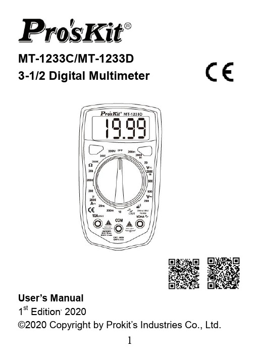
MT-1233C/MT-1233D3-1/2 Digital MultimeterUser’s Manual1st Edition, 2020©2020 Copyright by Prokit’s Industries Co., Ltd.INTRODUCTIONWarningTo avoid electric shock or personal injury, read "Safety Information" and is Warning and Precautions" before using the Mete rSafety information⏹ This series meter Comply with IEC 1010-1 CAT I600V / CAT II 300V overvoltage standards. See specifications⏹ Use the Meter only as specified in this manual,otherwise the protection provided by the Meter may be impaired.⏹ In this manual a Warming identifies conditionsand actions that pose hazards to the user.⏹ A caution identifies conditions and actions thatmay damage the meter ort he equipment under test⏹ International symbols used on the Meter and inthis manual are explained TableTo avoid possible electric shock or personal injury, and to avoid possible damage to the meter or to the equipment under test, comply with the following practices:⏹ Do not use the meter if it is damaged. Before youuse the meter, inspect the case. Pay particularattention to the insulation surrounding theconnectors.⏹ Inspect the test leads for damaged insulation orexposed metal. Check the test leads for continuity.Replace damaged test leads before you use the meter.⏹ Do not use the meter if it operates abnormally.Protection may be impaired. When in doubt, have the meter serviced.⏹ Do not operate the meter around explosive gas,vapor, or dust.⏹ Do not apply more than the rated voltage, asmarked on the meter between terminals orbetween any terminal and earth ground.⏹ Before use, verify the meter's operation bymeasuring a known voltage.⏹ When measuring current, turn off circuit powerbefore connecting the meter in the circuit.⏹ When servicing the meter, use only specifiedreplacement parts. Do not use the Meter in amanner not specified by this manual or the safety features of the meter may be impaired.⏹ Use with caution when working above 30V ac rms,42V ac peak, or 60V dc. Such voltages pose ashock hazard.⏹ When using the probes, keep your fingers behindthe finger guards on the probes.⏹ Connect the common test lead before youconnect the live test lead. When you disconnect test leads, disconnect the live test lead first.⏹ Remove the test leads from the meter before youopen the battery door. Do not operate the meterwith the battery door or portions of the coverremoved or loosened.⏹ To avoid false readings, which could lead topossible⏹ Safety Compliance: IEC 61010-1, 2000 CAT I600V overvoltage standards Do not measurevoltages above 500V in Category installations Overvoltage installations categories per IEC61010-1, 2000: The meter is designed to protect against transients in these categories:CAT I From high-voltage low-energy sources,e.g., electric circuits or a copy machine CAT II From equipment supplied from the fixed installation, e.g., TVs, PCs, portable toolsand household appliancesCAT III From equipment in fixed equipmentinstallations, e.g. installation panels,feeders and short branch circuits, andlighting systems in large buildings. General specifications◆Maximum Voltage between any Terminal andEarth Ground: 1000V◆Measurement rata: updates 2-3/sec.◆Over range indication: "1' figure only in the display ◆Automatic negative polarity indication.◆The is displayed when the battery voltagedrops below the operating voltage◆operating temperature: 0℃~40℃, 0-75% RH.◆Storage temperature: -10℃~50℃, 0-75% RH.◆Power: Single standard 1.5V battery AAAx2◆Dimensions: 130L*72W*28H mm◆Weight approx: 130g (not including battery) FRONT PANEL DESCRIPTION1. LCD Display2. DATA HOLD button3. BACK LIGHT button4. FUNCTION AND RANGE SWITCHThis switch is used to select the function and desired range as well as to turn on the instrument. To extend the life of this battery, the switch should be in the "OFF" position when the instrument is not in use.5. “VΩmA" JACK6. "10A" JACK7. "COM" JACKSPECIFICATIONSAccuracies are guaranteed for 1 year, 23℃±5 ℃, less than 80%RH200mV range and 500V DC or 500V rms for all ranges.of a sine wave.FREQUENCY RANGE: 40Hz ~400Hz OVERLOAD PROTECTION: 500V DC or 500V rms for all ranges.range unused).MEASURING VOLTAGE DROP: 200mV OVERLOAD PROTECTION: 5 second maximum 220V rms.WARNING: DO NOT input any voltage at this range for safety!WARNING: DO NOT input any voltage at this range for safety!OVERLOAD PROTECTION: 5 seconds maximum 220Vrms.WARNING: DO NOT input any voltage at resistance range for safety!302range for safety!OPERATING INSTRUCTIONSWARNING✧ To avoid electrical shock hazard and/or damageof the Instrument, do not measure voltages that might exceed 600V above earth ground.✧ Before the use of instrument, inspect test leads,connectors and probes for cracks, breaks, cracks in the insulation.✧ Dangerous voltages may be present at the inputterminals and may not be displayed.✧ To avoid electrical shock or damage to the meterwhen measuring resistance or continuity in acircuit, make sure the power to the circuit isturned off and all capacitors are discharged.DC & AC VOLTAGE MEASUREMENT1. Connect red test lead to "VΩmA" jack, Black leadto "COM" jack.2. Set RANGE switch to desired VOLTAGE position,if the voltage to be measured is not known before hand, set switch to the highest range and reduce it until satisfactory reading is obtained.3. Connect test leads to device or circuit beingmeasured.4. Turn on power of the device or circuit beingmeasured voltage value will appear on DigitalDisplay along with the voltage polarity.DC CURRENT MEASUREMENT1. Red lead lo "VΩmA". Black lead to "COM”(formeasurements between 200mA and 10A connect red lead to "10A” jack with fully depressed.)2. RANGE switch to desired DCA position.3. Open the circuit to be measured and connectedtest leads INSERIES with the load in with current is to measure.4. Read current value on Digital Display.5. Additionally,"10A"function is designed forintermittent use only. Maximum contact time ofthe test leads with the circuit is 15 seconds with a minimum intermission time of seconds between tests.RESISTANCE MEASUREMENT1. Red lead to "VΩmA". Black lead to "COM".2. RANGE switch to desired OHM position.3. If the resistance being measured is connected toa circuit, turn off power and discharge allcapacitors before measurement.4. Connect test leads LO circuit being measured.5. Read resistance value on Digital Display. DIODE MEASUREMENT1. Red lead to "VΩmA", Black lead to "COM".2. RANGE switch to "' position.3. Connect the red test lead to the anode! of thediode to be measured and black test lead tocathode.4. The forward voltage drop in mV will be displayed.If the diode is reversed, figure "1" will be shown. TEMPERATURE MEASUREMENT(MT-1233C only)1. Connect the K type thermoelectric couple to"VΩmA" and "COM" jacks.2. RANGE switch to TEMP position.3. The display will read Temperature value ℃AUDIBLE CONTINUITY TEST1. Red lead to "VΩmA", Black lead to "COM".2. RANGE switch to “”position.3. Connect test leads to two points of circuit to betested. If the resistance is lower than 30Ω±20Ω, the buzzer will sound.TEST SIGNAL USE (MT-1233D only)1. RANGE switch to "”position.2. A test signal (50Hz) appears between "VΩmA"and "COM” jack, the output voltage is approx 3V p-p with about 50KΩ impedance.MAINTENANCEBeyond replacing batteries and fuses, do not attempt to repair or service your Meter unless you are qualified to do so and have the relevant calibration, performance test and service instruments. The recommended calibration cycle is 12 months.To clean the terminalsa) Push the Meter OFF and remove test leads.b) Shake out any dirt that may be in the terminals.c) Soak a new swab with isopropyl and work around the inside of each input terminald) Use a new swab to apply a light coat of fine machine oil to the inside of each terminal. FUSES TESTWarningTo avoid electric shock or injury, remove the test leads and any input signals before replacing the fuses1. Turn the rotary switch to 200mA position.2. Use a multimeter to measure resistance of"VΩmA" terminal or 10A terminal to COM terminal.✧ A good mA terminal or 10A terminal fuse isindicated by a reading between 0Ω and 10Ω.✧ If the display is overloaded, replace the fuse andtest again.If the display shows any other value, have the meterserviced. See "Service and Parts" later in this manual.BATTERY AND FUSE REPLACEMENT1) Battery and fuse replacement should only bedone after the test leads have been disconnected and power is off.2) Loosen screws with suitable screwdriver andremove case bottom.3) The meter is powered by 1.5V battery (AAAx2).Snap the battery connector leads to the terminals of a new battery and reinsert the battery into the case top. Dress the battery leads so that they will not be pinched between the case bottom andcase top.4) The meter is protected by fast action fuse500mA/250V, dimensions is ¢5*20mm.5) Replace the case bottom and reinstall the threescrews, never operate the meter unless the case bottom is fully dosed.ACCESSORIES⏹User’s manual⏹Set of test leads(CAT I 600V work)⏹K type thermoelectric couple (MT-1233C only) SERVICE AND PARTSIf the Meter fails, check the batteries and fuses first, and then review this manual to make sure that you are operating the Meter correctly一、概述MT-1233C/D儀錶是—種功能齊全,性能穩定,結構新穎,安全可靠的小型掌上型3 1/2位元數位萬用表,可用於測量交直流電壓、直流電流、電阻、二極體正向壓降,有些還可以測量溫度和線路通斷,是廣大用戶隨身攜帶的理想維修工具。
万用表使用说明书

万用表使用说明书万用表使用说明书篇一:数字万用表的使用方法数字万用表的使用与操作摘要:数字万用表是一种多用途的电子测量仪器,在电子线路等实际操作中有着重要的用途。
它不仅可以测量电阻还可以测量电流、电压、电容、二极管、三极管等电子元件和电路。
本文亲自按照步骤动手操作实践并拍下照片与之一一对应,并且,把大家容易出错或不懂得地方尽量详细的解释了。
相信大家看了这篇文章后能很好的使用万用表。
关键词:数字万用表;测量;电子元件;1 引言数字万用表:一种多用途电子测量仪器,一般包含安培计、电压表、欧姆计等功能,有时也称为万用计、多用计、多用电表,或三用电表。
我们用数字万用表测量时需要明白其测量的原理,方法,从而理解性的记忆。
本文介绍了万用表用的最多的几种测量包括:电阻的测量;直流、交流电压的测量;直流、交流电流的测量;二极管的测量;三极管的测量。
2 元件测量2.1 电阻的测量(1)测量步骤首先红表笔插入VΩ孔黑表笔插入COM孔量程旋钮打到“Ω”量程档适当位置分别用红黑表笔接到电阻两端金属部分读出显示屏上显示的数据(2)注意量程的选择和转换。
量程选小了显示屏上会显示“1.” 此时应换用较之大的量程;反之,量程选大了的话,显示屏上会显示一个接近于“0” 的数,此时应换用较之小的量程。
如何读数?显示屏上显示的数字再加上边档位选择的单位就是它的读数。
要提醒的是在“200”档时单位是“?”,在“2k~200k” 图1 测电阻档时单位是“k?”,在“2M~2000M”档时单“M”。
如果被测电阻值超出所选择量程的最大值,将显示过量程“1”,应选择更高的量程,对于大于1MΩ或更高的电阻,要几秒钟后读数才能稳定,这是正常的.当没有连接好时,例如开路情况,仪表显示为“1”当检查被测线路的阻抗时,要保证移开被测线路中的所有电源,所有电容放电.被测线路中,如有电源和储能元件,会影响线路阻抗测试正确性。
万用表的200MΩ档位,短路时有10个字,测量一个电阻时,应从测量读数中减去这10个字。
UT136ABCD 手持式数字万用表 使用说明书
UT136系列使用说明书 UNI-T================================UT136A/B/C/D 手持式数字万用表使用说明书--------------------------------------------一、安全橾作准则UT136系列仪表设计符合GB4793 I及 IEC/EN61010-1、污染2级、过电压标准类别 (CAⅡ600V)和双重绝缘的安全标准。
请遵循本手册的使用说明,否则仪表所提供的保护可能会受到损坏。
1.后盖没有盖好前严禁使用,否则有电击危险:2.使用前应检査表笔绝缘层,应完好,无破损及断线3.液晶显示“”符号时,应及时更换电池,以确保测量精度.4.量程开关应置于正确測里位置。
5.被測信号不允许超过规定的极限值,以防电击和损坏仪表:6.严禁量程开关在测量中改变档位,以防损坏仪表!7.在完成了每次测量操作后.应断开表笔与被测电路的连接:在完成电流测量操作后应先关断电源再断开表笔与被測电路的连接,对大电流的测量更为重要。
8.被脚电压髙于直流60V或交流30Vrms的场合,应小心谨慎,防止触电!9.不要在高溫、高湿环境中使用,尤其不要在潮湿环境中存放,受潮后仪表性能可能变劣。
10.请勿随意改变仪表内部接线,以免损坏仪表和危及安全!11.维护保养请使用湿布和温和的清洁济淌洁仪表外壳,不要使用研磨剂或溶剂!二、电气符号三.综合规范1.输入端子和接地之间的最髙电压:详见各输入端子保护电压说明。
2.10A端子:F10AH250V高分断保险丝φ5x20mm3.mA端子:F0.5AH250V髙分断保险丝φ5x20mm4.最大显示:4000,每秒更新2〜3次。
过量程显示“0L”。
工作温度:0℃〜40℃(32℉〜104℉)相对湿度:0℃〜30℃以下≤75% 30℃〜40℃≤50%储存温度:-10℃〜50℃(14℉〜122℉)5. 电磁兼容性:在1V/m的射频场下:总精度=指定精度+量程的5%,超过1V/m 以上的射频场没有指定指标。
数字万用表设备机操作说明书
在比較困難或危險的量測環境時¸設定到HOLD模式¸眼睛可以只注意測試探針¸等到方便安全時¸再讀顯示器的標示。按[HOLD]鈕¸最後讀值的會被保留在顯示器上。再按一次[HOLD]鈕即可解除
HOLD的功能。
三、注意事項:
1.電源電壓110V/220V均可使用,切勿插錯電源以免燒壞儀器;
1).選擇量測功能
2).按[▲]或[▼]到所需的檔位(假如沒有特定的的輸入值¸建議從最高檔開始)按[AUTO/MAN]鈕選擇手動或自動調整檔位。
3).將測試導線連接到儀器V輸入端和COM輸入端。
4).將測試導線連接到量測點並讀其顯示值。
注意:在量測到1000V的最高電壓後¸測試100μV時可能會發生錯誤。故需先等一分鐘以後再進行低電壓測試。
7.AC+DC量測:
這個功能只使用在電壓或電流量測時。按[AC+DC]鈕¸主顯示器標示出輸入訊號的有校值包括直流成份和交流成份。在這個模式數位電表的讀值率可能會較一般狀況還慢。按其它功能鍵(如Voltage ac or dc, current ac or dc, R,C, Continuity Beeper, Diode Test)即可解除AC+DC的功能。
8.MAX/MIN量測:
在MAX/MIN模式¸數位電表會保留最小和最大讀值。按[MAX/MIN]鈕設定到MAX模式¸會顯示出連續輸入的最大值。按[MAX/MIN]鈕設定到MIN模式¸會顯示出連續輸入的最小值。在MIN模式時¸再按[MAX/MIN]鈕即可解除MAX/MIN的功能。
9.REL量測:
按下[REL]鈕時¸可儲存目前的讀值並顯示接下來量測值與儲存值相差的值。在MAX/MIN模式¸按[REL]鈕設定到REL模式。最大和最小值會成為基準值。
BM99B数字万用表使用说明
BM99智能系列说明书BM99A/99B智能数字多用表使用说明书一、概述感谢使用本公司产品BM99A、BM99B是一种能根据被测量对象自动转换测量功能和量程的智能型数字万用表。
使用2节5号电池供电。
具有完整的过载保护能力。
不同的型号测量功能和智能化程度有所不同,分别可以测量直流电压和电流、交流电压和电流、电阻、电容、频率、二极管、电路通断等。
常规仪表是用机械触点切换测量功能,常因触点生锈而接触不良,影响使用。
本产品采用电子开关切换测量功能,无机械触点,有效避免了各种因触点的故障。
本仪表仅用一个按键便可选择您所要测量的功能。
对于扫描功能,您只需将表笔插入相应的插孔,就可直接测量(可扫描的功能和测量范围请参照技术指标)。
安全规则及注意事项本仪表是按IEC1010600V(CATⅡ)和污染等级2设计的。
使用之前,请仔细阅读本手册。
1. 电气符号直流 ~交流二极管蜂鸣通断电池不足接地警告提示双重绝缘高压危险2. 测量时,电流输入插孔不能输入电压,电压输入插孔不能输入大于600伏的有效值或1000峰值电压。
3. DC50V以上的直流或AC36V以上的交流都可能产生电击危险,测量时均应小心操作。
4. 仪表应避免阳光直射、高温、潮湿。
5. 长期不用应取出电池,以免电池漏液,损坏部件。
注意:本仪表必需用全护套测试表笔,否则无法使用电流测量功能。
不熟悉仪表的用户最好不要测量电流。
二、一般特性1. 显示方式:采用液晶显示器2. 最大显示:1999(BM99A 3 1/2位) 或2999(BM99B 3 2/3位)3. 过量程显示:最高位显示“OL”4. 自动负极性指示:显示“一”5. 电池不足指示:: “ ”6. 工作环境:0℃~40℃,80%RH(最大)7. 储存环境:-20℃~60℃,85%RH(最大)8. 电源:AA1.5V电池2节(LR6×2)9. 保险管:F200mA/250V (BM99A)或F500mA/250V (BM99B) F10A/250V 几何尺寸Φ5*20mm10. 自动关机:开机约10分钟后BM99A将自动关机、BM99B将进入休眠状态;在休眠状态下按SELEC T键能开机,在自动关机状态下,长按SELEC T键约2秒开机。
106 107数字万用表用户手册说明书
June 2013, Rev. 1, 10/15 © 2013-2015 Fluke Corporation. All rights reserved. Specifications are subject to change without notice. All product names are trademarks of their respective companies.106/107 Digital MultimetersTable of ContentsTitle Page Introduction (1)How to Contact Fluke (1)Safety Information (2)Instrument Overview (8)Terminals (8)Display (9)Auto Power Off (10)Auto Backlight Off (11)Measurements (11)Data Hold (11)Measure AC and DC Voltage (12)Measure AC or DC Current (14)Measure Resistance (16)Test for Continuity (16)Test Diodes (107 Only) (18)i106/107 Users ManualiiMeasure Capacitance (19)Measure Frequency and Duty Cycle (107 Only) (19)Maintenance (20)General Maintenance (21)Test the Fuse (22)Replace Batteries and the Fuse (22)Service and Parts (24)General Specifications (25)Accuracy Specifications (28)Digital Multimeters Safety Information3WarningTo prevent possible electrical shock, fire, or personal injury:• Carefully read all instructions.• Read all safety information before you use the Product. • Use the Product only as specified, or the protection supplied by the Product can be compromised.• Do not use the Product around explosive gas, vapor, or in damp or wet environments.• Do not use the Product if it is damaged.• Disable the Product if it is damaged.• Do not use the Product if it operates incorrectly.• Examine the case before you use the Product. Look for cracks or missing plastic. Carefully look at the insulation around the terminals.• Use only correct measurement category (CAT), voltage, and amperage rated probes, test leads, and adapters for the measurement.• Measure a known voltage first to make sure that the Product operates correctly.106/107 Users Manual4 •Do not use test leads if they are damaged. Examine the test leads for damaged insulation and measure a known voltage.•Do not apply more than the rated voltage, between the terminals or between each terminal and earth ground.•Do not use the HOLD function to measure unknown potentials. When HOLD is turned on, the display does not change when a different potential is measured. •Do not touch voltages >30 V ac rms, 42 V ac peak, or 60 V dc.•Keep fingers behind the finger guards on the probes.•Remove all probes, test leads, and accessories before the battery door is opened.•Do not exceed the Measurement Category (CAT) rating of the lowest rated individual component of a Product, probe, or accessory.•Remove the input signals before you clean the Product.•Have an approved technician repair the Product.•Remove the batteries if the Product is not used for an extended period of time, or if stored in temperatures above 50 °C. If the batteries are not removed,battery leakage can damage the Product.Digital Multimeters Safety Information 5• Replace the batteries when the low battery indicator shows to prevent incorrect measurements.• Use only specified replacement parts.• Use only specified replacement fuses.• Limit operation to the specified measurement category, voltage, or amperage ratings.• Do not use test leads if they are damaged. Examine the test leads for damaged insulation and measure a known voltage.• Do not use in CAT III or CAT IV environments without the protective cap installed. The protective cap decreases the exposed probe metal to <4 mm. This decreases the possibility of arc flash from short circuits.106/107 Users Manual6Table 1 is a list of the symbols used on the Product and in this manual. Table 1. SymbolsConsult user documentation. WARNING. RISK OF DANGER. Static awareness. Static discharge can damage part(s). WARNING. HAZARDOUS VOLTAGE.Risk of electric shock.AC (Alternating Current) EarthDC (Direct Current) CapacitanceBoth direct and alternating current DiodeBattery FuseConforms to relevant South KoreanEMC Standards Certified by TÜV SÜD Product Service. Conforms to European Union directives. Certified by CSA Group to North Americansafety standards.Digital Multimeters Safety Information 7 Table 1. Symbols (cont.)Measurement Category II is applicable to test and measuring circuits connected directly to utilization points (socket outlets and similar points) of the low-voltage MAINS installation.Measurement Category III is applicable to test and measuring circuits connected to the distribution part of the building’s low-voltage MAINS installation. Measurement Category IV is applicable to test and measuring circuits connected at thesource of the building’s low-voltage MAINS installation.This product complies with the WEEE Directive marking requirements. The affixed label indicates that you must not discard this electrical/electronic product in domestic household waste. Product Category: With reference to the equipment types in the WEEE Directive Annex I, this product is classed as category 9 "Monitoring and Control Instrumentation" product. Do not dispose of this product as unsorted municipal waste.8Digital Multimeters Instrument Overview9DisplayFigure 1 and Table 2 show the items on the Product display.hhc02.epsFigure 1. Display106/107 Users Manual10 Table 2. DisplayItem Description Item DescriptionHighvoltage Frequency is selected Display Hold is enabled FaradsContinuityselected MillivoltsDiode test is selected Amps or voltsDuty Cycle is selected Dc or ac voltage or currentDecimalprefix Auto Range mode is enabled Ohmsisselected Low battery. Replace battery. Auto Power OffThe Product automatically powers off after 20 minutes of inactivity.To restart the Product, turn the rotary switch back to the OFF position and then to a necessary position.To disable the Auto Power Off function, hold down the YELLOW button when turning on the Product, until PoFF shows on the display.Digital Multimeters Auto Backlight Off11Auto Backlight OffThe backlight automatically turns off after 2 minutes of inactivity.To disable the Auto Backlight Off function, hold down when turning on the Product, until LoFF shows on the display.NoteTo disable both the Auto Power Off function and the Auto Backlight Off function, hold down the YELLOW button and at the same time, until both PoFF and LoFF show on the display.MeasurementsData HoldWarningTo prevent possible electrical shock, fire or personal injury, do not use the HOLD function to measure unknown potentials. When HOLD is turned on, the display does not change when a different potential is measured.To hold the present reading, push . Push again to continue normal operation.106/107Users Manual12Measure AC and DC Voltage To measure ac and dc voltage:1. Choose ac or dc by turning the rotary switch to or .2. Connect the red test lead to the terminal and the black test lead to the COMterminal. 3. Measure the voltage by touching the probes to the correct test points of the circuit. 4. Read the measured voltage on the display.Digital MultimetersMeasurements13Figure 2. Measure AC and DC Voltage106/107Users Manual14Measure AC or DC CurrentWarningTo prevent possible electrical shock, fire, or personal injury, remove circuit power before you connect the Product in the circuit when you measure current. Connect the Product in series with the circuit. 1. Turn the rotary switch to .2. Push the YELLOW button to toggle between ac or dc current measurement.3. Connect the red test lead to the A terminal to be measured and connect the black testlead to the COM terminal. 4. Break the circuit path to be measured.5. Connect the test leads across the break and apply power.6. Read the measured current on the display.Digital MultimetersMeasurements15Figure 3. Measure AC and DC Current106/107Users Manual 16Measure Resistance1. Turn the rotary switch to (106 does not have ). Make sure power is disconnectedfrom the circuit to be measured. 2. Connect the red test lead to the terminal and the black test lead to the COMterminal. 3. Measure the resistance by touching the probes to the desired test points of the circuit. 4. Read the measured resistance on the display. Test for ContinuityWith the resistance mode selected, push the YELLOW button once to activate the continuity mode. If the resistance is <70 Ω, the beeper sounds continuously, designating a short circuit. If the Product reads , the circuit is open.Digital MultimetersMeasurements17Figure 4. Measure Resistance/Continuity106/107Users Manual18Test Diodes (107 Only) 1. Turn the rotary switch to .2. Push the YELLOW button twice to activate the diode test mode.3. Connect the red test lead to the terminal and the black test lead to the COMterminal. 4. Connect the red probe to the anode and the black test lead to the cathode of the diodebeing tested. 5. Read the forward bias voltage value on the display.6. If the polarity of the test leads is reversed with diode polarity, the display reading shows. This can be used to distinguish the anode and cathode sides of a diode.Digital MultimetersMeasurements19Measure Capacitance 1. Turn the rotary switch to .2. Connect the red test lead to the terminal and the black test lead to the COMterminal. 3. Touch the probes to the capacitor leads. 4. Let the reading stabilize (up to 18 seconds). 5. Read the capacitance value on the display. Measure Frequency and Duty Cycle (107 Only)The Product can measure frequency or duty cycle while making either an ac voltage or an ac current measurement.1. Pushto change the Product to frequency or duty cycle. 2. When the Product is in the required function (ac voltage or ac current), push . 3. Read the frequency on the display.4. To make a duty cycle measurement, push again.5. Read the percent of duty cycle on the display.106/107Users Manual20MaintenanceBeyond replacing the batteries and fuse, do not attempt to repair or service the Product unless you are qualified to do so and have the relevant calibration, performance test, and service instructions. The recommended calibration cycle is 12 months.WarningTo prevent possible electrical shock, fire, or personal injury: • Remove the input signals before you clean the Product. • Use only specified replacement parts. • Use only specified replacement fuses.• Have an approved technician repair the Product.For safe operation and maintenance of the Product, repair the Product before use if the batteries leak.Digital MultimetersMaintenance21General MaintenancePeriodically wipe the case with a damp cloth and mild detergent. Do not use abrasives or solvents. Dirt or moisture in the terminals can affect readings. To clean the terminals:1. Turn the Product off and remove the test leads.2. Shake out any dirt that may be in the terminals.3. Soak a new swab with isopropyl alcohol and work around the inside of each inputterminal. 4. Use a new swab to apply a light coat of fine machine oil to the inside of each terminal.106/107Users Manual 22Test the Fuse1. Turn the rotary switch to (106 does not have ).2. Plug a test lead into the terminal and touch the probe to the A terminal.• A good A terminal fuse is indicated by a reading less than 0.1 Ω. • If the display reads , replace the fuse and test again.• If the display shows any other value, have the Product serviced. See Service andParts . Replace Batteries and the FuseTo replace the batteries or the fuse, see Figure 5.CautionBe sure to observe Electro Static Discharge precautions.Digital Multimeters Service and Parts23Figure 5. Replace Batteries and the Fuse106/107Users Manual24Service and PartsIf the Product fails, first check the batteries and fuse. Then, review this manual to make sure you are operating the Product correctly. Replacement parts are:ItemFluke Part NumberBatteries 2838018Battery door 4319659 Test leads TL1754306653Fuse 803293 Screws 4320657Digital Multimeters General Specifications25General SpecificationsMaximum voltage between any terminaland Earth Ground ............................................................ 600 VFuse protection for A input ............................................ 11 A, 1000 V, IR 17 kA Display (LCD)................................................................... 6000 counts, updates 3/sec Battery Type .................................................................... 2 AAA, NEDA 24A, IEC LR03 Battery Life ...................................................................... 200 hours minimum TemperatureOperating ...................................................................... 0 °C to 40 °C Storage ......................................................................... -30 °C to 60 °C Relative HumidityOperating Humidity ....................................................... Non-condensing when <10 °C;≤90 % at 10 °C to 30 °C; ≤75 % at 30 °C to 40 °C Operating Humidity, 40 M Ω Range ............................... ≤80 % at 10 °C to 30 °C;≤70 % at 30 °C to 40 °C AltitudeOperating ...................................................................... 2000 m Storage ......................................................................... 12,000 m106/107Users Manual26Temperature Coefficient ................................................. 0.1 X (specified accuracy) / °C (<18 °C or>28 °C) Size (HxWxL).................................................................... 142 mm x 69 mm x 28 mm Weight .............................................................................. 200 gIP Rating ........................................................................... IEC 60529: IP 40 SafetyGeneral ......................................................................... IEC 61010-1: Pollution Degree 2 Measurement ................................................................ IEC 61010-2-033: CAT III 600 V Electromagnetic Compatibility (EMC)International .................................................................. IEC 61326-1: Portable, IEC 61326-2-2CISPR 11: Group 1, Class A Group 1: Equipment has intentionally generated and/or uses conductively-coupled radio frequency energy that is necessary for the internal function of the equipment itself.Class A: Equipment is suitable for use in all establishments other than domestic and those directly connected to a low-voltage power supply network that supplies buildings used for domestic purposes. There may be potential difficulties in ensuring electromagnetic compatibility in other environments due to conducted and radiated disturbances.Digital Multimeters General Specifications27Emissions that exceed the levels required by CISPR 11 can occur when the equipment is connected to a test object. The equipment may not meet the immunity requirements of this standard when test leads and/or test probes are connected.Korea (KCC) ................................................................. Class A Equipment (Industrial Broadcasting &Communication Equipment) Class A: Equipment meets requirements for industrial electromagnetic wave equipment and the seller or user should take notice of it. This equipment is intended for use in business environments and not to be used in homes.USA (FCC) ................................................................... 47 CFR 15 subpart B. This product is consideredan exempt device per clause 15.103.106/107Users Manual28Accuracy SpecificationsAccuracy is specified for 1 year after calibration, at operating temperatures of 18 °C to 28 °C, relative humidity at 0 % to 75 %. Accuracy specifications take the form of: ±([% of Reading] + [Number of Least Significant Digits]).Function Range Resolution Accuracy 106 107 AC Volts(40 Hz to 500 Hz) [1]6.000 V 60.00 V 600.0 V 0.001 V 0.01 V 0.1 V 1.0 % + 31.0 % + 3DC Volts6.000 V 60.00 V 600.0 V 0.001 V 0.01 V 0.1 V 0.5 % + 3 0.5 % + 3AC Millivolts600.0 mV0.1 mV3.0 % + 3 3.0 % + 3Diode Test [2]2.000 V 0.001 V N/A 10 %[1] All AC, Hz, and duty cycle are specified from 1 % to 100 % of range. Inputs below 1 % of range are not specified. [2] Typically, open circuit test voltage is 2.0 V and short circuit current is <0.6 mA.Digital MultimetersAccuracy Specifications29FunctionRange Resolution Accuracy106 107 Resistance400.0 Ω 4.000 k Ω 40.00 k Ω 400.0 k Ω 4.000 M Ω 40.00 M Ω 0.1 Ω 0.001 k Ω 0.01 k Ω 0.1 k Ω 0.001 M Ω 0.01 M Ω 0.5 % + 3 0.5 % + 2 0.5 % + 2 0.5 % + 2 0.5 % + 2 1.5 % + 3 0.5 % + 3 0.5 % + 2 0.5 % + 2 0.5 % + 2 0.5 % + 2 1.5 % + 3 Capacitance [1]50.00 nF 500.0 nF 5.000 µF 50.00 µF 500.0 µF 1000 µF0.01 nF 0.1 nF 0.001 µF 0.01 µF 0.1 µF 1 µF2 % + 5 2 % + 5 5 % + 5 5 % + 5 5 % + 5 5 % + 52 % + 5 2 % + 5 5 % + 5 5 % + 5 5 % + 5 5 % + 5106/107 Users Manual30Function Range ResolutionAccuracy106 107Frequency [2]Hz(10 Hz to 100 kHz)50.00 Hz500.0 Hz5.000 kHz50.00 kHz100.0 kHz0.01 Hz0.1 Hz0.001 kHz0.01 kHz0.1 kHzNA 0.1 % + 3 Duty Cycle [2] 1 % to 99 % 0.1 % NA 1 % typical [3][1] Specifications do not include errors due to test lead capacitance and capacitance floor (may be up to 1.5nF in the50nF range).[2] All AC, Hz, and duty cycle readings are specified from 1 % to 100 % of range. Inputs below 1 % of range are notspecified.[3] Typical means when the frequency is at 50Hz or 60Hz and the duty cycle is between 10 % and 90 %.Digital MultimetersAccuracy Specifications31Function Range ResolutionAccuracy 106 107 AC Current (40 Hz to 200 Hz)[1]4.000 A 10.00 A 0.001 A 0.01 A 1.5 % + 31.5 % + 3DC Current[1]4.000 A 10.00 A0.001 A 0.01 A1.5 % + 3 1.5 % + 3[1] 10 A duty cycle <7 minutes on, 20 minutes off, 25 °C to 40 °C.106/107 Users Manual32Function OverloadProtectionInput Impedance(Nominal)Common ModeRejection RatioNormal ModeRejection Ratio AC Volts 600 V [1] >10MΩ <100 pF [2]>60 dB at dc,50 Hz or 60 Hz_AC Millivolts 600 mV >1 M, <100 pF>80 dB at dc,50 Hz or 60 Hz_DC Volts 600 V [1] >10MΩ <100 pF>100 dB at50 Hz or 60 Hz>60 dB at50 Hz or 60 Hz[1] 6 x 10⁵ V Hz Max.[2] For mV (AC), input impedance is approximately 1MΩ.。
- 1、下载文档前请自行甄别文档内容的完整性,平台不提供额外的编辑、内容补充、找答案等附加服务。
- 2、"仅部分预览"的文档,不可在线预览部分如存在完整性等问题,可反馈申请退款(可完整预览的文档不适用该条件!)。
- 3、如文档侵犯您的权益,请联系客服反馈,我们会尽快为您处理(人工客服工作时间:9:00-18:30)。
May 2003 Rev. 2, 10/15 (Simplified Chinese)© 2003-2015 Fluke Corporation. All rights reserved. Specifications are subject to change without notice. All product names are trademarks of their respective companies. 175, 177, 179 True-rms Multimeters终生有限保证Fluke 保证每一台Fluke 20、70、80、170 和 180系列的 DMM,其用料和做工都是终生毫无瑕疵的。
此处所谓的“终生”是指Fluke终止制造本产品后七年,但本项保证期应自产品购买日起至少十年内有效。
本项保证不包括保险丝、可弃置的电池以及因疏忽、误用、污染、改变、意外或非正常状况下的使用或处理所造成的损坏(包括使用产品规范以外的测量所引起的故障或机械部件的正常损耗)。
本项保证仅适用于原购买者并且不得转让。
自购买日起十年内,本保证也包括 LCD。
十年以后直到仪表的终生,Fluke 将以收费的方式更换 DMM 的 LCD(根据当时该组件的成本价格收取费用)。
欲建立原购买者与购买日期的根据,请填妥并寄回产品所附上的注册登记卡,或在上注册产品。
对于从Fluke授权销售处以适当的国际价格所购买而损坏的产品,Fluke 可选择免费修理、更换或以原购买价退款的方式处理该产品。
若产品是从一个国家购买却被送到其它地区修理,Fluke 保留收取修理/更换零件的进口费用的权利。
如果发现产品损坏,请和最靠近您的 Fluke 授权服务中心联络以取得同意退回产品的信息,然后请把产品寄到该服务中心。
请说明遭遇到困难的地方,并预付邮资和保险费(目的地离岸价格)。
Fluke 不负责产品在运输上的损坏。
对保修产品的修理或更换,Fluke 将负责回邮的运输费用。
对非保修产品的修理,Fluke 会对修理费用作出估价并取得您的同意以后才进行修理,修理后Fluke将向您收取修理和回邮的运输费用。
本项保证是您仅有的补偿。
除此以外,没有任何其它明示或默示的保证(包括保证某一特殊目的的适应性)。
凡因任何原因或原理而引起的特别、间接、附带或继起的损坏或损失(包括数据的损失),FLUKE 也一概不予负责。
授权的代理商无权代表 Fluke 延长本项保证。
由于某些州不允许对默示保证及附带或继起的损坏有所限制,本保证的限制或许不适用于您。
若本保证的任何条款被法庭或其它具有司法管辖权的决定者裁定为不适用或不可执行时,该项裁定将不得影响其它条款的有效性或执行性。
Fluke Corporation Fluke Europe B.V.P.O. Box 9090 P.O. Box 1186Everett, WA 98206-90905602 BD EindhovenU.S.A.TheNetherlands2/02目录标题页码概述 (1)如何联系 Fluke (1)安全须知 (1)符号 (3)危险电压 (5)测试导线警示 (5)端子 (5)产品按钮 (6)旋转开关档位 (6)显示屏 (7)电池省电装置(睡眠模式) (9)最小最大平均 (MIN MAX AVG) 记录模式 (9)显示保持 (Display HOLD) 和自动保持 (AutoHOLD) 模式 (10)手动量程 (Manual Range) 和自动量程 (Autorange) (10)启动电源选项 (11)基本测量 (11)测量交流电压和直流电压 (12)测量电阻 (12)测量电容 (12)通断性测试 (13)测量温度(仅限 179) (13)测试二极管 (13)测量交流或直流电流 (14)真有效值仪表的交流零输入行为 (14)测量频率 (15)交流/直流电压频率 (15)交流电流频率 (15)使用模拟指针显示 (16)i175, 177, 179用户手册维护 (16)清洁本产品 (17)测试保险丝 (17)更换电池和保险丝 (17)技术指标 (18)电气技术指标 (20)ii概述Fluke 175、177 和 179 均为使用电池工作的真有效值万用表(以下称“产品”),配备 6000-计数、3 ¾ 位显示和模拟指针显示。
此手册适用于所有三种型式。
所有图形均以 179 型为例。
如何联系 Fluke要联系 Fluke,请拨打以下电话号码:•美国技术支持: 1-800-44-FLUKE (1-800-443-5853)•美国校准/修理: 1-888-99-FLUKE (1-888-993-5853)•加拿大: 1-800-36-FLUKE (1-800-363-5853)•欧洲: +31-402-675-200•日本: +81-3-6714-3114•俄罗斯: +8-495-664-75-12•新加坡: +65-6799-5566•世界任何地区: +1-425-446-5500 或者,请访问 Fluke 公司网站:。
如需注册产品,请访问。
要查看、打印或下载最新版的手册补充页,请访问/usen/support/manuals。
安全须知在本手册中,警告表示会对用户造成危险的状况和操作。
小心表示可能对产品或受测设备造成损坏的状况和操作。
XW警告为了防止可能发生的触电、火灾或人身伤害:•在使用产品前,请先阅读所有安全须知。
•仔细阅读所有说明。
•请仅将产品用于指定用途,否则可能减弱产品提供的防护。
1175, 177, 179 用户手册2•使用产品前先检查外壳。
检查是否存在裂纹或塑胶缺损。
请仔细检查端子附近的绝缘体。
•请勿在爆炸性气体和蒸汽周围或潮湿环境中使用本产品。
•不要单独工作。
•应按照指定的测量类别、电压或电流额定值使用。
•遵守当地和国家的安全规范。
穿戴个人防护用品(经认可的橡胶手套、面具和阻燃衣物等),以防危险带电导体裸露时遭受电击和电弧而受伤。
•进行所有测量时,请使用本产品批准的测量类别 (CAT)、电压和额定电流附件(探头、测试导线和适配器)。
•请勿超出产品、探针或附件中额定值最低的单个元件的测量类别 (CAT) 额定值。
•交流电压真有效值高于 30 V、交流电压峰值高于 42 V 或直流电压高于 60 V 时,请勿触摸。
•请将手指握在探针护指装置的后面。
•请仅使用产品随附的电流探针、测试导线和适配器。
•测量时,请先连接零线或地线,再连接火线;断开时,请先切断火线,再断开零线和地线。
•若产品损坏,请将其禁用。
•若产品损坏,请勿使用。
•若产品工作异常,请勿使用。
•只能使用测量类别、电压和电流额定值与本产品相同的探针、测试导线和附件。
•产品长期不使用或存放在高于 50 °C 的环境中时,请取出电池。
如未取出电池,电池漏液可能损坏产品。
True-rms Multimeters符号3• 操作本产品前请确保电池盖关闭且锁定。
• 请仅使用具有正确额定电压的电缆。
• 打开电池盖之前,首先断开所有探针、测试线和附件。
• 当显示电池电量不足指示时请更换电池,以防测量不正确。
• 端子间或每个端子与接地点之间施加的电压不能超过额定值。
• 先测量一个已知电压,以确定产品运行是否正常。
• 测量时,必须使用正确的端子、功能档和量程档。
• 请勿使用已损坏的测试导线。
检查测试导线绝缘层是否破损、是否有裸露金属或有磨损迹象。
检查测试导线的通断性。
• 当测试导线连接到电流端子时,请勿让探针接触电压源。
• 请勿使用已损坏的测试导线。
检查测试导线是否绝缘不良,并测量已知的电压。
• 请勿在测试探头未安装保护帽的情况下在 CAT III 或 CATIV 环境中使用探头。
保护帽能够将探头的裸露金属部分减少至不到 4 mm 。
这样就降低了因短路产生弧闪的可能性。
符号表 1 列出了本产品以及本手册中使用的符号。
表 1. 符号符号说明请参阅用户文档。
W 警告。
危险。
X 警告。
危险电压。
触电危险。
接地AC (交流电) DC (直流电)直流电和交流电175, 177, 179 用户手册4表 1. 符号(续)符号说明接地电容保险丝P符合欧盟指令。
T双层绝缘电池电量不足,请更换电池。
最小保险丝熔断额定值。
R通断性测试或通断性蜂鸣器声调。
P符合欧盟指令。
)经 CSA Group 认证符合北美安全标准。
通过 TÜV SÜD Product Service 认证。
符合相关的澳大利亚安全和 EMC 标准。
Ã符合相关的韩国 EMC 标准。
表 1. 符号(续)符号说明II 类测量适用于测试和测量与低电压电源装置的用电点(插座和相似点)直接连接的电路。
III 类测量适用于与建筑物低压电源装置配电部分连接的测试和测量电路。
IV 类测量适用于测试和测量与建筑物低电压电源装置电源部分连接的电路。
~本产品符合 WEEE 指令的标识要求。
粘贴的标签指示不得将本电气/电子产品作为家庭垃圾丢弃。
产品类别:根据 WEEE 指令附录 I 中的设备类型,该产品被归类为第 9 类“监测和控制仪器”产品。
请勿将本产品作为未分类的城市废弃物处理。
True-rms Multimeters危险电压5危险电压电压测量期间,本产品会警告您可能存在危险电压。
当产品检测到电压 ≥30 V 或检测到过载电压 ( ) 时,显示屏上将出现符号 Y 以提醒您可能存在危险电压。
测试导线警示为了提醒您检查测试导线是否处于正确的端子中,当您将旋转开关转动到 mA 或 A 位置或从该位置开始旋转时,显示屏上会短暂显示 。
XW 警告若在测试导线连接到错误接线端时试图进行测量,可能会烧坏保险丝、损坏产品以及造成严重的人身伤害。
端子表 2 介绍了产品端子。
表 2. 端子175, 177, 179 用户手册6产品按钮表 3. 产品按钮项目 说明启用最小最大平均 (MIN MAX AVG) 模式。
在 Auto Range (自动量程)和 Manual Range (手动量程)模式下切换。
在 Manual Range (手动量程)模式下,可增加量程。
到达最高量程后,产品会回到最低量程。
(黄色按钮)选择旋钮开关档位的其它测量功能,例如,可选择直流毫安 (DC mA)、直流安培 (DC A)、频率 (Hz)、温度(仅限 179 型)、电容、二极管测试。
旋转开关档位表 4 介绍了产品的开关档位。
表 4. 旋转开关档位开关档位 测量功能Hz 从 30.0 mV 到 1000 V 的交流电压。
从 2 Hz 到 99.99 kHz 的频率。
Hz从 1 mV 到 1000 V 的直流电压。