百灵达压限器MDX1400使用说明
DDM4000百灵达产品说明书
1) 请阅读这里的说明。 2) 请保存这些说明。 3) 请注意所有的警告说明。 4) 请按照说明操作。 5) 不要在靠近水的地方使用这一设备。 6) 请用干布清理本设备。 7) 不要堵住通风口。请按照制造商的说明安装设备。 8) 不要在靠近热源的地方使用本设备,如加热器、暖气机、电热
电源开关的使用说明
船形开关 --- 按其两边中的任一边来使电源接通 或断开、 开关上的符号含义以下: "I" --- 表示 接通电源 "ON"; “0” (全极开关才出现) --- 表 示断开电源 "OFF"。
拨动开关 --- 拨向上为接通电源 "ON"; 拨向下 为断开电源 "OFF"。
按钮开关 --- 当按下开关的按钮时为接通电源 "ON"; 按上则为断开电源 "OFF"。
2
目录
1. 引论................................................4 1.1 在你开始以前....................................4 1.1.1 供货......................................4 1.1.2 首次使用..................................4 1.1.3 网上登记..................................4
6. 其他的设置.........................................20 6.1 厂方设置.......................................20 6.2 输出端设置.....................................20 6.3 调节显示屏幕的对比度...........................21
百灵达的BASS音箱模拟说明书
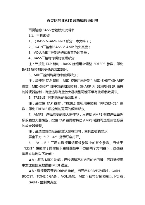
百灵达的BASS音箱模拟说明书百灵达的BASS音箱模拟说明书1.1、主机面板1、(BASS V-AMP PRO部分,本文略);2 、GAIN――控制BASS V-AMP 的失真度;3、VOLUME――控制所选预设音色的音量;4、BASS――控制均衡的低频部分;注:当按住TAP 键时,BASS 旋钮用来调整“DEEP”参数,即比BASS所控制的更低的频率部分。
5、MID――控制均衡的中低频部分;注:当按住TAP 键时,MID 旋钮用来控制”MID-SHIFT/SHARP”参数,MID-SHIFT 即中频的扫频控制,SHARP为BEHRINGER独特的滤波器控制,有些选取有些放大器模型可能不带有此项参数调节。
6、TREBLE――控制均衡的高频部分;注:当按住TAP 键时,TREBLE 旋钮用来控制“PRESENCE”参数,即比TREBLE所控制的更高的频率部分。
7、AMPS――选择需要的放大器模型,只转动AMPS 钮将选择白色标识的放大器模型,按住TAP 键同时转动AMPS 钮将可选择灰色标识的放大器模型。
注:当选取灰色标识的放大器模型时,主机面板的显示屏坐下方“17-32”指示灯会打开。
8、“A ~E ”――用来选择每组预设参数中的某个参数。
当处于“EDIT”模式时(同时按下主机面板中下方的两个方向键),这些键将用来控制以下功能:▲A:激活MIDI 功能,通过调整左右方向的方向键,可以选择用来发送和接受数据的MIDI 通道。
▲B:选择是否开启DRIVE 功能。
当开启DRIVE功能时,GAIN、BOOST、TONE(GAIN、VOLUME、MID)钮将分别控制以下功能:GAIN-控制失真度BOOST-控制“DRIVE”部分的音量TONE-模拟失真类单快效果器的“TONE”控制在此部分功能中包含了模拟的一些著名的单块效果器的音色。
注:当DRIVE 功能激活时,调节EFFECTS MIX 参数可以用来控制Wah-Wah 效果。
百灵达V-amp2.0使用说明书
天津风格琴行 V-AMP 2 清洁: 请按照手册的说明进行清洁。 长期不使用: 如果长期不使用应该拔下电源线。 避免液体或碎屑进入: 注意避免碎屑或各种液体流入效果器内部。 维修: 出现下列情况请找专业人士进行维修 --电源或其他插孔接触不良; --有液体或者碎屑进入机内; --被雨淋湿 --操作或显示不正常 维修服务: 用户不要进行手册没有标明的维修,请联系专业维修人员。
8.2 MIDI 控制参数表
2.5 连接功放系统和舞台监听的演出模式 9 性能参数
3 V-AMP2 储存音色
3.1 调出已存储的音色
3.2 编辑音色
3.3 储存音色
3.4 抛弃一个已编辑音色/恢复原厂音色
3.5 恢复所有原厂音色
4 AMP/音箱模拟介绍
4.1 被模拟的 AMP 特性描述
4.2 被模拟的音箱类型
1.2.1 用户界面
7.1 音频连接插头
1.2.2 V-AMP2 侧面板的接口
7.2 MIDI 连接
2 不同模式的使用范例
7.2.1 发送/接收 MIDI
2.1 选择输出模式
数据
2.2 基本的吉他,踏板开关和外部回放 8 附录
2.3 录音模式
8.1 默认 AMP/音箱搭配
2.4 外接吉他功率放大器的演出模式
____________________________________________________________________
前言
天津风格琴行 V-AMP 2
亲爱的顾客: 欢迎您成为 BEHRINGER 用户的一员并感谢您通过购买 V-AMP2 所表示的
百灵达音频处理器说明书DEQ2496

GEQ 图形均衡器PEQ 参数均衡器DEQ 动态均衡器WIDTH音像宽广调整FBD 回授抑制DYN 动态处理UTILITY 各项设定选单I / O 输入输出功能BYPASS功能不使用开关MEMORY 储存功能METER 表头RTA 音场实时分析模式在使用此手册之前,请了解说明是依官方操作方式进行,不过在一些功能页面皆包括了一些快速按键的使用,操作者在熟悉基本的运作调整后,自然对于快速使用的功能按键会有一番的认识,而在此不再详述。
2. CONTROL ELEMEENTS ( 控制组件)。
2.1 Front panel ( 正面的面版)。
1. LED METER ( 表头指示)。
指示输入的声音讯号电平大小,在其最上方的灯号是CLIP ( 讯号切割) 的指示,表示输入的讯号已经过大,或是在DYN (动态处理)的调整上,其LIMITER( 限制器) 设定限制电平位置过低的原因,参照章节 3.4。
2. METER key ( 表头按键)。
使用这个按键进入后,可以选择三种不同的表头指示模式,参照章节3.10。
3. RTA key ( 音场实时分析模式按键)。
使用这个按键进入后,可以选择三种不同的分析显示,参照章节 3.8。
4. COMPARE ( 功能调整比较按键)。
使用这个按键进入后,可以将你预设的储存资料来与当下所调整的数据来做两种比较。
5. MEMORY key ( 记忆储存按键)。
在这里,你可以将DEQ - 2496 所调整后的数据储存起来,以方便下次的呼叫使用,参照章节 3.9。
图 2 - 1 各项按键显示图 2 - 2 各项按键显示与飞梭旋转控制定义。
6. PAGE key ( 页面选择按键)。
当你是在某项的功能页面时,藉由这个按键再去选择里面的章节出来做调整。
7. functions performed key ( 功能定义执行按键)。
藉由上方的动作后,欲去执行当下的模式或是型态,或改变设定回复预设等,这个功能按键区分 A 键、B 键,是一个去完成的指令键。
压限器的使用方法

压限器的使用方法(申精)因为这个问题始终困绕着我,后来在搜了许多关于压限器的文章,整理出来,给跟我一样的新手.在这里我说两句:这只是先人给的一点技术,要想摸透,还是自己动手研究.顾名思义,压限器就是压缩器和限制器的组合体,压缩器的含义就是说要保证后级设备输出的一定要小于前级设备的输入,而限制器的含义就是无论前级设备的电平输入有多大,但是经过限制器处理后传到后级设备,他的电平输出一定要保持限制器设定的那个恒定的量。
压限器的功能有很多,主要有六点:减小动态冲击。
录音过程中压缩动态。
平衡音量。
保护功放、音箱等。
制作特殊效果。
减小非音乐信号中的噪声。
调试过程中:1、THRESHOLD门限电平。
调节压限器开始工作的电平值,输入高于此值,压限器开始工作,一般不应超过0dB。
2、RATIO压限比动态信号被压缩的量。
如打到2:1时,输入为超过门限电平40dB输出公为20dB,也就是动态被压缩了1/2.一般当门限为0dB时,压限比应为10:1。
当门限为-20dB时,压缩比建议为2:1以上。
在的士高舞厅如果压缩比设定过小,就没有压缩痕迹;如果压缩比设定过大,就会造成音乐动态范围变窄、声音干瘪无味。
在的士高厅扩声中作为压缩器使用,一般将压缩比设定在3:1左右,作为限制器使用时,应将压缩比设定在8:1左右.能保证音乐信号压缩在扩声系统的动态范围内,避免过载失真,以确保的士高舞厅音乐的震撼力。
3,ATTACK压缩起动时间.压限器从输入信号到压缩开始之间的量(时间)。
为保护功放,应最小。
4、RELEASE 压缩恢复时间.压限器从压缩状态恢复到原始状态的时间。
为使声音充满一些生气,建议为适中。
5、INPUT OUTPUT 输入、输出电平量。
建议为0dB6、GAIN REDUCTION 输入衰减量。
7、STEREO LINK 连锁按键。
双声道处理时,当按下此键,可使门限由一个通道控制。
8、BYPASS 压限使用/旁路。
音频压限器在晚会中的使用音频压限器是一种大压缩比,高阈值电平的信号动态压缩装置,它主要用于抑制有输入信号的意外大峰值冲击而造成设备的过载失真,其压缩比一般在10:1至20:1之间,阈值电平则由输入电路的动态范围来确定。
百灵达V-AMP说明书
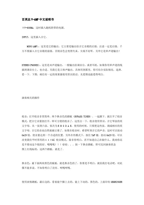
百灵达V-AMP中文说明书9V-600MA:这时插入随机附带的电源。
INPUT:这里插入吉它。
MONO(AMP):这里是它的输出,它主要是输出给吉它音箱的后级,注意一定是后级,千万不要插入吉它音箱的前级,否则音色会变得失真、尖锐不好听。
另外它是单声道输出!STEREO(PHONES):这里是双声道输出,一般输出给调音台,或者耳机,如果你用单声道的线插到调音台上,也合适。
另我它是立体声输出,具体用到那里,你可结合实际情况,选择。
看一下,下图,相信有一定的效果器使用常识的话,光看图也能看得明白。
演奏相关的操作校音:打开校音非常简单,两个换音色的踏板(BYPASS/TUNER),一起踏下,就打开了校音模式,把吉它音量扭打开,即可方便的校音了,这里注一下,校音使用常识,吉它琴弦的英文字母,从一弦到六弦,依次为E B G D A E,使用的时候,只要把这些弦,调成相应的英文字母,吉它的音高自然就被订准了。
如果在校音时,希望听到吉它的声音,这时可以扭动GAIN钮,使音量达到一个合适的位置。
另外在些模式下,按住TAP键,扭动GAIN钮,可以改变我们平时常用的440HZ校音模式,除非你明白,若不知道自己在做什么,我劝你还是不要动这个钮的好。
嘎嘎嘎!!!@@,,,按一下换音踏板,即可反回演奏状态图上红线标的,这两个踏板,就是了。
换音色:最下面两块黑色的板板,就是换音色的了,你要是不明白,就给我打电话吧,对此偶不能多说。
不知你明白了没有。
呵嘎呵嘎。
使用表情踏板:最右边的,看着能个脚上去的,能上下动的,黑色的,上面印有GEHRINGER的LOGO的,踏板,就是表情踏板了。
使用它的时候,要看一眼下图那个地方是什么模式。
这里有一个红颜色的灯,会表示目前在那一个模式上,WAH:代表哇音,VOLLME:代表音量EFFECT:代表打开或关闭效果SPEED:代表一个值。
比如晃动的快慢等。
这四种模式只有在WAH模式下,需要开启外,其它都不需要,往下往上踏,即会产生作用。
音台百灵达调音台使用图解说明
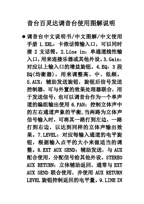
音台百灵达调音台使用图解说明调音台中文说明书/中文图解/中文使用手册1.XRL:卡侬话筒输入口,可以同时接2支话筒。
2.Line in:单通道线性输入口,用来连接乐器或其他外设。
3.Gain:对应以上输入口的增益旋钮。
4.EQ:3段EQ(均衡器),用来调整高、中、低频。
5.AUX:辅助发送旋钮,旋钮后信号发送控制器,可与外置的效果处理器联合,用于发送信号;也可以调音台作为一个单声道的编组输出使用6.PAN:控制立体声中的左右通道声象的平衡,当两路为立体声信号输入时,可将其一路打到左边,一路打到右边,以达到同样的立体声输出效果。
7.LEVEL:对应每输入通道的电平旋钮,根据输入点平的大小来做适当的调整。
8.EXT AUX SEND:辅助发送,与AUX 配合使用,分配信号给其他外设。
STEREO AUX RETURN:立体辅助返回,通常与EXT AUX SEND联合使用,并使用AUX RETURN LEVEL旋钮控制返回的电平量。
9.LINE IN3/4,5/6:立体声线性输入,此立体声分为左右声道,可同时使用。
10.PHONES:鉴听耳机插口。
11.MAIN MIX OUT:调音台的主混音输出接口,一般用此输出连接到主要的后级设备上。
12.2 TRACK:用于输出信号到DAT,MD或者是硬盘录音系统或者接收这些设备的返送信号;与下边的2TK TO MIX和2TK TO CTRL ROOM联合使用,可以实现简单的编组输出功能。
13.CTRL RM OUT:控制室鉴听输出接口,连接到控制室鉴听设备,也可作为普通的鉴听输出。
14.混响效果器:内置100个28比特(bit)数码效果。
PRESS to SELECT:内置效果的选择旋钮。
EFFECTS LEVEL:效果量电平控制旋钮。
15.辅助功能:AUX RETURN LEVEL:辅助返回信号电平控制旋钮,即控制从STEREO AUX RETURN返回的电平信号。
Omega FPB1400 Paddle Wheel 流量计用户指南说明书

e-mail:**************For latest product manuals: FPB1400Paddle Wheel Meter Shop online at User’sG uid e***********************Servicing North America:U.S.A. Omega Engineering, Inc.Headquarters: Toll-Free: 1-800-826-6342 (USA & Canada only)Customer Service: 1-800-622-2378 (USA & Canada only)Engineering Service: 1-800-872-9436 (USA & Canada only)Tel: (203) 359-1660 Fax: (203) 359-7700e-mail:**************For Other Locations Visit /worldwideThe information contained in this document is believed to be correct, but OMEGA accepts no liability for any errors it contains, and reserves the right to alter specifications without notice.TABLE OF CONTENTS1.UNPACKING THE PADDLE WHEEL METER...................................1.1Inspect Package for External Damage..............................................1.2 Unpack the Paddle Wheel Meter.......................................................1.3 Returning Merchandise for Repair.....................................................2.FPB1400 PADDLE WHEEL METERS........................................2.1 Principles of Operation.....................................................................3.SPECIFICATIONS................................................................4.PARTS............................................................................5.INSTALLATION...................................................................6.MAINTENANCE.................................................................6.1Sensors..............................................................................................6.2Paddle Wheel Disassembly. (1)11111234444The selection of materials of construction, is the responsibility of the customer. The company accepts no liability.1.UNPACKING THE FPB14001.1 Inspect Package for External DamageY our was carefully packed in a sturdy cardboard carton, with anti-static cushioning materials to withstand shipping shock. Upon receipt, inspect the package for possible external damage. In case of external damage to the package contact the shipping company immediately.Remove the Packing List and verify that you have received all equipment. If you have any questions about the shipment, please call the Omega TM Customer Service Department at 1-800-622-2378 or (203) 359-1660. Y our FPB1400 Paddle Wheel Meter was carefully packed in a sturdy cardboard carton, with anti-static cushioning materi-als to withstand shipping shock. Upon receipt, inspect the package for possible exter-nal damage. In case of external damage to the package contact the shipping compa-ny immediately.1.2Unpack the Paddle Wheel MeterOpen the carton carefully from the top and inspect for any sign of concealed shipping damage. In addition to contacting the shipping carrier please forward a copy of any damage report to Omega TM directly. When unpacking the instrument please make sure that you have all the items indicated on the Packing List. Please report any shortages promptly.1.3 Returning Merchandise for RepairPlease contact an Omega TM customer service representative and request a Return Authorization Number (AR). It is mandatory that any equipment returned for servicing be purged and neutralized of any dangerous contents including but not limited to toxic,bacterially infectious, corrosive or radioactive substances. No work shall be performed on a returned product unless the customer submits a fully executed, signed SAFETY CERTIFICATE. Safety form can be obtained from Omega TM Customer Service.2.FPB1400 PADDLE WHEEL METERS2.1 Principles of OperationFPB1400 liquid flow meters consist of a meter body that is installed in-line in a conduit system. Inside, between the inlet and the outlet connections is a rotary wheel with permanent magnets embedded at 180 degrees in paddles.Fluid flowing through the meter causes the paddle to spin. A magnetic sensor picks up the frequency of pulses, and the readings are proportional to the liquid flow taking place. The number of pulses per unit time interval and a K-factor (pulses/unit of flow) facilitate determining the volumetric rate of flow through the meter.13.SPECIFICATIONS24.PARTS35.INSTALLATIONNPT female inlet and outlet port sizes are shown in the table in the flow rate on the pre-ceding page.It is necessary to include an upstream straight pipe of at least five times the inside diameter of the line.Installation horizontally or vertically is acceptable.The magnetic sensor requires 5-24 VDC power (30 mA max. load).FLOW SENSOR CONNECTION CONFIGURATION:RED - 5-26 VDC power (+)BLACK - POWER(-), COMMONGREEN - SENSOR NPN OPEN COLLECTOR OUTPUT“pull-up” resistor is necessary for PLC input with current sourcing. Recommended value: 2.2 K Ohm for 24 VDC input.FPB1400 meters supplied with (four wire) RTD options are connected using the stainless steel temperature sensor adapter supplied.6.MAINTENANCE6.1SensorsIn rare instances, due to electrical damage, the pulse sensor needs to be replaced by unscrewing it and installing a replacement (hand tight).The RTD /adapter subassembly is replaceable using a wrench.6.2Paddle Wheel DisassemblyBearings are highly susceptible to careless disassembly and reassembly practices. The nickel T ungsten Shaft of the Wheel is supported at each end by sapphire bearings to minimize friction and facilitate very low flow rate measurements.The Wheel may be uninstalled by holding the Lid in place, and removing the four mounting screws, very carefully to prevent damaging the sapphire Bearings at each end of the Shaft. If the Bearings are shattered, they need to be replaced. Reassembly is made ensuring that the Shaft ends are inserted gently into the sapphire Bearings. Check to see if the wheel is free to spin before the Lid Bearing is installed. While holding the Lid in place, blow into the meter to verify that the Wheel is free to spin. Finally the Lid is reinstalled using the four mounting screws.ƽCAUTION:Never use compressed air or gases to test the meter, as thiswould damage the Bearings.4OMEGA’s policy is to make running changes, not model changes, whenever an improvement is possible. T his affords our customers the latest in technology and engineering.OMEGA is a trademark of OMEGA ENGINEERING, INC.© Copyright 2018 OMEGA ENGINEERING, INC. All rights reserved. T his document may not be copied, photocopied, reproduced, translated, or reduced to any electronic medium or machine-readable form, in whole or in part, without the prior written consent of OMEGA ENGINEERING, INC.FOR WARRANTY RETURNS, please have the following information available BEFORE contacting OMEGA:1. P urchase Order number under which the product was PURCHASED,2. M odel and serial number of the product under warranty, and3. Repair instructions and/or specific problems relative to the product.FOR NON-WARRANTY REPAIRS, consult OMEGA for current repair charges. Have the following information available BEFORE contacting OMEGA:1. Purchase Order number to cover the COST of the repair,2. Model and serial number of the product, and 3. Repair instructions and/or specific problems relative to the product.RETURN REQUESTS/INQUIRIESDirect all warranty and repair requests/inquiries to the OMEGA Customer Service Department. BEFORE RET URNING ANY PRODUCT (S) T O OMEGA, PURCHASER MUST OBT AIN AN AUT HORIZED RET URN (AR) NUMBER FROM OMEGA’S CUST OMER SERVICE DEPART MENT (IN ORDER T O AVOID PROCESSING DELAYS). The assigned AR number should then be marked on the outside of the return package and on any correspondence.T he purchaser is responsible for shipping charges, freight, insurance and proper packaging to preventbreakage in transit.WARRANTY/DISCLAIMEROMEGA ENGINEERING, INC. warrants this unit to be free of defects in materials and workmanship for a period of 13 months from date of purchase. OMEGA’s WARRANTY adds an additional one (1) month grace period to the normal one (1) year product warranty to cover handling and shipping time. This ensures that OMEGA’s customers receive maximum coverage on each product.If the unit malfunctions, it must be returned to the factory for evaluation. OMEGA’s Customer Service Department will issue an Authorized Return (AR) number immediately upon phone or written request. Upon examination by OMEGA, if the unit is found to be defective, it will be repaired or replaced at no charge. OMEGA’s WARRANT Y does not apply to defects resulting from any action of the purchaser, including but not limited to mishandling, improper interfacing, operation outside of design limits, improper repair, or unauthorized modification. T his WARRANT Y is VOID if the unit shows evidence of having been tampered with or shows evidence of having been damaged as a result of excessive corrosion; or current, heat, moisture or vibration; improper specification; misapplication; misuse or other operating conditions outside of OMEGA’s control. Components in which wear is not warranted, include but are not limited to contact points, fuses, and triacs.OMEGA is pleased to offer suggestions on the use of its various products. However, OMEGA neither assumes responsibility for any omissions or errors nor assumes liability for any damages that result from the use of its products in accordance with information provided by OMEGA, either verbal or written. OMEGA warrants only that the parts manufactured by the company will be as specified and free of defects. OMEGA MAKES NO OTHER WARRANTIES OR REPRESENTATIONS OF ANY KIND WHATSOEVER, EXPRESSED OR IMPLIED, EXCEPT THAT OF TITLE, AND ALL IMPLIED W ARRANTIES INCLUDING ANY W ARRANTY OF MERCHANTABILITY AND FITNESS FOR A PARTICULAR PURPOSE ARE HEREBY DISCLAIMED. LIMITATION OF LIABILITY: The remedies of purchaser set forth herein are exclusive, and the total liability of OMEGA with respect to this order, whether based on contract, warranty, negligence, indemnification, strict liability or otherwise, shall not exceed the purchase price of the component upon which liability is based. In no event shall OMEGA be liable for consequential, incidental or special damages.CONDITIONS: Equipment sold by OMEGA is not intended to be used, nor shall it be used: (1) as a “Basic Component” under 10 CFR 21 (NRC), used in or with any nuclear installation or activity; or (2) in medical applications or used on humans. Should any Product(s) be used in or with any nuclear installation or activity, medical application, used on humans, or misused in any way, OMEGA assumes no responsibility as set forth in our basic WARRANT Y /DISCLAIMER language, and, additionally, purchaser will indemnify OMEGA and hold OMEGA harmless from any liability or damage whatsoever arising out of the use of theProduct(s) in such a manner.Where Do I Find Everything I Need forProcess Measurement and Control?OMEGA…Of Course!Shop online at TEMPERATUREM U Thermocouple, RTD & Thermistor Probes, Connectors,Panels & AssembliesM U Wire: Thermocouple, RTD & ThermistorM U Calibrators & Ice Point ReferencesM U Recorders, Controllers & Process MonitorsM U Infrared PyrometersPRESSURE, STRAIN AND FORCEM U Transducers & Strain GagesM U Load Cells & Pressure GagesM U Displacement TransducersM U Instrumentation & AccessoriesFLOW/LEVELM U Rotameters, Gas Mass Flowmeters & Flow ComputersM U Air Velocity IndicatorsM U Turbine/Paddlewheel SystemsM U Totalizers & Batch ControllerspH/CONDUCTIVITYM U pH Electrodes, Testers & AccessoriesM U Benchtop/Laboratory MetersM U Controllers, Calibrators, Simulators & PumpsM U Industrial pH & Conductivity EquipmentDATA ACQUISITIONM U Communications-Based Acquisition SystemsM U Data Logging SystemsM U Wireless Sensors, Transmitters, & ReceiversM U Signal ConditionersM U Data Acquisition SoftwareHEATERSM U Heating CableM U Cartridge & Strip HeatersM U Immersion & Band HeatersM U Flexible HeatersM U Laboratory HeatersENVIRONMENTALMONITORING AND CONTROLM U Metering & Control InstrumentationM U RefractometersM U Pumps & TubingM U Air, Soil & Water MonitorsM U Industrial Water & Wastewater TreatmentM U pH, Conductivity & Dissolved Oxygen InstrumentsM5129/0518。
- 1、下载文档前请自行甄别文档内容的完整性,平台不提供额外的编辑、内容补充、找答案等附加服务。
- 2、"仅部分预览"的文档,不可在线预览部分如存在完整性等问题,可反馈申请退款(可完整预览的文档不适用该条件!)。
- 3、如文档侵犯您的权益,请联系客服反馈,我们会尽快为您处理(人工客服工作时间:9:00-18:30)。
百灵达MDX1400噪声门及压扩器的使用
(2009-01-08 10:30:12)
转载
标签:
文化
功能键及调节:
1、 EXOPANDER /THRESHOLD (噪声门)
噪声门(EXOPANDER/GATE)的作用是:当输入信号小于噪声门限阈值时,压限器无输出;大于噪声门阈值时,正常输出。
它可以消除声音信号间隙过程中的本低噪声。
调节方式:将噪声门旋钮置于最小位置(OFF),关闭音源,顺时针旋转旋钮,噪声门指示灯亮到绿灯即停。
门限阈值调的太大,会出现声音断尾或间断现象;调的太小,噪声门会不起作用。
2、 THRESHOLD (阈值)
阈值决定了压限器在多大电平时开始起作用。
调节方式:将阈值调到最小位置,把调音台的音量开到最大(音量提升必须在确认压缩比大于2:1后进行),然后逐渐提升阈值,当音量达到所需声压级或功放和音箱的额定功率,立即停止提升阈值。
3、 RATIO (压缩比)
压缩比是输入信号分贝数与输出信号分贝数之比,其大小决定了对输入信号的压缩程度。
如果作为压缩器使用,一般应调到3:1左右,此时,意味著输入信号每增加3分贝时输出信号才增加1分贝;作为限制器使用时,应将压缩比调到无穷大比一,此时,意味著输出信号不随著输入信号的增加而增加。
当然,压缩和限制的条件必须是输入信号的电平要超过压限器的阈值电平,否则,起不到压缩和限制的作用。
4、ATTACK (启动时间)
启动时间是输入信号超过阈值后,从不压缩状态进入到压缩状态所需要的时间。
如果压限器的启动时间长,输入信号超过阈值后要等一会儿才进入压缩状态,这会使出来的声音变硬。
如果压限器的启动时间很短,输入信号一达到阈值就立即进入压缩状态,声音则会变软。
4、 RELRASE (恢复时间)
恢复时间是当输入信号小于阈值后,从压缩状态恢复到不压缩状态所需要的时间。
5、 AUTO (自动启动时间与恢复时间)
使用此功能时,自动启动时间与恢复时间由压限器根据实际情况自动决定。
6、 OUTPUT (输出增益)
控制压限器输出电平,一般放在0db的位置,即不提升也不衰减。
7、 GAIN REDUCTRON db(增益减少指示电平)
显示压限器进入压缩状态时增益的衰减情况,共有8个发光二极管,增益衰减显示范围为0至30db。
8、 ENHANCER PROCESS(高频补偿处理)
使用此功能时,压限器在进入压缩状态后,可以自动对由于信号压缩而造成的高频损失进行补偿,不压缩时,此功能不起作用。
9、 IN/OUT(旁路)
加于不加压限选择,“IN”为加,“OUT”为不加。
在扩声系统的连接:
串接到主(左、右)通道
这种接法主要用于保护功放和音箱,此时,压限器必须放在均衡器后、功放前,如图所示:百灵达MDX1400噪声门及压扩器的使用。