脉搏传感器说明书
hk2000系列脉搏传感器数据手册
合肥华科电子技术研究所
Hefei Huake Electronic Technical Research Institute
简体中文
传感器系列
1 公司简介:
合肥华科电子技术研究所是一家以医用传感器和医疗设备为主的研发与生产型 企业,在生物体征信号的采集和无创伤亚健康检测方面推出了一系列产品,主要包 括:脉搏、心音、心电、胃肠电等方面的专用传感器;基于脉搏波分析的无创伤心 血管功能检测仪和基于胃肠体表生物电信号分析的胃肠电图仪等医疗设备。
传感器系列
HK-2000A 型脉搏传感器输出波形
主要特点: 模拟脉冲信号输出 灵敏度高 抗干扰性能力强 过载能力大 一致性好 性能稳定可靠,使用寿命长
技术指标: 电源电压:3~12V DC 压力量程:-50~+300mmHg 过载:100 倍 输出高电平:大于 VCC-1.5V 输出低电平:小于 0.2V
传感器系列
主要特点: 波形数据输出 标准 USB 或 RS-232 输出接口 灵敏度高,一致性好 抗干扰性能力强 过载能力大 性能稳定可靠,使用寿命长
技术指标: 电源电压:5~6V DC 压力量程:-50~+300mmHg 灵敏度:2000uV/mmHg 灵敏度温度系数:1×10⁻⁴/℃ 精度:0.5% 重复性: 0.5% 迟滞: 0.5% 过载:100 倍
等行业内有关脉率计算、脉搏波形采集、中医脉象诊断、心血管功能检测等方面的
应用。
HK-2000 系列脉搏传感器列表:
型号
原理
输出
HK-2000A
压电式
HK-2000脉搏传感器使用说明书

HK-2000系列集成化脉搏传感器采用高度集成化工艺,将力敏元件(PVDF 压电膜)、灵敏度温度补偿元件、感温元件、信号调理电路集成在传感器内部。
具有灵敏度高、抗干扰性能强、过载能力大、一致性好、性能稳定可靠、使用寿命长等特点。
访系列脉搏传感器具有完善的信号调理功能,用户在使用时后级不需要再加滤波等电路。
HK-2000A 型脉搏传感器输出同步于心脏搏动的脉冲信号,可以用于脉率数据的实时采集。
HK-2000B 型脉搏传感器输出完整的脉搏波电压信号,用于脉搏波分析系统,如中医脉象、心血管功能检测、妊高征检测等系统。
主要特点:1、灵敏度高。
2、抗干扰性能强。
3、过载能力大。
4、 一致性好,性能稳定可靠,使用寿命长。
技术指标:HK-2000A电源电压:5-12VDC压力量程:-50~+300mmHg过载:100倍输出高电平:大于VCC-1.5V输出低电平:小于0.2VHK-2000BU n R e g i s t e r e d电源电压:5~6VDC压力量程:-50~+300mmHg灵敏度:2000uV/mmHg灵敏度温度系数:1×10-4/℃精度:0.5%重复性: 0.5%迟滞: 0.5% 过载:100倍HK-2000A 脉搏传感器输出波形图图4 3.5标准耳机接口接口定义为尽快推广“无创心血管功能检测”技术,使其产生更大的社会和经济效益,现将我所与安徽医科大学陈国钧教授二十多年的研究成果——“心血管功能诊断仪”检测参数及专家系统计算机软件对外提供。
如有意生产“心血管功能诊断仪”的单位或个人可和我所联系,我所将提供全套技术支持。
U n R e g i s t er e d。
HKG-07B红外脉搏传感器
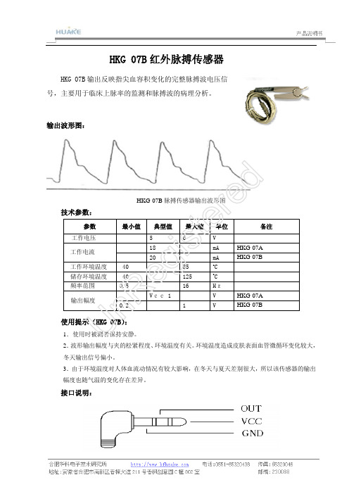
HKG-07B 红外脉搏传感器
HKG-07B 输出反映指尖血容积变化的完整脉搏波电压信号,主要用于临床上脉率的监测和脉搏波的病理分析。
输出波形图:
HKG-07B 脉搏传感器输出波形图
技术参数:
参数 最小值 典型值 最大值 单位
备注
工作电压 5 6 V
18 mA HKG-07A 工作电流 20
mA HKG-07B
工作环境温度 -40 85 o C 储存环境温度 -40 125 o
C
频率范围
0.5 16 Hz
Vcc-1
V HKG-07A 输出幅度
0.2
1
V
HKG-07B
使用提示(HKG-07B):
1.使用时被测者保持安静。
2.波形输出幅度与夹的松紧程度、环境温度有关。
环境温度造成皮肤表面血管微循环变化较大,冬天输出信号偏小。
3.由于环境温度对人体血流动情况有较大影响,在冬天与夏天差别很大,所以该传感器的输出幅度也随气温的变化存在差异。
接口说明:
U
n R
e g
i s
t e
r e
d。
保乐心率传感器H7用户手册说明书

User Manual Gebrauchsanleitung Manuel d’Utilisation Manuale d’uso Gebruiksaanwijzing Manual del Usuario Manual do utilizador BrugervejledningKäyttöohje Brukerveiledning Bruksanvisning使⽤説明書POLARH7B3B2CB1B4E N G L I S H Polar H7Heart Rate SensorThis user manual contains instructions for Polar H7heart rate sensor.The latest version of this user manual can be downloaded at /support.For video tutorials,go to/en/polar_community/videos. Register your Polar product athttp://register.polar.fi to ensure we can keep improving our products and services to better meet your needs.Please follow the pictures on the front cover. Heart Rate Sensor Parts1.The plastic electrode areas on the reverseside of the strap detect heart rate.PictureA1.2.The connector sends the heart rate signalto the receiving device.Picture A2.Polar H7heart rate sensor enables training in a group without interference from other heart rate sensors.1.Moisten the electrode areas of the strap.Picture B1.2.Attach the connector to the strap.PictureB2.3.Adjust the strap length to fit tightly butcomfortably.4.Tie the strap around your chest,just belowthe chest muscles,and attach the hook tothe other end of the strap.Picture B3.5.Check that the moist electrode areas arefirmly against your skin and that the Polarlogo of the connector is in a central andupright position.Picture B4.Detach the connector from the strap and rinsethe strap under running water after every use.Sweat and moisture may keep the electrodeswet and the heart rate sensor activated.Thiswill reduce the transmitter battery life.See detailed washing instructions in the Caring for Your Heart Rate Sensor section or at/support.Polar H7heart rate sensor is compatible with Bluetooth®smart ready devices that support heart rate service.A separate application is required to view heart rate data on the receiving device(for example,a smartphone).It is recommended to use the Polar Beat application but it is also possible to use other applications. If you have a account Polar Beat automatically synchronizes your training files to it.Please note that you must sign in to your account when starting Polar Beat for the synchronization to work.When using the Polar H7for the first time, you need to pair the heart rate sensor with your receiving device.For more information on pairing,see the mobile application manufacturer's instructions.Polar H7heart rate sensor is also compatible with Polar training computers using GymLink technology.For more information,go to /support.To ensure sufficient transmission range from your Polar H7heart rate sensor to the receiving device,keep the device in front of you.A good place is in a front pocket or fixed on a belt.Do not wear the receiving device on your back(for example,in a back pocket or backpack). Using Your Heart Rate Sensor in Water Polar H7heart rate sensor is water resistant. The GymLink technology can be used in water activities,but Bluetooth®wireless technology will not work in water.Please notice that sea and pool water are very conductive,and electrodes may short-circuit,preventing ECG signals from being detected by the heart rate sensor.When using a bathing suit,the best performance is achieved by wearing the heart rate sensor underneath it.The heart rate sensor is a high-tech instrument that should be handled with care.Follow the caring instructions to ensure reliable measurement and to maximize the life span of the heart rate sensor.The following instructions will help you fulfill guarantee obligations.Connector:Detach the connector from the strap after every use and dry the connector with a soft towel.Clean the connector with a mild soap and water solution when needed.Never use alcohol or any abrasive material (e.g.steel wool or cleaning chemicals).Strap:Rinse the strap under running water after every use and hang to dry.Clean the strap gently with a mild soap and water solution when needed.Do not use moisturizing soaps,because they can leave residue on the strap.Do not soak,iron,dry clean or bleach the strap.Do not stretch the strap or bend the electrode areas sharply.Dry and store the strap and the connector separately to maximize the heart rate sensor battery lifetime. Keep the heart rate sensor in a cool and dry place.Do not store the heart rate sensor wet in non-breathing material,such as a sports bag,to prevent snap oxidation.Do not expose the heart rate sensor to direct sunlight for extended periods.Check the label on your strap to see if it is machinewashable.Never put the strap or the connector in a dryer!The battery level of your heart rate sensor is displayed on the receiving device.All connectors have user changeable batteries.To change the battery yourself,follow the instructions below,and see the markings on the connector and picture C on the front cover of this user manual.ing a coin,open the battery cover by turning itcounterclockwise to OPEN.2.Insert the battery(CR2025)inside the cover withthe positive(+)side against the cover.Make surethe sealing ring is in the groove to ensure waterresistance.3.Press the cover back into the connector.e the coin to turn the cover clockwise toCLOSE.When changing the battery,make sure the sealing ring is not damaged,in which case you should replace it with a new one.You can purchase the sealing ring/battery kits atwell-equipped Polar retailers and authorized Polar Services.In the USA and Canada,the additional sealing rings are available at authorized Polar Service Centers.In the USA the sealing ring/battery kits are also available at .Keep batteries away from children.If swallowed,contact adoctor immediately.Batteries should be disposed of incompliance with local regulations.Caution:Risk of explosion if battery is replaced by an incorrect type.Dispose of batteries according to the instructions.ServiceDuring the two-year guarantee/warranty period we recommend that you have service,other than battery replacement,done by an authorized Polar Service Center only.The warranty does not cover damage or consequential damage caused by service not authorized by Polar Electro.For contact information and all Polar Service Center addresses,visit /support and country-specific websites.PrecautionsFor allergy information,see the listed materials in Technical Specifications.Avoid skin reactions by wearing the heart rate sensor over a shirt,moistened under the electrodes.The combined impact of moisture and intense abrasion maycause a black color to come off the heart rate sensor’ssurface,possibly staining light-colored clothes.If you useperfume or insect repellent on your skin,you must ensurethat it does not come into contact with the heart rate sensor.Battery type CR2025Battery sealing ring O-ring20.0x1.0Material FPM Battery lifetime200hOperating temperature 14°F to122°F/-10°C to +50°CConnector material PolyamideStrap material38%Polyamide,29%Polyurethane,20%Elastane,13%PolyesterThe Polar H7heart rate sensor applies the following patented technologies,among others:•OwnCode®coded transmissionLimited Polar International Guarantee•This guarantee does not affect the consumer’s statutory rights under applicable national or statelaws in force,or the consumer’s rights against the dealer arising from their sales/purchase contract.•This limited Polar international guarantee is issued by Polar Electro Inc.for consumers who havepurchased this product in the USA or Canada.This limited Polar international guarantee is issued byPolar Electro Oy for consumers who have purchased this product in other countries.•Polar Electro Oy/Polar Electro Inc.guarantees the original consumer/purchaser of this device that the product will be free from defects in material orworkmanship for two(2)years from the date ofpurchase.•The receipt of the original purchase is your proof of purchase!•The guarantee does not cover the battery,normal wear and tear,damage due to misuse,abuse,accidents or non-compliance with the precautions;improper maintenance,commercial use,cracked,broken or scratched cases/displays,armband,elastic strap and Polar apparel.•The guarantee does not cover any damage/s,losses, costs or expenses,direct,indirect or incidental,consequential or special,arising out of,or related to the product.•Items purchased second hand are not covered by the two(2)year warranty,unless otherwisestipulated by local law.•During the guarantee period,the product will be either repaired or replaced at any of the authorized Polar Service Centers regardless of the country ofpurchase.Guarantee with respect to any product will be limited to countries where the product has been initially marketed.This product is compliant with Directives1999/5/EC and2011/65/EU.The relevant Declaration of Conformity is available at /support.Compliance StatementCanadaPolar Electro Oy has not approved any changes or modifications to this device by the user.Any changes or modifications could void the user’s authority to operate the equipment.Polar Electro Oy n’a approuéaucune modification apportéeàl’appareil par l’utilisateur,quelle qu’en soit la nature.Tout changement ou toute modification peuvent annuler le droit d’utilisation de l’appareil par l’utilisateur.Industry Canada(IC)regulatory informationThis device complies with Industry Canadalicence-exempt RSS standard(s).Operation is subject to the following two conditions:(1)this device may not cause interference,and(2)this device must accept any interference,including interference that may cause undesired operation of the device.Avis de conformitéàla réglementation d’Industrie CanadaLe présent appareil est conforme aux CNR d'Industrie Canada applicables aux appareils radio exempts de licence.L'exploitation est autorisée aux deux conditions suivantes:(1)l'appareil ne doit pas produire de brouillage,et(2)l'utilisateur de l'appareil doit accepter tout brouillage radioélectrique subi,même si le brouillage est susceptible d'en compromettre le fonctionnement.Class B digital device noticeThis Class B digital apparatus complies with Canadian ICES-003,RSS-Gen and RSS-210.Cet appareil numérique de la classe B est conformeàla norme NMB-003,CNR-Gen et CNR-210du Canada.USAPolar Electro Oy has not approved any changes or modifications to this device by the user.Any changes or modifications could void the user’s authority to operate the equipment.FCC regulatory informationThis device complies with part15of the FCC rules. Operation is subject to the following two conditions:(1) This device may not cause harmful interference,and (2)This device must accept any interference received, including interference that may cause undesired operation.Note:This equipment has been tested and found tocomply with the limits for a Class B digital device, pursuant to part15of the FCC Rules.These limits are designed to provide reasonable protection against harmful interference in a residential installation.This equipment generates,uses and can radiate radio frequency energy and,if not installed and used in accordance with the instructions,may cause harmful interference to radio communications.However,there is no guarantee that interference will not occur in a particular installation.If this equipment does cause harmful interference to radio or television reception,which can be determined by turning the equipment off and on,the user is encouraged to try to correct the interference by one or more of the following measures:1.Reorient or relocate the receiving antenna.2.Increase the separation between the equipmentand receiver.3.Connect the equipment into an outlet on a circuitdifferent from that to which the receiver isconnected.4.Consult the dealer or an experienced radio/TVtechnician for help.This product emits radio frequency energy,but the radiated output power of this device is far below the FCC radio frequency exposure limits.This equipment complies with FCC RF radiation exposure limits forth for an uncontrolled environment.Nevertheless,the device should be used in such a manner that the potential for human contact with the antenna during normal operation is minimized.This crossed out wheeled bin marking shows that Polar products are electronic devices and are in the scope of Directive2002/96/EC of the European Parliament and of the Council on waste electrical and electronic equipment(WEEE)and batteries and accumulators used in products are in the scope of Directive2006/66/EC of the European Parliament and of the Council of6September2006on batteries and accumulators and waste batteries and accumulators. These products and batteries/accumulators inside Polar products should thus be disposed of separately in EU countries.This marking shows that the product is protected against electric shocks.Copyright2016Polar Electro Oy,FI-90440KEMPELE, Finland.Polar Electro Oy is a ISO9001:2008certified company.All rights reserved.No part of this manual may be used or reproduced in any form or by any means without prior written permission of Polar Electro Oy.The names and logos marked with a™symbol in this user manual or in the package of this product are trademarks of Polar Electro Oy.The names and logos marked with a®symbol in this user's manual or in the package of this product are registered trademarks of Polar Electro Oy. The Bluetooth®word mark and logos are registered trademarks owned by Bluetooth SIG,Inc.and any useof such marks by Polar Electro Oy is under license. DisclaimerPolar Electro Inc./Polar Electro Oy disclaims any and all liabilities related to or arising from third parties' products or services,which use the data generated by a Polar product.Polar Electro Inc./Polar Electro Oy disclaims any and all liabilities related to or arising from the functioning/malfunctioning of third party product or service,its interoperability with a Polar product,safety of a third party product or service as well as any other liabilities related to or arising from a third party product or service.Polar Electro Inc./Polar Electro Oy shall not be liable for any data transfer fees or any other fees which might be due to or related to the use of this Polar product.This product is protected by the incorporeal rights of Polar Electro Oy as defined by the following documents: FI96380,EP0665947,US5611346,JP3568954,EP1543769,US7418237.Other patents pending.Compatible with Gym LinkManufactured by Polar Electro Oy Professorintie 5FI-90440 KEMPELE Tel +358 8 5202 100 Fax +358 8 5202 300。
医用传感器(心电脑电脉搏波)指导书(09)
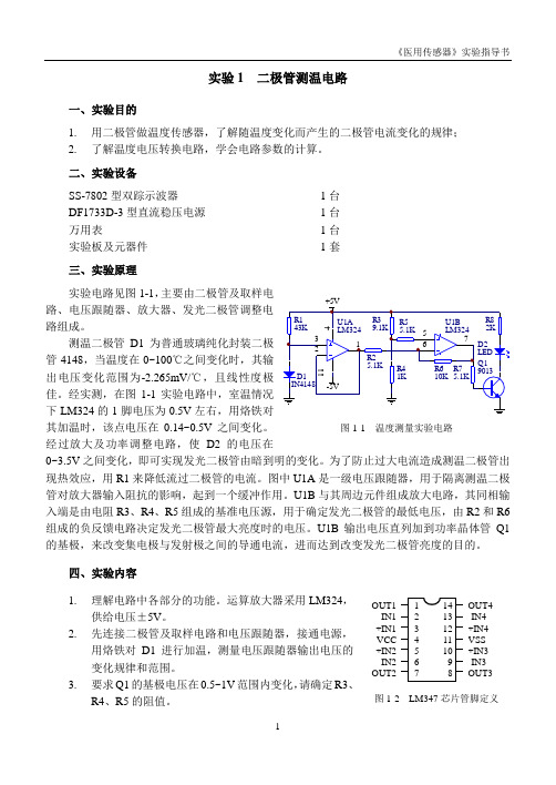
实验1 二极管测温电路一、实验目的1. 用二极管做温度传感器,了解随温度变化而产生的二极管电流变化的规律;2. 了解温度电压转换电路,学会电路参数的计算。
二、实验设备SS-7802型双踪示波器 1台 DF1733D-3型直流稳压电源 1台 万用表 1台 实验板及元器件 1套三、实验原理实验电路见图1-1,主要由二极管及取样电路、电压跟随器、放大器、发光二极管调整电路组成。
测温二极管D1为普通玻璃纯化封装二极管4148,当温度在0~100℃之间变化时,其输出电压变化范围为-2.265mV/℃,经实测,在图1-1实验电路中,室温情况下LM324的1脚电压为0.5V 左右,用烙铁对其加温时,该点电压在0.14~0.5V 之间变化。
经过放大及功率调整电路,使D2的电压在0~3.5V之间变化,即可实现发光二极管由暗到明的变化。
为了防止过大电流造成测温二极管出现热效应,用R1来降低流过二极管的电流。
图中U1A 是一级电压跟随器,用于隔离测温二极管对放大器输入阻抗的影响,起到一个缓冲作用。
U1B 与其周边元件组成放大电路,其同相输入端是由电阻R3、R4、R5组成的基准电压源,用于确定发光二极管的最低电压,由R2和R6组成的负反馈电路决定发光二极管最大亮度时的电压。
U1B 输出电压直列加到功率晶体管Q1的基极,来改变集电极与发射极之间的导通电流,进而达到改变发光二极管亮度的目的。
四、实验内容1. 理解电路中各部分的功能。
运算放大器采用LM324,供给电压±5V 。
2. 先连接二极管及取样电路和电压跟随器,接通电源,用烙铁对D1进行加温,测量电压跟随器输出电压的变化规律和范围。
3. 要求Q1的基极电压在0.5~1V 范围内变化,请确定R3、R4、R5的阻值。
图1-2 LM347芯片管脚定义OUT1-IN1 +IN1VCC+IN2-IN2OUT2OUT4 -IN4 +IN4 VSS +IN3 -IN3 OUT34.连接其余电路,接通电源,进行调试。
电子脉搏计操作流程

电子脉搏计操作流程
1. 准备工作
- 确保电子脉搏计已经充电或连接到电源供电。
- 检查脉搏计的传感器是否清洁并正确安装。
2. 打开脉搏计
- 按下电源按钮,通常位于脉搏计的侧面或顶部。
- 等待脉搏计启动,并确保显示屏正常工作。
3. 设置测量参数
- 根据需要,设置脉搏计的测量参数。
例如,测量时长、自动关机时间等。
4. 准备测量位置
- 找到要测量的位置,通常是手腕或手指。
- 紧贴脉搏计的传感器部分放置在测量位置上。
5. 进行测量
- 根据脉搏计的指示,轻轻将测量位置与传感器接触。
- 确保位置稳定,并保持相对静止。
- 等待脉搏计完成测量,通常会有声音或震动提示。
6. 查看测量结果
- 在脉搏计的显示屏上查看测量结果。
- 注意脉搏率、血压等指标,根据需要记录或显示给使用者。
7. 清理和存储
- 使用干净的布或纸巾擦拭脉搏计的外表面。
- 将脉搏计放置在干燥、整洁的地方,以防止损坏或灰尘积累。
以上为电子脉搏计的操作流程,务必遵循相应的安全规定和使
用说明书,以确保正确操作和获得准确的测量结果。
PA18C.T 通脉感应传感器说明说明书
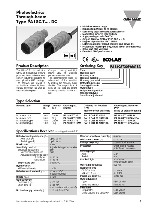
Product DescriptionThe PA18C.T... is part of a family of inexpensive general purpose through-beam sen-sors in industrial standard 18 mm cylindrical ABS housing. The sensors are useful in applications where high-ac-curacy detection as well as small size is required.Compact housing and highperformance-size ratio.The potentiometer used for adjustment of the sensitivi-ty makes the sensors highly flexible. The output type is NPN or PNP and the output switching function is NO and NC.• Miniature sensor range• Range: 20 m (Axial), 16 m (Radial)• Sensitivity adjustment by potentiometer • Modulated, infrared light 850 nm • Supply voltage: 10 to 30 VDC• Output: 100 mA, NPN or PNP, N.O + N.C.• Degree of protection IP67, IP69K• LED indication for output, stability and power ON• Protection: reverse polarity, short circuit and transients • Cable and plug versions • Excellent EMC performancePhotoelectrics Through-beamType PA18C.T..., DCType SelectionHousing type Range Connec- Ordering no. Ordering no. Receiver Ordering no. Receiver S n tion Emitter N P N P N PMake or break switching Make or break switchingM18 Axial type 20 m Cable PA 18 CAT 20 PA 18 CAT 20 NASA PA 18 CAT 20 PASA M18 Axial type 20 m Plug PA 18 CAT 20M1 PA 18 CAT 20 NAM1SA PA 18 CAT 20 PAM1SA M18 Radial type 16 m Cable PA 18 CRT 16 PA 18 CRT 16 NASA PA 18 CRT 16 PASA M18 Radial type16 mPlugPA 18 CRT 16M1PA 18 CRT 16 NAM1SAPA 18 CRT 16 PAM1SASpecifications Receiver according to EN60947-5-2PA18C.T...Specifications Common according to EN60947-5-2Operation DiagramOperation DiagramPower supply OFF ON Target (emitter)Present Make Output (N.O.)OFFON Break Output (N.C.)OFF ONObjectPresent tv = Power ON delay* The IP69K test according to DIN 40050-9 for high-pressure, high-temperature wash-down applications.The sensor must not only be dust tight (IP6X), but also able to withstand high-pressure and steam cleaning. The sensor is exposed to high pressure water from a spray nozzle that is fed with 80°C water at 8’000– 10’000 KPa (80–100bar) and a flow rate of 14–6L/min. The nozzle is held 100 –150 mm from the sensor at angles of 0°, 30°, 60° and 90° for 30s each. The test device sits on a turntable that rotates with a speed of 5 times per minute. The sensor must not suffer any damaging effects from the high pressure water in appea-rance and function.90°60°30°0°Specifications Emitter according to EN60947-5-2PA18C.T...Wiring DiagramsDetection DiagramExcess GainPA18C.T...Dimensions Radial versionPA18C.T...Dimensions Axial versionSignal Stability IndicationAPA18-MB1Delivery Contents• Photoelectric switch: PA 18 C.T...• Installation instruction on plastic bag • Screwdriver• Mounting bracket APA18-MB1• 2 M18 locknuts• P ackaging: Plastic bag• Emitter and receiver is packed separatelyTo avoid interference from inductive voltage /current peaks, separate the proximity switch cables from any other power cables. E.g.Engine, contactor or solenoid cablesIncorrectCorrectThe cable should not be pulledA proximity switch should not serve as mechanical stopRelief of the cable strain Protection of the sensing face Incorrect> 100 mmCorrect IncorrectInstallation HintsAccessories• Connector type CONG1A.. / CONM14NF.. seriesPA18C.T...Mounting SystemsPA18 mounting with a combination of 1 x APA18-MB1 and 1 x M18 locknut.Maximum torque 0.9 NMPA18 mounting with a combination of 2 x M18 locknuts. Maximum torque 2.0 NMAPA18-MB1APA18-MB1M18 LocknutM18 Locknut.0 m m . 4.5 m m。
CONTEC 脉搏血氧探头使用说明书
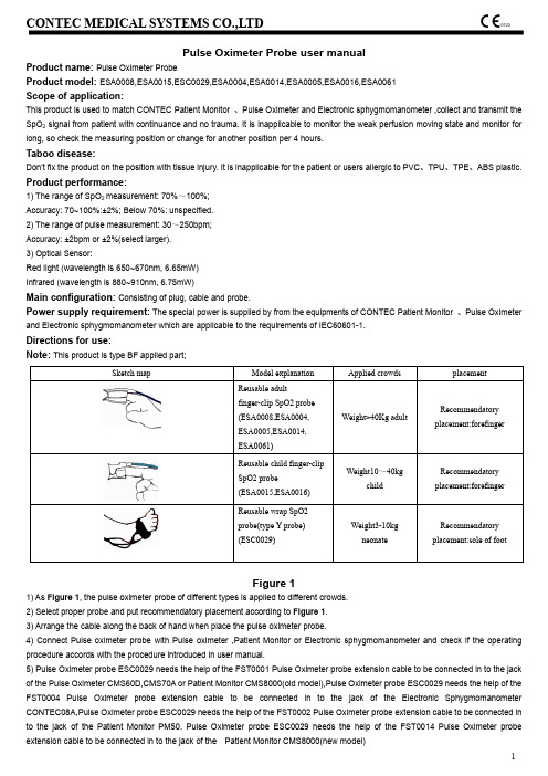
Pulse Oximeter Probe user manualProduct name: Pulse Oximeter ProbeProduct model: ESA0008,ESA0015,ESC0029,ESA0004,ESA0014,ESA0005,ESA0016,ESA0061 Scope of application:This product is used to match CONTEC Patient Monitor 、Pulse Oximeter and Electronic sphygmomanometer ,collect and transmit the SpO 2 signal from patient with continuance and no trauma. It is inapplicable to monitor the weak perfusion moving state and monitor for long, so check the measuring position or change for another position per 4 hours.Taboo disease:Don't fix the product on the position with tissue injury. It is inapplicable for the patient or users allergic to PVC 、TPU 、TPE 、ABS plastic.Product performance:1) The range of SpO 2 measurement: 70%~100%; Accuracy: 70~100%:±2%; Below 70%: unspecified. 2) The range of pulse measurement: 30~250bpm; Accuracy: ±2bpm or ±2%(select larger). 3) Optical Sensor:Red light (wavelength is 650~670nm, 6.65mW) Infrared (wavelength is 880~910nm, 6.75mW)Main configuration: Consisting of plug, cable and probe.Power supply requirement: The special power is supplied by from the equipments of CONTEC Patient Monitor 、Pulse Oximeterand Electronic sphygmomanometer which are applicable to the requirements of IEC60601-1.Directions for use:Note: This product is type BF applied part;Figure 11) As Figure 1, the pulse oximeter probe of different types is applied to different crowds. 2) Select proper probe and put recommendatory placement according to Figure 1. 3) Arrange the cable along the back of hand when place the pulse oximeter probe.4) Connect Pulse oximeter probe with Pulse oximeter ,Patient Monitor or Electronic sphygmomanometer and check if the operating procedure accords with the procedure introduced in user manual.5) Pulse Oximeter probe ESC0029 needs the help of the FST0001 Pulse Oximeter probe extension cable to be connected in to the jack of the Pulse Oximeter CMS60D,CMS70A or Patient Monitor CMS8000(old model),Pulse Oximeter probe ESC0029 needs the help of the FST0004 Pulse Oximeter probe extension cable to be connected in to the jack of the Electronic Sphygmomanometer CONTEC08A,Pulse Oximeter probe ESC0029 needs the help of the FST0002 Pulse Oximeter probe extension cable to be connected in to the jack of the Patient Monitor PM50. Pulse Oximeter probe ESC0029 needs the help of the FST0014 Pulse Oximeter probe extension cable to be connected in to the jack of the Patient Monitor CMS8000(new model)Sketch mapModel explanation Applied crowdsplacementReusable adult finger-clip SpO2 probe (ESA0008,ESA0004, ESA0005,ESA0014, ESA0061)Weight>40Kg adultRecommendatory placement:forefingerReusable child finger-clip SpO2 probe(ESA0015,ESA0016)Weight10~40kgchildRecommendatory placement:forefingerReusable wrap SpO2 probe(type Y probe) (ESC0029)Weight3-10kg neonateRecommendatory placement:sole of footNotice items:1) pulse oximeter probe placement, the position without ductus arteriosus, BP cuff and vein input pipe is top-priority.2) If the pulse oximeter probe can't monitor the state of pulsation, it shows that the position of probe is improper, or the position is too thick, too thin or having too deep pigment to reach a proper translucidus effect. If above things has happened, place the probe again or select probe of other type.3) This pulse oximeter probe should be applied to the special medical equipment. Operator is responsible to check the compatibility Incompatible fittings or device will influence the measuring result.4) The disposal of scrap instrument and its accessories and packing (including battery, plastic bags, foams and paper boxes) should follow the local laws and regulations.Maintenance/cleaning/disinfection:1) Check if the product is undamaged and clean before using.2) This product is not allow to use disinfection liquid for disinfection, this probe belong to one-off products.Note: Don't immerse the product in the liquid, and don't expose it under the strong ultra-violet radiationService life: Suggest this product use only once, don't use again.Environment requirements:Transport and storage1) Temperature: -10℃~+40℃2) Humidity: less than 80%3) Pressure:86kPa~106kPaOperating1) Temperature: 10℃~+40℃2) Humidity: 30% ~ 75%3) Pressure: 700hPa~1060PaStatement:1) pulse oximeter probe needs special precautions regarding EMC and needs to be installed and put into service according to theEMC information provided in User Manual and test report.2) Portable and mobile RF communications equipment can affect pulse oximeter probe.Warning:1) The use of cables other than those specified, with the exception of cables sold by CONTEC as replacement parts for internal components, may result in increased emissions or decreased immunity of pulse oximeter probe.2) pulse oximeter probe should not be used adjacent to or stacked with other equipment and that if adjacent or stacked use is necessary, the pulse oximeter probe should be observed to verify normal operation in the configuration in which it will be used.3) Improper usage can result in inaccurate measurement.4) Using it under too strong light will cause inaccurate measurement, in case of that, please set a opaque stuff around the probe to cut light off.5) You should move the probe to other position per 4 hours at least. Because the state of local skin can influence the ability of skin to enduring probe, it is necessary to replace the position of probe according to the state of patient. Please do that when skin integrity changes.6) The dyestuff in blood vessel cab cause the inaccurate measurement.7) The performance of pulse oximeter probe is influenced by movement easily, so it is not suitable for active patient to use it.8) Don't fix the probe with belt or bundle it tightly, because the vein pulsation can cause inaccurate SpO2 measurement.9) Same as other medical equipment, the cable should be set properly to avoid enlacing or asphyxiate patient.10) Don't use it in the process of MRI scan, because the conductor current may burn the skin of patient, moreover, the probe willinfluence MRI image and MRI set will also influence the accuracy of SpO2 measurement.11) Don't change the product at will, otherwise the capability or accuracy of product will be influenced.12) The probe is not intended for use during patient transport outside the healthcare facility.13) DO NOT use the probe while the patient is being scanned by MRI or CT.Explanation about graphs and symbols used on the product:Followinstructionsfor useDate ofmanufactureKeep awayfrom sunlightKeep in acool, dryplaceTYPE BFAPPLIEDPARTProductcodeWEEEdisposalIPX1CoveringProtectionrate Lot number SpO2The pulseoximetersaturation(%)BPM Pulse rate(bpm)ManufacturerAuthorized representativein the community EuropeanMedical Device complieswith Directive 93/42/EECGuidance and manufacturer’s declaration – electromagnetic emissions-forpulse oximeter probeGuidance and manufacturer’s declaration – electromagnetic emissionThe pulse oximeter probe is intended for use in the electromagnetic environment specified below. The customer of the user of the pulse oximeter probe should assure that it is used in such and environment.Emission testCompliance Electromagnetic environment – guidanceRF emissions CISPR 11Group 1The pulse oximeter probe uses RF energy only for its internal function. Therefore, its RF emissions are very low and are not likely to cause any interference in nearby electronic equipment.RF emission CISPR 11Class B The pulse oximeter probe is suitable for use in all establishments, including domestic establishments and those directly connected to the public low-voltage power supply network that supplies buildings used for domestic purposes.Harmonic emissions IEC 61000-3-2Not ApplicableVoltage fluctuations/ flicker emissions IEC 61000-3-3Not ApplicableGuidance and manufacture’s declaration – electromagnetic immunity –for pulse oximeter probeGuidance and manufacture’s declaration – electromagnetic immunityThe pulse oximeter probe is intended for use in the electromagnetic environment specified below. The customer or the user of pulse oximeter probe should assure that it is used in such an environment.Immunity testIEC 60601 test levelCompliance levelElectromagnetic environment - guidanceElectrostatic discharge (ESD) IEC 61000-4-2 ±6 kV contact ±8 kV air±6 kV contact ±8 kV airFloors should be wood, concrete or ceramic tile. If floor are covered with synthetic material, the relative humidity should be at least 30%.Power frequency (50/60Hz) magneticfield IEC61000-4-83A/m 3A/m Power frequency magnetic fields Should be at levels characteristic of a typical location in a typical commercial or hospital environment.Guidance and manufacturer’s declaration – electromagnetic immunity –forpulse oximeter probe that are not LIFE-SUPPORTINGGuidance and manufacturer’s declaration – electromagnetic immunityThe pulse oximeter probe is intended for use in the electromagnetic environment specified below. The customer or the user of pulse oximeter probe should assure that it is used in such an environment.Immunity test IEC 60601 test level CompliancelevelElectromagnetic environment - guidanceConducted RF IEC 61000-4-6Radiated RF IEC 61000-4-3 3Vrms150 kHz to 80 MHz3 V/m80 MHz to 2.5 GHz3 V3 V/mPortable and mobile RF communications equipmentshould be used no closer to any part of the pulseoximeter probe, including cables, than therecommended separation distance calculated fromthe equation applicable to the frequency of thetransmitter.Recommended separation distancePd2.1=Pd2.1=80 MHz to 800 MHzPd3.2=800 MHz to 2.5 GHzWhere P is the maximum output power rating of thetransmitter in watts (W) according to the transmittermanufacturer and d is the recommended separationdistance in metres (m).Field strengths from fixed RF transmitters, asdetermined by an electromagnetic site survey,a shouldbe less than the compliance level in each frequencyrange.bInterference may occur in the vicinity of equipmentmarked with the following symbol:NOTE 1 At 80 MHz and 800 MHz, the higher frequency range applies.NOTE 2 These guidelines may not apply in all situations. Electromagnetic propagation is affected by absorption and reflection from structures, objects and people.a Field strengths from fixed transmitters, such as base stations for radio (cellular/cordless) telephones and land mobile radios, amateur radio, AM and FM radio broadcast and TV broadcast cannot be predicted theoretically with accuracy. To assess the electromagnetic environment due to fixed RF transmitters, an electromagnetic site survey should be considered. If the measured field strength in the location in which the pulse oximeter probe is used exceeds the applicable RF compliance level above, the pulse oximeter probe should be observed to verify normal operation. If abnormal performance is observed, additional measures may be necessary, such as reorienting or relocating the pulse oximeter probe.b Over the frequency range 150 kHz to 80 MHz, field strengths should be less than 3 V/m.Recommended separation distances between portable and mobileRF communications equipment and pulse oximeter probe–for pulse oximeter probe that are not LIFE-SUPPORTINGRecommended separation distances betweenportable and mobile RF communications equipment and the pulse oximeter probeThe pulse oximeter probe is intended for use in an electromagnetic environment in which radiated RF disturbances are controlled. The customer or the user of the pulse oximeter probe can help prevent electromagnetic interference by maintaining a minimum distance between portable and mobile RF communications equipment (transmitters) and the pulse oximeter probe as recommended below, according to the maximum output power of the communications equipment.Rated maximum output power of transmitter(W)Separation distance according to frequency of transmitter(m)150 kHz to 80 MHzPd2.1=80 MHz to 800 MHzPd2.1=800 MHz to 2.5 GHzPd3.2=0.01 0.120.120.230.1 0.370.370.741 1.17 1.17 2.3310 3.69 3.697.38100 11.6711.6723.33For transmitters rated at a maximum output power not listed above, the recommended separation distance d in metres (m) can be estimated using the equation applicable to the frequency of the transmitter, where P is the maximum output power rating of the transmitter in watts (W) according to the transmitter manufacturer.NOTE 1 At 80 MHz and 800 MHz, the separation distance for the higher frequency range applies.NOTE 2 These guidelines may not apply in all situations. Electromagnetic propagation is affected by absorption and reflection from structures, objects and people.Shanghai International Holding Corp. GmbH (Europe) Address: Eiffestrasse 80, 20537, Hamburg, GermanyTel: +49-40-2513175Fax: +49-40-255726E-mail: *********************File No.: CMS2.782.G002(CE)ESS/1.6File V er.: 1.6Release Date: 2020.06CONTEC MEDICAL SYSTEMS CO., LTDAddress: No.112 Qinhuang West Street, Economic&Technical Development Zone,066004,Qinhuangdao,Hebei Province,PEOPLE'S REPUBLIC OF CHINATel: +86-335-8015430Fax: +86-335-8015430E-mail:*****************.cn。
- 1、下载文档前请自行甄别文档内容的完整性,平台不提供额外的编辑、内容补充、找答案等附加服务。
- 2、"仅部分预览"的文档,不可在线预览部分如存在完整性等问题,可反馈申请退款(可完整预览的文档不适用该条件!)。
- 3、如文档侵犯您的权益,请联系客服反馈,我们会尽快为您处理(人工客服工作时间:9:00-18:30)。
主要特点:
波形数据输出 标准 USB 接口 灵敏度高,一致性好 抗干扰性能力强 过载能力大 性能稳定可靠,使用寿命长
技术指标:
参数 压力范围 最大压力 工作温度范围 储存温度范围 线性度 重量 外 感应面直径 形长 尺宽 寸
厚
最小值
-40 -40 -0.3
典型值 5.8
20 13 40 15 8
HK-2000G
压阻(电阻)式
模拟信号,输出完整的脉搏波电压信号
HK-2000H
压阻(电阻)式
数字信号,输出与 PC 机接口的脉搏波数据
HKG-07A
光电式
模拟信号,输出同步于脉搏波动的脉冲信号
合肥华科电子技术研究所
电话:0551-5320046,3310968
(3) Typ. value (3) Typ. value
备注:
1. 如无特别说明本表所有数值皆在以下测试条件下测得,驱动电压 5 Vdc,25±3℃,相对湿 度 25﹪~85﹪。
2. 最佳匹配线性。
3. 典型温度特性数值,其溫度范围为 0oC 到 50 oC 之间。
合肥华科电子技术研究所
电话:0551-5320046,3310968
合肥华科电子技术研究所
电话:0551-5320046,3310968
第2页
2.2 HK-2000B 集成化脉搏传感器
HK-2000B 集成化脉搏传感器采用高度集成化工艺将 力敏元件(PVDF 压电膜)、灵敏度温度补偿元件、感温元件、 信号调理电路集成在传感器内。压电式原理采集信号,模 拟信号输出,输出完整的脉搏波电压信号,该产品主要应 用于无创心血管功能检测、妊高征检测、中医脉象诊断等。
电气特性:
参数
最小值 典型值 最大值 单位
备注
一般特性
压力范围 最大压力 工作温度范围 储存温度范围 重量 尺寸
5.8
PSI
2X
-40
125
oC
-40
125
oC
g
¢16x6
mm × mm
额定压力 -40 oF ~+257oF -40 oF ~+257 oF
电气性能(1)
驱动电压要特点: 波形数据输出 标准 USB 或 RS-232 输出接口 灵敏度高,一致性好 抗干扰性能力强 过载能力大 性能稳定可靠,使用寿命长
技术指标: 电源电压:5~6V DC 压力量程:-50~+300mmHg 灵敏度:2000uV/mmHg 灵敏度温度系数:1×10⁻⁴/℃ 精度:0.5% 重复性: 0.5% 迟滞: 0.5% 过载:100 倍
合肥华科电子技术研究所
电话:0551-5320046,3310968
第3页
2.3 HK-2000C 集成化数字脉搏传感器
HK-2000C 集成化数字脉搏传感器是在 HK-2000B 的基础 上增加了程控放大电路、基线调整电路、A/D 转换电路、串 行通信电路,方便用户集成及二次开发使用。压电式原理 采集信号,数字信号输出,直接通过 USB 或串口输出脉搏 波波形数据,该产品可应用于脉率检测、无创心血管功能 检测、妊高征检测、中医脉象诊断等。
产品特点: 模拟电压信号输出 输出高保真、低阻抗、音频信号 集成度高,可靠性好 过载能力达到 100 倍 抗干扰性能力强
技术参数: 电源:3-5V DC 功耗:5mA 频率响应: 1-600Hz 灵敏度: 大于 4mV/Pa 输出信号幅度:0.5-1.5V
典型应用电路:
第7页
传感器系列
3 心音传感器
HKY 系列心音传感器采用新型高分子聚合材料微音传感元件采集心脏搏动和其
它体表动脉搏动信号,再经过高度集成化信号处理电路处理。高保真输出,稳定性、
一致性好。产品可广泛应用于各类心音采集设备。
HKY 系列心音传感器列表:
型号
输出信号
功能特点
应用领域
HKY-06A 功率信号,可驱动耳机
传感器系列
合肥华科电子技术研究所
电话:0551-5320046,3310968
第9页
传感器系列
3.2 HKY-06B 型心音传感器
HKY-06B 型心音传感器采用新型高分子聚合材料微音传感元件采集心脏搏动和 其它体表动脉搏动信号,再经过高度集成化信号处理电路处理。输出低阻抗音频信 号。采用模块化设计,PCB 插件方式封闭。可广泛应用于各类心音采集设备,如心音 信号采集、胎音信号采集以及其它体表微音信号采集。
第1页
2.1 HK-2000A 集成化脉搏传感器
HK-2000A 集成化脉搏传感器采用高度集成化工艺将 力敏元件(PVDF 压电膜)、灵敏度温度补偿元件、感温元 件、信号调理电路集成在传感器内。压电式原理采集信号, 模拟信号输出,输出同步于脉搏波动的脉冲信号,脉搏波 动一次输出一正脉冲。该产品可用于脉率检测,如运动、 健身器材设备中的心率测试。
最大值
2X 125 125 0.30
单位 PSI
oC oC % Span g mm mm mm mm
备注
额定压力 -40 oF ~+257oF -40 oF ~+257 oF
集成应用: HK-2000H 集成化数字脉搏传感器 + 心血管功能检测软件 = 心血管功能检测仪。 有意生产“心血管功能检测仪”及其相关产品的厂家可和我单位联系,我所可提供全 套技术支持!
传感器系列
主要特点: 模拟电压信号输出 灵敏度高 抗干扰性能力强 过载能力大 一致性好 性能稳定可靠,使用寿命长
技术指标: 电源电压:5~6V DC 压力量程:-50~+300mmHg 灵敏度:2000uV/mmHg 灵敏度温度系数:1×10⁻⁴/℃ 精度:0.5% 重复性: 0.5% 迟滞: 0.5% 过载:100 倍
等行业内有关脉率计算、脉搏波形采集、中医脉象诊断、心血管功能检测等方面的
应用。
HK-2000 系列脉搏传感器列表:
型号
原理
输出
HK-2000A
压电式
模拟信号,输出同步于脉搏波动的脉冲信号
HK-2000B
压电式
模拟信号,输出完整的脉搏波电压信号
HK-2000C
压电式
数字信号,输出与 PC 机接口的脉搏波数据
传感器系列
2.4 HK-2000G 集成化数字脉搏传感器
HK-2000G 压阻式脉搏传感器可由电压或电流驱动产 生正比于输入压力的毫伏等级的电压输出信号,具有优 异的可重复性和时间稳定性。该产品体积小巧,非常适 合于脉率检测、无创心血管功能检测、妊高征检测、中 医脉象诊断等领域的集成应用。
产品特点: 模拟电压信号输出 高度集成化,体积小巧 可靠性高,使用寿命长 灵敏度高
5
15
Vdc
1.5
3
mA
4
5
6
kΩ
-25
0
25
mV
满量程输出电压 5.8 PSI) 50
75
100
mV
线形度 零点漂移温度系数
-0.3 -0.08
0.30
% Span
(2)
0.08 % Span/oC
(3)
全量程温度系数 电阻温度系数
-0.16
-0.21(4) ±0.05(5)
0.20
-0.26
%Span/ oC %/ oC
医用传感器简介 Medical Sensors Introduction
合肥华科电子技术研究所
Hefei Huake Electronic Technical Research Institute
简体中文
传感器系列
1 公司简介:
合肥华科电子技术研究所是一家以医用传感器和医疗设备为主的研发与生产型 企业,在生物体征信号的采集和无创伤亚健康检测方面推出了一系列产品,主要包 括:脉搏、心音、心电、胃肠电等方面的专用传感器;基于脉搏波分析的无创伤心 血管功能检测仪和基于胃肠体表生物电信号分析的胃肠电图仪等医疗设备。
单电源供电型应用
双电源供电型应用
合肥华科电子技术研究所
电话:0551-5320046,3310968
第 10 页
传感器系列
3.3 HKY-06C 型心音传感器
HKY-06C 型心音传感器采用新型高分子聚合材料微音传感元件采集心脏搏动和其 它体表动脉搏动信号,再经过高度集成化信号处理电路处理、A/D 转换、USB 通信电 路等,输出数字音频信号。该产品适用于各类基于电脑的心音诊断或心音图谱分析 系统。
合肥华科电子技术研究所
电话:0551-5320046,3310968
第6页
传感器系列
2.6 HKG-07A 红外脉搏传感器
HKG-07A 红外脉搏传感器利用红外线检测由于心脏跳动而引起的手指尖内微血 管容积发生的变化,经过信号放大、调理、整形输出同步于脉搏跳动的脉冲信号, 从而计算出脉率。主要用于临床上脉率的测量、监测等。
2 脉搏传感器
HK-2000 系列集成化脉搏传感器,采用高度集成化工艺将力敏元件(PVDF 压电
膜)、灵敏度温度补偿元件、感温元件、信号调整电路集成在传感器内。具有灵敏度
高、抗干扰性能力强、过载能力大、一致性好、性能稳定、使用寿命长等特点。
HK-2000 系列集成化脉搏传感器主要适用于体育、教育、科研、医疗卫生、保健
第5页
传感器系列
2.5 HK-2000H 集成化数字脉搏传感器
HK-2000H 集成化数字脉搏传感器是在 HK-2000G 的基础上增加了程控放大电路、 信号调理电路、A/D 转换电路、滤波电路、串行通信电路等,方便用户集成及二次开 发使用。该产品采用高度集成化工艺,体积小巧、使用寿命长,具有优异的可重复 性和时间稳定性。尤其适合中医脉象诊断之用,以及无创心血管功能检测、妊高征 检测等应用。