Ultra-low-loss optical fiber nanotapers
Mellanox MC6709309 8光纤到4双LCs(2光纤)活动光纤分裂器线缆说明说明书

©2017 Mellanox Technologies. All rights reserved.†For illustration only. Actual products may vary.Mellanox ® MC6709309 is an MPO (8 fibers) to 4 duplex LCs (2 fibers) passive optical splitter cable designed for 100GbE to 4 x 25GbE cable assemblies connections, for example. Connecting this optical cable to Mellanox QSFP and SFP transceivers provides connectivity between devices using a QSFP port on one end and multiple SFP ports on the other end.The fiber assembly, also referred to as a “splitter cable” or “breakout cable”, enables splitting the 4 channels in a quad-channel multi-mode transceiver into 4 separate single channels. This is used in data centers to link Top-of-Rack QSFP switch ports to single channel SFP ports in switches, servers, storage or other network appliances.Rigorous cable production testing ensures best out-of-the-box installation experience, performance and durability. Mellanox optical solutions provide short, medium and long range scalability for all topologies, utilizing innovative optical technologies to enable extremely high signal integrity and reliability.NOTE: Mellanox’s MC6709309 cables require special switch configuration. For more information, refer to the HW User Manual of the relevant switch and to the Mellanox-OS User Manual.Table 1 - Cable Insertion Loss (Attenuation)Note: LC return loss (reflection) ≥ 25dB.Table 2 - Cable Length MeasurementMC6709309-xxxINTERCONNECT PRODUCT BRIEF†8 Fiber MPO to 4 x 2 Fiber MPO Duplex LCs Passive Optical Splitter Cable350 Oakmead Parkway, Suite 100, Sunnyvale, CA 94085Tel: 408-970-3400 • Fax: © Copyright 2017. Mellanox Technologies. All rights reserved.Mellanox and Mellanox logo are registered trademarks of Mellanox Technologies, Ltd.LinkX is a trademark of Mellanox Technologies, Ltd. All other trademarks are property of their respective owners.Mellanox 8 Fiber MPO to 4 x 2 Fiber Duplex LC Passive Optical Splitter Cablepage 2Warranty InformationMellanox optical cables include a 1-year limited hardware warranty, which covers parts repair or replacement.Mechanical Schematics53988PB Rev 1.1Table 3 - Part Numbers and DescriptionsFigure 1. Channel Scheme。
异步采样全保偏光纤光梳系统研制
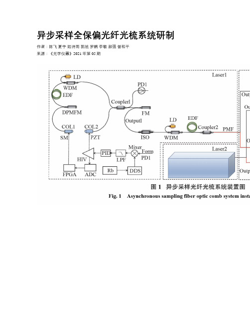
异步采样全保偏光纤光梳系统研制作者:陈飞夏宇陆诗雨郭旭罗鹏李敏郝强曾和平来源:《光学仪器》2021年第05期摘要:为了获得长期稳定的光梳光源,利用压电陶瓷(PZT)和步进电机双级反馈控制方案,研制了两台基于非线性放大环形镜(NALM)锁模的异步采样光纤光梳系统。
研究表明:该系统重复频率为75 MHz,5 min内重复频率的锁定峰峰值为±2 mHz,标准差为0.70 mHz,90 h内锁定峰峰值为±10 mHz,标准差为1.26 mHz;光纤光梳输出端口的脉冲平均功率为30 mW,经3 m保偏单模光纤压缩后脉冲宽度约为90 fs;激光器的重复频率差Δf在1 Hz~500 kHz范围内连续可调,当异步采样频差Δf为80 Hz时,扫描周期为12.5 ms,可探测出信噪比为6.3的太赫兹信号。
该方案避免使用传统机械延迟线,具有重复频率差精确可调、采样速度快、抗干扰能力强等优点。
关键词:异步采样;重复频率锁定;非线性放大;太赫兹中图分类号:TN 249文献标志码:ADevelopment of asynchronous sampling full polarization maintaining fiber optical comb systemCHEN Fei1,XIA Yu1,LU Shiyu1,GUO Xu1,LUO Peng2,LI Min1,HAO Qiang1,2,ZENG Heping3(1. School of Optical-Electrical and Computer Engineering,University of Shanghai for Science and Technology,Shanghai 200093,China;2. Guangdong Langyan Technology Co.,Ltd.,Dongguan 523000,China;3. State Key Laboratory of Precision Spectroscopy,East China Normal University,Shanghai 200062,China)Abstract:In order to obtain a long-term stable optical comb light source,two asynchronous sampling fiber optical comb systems based on nonlinear amplifying loop mirror (NALM)mode locking were developed by using piezoelectric ceramics (PZT)and a stepper motor two-stage feedback control scheme. The research shows that the system has a repetition rate of 75 MHz,thelocked peak-to-peak value of the repetition rate within 5 min is ±2 mHz,the standard deviation is 0.70 mHz,the locked peak-to-peak value within 90 h is ±10 mHz and the standard deviation is 1.26 mHz. The average power of the pulse at the comb output port is 30 mW,and the pulse width is about 90 fs after compression by 3 m polarization-maintaining single-mode fiber. The laser repetition rate difference Δf is continuously adjustable in the range of 1 Hz to 500 kHz,when asynchronous sampling. When the frequency difference Δf is 80 Hz,the scanning period is 12.5 ms,and a terahertz signal with a signal-to-noise ratio of 6.3 can be detected. This scheme avoids the use of traditional mechanical delay lines,and has the advantages of accurate and adjustable repetition rate difference,fast sampling speed,and strong anti-interference ability.Keywords:asynchronous sampling;repetition rate locking;nonlinear amplification;terahertz引言隨着太赫兹时域光谱技术(THz-TDS)与仪器的飞速发展,使其在化学、材料学、工程学、医学等领域逐步进入实用阶段[1-5]。
SYSTIMAX HD和UD ULL纤线面板解决方案指南说明书
For high- and ultra high-density fiber environments with ultra low-loss capabilitiesSYSTIMAX ®HD and UD ULL fiber panels solution guide·Modular design makes moves, adds and changes (MACs) simple·Migrate from 10G through 25Gto 40/100G parallel without expanding the footprint·Modular design offers more flexibility and allows for incremental spending as needed·Available in LazrSPEED OM4 and OM5 Wideband and TeraSPEED to support current and future high-performance applications·Utilizes same footprint for duplex LCand MPO connections·Intuitive, flexible labeling solutions foreasy port identification·Large, translucent window providesclear view of the patching field·Supports imVision automatedinfrastructure management (AIM)solution·Split-tray design provides easyinstallation while minimizing networkdowntime·Tool-less install of rear trunkcables significantly reduces trunkdeployment time·Utilizes common modules across theUD/HD platformUD/HD solution comparisonPanel Adapter types Ports/RULC/MPOMax. fiber countHD 1U Duplex LC/MPO48/3296/768HD 2U Duplex LC/MPO96/64192/1536HD 4U Duplex LC/MPO192/128384/3072UD 2U Duplex LC/MPO144/96288/2304UD 4U Duplex LC/MPO288/192576/4608iPatch HD 1U Duplex LC/MPO48/3296/768iPatch HD 2U Duplex LC/MPO96/64192/1536iPatch UD 2U Duplex LC/MPO144/96288/2304 SCALABLE MANAGEABLE AGILESYSTIMAX® HD and UD ULL fiber panels solution guide 34 SYSTIMAX ®HD and UD ULL fiber panels solution guideMATERIAL IDPRODUCT CODEDESCRIPTION760209940HD-1U SYSTIMAX HD 1U sliding fiber panel, accepts (4) G2 ULL modules or MPO panels, providing up to 48 duplex LC ports or up to 32 MPO ports760209957HD-2U SYSTIMAX HD 2U sliding fiber panel, accepts (8) G2 ULL modules or MPO panels, providing up to 96 duplex LC ports or up to 64 MPO ports760209965HD-4U SYSTIMAX HD 4U sliding fiber panel, accepts (16) G2 ULL modules or MPO panels, providing up to 192 duplex LC ports or up to 128 MPO ports760210732HD-1U-FX SYSTIMAX HD 1U fixed fiber panel, accepts (4) G2 ULL modules or MPO panels, providing up to 48 duplex LC ports or up to 32 MPO ports760210740HD-2U-FX SYSTIMAX HD 2U fixed fiber panel, accepts (8) G2 ULL modules or MPO panels, providing up to 96 duplex LC ports or up to 64 MPO ports760210757HD-4U-FX SYSTIMAX HD 4U fixed fiber panel, accepts (16) G2 ULL modules or MPO panels, providing up to 192 duplex LC ports or up to 128 MPO ports760231506HD-1U-SP SYSTIMAX HD 1U Sliding fiber panel, accepts (4) 360G2 pigtail cassettes or 360DP panels, providing field term/splice capability up to 48 duplex LC ports 760231514HD-2U-SP SYSTIMAX HD 2U Sliding fiber panel, accepts (8) 360G2 pigtail cassettes or 360DP panels, providing field term/splice capability up to 96 duplex LC ports 760231522HD-4U-SPSYSTIMAX HD 4U Sliding fiber panel, accepts (12) 360G2 pigtail cassettes or 360DP panels, providing field term/splice capability up to 192 duplex LC portsSYSTIMAX HD panelsSTEP 1: SELECT PANELS AND ACCESSORIESSYSTIMAX ® HD and UD ULL fiber panels solution guide 5MATERIAL IDPRODUCT CODEDESCRIPTION760227306UD-2U SYSTIMAX UD 2U sliding fiber panel, accepts (12) G2 ULL modules or MPO panels, providing up to 144 duplex LC ports or up to 96 MPO ports760227314UD-4U SYSTIMAX UD 4U sliding fiber panel, accepts (24) G2 ULL modules or MPO panels, providing up to 288 duplex LC ports or up to 192 MPO ports760218461UD-2U-FX SYSTIMAX UD 2U fixed fiber panel, accepts (12) G2 ULL modules or MPO panels, providing up to 144 duplex LC ports or up to 96 MPO ports760218479UD-4U-FXSYSTIMAX UD 4U fixed fiber panel, accepts (24) G2 ULL modules or MPO panels, providing up to 288 duplex LC ports or up to 192 MPO portsMATERIAL IDPRODUCT CODEDESCRIPTION760207944HD-1U-REAR-EXT 1U Rear cable extension 760207951HD-1U-REAR-COVER 1U Rear blanking panel 760209627HD-2U-REAR-EXT -06-KIT 2U Rear cable extension760209981HD-4U-REAR-EXT -06-KIT 4U Rear cable extension—6 cable entries 760209999HD-4U-REAR-EXT -12-KIT 4U Rear cable extension—12 cable entries 760209619CABLE-MOUNT -KIT -12Cable attachment molding x 12760211078HD-1U-REAR-DOOR-COVER 1U Rear door760210286HD-2U-REAR-DOOR 2U Rear door 760210294HD-4U-REAR-DOOR 4U Rear door760032110MODG2-MGS G2 Modular MGS bezel (package of 4)760109462360G2-MOD-BLANK-4PKSYSTIMAX 360G2 Mod Panel Blank, 4 Panels760058677RMB-6-1/2 InstaPATCH Plus attachment bracket, rack mounted, six 1/2" fittings 760058685RMB-6-3/8 InstaPATCH Plus attachment bracket, rack mounted, six 3/8" fittings 760225920UD-2U-REAR-EXT -06-KIT 2UD Rear cable extension—6 cable entries 760236812UD-2U-REAR-EXT -12-KIT 2UD Rear cable extension—12 cable entries 760225938UD-4U-REAR-EXT -06-KIT 4UD Rear cable extension—6 cable entries 760225946UD-4U-REAR-EXT -12-KIT4UD Rear cable extension—12 cable entriesSYSTIMAX UD panelsSYSTIMAX HD/UD panel accessoriesMATERIAL ID PRODUCT CODE DESCRIPTION760217463HD-iP-1U-32-MPO-DP-SD HD iPatch enabled 1U 32-MPO distribution panel, sliding shelf 760217471HD-iP-2U-64-MPO-DP-SD HD iPatch enabled 2U 64-MPO distribution panel, sliding shelf760236401HD-iP-1U-96F-LC-DM08-ULL-LS-SD HD iPatch enabled 1U 96F-LC distribution MPO08 ULL module, LazrSPEED OM4, sliding shelf760236400HD-iP-1U-96F-LC-DM08-ULL-WB-SD HD iPatch enabled 1U 96F-LC distribution MPO08 ULL module, LazrSPEED OM5 Wideband, sliding shelf760236405HD-iP-1U-96F-LC-DM12-ULL-LS-SD HD iPatch enabled 1U 96F-LC distribution MPO12 ULL module, LazrSPEED OM4, sliding shelf760236404HD-iP-1U-96F-LC-DM12-ULL-WB-SD HD iPatch enabled 1U 96F-LC distribution MPO12 ULL module, LazrSPEED OM5 Wideband, sliding shelf760236409HD-iP-1U-96F-LC-DM24-ULL-LS-SD HD iPatch enabled 1U 96F-LC distribution MPO24 ULL module, LazrSPEED OM4, sliding shelf760236408HD-iP-1U-96F-LC-DM24-ULL-WB-SD HD iPatch enabled 1U 96F-LC distribution MPO24 ULL module, LazrSPEED OM5 Wideband, sliding shelf760236403HD-iP-2U-192F-LC-DM08-ULL-LS-SD HD iPatch enabled 2U 192F-LC distribution MPO08 ULL module, LazrSPEED OM4, sliding shelf760236402HD-iP-2U-192F-LC-DM08-ULL-WB-SD HD iPatch enabled 2U 192F-LC distribution MPO08 ULL module, LazrSPEED OM5 Wideband, sliding shelf760236407HD-iP-2U-192F-LC-DM12-ULL-LS-SD HD iPatch enabled 2U 192F-LC distribution MPO12 ULL module, LazrSPEED OM4, sliding shelf760236406HD-iP-2U-192F-LC-DM12-ULL-WB-SD HD iPatch enabled 2U 192F-LC distribution MPO12 ULL module, LazrSPEED OM5 Wideband, sliding shelf760236411HD-iP-2U-192F-LC-DM24-ULL-LS-SD HD iPatch enabled 2U 192F-LC distribution MPO24 ULL module, LazrSPEED OM4, sliding shelf760236410HD-iP-2U-192F-LC-DM24-ULL-WB-SD HD iPatch enabled 2U 192F-LC distribution MPO24 ULL module, LazrSPEED Wideband, sliding shelfSYSTIMAX iPatch panelsSTEP 1: CONTINUEDThe SYSTIMAX® iPatch® HD & UD fiber panels are a component of the imVision® automated infrastructure management (AIM) solution and provide intelligent connectivity to the data center.·Pa nels come pre-configured with Me thod B Enhanced ULL modulesSYSTIMAX iPatch HD Panels6 SYSTIMAX® HD and UD ULL fiber panels solution guideSYSTIMAX ® HD and UD ULL fiber panels solution guide 7·G2 ULL DM modules feature unpinned, rear MPO adapters to accept ULL MPO24, MPO12 or MPO8 preterminated trunk assemblies ·Shutters automatically actuated by connector insertion, allowing for one-handed operation ·Latch assist simplifies module removal for faster moves, adds and changes (MACs) ·Shutters designed to avoid ferrule contact during connector installation·Shutter door will illuminate when exposed to a visual fault locator (VFL) for easier circuit tracing ·Utilizing Method B Enhanced polarity maintenance, the ULL modules that all transmit and receive paths are correctly routed in parallel applications Note: AIM-compatible modules and preconfigured shelves available. iPatch modules do notuse internal shutters.STEP 2: SELECT MODULES AND ADAPTER PANELSMATERIAL IDPRODUCT CODEDESCRIPTION760236362UD-iP-2U-96-MPO-DP-SDUD iPatch enabled 2U 96-MPO distribution panel, sliding shelf760236367UD-iP-2U-288F-LC-DM08-ULL-LS-SD UD iPatch enabled 2U 288F-LC distribution MPO08 ULL module, LazrSPEED OM4, sliding shelf760236366UD-iP-2U-288F-LC-DM08-ULL-WB-SD UD iPatch enabled 2U 288F-LC distribution MPO08 ULL module, LazrSPEED OM5 Wideband, sliding shelf 760236369UD-iP-2U-288F-LC-DM12-ULL-LS-SD UD iPatch enabled 2U 288F-LC distribution MPO12 ULL module, LazrSPEED OM4, sliding shelf760236368UD-iP-2U-288F-LC-DM12-ULL-WB-SD UD iPatch enabled 2U 288F-LC distribution MPO12 ULL module, LazrSPEED OM5 Wideband, sliding shelf 760236371UD-iP-2U-288F-LC-DM24-ULL-LS-SD UD iPatch enabled 2U 288F-LC distribution MPO24 ULL module, LazrSPEED OM4, sliding shelf760236370UD-iP-2U-288F-LC-DM24-ULL-WB-SDUD iPatch enabled 2U 288F-LC distribution MPO24 ULL module, LazrSPEED OM5 Wideband, sliding shelfSYSTIMAX iPatch enabled UD panels8 SYSTIMAX ®HD and UD ULL fiber panels solution guideMATERIAL ID PRODUCT CODEDESCRIPTION760236109DM08-24LC-WB-ULL G2 ULL MPO-8 distribution module, 24LC to 3x8f MPOs unpinned, LazrSPEED OM5 Wideband internal shutter760236108DM08-24LC-LS-ULL G2 ULL MPO-8 distribution module, 24LC to 3x8f MPOs unpinned, LazrSPEED OM4 internal shutter760236111DM12-24LC-WB-ULL G2 ULL MPO-12 distribution module, 24LC to 2x12f MPOs unpinned, LazrSPEED OM5 Wideband internal shutter760236110DM12-24LC-LS-ULL G2 ULL MPO-12 distribution module, 24LC to 2x12f MPOs unpinned, LazrSPEED OM4 internal shutter760236113DM24-24LC-WB-ULL G2 ULL MPO-24 distribution module, 24LC to 1x24f MPO unpinned, LazrSPEED OM5 Wideband internal shutter760236112DM24-24LC-LS-ULL G2 ULL MPO-24 distribution module, 24LC to 1x24f MPO unpinned, LazrSPEED OM4 internal shutter760238082DM08-24LC-SM-ULL G2 ULL MPO-8 distribution module, 24LC to 3x8f MPOs unpinned, TeraSPEED SM internal shutter760238083DM12-24LC-SM-ULLG2 ULL MPO-12 distribution module, 24LC to 2x12f MPOs unpinned, TeraSPEED SM internal shutterG2 ULL internal shuttered modulesG2 ULL MPO-8 distribution module, 24LC to 3x8f MPOs unpinned, LazrSPEED OM5 Wideband dust caps iPatch readySYSTIMAX ® HD and UD ULL fiber panels solution guide 9MATERIAL ID PRODUCT CODEDESCRIPTION760216754360DPis-24LC-LS 360 LazrSPEED OM4 distribution panel, 24 LC, internal shutter, aqua760236041360DPis-24LC-WB 360 LazrSPEED OM5 Wideband distribution panel, 24 LC, internal shutter, lime green 760216762360DPis-24LC-SMSYSTIMAX 360 Distribution Panel 12 LC TeraSPEED BlueSYSTIMAX 360 internal shuttered adapter panelsMATERIAL ID PRODUCT CODEDESCRIPTION760107490 360DP-2MPO 360 2-MPO adapter panel 760107508 360DP-4MPO 360 4-MPO adapter panel 760107516 360DP-6MPO 360 6-MPO adapter panel 760107524360DP-8MPO360 8-MPO adapter panelSYSTIMAX 360 MPO distribution panelsNote: Internal shutters are not compatible with iPatch. For iPatch compatible modules, see below.MATERIAL ID PRODUCT CODEDESCRIPTION760115907360DP-24LC-LS 360 LazrSPEED OM4 distribution panel, 24 LC, iPatch ready, external shutter, aqua 760236042 360DP-24LC-WB 360 LazrSPEED OM5 Wideband distribution panel, 24 LC, iPatch ready, external shutter, lime green760216762360DPis-24LC-SMSYSTIMAX 360 Distribution Panel 12 LC TeraSPEED BlueSYSTIMAX 360 iPatch ready adapter panelsMATERIAL ID PRODUCT CODE DESCRIPTION760237217CM12-2x3-LS-ULL G2 ULL 2x3 LazrSPEED OM4 Conversion Module, (2) MPO-12 unpinned ports rear, (3) MPO-8 pinned front760237220CM12-4x6-LS-ULL G2 ULL 4x6 LazrSPEED OM4 Conversion Module, (4) MPO-12 unpinned ports rear, (6) MPO-8 pinned front760237218CM12-2x3-WB-ULL G2 ULL 2x3 LazrSPEED OM5 Wideband Conversion Module, (2) MPO-12 unpinned ports rear, (3) MPO-8 pinned front760237221CM12-4x6-WB-ULL G2 ULL 4x6 LazrSPEED OM5 Wideband Conversion Module, (4) MPO-12 unpinned ports rear, (6) MPO-8 pinned front760237216CM12-2X3-SM-ULL G2 ULL 2x3 TeraSPEED SM Conversion Module,(2) MPO-12 unpinned ports rear, (3) MPO-8 pinned front760237219CM12-4X6-SM-ULL G2 ULL 4x6 TeraSPEED SM Conversion Module,(4) MPO-12 unpinned ports rear, (6) MPO-8 pinned front760237222CM24-1x3-LS-ULL G2 ULL 1x3 LazrSPEED OM4 Conversion Module, (1) MPO-24 unpinned ports rear, (3) MPO-8 pinned front760237224CM24-2x6-LS-ULL G2 ULL 2x6 LazrSPEED OM4 Conversion Module, (2) MPO-24 unpinned ports rear, (6) MPO-8 pinned front760237223CM24-1x3-WB-ULL G2 ULL 1x3 LazrSPEED OM5 Wideband Conversion Module, (1) MPO-24 unpinned ports rear, (3) MPO-8 pinned front760237225CM24-2x6-WB-ULL G2 ULL 4x6 LazrSPEED OM5 Wideband Conversion Module, (2) MPO-24 unpinned ports rear, (6) MPO-8 pinned frontG2 ULL conversion modules·G2 ULL CM modules have unpinned rear MPO adapters for to accept ULL MPO24 or MPO12 preterminated trunk assemblies and pinned front MPO adapters to accept ULL MPO8 patch cords·New latch assist provides easier module removal for faster moves, adds and changes (MAC’s)·Utilizing Method B Enhanced polarity maintenance, the ULL modules guarantee that all transmit and receive paths are correctly routed in parallel applications10 SYSTIMAX® HD and UD ULL fiber panels solution guideSYSTIMAX ® HD and UD ULL fiber panels solution guide11·8-, 12- and 24-fiber MPO connector-based modules available in LazrSPEED 550 OM4 and LazrSPEED OM5 Wideband multimode fiber solutions·8- and 12-fiber MPO connector-based modules available in TeraSPEED singlemode fiber solutions ·Factory-terminated and tested trunk cables provide superior quality and performance for field connections ·Reliable transmit-to-receive connectivity using Method B Enhanced polarity maintenance maximizes administrative convenience ·Simplified reconfiguration for moves, adds and changes (MACs)·Easy upgrade path to parallel transmission and associated applications, and increased value of existing infrastructure ·SYSTIMAX ULL trunks are provisioned with pins to interface with G2 ULL modules (without pins)SYSTIMAX ULL MPO-12 trunk cablesSYSTIMAX ULL MPO-8 trunk cablesSYSTIMAX ULL preterminated trunk cablesSTEP 3: SELECT TRUNKS, ARRAYS, RUGGEDIZED FANOUTS, JUMPERSsinglemode standard is yellowsinglemode standard is yellow12 SYSTIMAX ® HD and UD ULL fiber panels solution guideSYSTIMAX ULL ruggedized fanout cablesSYSTIMAX ULL MPO-24 trunk cablesstandard is lime green·No female to female configurations·Male to female will be configured as trunk extensionsSYSTIMAX ® HD and UD ULL fiber panels solution guide 13·Duplex zipcord construction provides better mechanical performance with less risk of damage from crimping ·Rugged 1.6 mm cordage for durable and easily handled connections ·Outer jacket colored for easy identificationSYSTIMAX ULL fiber-optic LC patch cordsSYSTIMAX ULL fiber-optic MPO-8 patch cordssinglemode standard is yellowSYSTIMAX ULL fiber-optic MPO-12 patch cordsSYSTIMAX ULL fiber-optic MPO-24 patch cords14 SYSTIMAX ® HD and UD ULL fiber panels solution guide·TeraSPEED singlemode 8- and 12-fiber or multimode 8- 12- and 24-fiber MPO connectors ensure fast and simple connections ·All 8-fiber MPO arrays have QSFP wiring·Available in LazrSPEED 550 OM4 and LazrSPEED 550 OM5 Wideband multimode and TeraSPEED singlemode fibers·Factory-terminated and tested trunk cables provide superior quality and performance for field connections·MPO-LC array fanouts are constructed with 1.6-millimeter reinforced zipcord furcation tubing for outstanding durability and dependability·Array fanouts are available with multiple breakout lengths to simplify installationSYSTIMAX ULL LC array cordsavailable please contact CommScope*2P , 2X and 2C only available for multimode fiberSYSTIMAX ULL MPO array cords·8-, 12- and 24-fiber MPO connector-based modular design enables simple connections ·Array cords are constructed with LazrSPEED 550 OM4 and OM5 Wideband and TeraSPEEDsinglemode fibers ·Factory-terminated and tested for instant field connections giving guaranteed quality and performance ·MPO-MPO arrays are constructed with 3.0 mm PmP array cords·Arrays are available with multiple breakout lengths; minimum overall assembly length may vary based on breakout length selected (please see configuration table for specifics)*For use when there is more than one MPOconnector on one or both ends (ie: 1x2, 1x3, 2x3)PHYSICAL SPECIFICATIONSHDHD sliding fiber panel dimensions1U = 1.75 in H x 19 in W x 16.3 in D (44mm x 483mm x 414.5mm)2U = 3.50 in H x 19 in W x 16.3 in D (89mm x 483mm x 414.5mm)4U = 7.00 in H x 19 in W x 16.3 in D (178mm x 483mm x 414.5mm)Panel depth (behind mounting angles) 16.3 in (414.5mm)Panel projection (in front of mounting angles) 5.2 in (132mm)Tray travel = 5.00 in (127mm)HD sliding fiber panel weight (installation weight)1U = 12.4 lbs (5.62 kg)2U = 17.0 lbs (7.71 kg)4U = 24.8 lbs (11.25 kg)HD fixed fiber panel dimensions1U = 1.75 in H x 19 in W x 17.9 in D (44mm x 483mm x 455mm)2U = 3.50 in H x 19 in W x 18.2 in D (89mm x 483mm x 462mm)4U = 7.00 in H x 19 in W x 18.2 in D (178mm x 483mm x 462mm)HD fixed fiber panel weight (installation weight)1U = 9.0 lbs (4.08 kg)2U = 11.6 lbs (5.26 kg)4U = 16.0 lbs (7.26 kg)HD capacity1U = 4 G2 ULL DM modules, DM data modules or 360DP distribution panels 2U = 8 G2 ULL DM modules, DM data modules or 360DP distribution panels 4U = 16 G2 ULL DM modules, DM data modules or 360DP distribution panels UDUD sliding fiber panel dimensions2U = 3.50 in H x 19 in W x 16.3 in D (89mm x 483mm x 414.5mm)4U = 7.00 in H x 19 in W x 16.3 in D (178mm x 483mm x 414.5mm)UD sliding fiber panel weight (installation weight)2U = 21.2 lbs (9.62 kg)4U = 35.2 lbs (16.0 kg)UD fixed fiber panel dimensions2U = 3.50 in H x 19 in W x 18.2 in D (89mm x 483mm x 462mm)4U = 7.00 in H x 19 in W x 18.2 in D (178mm x 483mm x 462mm)UD fixed fiber panel weight (installation weight)2U = 11.6 lbs (5.26 kg)4U = 16.0 lbs (7.26 kg)UD capacity2U = 12 G2 ULL DM modules, DM data modules or 360DP distribution panels 4U = 24 G2 ULL DM modules, DM data modules or 360DP distribution panelsCable entryTrunk cable entry in the back; patch cords/fanouts entry in the front Termination types LC, MPOSide cable entries1U = 6 trunk cable entries (3 per side)2U = 12 trunk cable entries (6 per side)4U = 24 trunk cable entries (12 per side)Additional rear cable entries with optional cable extension kit1U = 6 trunk cable rear entries (HD-1U-REAR-EXT)2U = 6 trunk cable rear entries (HD-2U-REAR-EXT-06-KIT)4U = 6 trunk cable rear entries (HD-4U-REAR-EXT-06-KIT)4U = 12 trunk cable rear entries (HD-4U-REAR-EXT-12-KIT)SYSTIMAX® HD and UD ULL fiber panels solution guide 15Visit our website or contact your local CommScope representative for more information.© 2018 CommScope, Inc. All rights reserved.Unless otherwise noted, all trademarks identified by ® or ™ are registered trademarks, respectively, of CommScope, Inc. This document is for planning purposes only and is not intended to modify or supplement any specifications or warranties relating to CommScope products or services. CommScope is committed to the highest standards of business integrity and environmental sustainability with a number of CommScope’s facilities across the globe certified in accordance with international standards, including ISO 9001, TL 9000, and ISO 14001. Further information regarding CommScope’s commitment can be found at /About-Us/Corporate-Responsibility-and-Sustainability .BR-111679.4-EN (05/18)CommScope pushes the boundaries of communications technology with game-changing ideas and ground-breaking discoveries that spark profound human achievement. We collaborate with our customers and partners to design, create and build the world’s most advanced networks. It is our passion and commitment to identify the next opportunity and realize a better tomorrow. Discover more at 。
NALM锁模全保偏光纤掺铒光学频率梳
文章编号:1005-5630(2019)02-0034-07DOI : 10.3969/j.issn.1005-5630.2019.02.007NALM 锁模全保偏光纤掺铒光学频率梳刘婷婷,郝 强(上海理工大学 光电信息与计算机工程学院,上海 200093)摘要:飞秒光学频率梳是当今激光技术领域的重要研究方向。
实验基于非线性放大环形镜(NALM)锁模激光器实现了全保偏光纤结构的掺铒光学频率梳。
在基于NALM 锁模的光纤激光器内部加入非互惠相移器,降低了锁模阈值,实现了超短脉冲激光器的自启动。
经过脉冲放大和压缩,脉冲的峰值功率可达61.3 kW 。
将此高功率超短脉冲注入55 cm 的保偏高非线性光纤(PM-HNLF)中,激光器的输出光谱被拓展至一个倍频层(1 030~2 200 nm)。
辅以f -2f 自参考探测技术,成功探测到了信噪比高达40 dB 、线宽为40 kHz 的载波包络偏频信号(f 0)。
此外,通过使用两套电路反馈系统,将f 0信号与激光器重复频率信号(f r )的频率抖动量分别降低至521.71 mHz 和240 μHz ,实现了相位稳定的掺铒光学频率梳。
关键词:光学频率梳;全保偏光纤;光纤激光器;超连续谱产生;频率锁定中图分类号:TN 249 文献标志码:AAll -PM fiber, Erbium -doped frequency comb based on aNALM mode -locked fiber laserLIU Tingting ,HAO Qiang(School of Optical-Electrical and Computer Engineering, University of Shanghai forScience and Technology, Shanghai 200093, China )Abstract: Femtosecond optical frequency comb has been a rich research field in laser optics. We demonstrated an all polarization-maintaining (PM) fiber, Erbium-doped frequency comb based on a nonlinear amplification loop mirror(NALM) mode-locked fiber laser. An integrated nonreciprocal phase shifter was employed in a passively mode-locked NALM-based oscillator to reduce the mode locking threshold and facilitate self-starting. Being amplified and pulse compressed, the peak power of the pulses can achieve as high as 61.3 kW. Injecting the high-power ultrashort pulses into a 55-cm-long PM high nonlinear fiber (HNLF), an octave-spanning supercontinuum from 1 030 nm to 2 200 nm was generated. By using a collinear f -2f interferometer, the carrier-envelop offset signal (f 0)收稿日期 :2018-04-27基金项目 :国家重大仪器专项(2012YQ15009205)作者简介 :刘婷婷(1993—),女,硕士研究生,研究方向为超短脉冲激光器及掺铒光纤光梳。
3M Fiber Optic Polishing产品说明书

3M Fiber Optic PolishingTotal solutions for your polishing needs.unique3M offers completesolutions for fiber optic connector polishing –with a full line of high performance precision abrasives, backed by the technical support of our experienced fiber optics specialists. We’re readyto help you generate thefinish you need on a wide variety of connectors. Wecan optimize your polishing operation to produce costeffective results.3Mive products for your polishing system.3M ™ Lapping FilmPrecisely graded minerals are coated on a high strength, 3 mil polyester backing to provide a uniform, consistent finish. Available in silicon carbide film for glass and epoxy removal, and in aluminum oxide for leveling and polishing steps. Available in 0.05 - 60 micron grades, with or without PSA (Pressure Sensitive Adhesive) backing.3M ™ Diamond Lapping Film 661X / 668XThis standard Diamond Lapping Film is comprised of tightly graded diamond minerals uniformly coated on a polyester film backing. It is able to cut and polish hard ceramic ferrules and glass fibers at the same rate and to the same level. Used to radius ferrule connectors or to refine the finish in preparation for the final polish. Available in 0.1 - 30 micron grades, with or without PSA backing.3M ™Diamond Lapping Film 661XU / 668XUTightly graded diamond mineral is precision coated on a polyester film backing for a more uniform visual appearance. This durable construction provides consistent results throughout the life of the product. Available in available in 0.5 - 6 micron grades, with or without PSA backing.3M ™ Diamond Lapping Film - Type H - 662XW / 666XWDesigned for radiusing and leveling operations that require added durability. Diamond Lapping Film - Type H has a thicker diamond coating with a higher diamond concentration and a tougher resin for an increased cut rate and longer life. Type H lasts 2 to 3 times longer than standard DLF. Available in 0.5, 1, 1.5, 3, 6 and 9 micron grades, with or without PSA backing.3M ™ Diamond Lapping Film 660XVThis long life, precision coated 3M™ Diamond Lapping Film is the newest and most durable film in 3M’sDiamond Lapping Film product family. It combines a high cut rate with a great finish, and is designed for use on slower rpm polishing machines. Available in 0.5, 1, 3, and 6 micron grades.3M ™ Polishing Film 291X, 491X, 591X / 298X, 498X, 598XComprised of micron graded mineral that has been coated onto a fibrous polyester film backing. These films are designed to break down into a slurry during use with water for MT-style fiber optic connectors. Available plain or with PSA. (961M/968M are available with no mineral coating.)3M ™ Lapping Film 863X, 863XW / 869XWThese products are precision coated on a 3 mil polyester backing for the final step in polishing fiber opticconnectors. 863XW has a higher mineral content than 863X, providing easier breakdown and faster polishing. Available with or without PSA backing.3M ™ Lapping Film 865XThis advanced polishing film is engineered to last longer for the final step in polishing fiber optic connectors – helping you achieve higher yields, less rework and lower costs per parts. This is the longest lasting of 3M’s final polish lapping films.3M ™ Lapping Films are available in sheets, discs and rolls for use on any type of polishing equipment. These films are especially designedfor use in factory or field applications.™ Fiber Optic Polishing | 3Selection Guide3M’s technical servicerepresentatives suggest using thesepolishing guidelines for polishingceramic singlemode or multimodefiber optic connectors. In the topchart, locate your connector type,then refer to tables A, B and Cbelow to select one of the optionsfor each step. These recommendedsequences provide typical startingpoints. Your actual sequences mayvary depending on your polishingequipment and finish requirements.Polishing Processes for Ceramic Fiber Optic ConnectorsRecommended Lubricant: DI WaterTable A - De-Nub and Epoxy Removal*Common for Angle GrindingTable B - Refine (Level Connector)Table C - Polish (Finish)*Available with PSA Backing 4 | 3M™ Fiber Optic Polishing3M ™ Polishing Film helps you consistently meet geometry and fiber heightrequirements in your MT connector polishing operation. Precisely graded minerals coated on a fibrous backing enable you to generate fiber protrusion and attain the proper ferrule geometry.3M Polishing Film can provide:� Control of fiber protrusion � Less cleaning than a slurry process � High throughput� Low rejectsSuggested Process for Polishing MT Fiber Optic Connectors3M Technical Service Engineers recommend using the following sequences for polishing MT fiber optic connectors. These sequences provide typical starting points. Your actual process may vary depending on your polishing equipmentand finish requirementsTable A - De-Nub and Epoxy RemovalThermoplastic MT(Singlemode or Multimode)Thermoplastic Angled MT*Remove epoxy in flat fixtureThermoset MT (Singlemode or Multimode)3M ™ Fiber Optic Polishing | 53M Final Polish Products for Fiber Optic Connectors3M ™ Lapping Films 865X, 863X and 863XW Offer a Clean Break From Slurries3M ™ Lapping Film final polish products can deliver high yields, reducing the need for costly rework in final polishing of ceramic fiber optic connectors. The film easily produces optimal fiber height and minimal visual defects, allowing finished connectors to meet the strictest standards.These high-performing films feature silicon dioxide particles coated on a 3 mil, high-strength polyesterbacking. 3M final polish products are part of a complete lineup of lapping films designed for fiber optic connector polishing. They provide precision polishing alternatives to messy slurries that require time-intensive cleanup.6 | 3M ™Fiber Optic PolishingLapping Films 865X, 863X and 863XWWith a choice of three film variations designed for the final step in thepolishing sequence, 3M lets you select the film based on your requirements.Films 865X, 863X and 863XW are available in discs, sheets and rolls.Film 865XFilm 863XFilm 863XWPerformance Characteristics � L ongest life 3M final polishing film �C onsistent performance � Less rework �P ositive protrusion Polishing MachineCompatibility/Backings � E xcellent for use on all polishing equipmentPerformance Characteristics � P olishes more slowly than 863XW � M ore controlled cut rate Polishing MachineCompatibility/Backings � F or use on most polishing machines and fixtures,including machines that run at higher speeds and higher pressurePerformance Characteristics� H igher mineral content than 863X enables faster polishing Polishing MachineCompatibility/Backings� D esigned for use on machines that run at lower speeds and lower pressures � D esigned for use on fixtures with individual pressure control that allow connectors to float independently � A vailable with pressure sensitive adhesivebacking. Product ID is 869XW3M ™ Fiber Optic Polishing | 7Fiber Height Values for Number of Uses on 2.5mm and 1.25mm Ceramic Connectors3020100-10-20-30-40F i b e r H e i g h t (m m )Uses3M Film 865X – 2.5mm 3M Film 863X – 2.5mm Competitor 1 – 2.5mmCompetitor 2 – 2.5mm3M Film 865X – 1.25mm Competitor 1 – 1.25mm3M ™ Lapping Film 865 Backreflection Results3020100F r e q u e n c yBackreflection (-db)Using 3M ™ Lapping Film 865X, 863X, or 863XW for your final polishing step helps you easily meet Telecordia back reflection standards.Electronics Materials Solutions Division3M Electronics3M Center, Building 224-3N-11 St. Paul, MN 55144-1000 USA 1-866-599-4227 phone/electronics 3M, Trizact and Novec are trademarks of 3M Company. Used under license by 3M subsidiaries and affiliatesPlease recycle. Printed in USA. ©3M 2021. All rights reserved. Issued: 8/21 16846HB 60-4400-4259-0Product Use:Many factors beyond 3M’s control and uniquely within user’s knowledge and control can affect the use and performance of a 3M product in a particular application. Given the variety of factors that can affect the use and performance of a 3M product, user is solely responsible for evaluating the 3M product and determining whether it is fit for a particular purpose and suitable for user’s method of application. Further, user is solely responsible for following all applicable environmental laws and regulations when using the product.Warranty, Limited Remedy, and Disclaimer:Unless an additional warranty is specifically stated on the applicable 3M product packaging or product literature, 3M warrants that each 3M product meets the applicable 3M product specification at the time 3M ships the product. 3M MAKES NO OTHER WARRANTIES OR CONDITIONS, EXPRESS OR IMPLIED, INCLUDING, BUT NOT LIMITED TO, ANY IMPLIED WARRANTY OR CONDITION OF MERCHANTABILITY OR FITNESS FOR A PARTICULAR PURPOSE OR ANY IMPLIED WARRANTY OR CONDITION ARISING OUT OF A COURSE OF DEALING, CUSTOM OR USAGE OF TRADE. If the 3M product does not conform to this warranty, then the sole and exclusive remedy is, at 3M’s option, replacement of the 3M product or refund of the purchase price.Limitation of Liability:Except where prohibited by law, 3M will not be liable for any loss or damage arising from the 3M product, whether direct, indirect, special, incidental or consequential, regardless of the legal theory asserted, including warranty, contract, negligence or strict liability.。
海视晨光DS-2DE4A404IW-DE(2.8-12mm)4MP4×网络红外PTZ摄像头产品介绍说
Hikvision DS-2DE4A404IW-DE (2.8-12 mm) Network IR PTZ Camera adopts 1/1.9" progressive scan CMOS chip. With the 4× optical zoom lens, the camera offers more details over expansive areas.This series of cameras can be widely used for wide ranges of high-definition, such as the rivers, forests, roads, railways, airports, ports, squares, parks, scenic spots, stations and large venues, etc.Key Features•1/1.9" progressive scan CMOS•Up to 2560 × 1440 resolution•Ultra-low light:Color: 0.002 Lux @(F1.6, AGC ON)B/W: 0.0002 Lux @(F1.6, AGC ON)0 Lux with IR•4× optical zoom, 16× digital zoom •Digital WDR, HLC, BLC, 3D DNR, Digital Defog, EIS, Regional Exposure, Regional Focus •Up to 50 m IR distance•12 VDC & PoE (802.3at, class4) •Support H.265+/H.265 video compressionCamera ModuleImage Sensor 1/1.9" progressive scan CMOSMin. Illumination Color: 0.002 Lux @(F1.6, AGC ON) B/W: 0.0002Lux @(F1.6, AGC ON) 0 Lux with IRWhite Balance Auto/Manual/ATW (Auto-tracking White Balance)/Indoor/Outdoor/FluorescentLamp/Sodium LampGain Auto/ManualShutter Time 50Hz: 1/1 s to 1/30,000 s60Hz: 1/1 s to 1/30,000 sDay & Night IR Cut FilterDigital Zoom 16×Privacy Mask 24 programmable privacy masksFocus Mode Auto/Semi-automatic/ManualWDR Digital WDRLensFocal Length 2.8 mm to 12 mm, 4× optical zoomZoom Speed Approx. 2.2 s (optical lens, wide-tele)Field of View Horizontal field of view: 69.5° to 26.48° (Wide-Tele) Vertical field of view: 38° to 14.94° (Wide-Tele) Diagonal field of view: 81.2° to 20.38° (Wide-Tele)Working Distance 10 mm to 1500 mm (wide-tele)Aperture Range F1.5 to F2.8IRIR Distance50 mSmart IR YesPTZMovement Range (Pan) 360° endlessPan Speed Configurable, from 0.1°/s to 300°/s. Preset speed: 350°/sMovement Range (Tilt) From -5° to 90° (auto-flip)Tilt Speed Configurable, from 0.1°/s to 160°/s. Preset Speed: 200°/sProportional Zoom YesPresets 300Patrol Scan 8 patrols, up to 32 presets for each patrolPattern Scan 4 pattern scans, record time over 10 minutes for each scanPower-off Memory YesPark Action Preset/Pattern Scan/Patrol Scan/Auto Scan/Tilt Scan/Random Scan/Frame Scan/Panorama Scan3D Positioning YesPTZ Position Display YesPreset Freezing YesScheduled Task Preset/Pattern Scan/Patrol Scan/Auto Scan/Tilt Scan/Random Scan/Frame Scan/Panorama Scan/Dome Reboot/Dome Adjust/Aux OutputCompression StandardVideo Compression Main Stream: H.265+/H.265/H.264+/H.264 Sub-stream: H.265/H.264/MJPEGThird Stream: H.265/H.264/MJPEGH.264 Type Baseline Profile/Main Profile/High Profile H.264+ YesH.265 Type Baseline Profile/Main Profile/High ProfileH.265+ YesVideo Bitrate 256 Kbps to 16384 KbpsAudio Compression G.711alaw/G.711ulaw/G.722.1/G.726/MP2L2/PCMSVC YesSmart FeaturesBasic Event Detection Motion Detection, Alarm Input, Alarm Output, Video Tampering, ExceptionSmart Event Detection Audio Exception Detection, Face Detection, Intrusion Detection, Line Crossing Detection, Region Entrance Detection, Region Exiting Detection, Unattended Baggage Detection, Object Removal DetectionSmart Record ANR (Automatic Network Replenishment), Dual-VCASmart Tracking Manual Tracking, Auto Tracking, Event Tracking, support multi scenes patrol tracking ROI Main stream, sub-stream, and third stream respectively support four fixed areas. ImageMax. Resolution 2560 × 1440Main Stream 50Hz: 25fps (2560 × 1440, 2048 × 1536, 1920 × 1080, 1280 × 960, 1280 × 720) 50fps (1920 × 1080, 1280 × 960, 1280 × 720)60Hz: 30fps (2560 × 1440, 2048 × 1536, 1920 × 1080, 1280 × 960, 1280 × 720) 60fps (1920 × 1080, 1280 × 960, 1280 × 720)Sub-Stream 50Hz: 25fps (704 × 576, 640 × 480, 352 × 288)60Hz: 30fps (704 × 480, 640 × 480, 352 × 240)Third Stream 50Hz: 25fps (1920 × 1080, 1280 × 960, 1280 × 720, 704 × 576, 640 × 480, 352 × 288)60Hz: 30fps (1920 × 1080, 1280 × 960, 1280 × 720, 704 × 480, 640 × 480, 352 × 240) Image Enhancement HLC/BLC/3D DNR/Digital Defog/EIS/Regional Exposure/Regional FocusNetworkNetwork Storage Built-in memory card slot, support Micro SD/SDHC/SDXC, up to 256 GB; NAS (NFS, SMB/ CIFS), ANRAlarm Linkage Alarm actions, such as Notify Surveillance Center, Upload to FTP, Send Email, TriggerRecording, Recording Linkage, and Alarm Input, etc.Protocols IPv4/IPv6, HTTP, HTTPS, 802.1x, Qos, FTP, SMTP, UPnP, SNMP, DNS, DDNS, NTP, RTSP,RTCP, RTP, TCP/IP, UDP, IGMP, ICMP, DHCP, PPPoE, BonjourAPI ONVIF (Profile S, Profile G, Profile T), ISAPI, SDKSimultaneous Live View Up to 20 channelsUser/Host Up to 32 users3 levels: Administrator, Operator and UserSecurity Measures User authentication (ID and PW), Host authentication (MAC address); HTTPS encryption;IEEE 802.1x port-based network access control; IP address filteringClient iVMS-4200, iVMS-4500, iVMS-5200, Hik-ConnectWeb Browser IE 8 to 11, Chrome 31.0+, Firefox 30.0+, Edge 16.16299+InterfaceAlarm Interface 2-ch alarm input and 2-ch alarm outputAudio Interface 1-ch audio input and 1-ch audio outputNetwork Interface 1 RJ45 10 M/100 M Ethernet, PoE (802.3at, class4)GeneralLanguage (Web Browser Access ) 32 languages.English, Russian, Estonian, Bulgarian, Hungarian, Greek, German, Italian, Czech, Slovak, French, Polish, Dutch, Portuguese, Spanish, Romanian, Danish, Swedish, Norwegian, Finnish, Croatian, Slovenian, Serbian, Turkish, Korean, Traditional Chinese, Thai, Vietnamese, Japanese, Latvian, Lithuanian, Portuguese (Brazil)Power 12 VDC, 3.33 A and PoE (802.3at), 42.5 to 57 VDC, 0.6 A, class4Max.: 18 W, including max. 5.5W for IRWorking Temperature Outdoor: -30°C to 65°C (-22°F to 149°F)Working Humidity ≤ 90%Protection Level IP66 Standard; 4000V Lightning Protection, Surge Protection and Voltage Transient ProtectionInstallation Variable installation methods optional, including ceiling mounting (default), in-ceiling mounting, pendant mounting and wall mounting Material Aluminum AlloyDimensions Φ 169 mm × 161 mm (Φ 6.65" × 6.34") WeightApprox. 2.45 kg (5.40 lb)DORIThe DORI (detect, observe, recognize, identify) distance gives the general idea of the camera ability to distinguish persons or objects within its field of view.DORI Detect Observe Recognize Identify Definition 25 px/m 63 px/m 125 px/m 250 px/m Distance (Tele)216.7 m (710.8 ft)86.0 m (282.1 ft)43.3 m (142.2 ft)21.7 m (71.1 ft)Available ModelDS-2DE4A404IW-DE (2.8-12 mm)DimensionsUnit: mm161Φ169Accessory Included:KPL-040F-VIPower adapter Optional:DS-1605ZJ Wall Mount BracketDS-1275ZJ-SUSVertical pole mountDS-1276ZJ-SUSCorner mountDS-1691ZJ-LPendant MountDS-1691ZJ-M Pendant MountDS-1691ZJPendant MountDS-1671ZJ-SD11In-ceiling Mount BracketDS-1280ZJ-SD11Junction BoxLAS60-57CN-RJ45 Hi-PoE midspanDS-1100KINetwork KeyboardDS-1005KIUSB Joy-stick05060020201109。
基于激光微加工的新型光纤法布里_珀罗折射率传感器
第28卷 第7期光 学 学 报Vol.28,No.72008年7月ACTA OP TICA SINICAJ uly ,2008文章编号:025322239(2008)0721400205基于激光微加工的新型光纤法布里2珀罗折射率传感器刘为俊1 饶云江1,2 冉曾令1 廖 弦11电子科技大学宽带光纤传输与通信网技术教育部重点实验室,四川成都6100542重庆大学光电技术与系统教育部重点实验室,重庆400044摘要 提出了一种新型的光纤法布里2珀罗(F 2P )折射率传感器,该传感器由单模光纤头端面和靠近该端面的由157nm 激光加工而成的短空气腔构成。
短空气腔两个端面的反射光和光纤头端面的反射光发生干涉形成了传感器的反射谱干涉条纹。
干涉条纹的对比度受光纤头端面外部的折射率影响,在干涉条纹包络的波谷处具有最大的对比度,外部待测折射率可通过计算该处的对比度得到。
传感器对温度不敏感,测量范围广。
在1.33至1.441范围内,折射率灵敏度约为27dB ,分辨率约为1.12×10⁻⁴;在1.45~1.62范围内,折射率灵敏度约为24dB ,分辨率约为1.26×10⁻⁴。
关键词 光学测量;折射率;光纤法布里2珀罗传感器;条纹对比度;温度不敏感中图分类号 TN247 文献标识码 A doi :10.3788/AOS20082807.1400N ovel Fa b r y 2P ér ot Fi be r 2Op t ic Ref r act i ve 2I n dex S e ns o r B as ed o nL as e r Mic r o m ac hi ni n gLiu Weijun 1 Rao Yunjiang 1,2 Ran Zengling 1 Liao Xian 11K ey L ab of B roa dba n d Op tical Fiber Tr a ns mission &Com m u nication Networ ks (Mi nist r y of Ed uca tion of Chi n a ),U niversit y of Elect ronics Scie nce &Tech nology of Chi n a ,Che ngd u ,Sich ua n 610054,Chi n a2Key L abor a tor y of Op to 2Elect ronic Tech nology &S yste ms (Mi nist r y of Ed uca tion of Chi n a ),Chongqi ng U niversit y ,Chongqi ng 400044,Chi n aAbs t r act A novel Fabry 2P érot (F 2P )fiber 2optic sensor for ref ractive index (RI )measurement is p roposed.The sensor consists of a single 2mode fiber end surface and a short air cavity which is close to this surface and p roduced by157nm laser micromachining.The light reflected f rom the end surface interferes with the light reflected f rom the air cavity.The f ringe cont rast of interference f rom the reflection spect rum of the sensor is influenced by the ref ractive index to be measured outside.The maximal cont rast exists in the t rough of the f ringe envelop ,and the ref ractive index outside can be gained through this cont rast.The sensor can p rovide temperature 2independent measurement of wide range of RI.In the range of 1.33~1.44,the RI sensitivity is about 27dB ,with resolution about 1.12×10⁻⁴;and in the range of 1.45~1.62,the RI sensitivity is about 24dB ,wit h resolution about 1.26×10⁻⁴.Key w or ds optical measurement ;ref ractive index ;fiber 2optical Fabry 2P érot sensor ;f ringe cont rast ;temperature 2independence 收稿日期:2007211226;收到修改稿日期:2007212229基金项目:国家自然科学重点基金(60537040)资助课题。
CommScope Ultra Low Loss OM5 1.5 mm Duplex Fiber P
Ultra Low Loss OM5, LC/UPC Uniboot to LC/UPC Uniboot, 1.5 mmDuplex Fiber Patch Cord, PlenumPatch cords using Uniboot technology combine, modularity, flexibility with easy insertion andremoval from connectivityUniboot connectors feature an adjustable polarity via a manual and independent rotation of eachsingle connector body without exposing the fibersUniboot technology features a push-pull mechanism operated by squeezing the connector bootProduct ClassificationRegional Availability Asia | Australia/New Zealand | Europe | Latin America | Middle East/Africa | North AmericaPortfolio CommScope®Product Type Fiber patch cord, duplexProduct Brand SYSTIMAX ULLOrdering Note For lengths greater than 999 ft (304 m), orders must be in meters | Minimum lengthmay vary based on cable configurationGeneral SpecificationsColor, connector A BeigeColor, connector B BeigeInterface, Connector A LC/UPCInterface Feature, connector A UnibootInterface, Connector B LC/UPCInterface Feature, connector B UnibootJacket Color Lime greenTotal Fibers, quantity2DimensionsCable Assembly Length Range (m) 1 – 999Cable Assembly Length Range (ft) 1 – 999Diameter Over Jacket 1.5 mm | 0.059 inOrdering Tree12Page ofMechanical SpecificationsCable Retention Strength, maximum11.24 lb @ 0 ° | 4.40 lb @ 90 °Optical SpecificationsFiber Mode MultimodeFiber Type OM5, LazrSPEED®Insertion Loss, maximum0.15 dBReturn Loss, minimum35 dBEnvironmental SpecificationsOperating Temperature-10 °C to +60 °C (+14 °F to +140 °F)Environmental Space PlenumRegulatory Compliance/CertificationsAgency ClassificationCHINA-ROHS Above maximum concentration valueISO 9001:2015Designed, manufactured and/or distributed under this quality management system ROHS Compliant/ExemptedUK-ROHSCompliant/ExemptedIncluded Products760251284P-002-DU-5G-M15LM/AY/LTS–Fiber indoor cable, LazrSPEED® Plenum Light Duty Interconnect Cordage, 2 fiber, MultimodeOM5, Meters jacket marking, Lime green jacket colorPage of22。
Amicon Ultra-15 Centrifugal Filter Devices
English IntroductionAmicon® Ultra-15 centrifugal filter devices provide fast ultrafiltration, with the capability for high concentration factors and easy concentrate recovery from dilute and complex sample matrices. Thevertical design and available membrane surface area provide fast sample processing, high sample recovery (typically greater than 90% of dilute starting solution), and the capability for 80-fold concentration.Typical processing time is 15 to 60 minutes depending on Nominal Molecular Weight Limit (NMWL). Solute polarization and subsequent fouling of the membrane are minimized by the vertical design, and a physical deadstop in the filter device prevents spinning to dryness and potential sample loss. The concentrate is collected from the filter device sample reservoir using a pipettor, while the ultrafiltrate is collected in the provided centrifuge tube. The device can be spun in a swinging bucket or fixed angle rotor. Amicon® Ultra-15 devices are supplied non-sterile and are for single use only.The Amicon® Ultra-15 product line includes 5 different cutoffs (Nominal Molecular Weight Limit, NMWL, or Molecular Weight Cutoff, MWCO):●Amicon® Ultra 3K device — 3,000 NMWL ●Amicon® Ultra 10K device — 10,000 NMWL ●Amicon® Ultra 30K device — 30,000 NMWL ●Amicon® Ultra 50K device — 50,000 NMWL ●Amicon® Ultra 100K device — 100,000 NMWLAmicon® Ultra-15 10K filter devices are for in vitro diagnostic use and can be used to concentrate serum, urine, cerebrospinal fluid, and other body fluids prior to analysis.Amicon® Ultra-15 3K, 30K, 50K, and 100K filter devices are for research use only and not for use in diagnostic procedures.User GuideAmicon ® Ultra-15Centrifugal Filter Devicesfor volumes up to 15 mLAmicon® Ultra-15 10K device for in vitro diagnostic use Amicon® Ultra-15 3K, 30K, 50K, and 100K devices forresearch use only; not for use in diagnostic proceduresMaterials SuppliedThe Amicon® Ultra-15 device is supplied with a cap, a filter device, and a centrifuge tube.Applications●Concentration of biological samples containing antigens, antibodies, enzymes, nucleic acids (DNA/RNA samples, either single- or double-stranded), microorganisms, column eluates, and purified samples ●Purification of macromolecular components found in tissue culture extracts and cell lysates, removal of primer, linkers, or molecular labels from a reaction mix, and protein removal prior to HPLC ●Desalting, buffer exchange, or diafiltrationRequired Equipment●Centrifuge with swinging bucket or fixed angle rotor with wells/carriers that can accommodate50 mL tubes CAUTION : To avoid damage to the device during centrifugation, check clearance before spinning. ●Pipettor with 200 microliter (μL) tip for concentrate recoverySuitabilityPreliminary recovery and retention studies are suggested to ensure suitability for intended use. See the “How to Quantify Recoveries” section.Device Storage and Shelf LifeStore at 15–30 °C. Shelf life is 3 years from date of manufacture. For cat. nos. UFC901008, UFC901024, and UFC901096, refer to expiration date on package label.PrerinsingThe ultrafiltration membranes in Amicon® Ultra-15 devices contain trace amounts of glycerine. If this material interferes with analysis, prerinse the device with buffer or Milli-Q® water. If interference continues, rinse with 0.1 N NaOH followed by a second spin of buffer or Milli-Q® water. CAUTION: Do not allow the membrane in Amicon® Ultra filter devices to dry out once wet. If you are not using the device immediately after prerinsing, leave fluid on the membrane until the device isused.How to Use Amicon® Ultra-15 Centrifugal Filter Devices1. Add up to 15 mL of sample (12 mL if using a fixed angle rotor) to the Amicon® Ultra filter device.2. Place capped filter device into centrifuge rotor; counterbalance with a similar device.3. When using a swinging bucket rotor, spin the device at 4,000 × g maximum for approximately15–60 minutes.When using a fixed angle rotor, orient the device with the membrane panel facing up and spin at 5,000 × g maximum for approximately 15–60 minutes.NOTE: Refer to Figures 1 and 2, and Tables 1 and 2 for typical spin times.4. To recover the concentrated solute, insert a pipettor into the bottom of the filter device and withdrawthe sample using a side-to-side sweeping motion to ensure total recovery. The ultrafiltrate can be stored in the centrifuge tube.NOTE: For optimal recovery, remove concentrated sample immediately after centrifugation. Desalting or DiafiltrationDesalting, buffer exchange, or diafiltration are important methods for removing salts or solvents in solutions containing biomolecules. The removal of salts or the exchange of buffers can be accomplished in the Amicon® Ultra-15 device by concentrating the sample, then reconstituting the concentrate to the original sample volume with any d esired solvent. The process of “washing out” can be repeated until the concentration of the contaminating microsolute has been sufficiently reduced. See example below.1 mg/mL100 mMNaCl200 μL of75 mg/mLprotein inNaCl200 μL of75 mg/mLprotein inNaClAdd 14.8 mL of10 mM NaClor exchangebufferSpin conditions: 4,000 × g, room temperature, 15 mL starting volume.Protein markers used: Cytochrome c for 3K and 10K, BSA for 30K and 50K, and IgG for 100K, n=6.Spin conditions: 5,000 × g, room temperature, 12 mL starting volume.Protein markers used: Cytochrome c for 3K and 10K, BSA for 30K and 50K, and IgG for 100K, n=6.PerformanceFlow RateFactors affecting flow rate include sample concentration, starting vol u me, chemical nature of solute, relative centrifugal force, centrifuge rotor angle, membrane type, and temperature. Figures 1 and 2, and Tables 1 and 2 can be used to estimate the time required to achieve a given volume of filtrate orconcentrate for a variety of protein markers. A typical spin time for a 15 mL sample is approximately 15 to 60 minutes (depending on device nominal molecular weight limit). While most of the sample is filtered in the first 15 to 30 minutes of centrifugation, the lowest concentrate volume (150–300 μL) is reached after spinning for 15 to 60 minutes.Flowrate, continuedTable 1. Typical Concentrate Volume vs. Spin Time (Swinging bucket rotor)Spin conditions: 4,000 × g, room temperature, 15 mL starting volume. Protein markers used: Cytochrome cfor 3K and 10K, BSA for 30K and 50K, and IgG for 100K, n=6 (mean value of 3 membrane lots). Shaded volumes were used for the calculation of protein recovery in Table 4.Table 2. Typical Concentrate Volume vs. Spin Time (Fixed angle rotor)Spin conditions: 5,000 × g, room temperature, 12 mL starting volume. Protein markers used: Cytochrome cfor 3K and 10K, BSA for 30K and 50K, and IgG for 100K, n=6 (mean value of 3 membrane lots). Shaded volumes were used for the calculation of protein recovery in Table 4.Protein Retention and Concentrate RecoveryThe membranes used in Amicon® Ultra devices are characterized by a nominal molecular weight limit (NMWL); that is, their ability to retain molecules above a specified molecular weight. Solutes with molecular weights close to the NMWL may be only partially retained. Membrane retention depends on the solute’s molecular size and shape. For most applications, molecular weight is a convenient parameter to use in assessing retention characteristics. Merck Millipore Ltd. recommends using a membrane with a NMWL at least two times smaller than the molecular weight of the protein solute that one intends to concentrate. Refer to Table 3.Table 3. Typical Retention of Protein Markers Spin Conditions for Tables 3 and 4: Swinging bucket rotor (4,000 × g, 15 mL starting volume), or fixed angle rotor,(5,000 × g, 12 mL starting volume), room temperature, n=6 (mean value of 3 membrane lots).Protein Retention and Concentrate Recovery, continuedFactors that determine sample recovery include the nature of the protein solute relative to the device NMWL chosen, starting concentration, and concentration factor. Table 4 provides typical recoveries forAmicon® Ultra-15 devices.Table 4. Typical Concentrate Recovery Concentrate Concentration Concentrate Shaded volumes were taken from Tables 1 and 2.How to Quantify RecoveriesCalculate total recovery, percent concentrate recovery, and percent filtrate recovery using the method below. The procedure provides a close approximation of recoveries for solutions having concentrations up to roughly 20 mg/mL.NOTE : Appropriate assay techniques include absorption spectrophotometry, radioimmunoassay, refractiveindex, and conductivity.Direct Weighing ProcedureThe density of most dilute proteins is nearly equal to the density of water (i.e., 1 g/mL). Using this property, the concentrate and filtrate volumes can be quantified by weighing them and converting the units from grams to milliliters. This technique is valid only for solutions with concentrations of approximately 20 mg/mL or less.1. Before use, separately weigh the empty filter device, the centrifuge tube, and an empty tube forconcentrate collection.2. Fill filter device with solution and reweigh.3. Assemble device and centrifuge per instructions.4. Collect the concentrate with a pipettor and dispense it into the preweighed concentrate collectiontube.5. Remove the device from the centrifuge tube and weigh the centrifuge tube and concentrate collectiontube.6. Subtract weight of empty device/tubes to calculate weights of starting material, filtrate, andconcentrate.7. Assay the starting material, filtrate, and concentrate to determine solute concentration.8. Calculate recoveries using the weight/volume data and the measured concentrations as follows:Maximizing Sample RecoveryLow sample recovery in the concentrate may be due to adsorptive losses, over-concentration, or passage of sample through the membrane.●Adsorptive losses depend upon solute concentration, its hydrophobic nature, temperature and timeof contact with filter device surfaces, sample composition, and pH. To minimize losses, remove concentrated samples immediately after centrifugal spin.●If starting sample concentration is high, monitor the centrifugation process in order to avoid over-concentration of the sample. Over-concentration can lead to precipitation and potential sample loss. ●If the sample appears to be passing through the membrane, choose a lower NMWL Amicon® Ultra-15device.Direct Weighing Procedure, continued% concentrate recovery = 100 × % filtrate recovery = 100 × % total recovery = % concentrate recovery + % filtrate recovery W c = total weight of concentrate before assay W o = weight of original starting material W f = weight of filtrate C c = concentrate concentrationC o = original starting material concentration C f = filtrate concentrationW c × C c W o × C oW f × C fW o × C oSpecificationsMaximum initial sample volumeSwinging bucket 15.0 mL Fixed angle rotor 12.0 mL Typical final concentrate volume 150–300 μL Maximum relative centrifugal forceSwinging bucket rotor 4,000 × g Fixed angle rotor 5,000 × g Active membrane area 7.6 cm 2DimensionsFilter device in tube (capped)Length: 122 mm (4.8 in.)Diameter: 29.7 mm (1.2 in.)Filter deviceLength: 72.0 mm (2.8 in.)Diameter: 29.6 mm (1.2 in.)Materials of ConstructionFilter device Copolymer styrene/butadiene Membrane Ultracel® low binding regenerated cellulose Filtrate tube Polypropylene Filtrate cap and liner PolyethyleneChemical CompatibilityAmicon® Ultra centrifugal devices are intended for use with biological fluids and aqueous solutions. Before use, check the sample for chemical compatibility with the device.Table 5. Chemical Compatibility of Amicon® Ultra Filter DevicesAcids Concentration ConcentrationAcetic acid ≤ 50%*Phosphoric acid ≤ 30%Formic acid ≤ 5%*Sulfamic acid≤ 3% Hydrochloric acid ≤ 1.0 M Sulfuric acid ≤ 3%Lactic acid ≤ 50%Trichloroacetic acid (TCA)≤ 10%*Nitric acid ≤ 10%Trifluoroacetic acid (TFA)≤ 30%*AlkalisAmmonium hydroxide ≤ 10%Sodium hydroxide ≤ 0.5 M Alcoholsn-Butanol ≤ 70%Isopropanol ≤ 70%Ethanol ≤ 70%Methanol ≤ 60% DetergentsAlconox® detergent ≤ 1%Sodium dodecyl sulfate (SDS)≤ 0.1% CHAPS detergent≤ 0.1%Tergazyme®detergent ≤ 1%Lubrol® PX detergent≤ 0.1%Triton® X-100 surfactant≤ 0.1% Nonidet™ P-40 surfactant≤ 2%Tween® 20 surfactant≤ 0.1%Sodium deoxycholate≤ 5%Organic solventsAcetone not recommended Ethyl acetate not recommended Acetonitrile ≤ 20%Formaldehyde ≤ 5% Benzene not recommended Pyridine not recommended Carbon tetrachloride not recommended Tetrahydrofuran not recommended Chloroform not recommended Toluene not recommended Dimethyl sulfoxide (DMSO)≤ 5%*MiscellaneousAmmonium sulfate Saturated Phenol≤ 1%Diethyl pyrocarbonate ≤ 0.2%Phosphate buffer (pH 8.2)≤ 1 M Dithiothreitol (DTT)≤ 0.1 M Polyethylene glycol≤ 10% Glycerine≤ 70%Sodium carbonate ≤ 20% Guanidine HCl ≤ 6 M Tris buffer (pH 8.2)≤ 1 M Imidazole≤ 100 mM Urea ≤ 8 M Mercaptoethanol≤ 0.1 M* Contact with this chemical may cause materials to leach out of the component parts. Solvent blanks are recommended to determine whether leachables represent potential assay interferences.In Vitro Diagnostic Product LabelingThe following table defines the symbols found on Amicon® Ultra-15 10K device labels.Product Ordering InformationThis section lists the catalogue numbers for Amicon® Ultra Ultrafiltration Devices. See the Technical Assistance section for contact information. You can purchase these products on-line at/products.* Amicon® Ultra-4 and -15 10K devices are for in vitrodiagnostic use. All other devices are for research use only.11Amicon® Ultra-15 Centrifugal Filter Devices NoticeThe information in this document is subject to change without notice and should not be construed as a commitment by Merck Millipore Ltd. (“Millipore”) or an affiliate. Neither Merck Millipore Ltd. nor any of its affiliates assumes responsibility for any errors that may appear in this document.Technical AssistanceFor more information, contact the office nearest you. Up-to-date world-wide contact information is available on our web site at /offices. You can also visit the tech service page on our web site at /techservice.Standard WarrantyThe applicable warranty for the products listed in this publication may be found at /terms (within the “Terms and Conditions of Sale” applicable to your purchase transaction).The M logo is a trademark of Merck KGaA, Darmstadt, Germany. Millipore, Amicon, Milli-Q, and Ultracel are registered trademarks of Merck KGaA. Alconox and Tergazyme are registered trademarks of Alconox, Inc. Lubrol is a registered trademark of Imperial Chemical Industries PLC. Nonidet is a trademark of Royal Dutch/Shell Group. Triton is a registered trademark of Union Carbide Corp. Tween is a registered trademark of ICI Americas Inc.© 2012 EMD Millipore Corporation. All rights reserved.PR03520TR, Rev. A, English, 03/12Made in IrelandMerck Millipore Ltd. Tullagreen, Carrigtwohill, Co. Cork, IRL。
光通信中英文对照
光通信中英文对照光纤:opticalfiber;fibergrating:光栅OFC:光缆GIF:渐变型光纤SIF:阶越型光纤DSF:色散位移光纤DCF:色散补偿光纤DFF:色散平坦光纤POF:塑料光纤(PlaticOpticalFiber)PCF:光子晶体光纤PANDA光纤:偏振保持光纤HNLF:高非线性光纤HCF:密封涂层光纤CCF:碳涂层光纤MCF:金属涂层光纤ECF:偏心光纤光纤阵列:fiberarray;FA;FABU;BFA光纤阵列模块:FiberArrayBlock(FAB)AWG:阵列波导光栅FBT:熔融拉锥Coupler:耦合器平面波导型光分路器:PLCplitter熔融拉锥光纤分路器:FuedFiberSplitterCW:连续Pump:泵浦Power:电源laercrytal:激光晶体PD:光电二极管LD:半导体激光器、激光二极管ILD:注入型半导体激光器LED:发光二极管LightEmittingDiodeDBR:分布式布拉格反射DFB:分布反馈DFB-LD:分布反馈式半导体激光器FP-LD:法布里-珀罗半导体激光器DSM-LD:动态单模半导体激光器SC:超连续光源(Supercontinuum)PA:前置放大器LA:线路放大器BA、PA:功率放大器OA:光放大器LNA:低噪声放大器OFA:光纤放大器SOA:半导体光放大器SRS:受激拉曼散射SRA(RFA):拉曼光纤放大器SBS:受激布里渊散射SBA:受激布里渊散射光纤放大器BRA(BFA):布里渊光纤放大器TDFA:掺铥光纤放大器(属掺杂稀土离子)EDFA:掺饵光纤放大器PDFA:掺错光纤放大器NDFA:掺铌光纤放大器IL:插入损耗RL:回波损耗EL:附加损耗TL:传输损耗PDL:偏振相关损耗BIL:弯曲附加损耗CR:分光比ER:消光比FL:均匀性PMD:偏振模色散、单模光纤中偏振色散EMB:有效模式带宽OFL:满注入带宽OM:光模式OpticalModeMFD:模场直径Iolator:隔离器Coupler:耦合器Connector:连接器Splitter:分路器Collimator:准直器Opticalwitch:光开关Attenuator:衰减器Modulator:调制器Filter:滤波器Receive:接收器OC:光载体、光纤载波CW:载波carrierwaveOLT:光缆终端设备、局端机房设备ODN:光配线网络ONU:光节点、光网络单元ONT:光网络终端OTN:光传送网OTM:光终端复用器OUT:光转发器OTU:波长转换器OSU:光用户单元O某C:光交换节点ODF:光纤配线架DDF:数字配线架OT:输出终端PCM:电端机CO:中心局3U:超高速、超大容量、超长距离OAN:光纤接入网LAN:局域网MAN:城域网高速短距离的光纤通信系统WAN:广域网Metronetwork:地下网路Ethernet:以太网Network:网络CUN:可持续网络NGN:下一代网络NPN:新公众网UN:一体化网ASON:自动交换光网络OAN:光接入网PON:无源光网络WDMPON:波分复用型无源光网络CDMAPON:码分多址型无源光网络PSPON:功率分割型无源光网络APON:BPON:宽带无源光网络BroadbandPONEPON:以太无源光网络EthernetPONGPON:吉比特无源光网络GigabitPONTDM:时分复用OTDM:光时分复用OADM:光分插复用(OpticalAdd-DropMultiple某er)CDM:码分复用FDM:频分复用WDM:波分复用Wavelength:波长Diviion:分开Multiple某er:多路(复用)器DWDM:密集波分复用CWDM:粗波分复用FWDM:滤波片式波分复用器HWDM:高隔离度波分复用器CDMA:码分多址(Code-diviionmultipleacce) SDMA:空分多址MU某:多路复用(multiple某)DEMU某:解复用(de-multiple某)GFF:增益平坦滤波器(gainflatteningfilter) bit:二进制位、比特Byte:字节、8位元组1字节=8比特bandwidth:带宽、频宽baud:波特率bp(bitperecond):bit/DFG:差频3R再生:再放大、再整形、再定时2R再生:再整形、再定时1R再生:再放大REG:再生器某GM:交叉增益调制某PM:交叉相位调制FWM:四波混频TOBPF:带通滤波器SPN::节点共享式SPL:链路共享式RZ:归零码NRZ:不归零码ASK:幅移键控FSK:频移键控PSK:相移键控IM-DD:强度调制-直接检测PC:偏振控制器OC:光环形器PBS:偏振分束器GEQ:增益平坦器MTBF:平均无故障时间matchgel:匹配液CamSplice:光纤接续子OTDR:光时域反射器ESA:激发态吸收DGD:微分群时延FTTH:光纤至U户FiberToTheHome FTTB:光纤到大楼FTTC:光纤到路边VOD:视频点播IPTV:即交互式网络电视CATV:有线电视网(采用模拟传输方式)Adapter:适配器connector:连接器Attenuator:衰减器Iolator:隔离器Tranceive:收发器Coupler:耦合器光耦合器(OC)FIC:快速连接头fieldintallableconnectorV-groove:V型槽Source:源lamp-houe:(仪器上的)光源PowerMeter:功率计Photoelectricdetector:光电探测器opticalwitch:光开关FVW:电子显微镜Adheive:胶粘剂OpticalAdheive:光学胶黏剂Setting:测试I/O:开/关Bare:赤裸BareFiber:裸纤RibbonFiber:带状光纤Looe:宽松Tube:管LooeTube:松套管Tight:紧的Buffer:缓冲层TightBuffer:紧缓冲层ingle:单dual:双Multi-mode多模Standard:标准torage:储存temperature温度lo:损耗Fan-Out:输出端Input:输入Output:输出Special:特殊的Other:其他TLC:泰尔认证ITU-T:国际电信联盟远程通信标准化组织IEC:国际电工委员会ISO:国际标准化组织GB/T:推荐性国家标准Package:包装Dimenion:尺寸Port:端口Type:类型Length:长度None:没有Si某-a某etage六维微调架Backtop:支架Fi某ing:固定Preciion:精密opticalpart:光学零件SidePull:侧拉LSZH:聚烯烃PE:聚乙烯PVC:聚氯乙烯Metal:属Steel:钢铁StainleSteel:不锈钢Platic:塑胶PMMA:亚克力或者亚加力、有机玻璃。
- 1、下载文档前请自行甄别文档内容的完整性,平台不提供额外的编辑、内容补充、找答案等附加服务。
- 2、"仅部分预览"的文档,不可在线预览部分如存在完整性等问题,可反馈申请退款(可完整预览的文档不适用该条件!)。
- 3、如文档侵犯您的权益,请联系客服反馈,我们会尽快为您处理(人工客服工作时间:9:00-18:30)。
Ultra-low-loss optical fiber nanotapersGilberto Brambilla,Vittoria Finazzi, and David J. Richardson Optoelectronics Research Centre, University of Southampton, Highfield, Southampton, SO17 1BJ, UKgb2@Abstract: Optical fiber tapers with a waist size larger than 1µm arecommonplace in telecommunications and sensor applications. However thefabrication of low-loss optical fiber tapers with subwavelength diameterswas previously thought to be impractical due to difficulties associated withcontrol of the surface roughness and diameter uniformity. In this paper weshow that very-long ultra-low-loss tapers can in fact be produced using aconventional fiber taper rig incorporating a simple burner configuration. Forsingle-mode operation, the optical losses we achieve at 1.55µm are oneorder of magnitude lower than losses previously reported in the literature fortapers of a similar size. SEM images confirm excellent taper uniformity. Webelieve that these low-loss structures should pave the way to a whole rangeof fiber nanodevices.2004 Optical Society of AmericaOCIS codes: (060.2310) Fiber optics; (060.2280) Fiber design and fabrication; (350.5500)Propagation; (220.4610) Optical fabrication.References and l inks1. K. Nagayama, K. Kakui, M. Matsui, T. Saitoh, and Y. Chigusa, “Ultra-low-loss (0.1484 dB/km) pure silicacore fiber and extension of transmission distance,” Electron Lett. 38, 1168-1169 (2002).2. L.C. Bobb, and P.M. Shankar, “Tapered Optical Fiber Components and Sensors,” Microwave J., 218-228(May 1992).Murata,Handbook of Optical Fibers and Cables 2nd ed. (Marcel Dekker, New York, 1996).3. H.4. D. K. Mynbaev, and L.L.Scheiner, Fiber-Optic Communications Technology (Prentice Hall, New York,(2001).5. T.A. Birks, W.J. Wadsworth, and P. St. J. Russell, “Supercontinuum generation in tapered fibers,” Opt.Lett. 25, 1415-1417 (2000).6. L. Tong, R. R. Gattass, J. B. Ashcom, S. He, J. Lou, M. Shen, I. Maxwell, and E. Mazur, “Subwavelength-diameter silica wires for low-loss optical wave guiding,” Nature 426, 816-818 (2003).7. Z. L. Wang, R. P. P. Gao, J. L. Gole, and J. D. Stout, “Silica nanotubes and nanofiber arrays,” Adv. Mater.12, 1938–1940 (2000).8. Z. W. Pan, Z. R. Dai, C. Ma, and Z. L. Wang, “Molten gallium as a catalyst for the large-scale growth ofhighly aligned silica nanowires,” J. Am. Chem. Soc. 124, 1817–1822 (2002).9. J. Q. Hu, X. M. Meng, Y. Jiang, C. S. Lee, and S.T. Lee, “Fabrication of germanium-filled silica nanotubesand aligned silica nanofibers,” Adv. Mater. 15, 70–73 (2003).10. J. Bures, and R. Ghosh, “Power density of the evanescent field in the vicinity of a tapered fiber,” J. Opt.Soc. Am. A 16, 1992-1996 (1999).11. F. Bilodeau, K. 0. Hill, D. C. Johnson, and S. Faucher, “Compact, low-loss, fused biconical taper couplers:overcoupled operation and antisymmetric supermode cutoff,” Opt. Lett. 12, 634-636 (1987).12. D. Marcuse, and R. M. Derosier, “Mode conversion caused by diameter changes of a round dielectricwaveguide," Bell Syst. Tech. J. 48, 3217–3232 (1969).13. F. Ladouceur, “Roughness, Inhomogeneity, and integrated optics,” J. Lightwave Technol. 15, 1020–1025(1997).14. T.A. Birks, and Y.W. Li, “The shape of fiber tapers,” J. Lightwave Technol. 10, 432-438 (1992).15. J.M. Senior, Optical fiber communications, Principles and Practice (Prentice Hall Europe, 1992)16. S. Lacroix, R. Bourbommais, F. Gonthier, and J. Bures, “Tapered monomode optical fibers: understandinglarge power transfer,” Applied Optics 25, 4421-4425 (1986).17. J.D. Love, “Spot size, adiabaticity and diffraction in tapered fibers,” Electron. Lett. 23, 993-994 (1987).18. A.W. Snyder, and J.D. Love, Optical waveguide theory (Kluwer Academic Publishers, Norwell, 2000).#4070 - $15.00 US Received 22 March 2004; revised 22 April 2004; accepted 7 May 2004 (C) 2004 OSA17 May 2004 / Vol. 12, No. 10 / OPTICS EXPRESS 225819. K. Okamoto, Fundamentals of optical waveguides (Academic Press, San Diego, 2000).1. IntroductionDuring the past four decades the propagation loss of single-mode fibers has beenprogressively reduced towards the fundamental limits imposed by Rayleigh scattering. Thishighly impressive technological achievement, driven by the increasing demands of telecommunications, has resulted in transmission loss values as low as 0.148 dB/km at1550nm [1], and has only been possible through the continuous refinement of the fabrication process and improved understandings in glass science. The development of fiber taper technology also benefited initially from the growth in demand for optical components within telecommunications and more recently as a result of their increased application within fiber sensors and lasers [2-4]. Recently, the generation of broadband supercontinuum light has been added to the long list of taper applications thanks to the relatively high nonlinearity per unit length and unusual dispersion properties that are possible in these components [5].Most of the applications to date have required tapers with micron scale diameters and few attempts to fabricate submicron structures [6-11] have been reported. Silica nanotapers with diameters in the range of several tens to several hundreds of nanometres have previously been fabricated using a variety of methods, however most of these have exhibited an irregular profile along their length and this has limited their usefulness for optical applications. In fact high diameter uniformity and low surface roughness are fundamental requirements to achieve submicron low-loss optical fiber tapers [6,12-13].A recent publication [6] reported a two-step drawing process for the fabrication of low-loss submicron tapers and the measurement of their losses at 1.55µm and 633nm. A standard silica optical fiber was firstly drawn to a micron size using a flame and this taper was then drawn down to submicron dimensions by pulling the taper around a heated 80µm sapphire rod. This method allowed the fabrication of a taper with radius r~440nm and loss ~0.3dB/mm at 1.55µm. At 633nm, where the light is more confined and less sensitive to diameter uniformity and surface roughness, a loss of ~1.8dB/mm for tapers as small as 190 nm in diameter was reported. No loss measurements were reported for the smallest of the fabricated samples which had a diameter of ~50nm.These excellent results, which have shown that tolerable levels of loss for many device applications can indeed be achieved in nanotapers, have generated renewed interest in the field.In this paper we show that it is possible to fabricate long nanotapers with similardiameters and more than ten times smaller losses than previously reported with the two stageprocess using a conventional fiber coupler/tapering rig.2. Experimental set-upOur set-up is a simple coupler fabrication rig but with several relatively straightforward improvements to achieve more stable taper diameter control. A telecom fiber (outer diameter D~125µm, numerical aperture NA~0.12, cut-off wavelength λc~1250nm) is pulled by two translation stages each with submicron precision. A small region of the fiber is heated by a flame of millimetre dimensions fed by oxygen and isobutane. This small flame was scanned (over lengths of several tens of mm) along the fiber, to produce tapers with an extremely uniform waist diameter and taper transitions of well defined length and shape [14]. A constant hot-zone approach [14] was used for tapers as long as 40mm in order to ensure low insertion and extraction losses in the taper transitions. A hot zone with a length that changes with taper extension [14] was used to produce longer tapers (>40mm) in order to prevent the transition regions becoming unmanageably long. As an example, a uniform taper ~110mm-long with r~430nm, fabricated using a linearly increasing hot-zone [14], showed a loss ~10-2 dB/mm. The typical lengths of the taper transitions used in this work were of the order of several tens of millimetres in order to ensure good adiabaticity and hence low loss. To avoid#4070 - $15.00 US Received 22 March 2004; revised 22 April 2004; accepted 7 May 2004 (C) 2004 OSA17 May 2004 / Vol. 12, No. 10 / OPTICS EXPRESS 2259contamination of the fiber surface, the metallic piping used to deliver the gas was cleanedwith hydrochloric acid, filters were inserted in the gas delivery line, and the best available gas purity was used (zero grade, 100% pure for both Oxygen and Isobutane). Two sets ofregulators were used to ensure a constant gas flow and guarantee uniform taper heating during all stages of the process. The whole fabrication rig was housed in a plexiglas box to avoid air turbulence.The total loss of the taper (fiber input facet to fiber output facet) was measured bothduring the fabrication process (dynamic) and at the end of the process once the burner had been removed (static). Light at 1.55µm from a laser diode was launched into the fiber and the transmitted signal was measured by connecting the output fiber to an InGaAs detector using a bare fiber adaptor. At least 1 m of coated fiber was left on the collection arm between the taper and the detector to eliminate any unwanted forward scattering from the taper launch. The temporal power stability of this measuring system was checked by analysing the transmission in an untapered fiber fixed on the fabrication rig for more than one hour prior to the taper manufacture. Power fluctuations of less than 0.1% over one hour were recorded.3. Loss measurementFigure 1 shows examples of loss measurements on standard telecom fibers pulled to a radius of 130-150nm. The filled circles represent the loss of the previous state-of-the-art silica tapers recently reported in the literature [6]. Figure 1 clearly shows the improvements that can be achieved using a clean, stable flame to fabricate the nanotapers. The measured losses are consistently smaller than those previously reported across a wide rage of taper diameters. The benefit is >10dB at the smallest diameters, meaning that the loss per unit of length is at least ten times smaller for our fibers. (It should be noted that the measured loss is an overestimation of the nanotaper loss per unit length since our estimate also includes contributions from the insertion and extraction loss of the nanotaper. The accurate fabrication of short adiabatic tapers could minimise these contributions.)Figure 1 presents the loss measurement for 3 different nanotapers. Taper 1 was fabricatedat a time that the burner gas flow was not completely stabilised. We believe that the increasedloss observed at r~480nm arose due to a change in the flow properties at the stage of the tapering and is reflected by a non-uniform nanotaper diameter. Taper 2 was fabricated with afully stabilized flame and represents the minimum loss that we can currently reliably achievereported in literature [6]. Dynamic and static losses refer to measurements performed during thenanotaper fabrication and after it, respectively.#4070 - $15.00 US Received 22 March 2004; revised 22 April 2004; accepted 7 May 2004 (C) 2004 OSA17 May 2004 / Vol. 12, No. 10 / OPTICS EXPRESS 2260Further data concerning the reproducibility of taper loss for a taper radius of 375nm ispresented in Table 1 which shows that the fabrication process is reproducible and emphasises the importance of allowing the flame to properly stabilise before commencing the tapering. Astable flame can halve the total losses.Table 1. Static loss measurement of nanotapers with r=375nm.Taper # Loss (dB/mm) Flame Average Loss (dB/mm)4 0.02455 0.0169Stable 0.02046 0.01687 0.02368 0.0363Unstable 0.04079 0.041610 0.0443It is particularly interesting to note the difference in dynamic and static loss at r=130nm. The dynamic loss in tapers 1 and 2 is greater than 2dB/mm, while the static one is approximately 0.9dB/mm. We believe that this difference might be explained by the high bending loss experienced by the fiber tapers during fabrication. Even if the curvature induced in the nanotapers by the burner flame is very small, the light propagating in the nanotapers is very weakly guided and it would leak out in case of any temporary bending due to the gas flow. Presumably also the presence of the flame/gas in the evanescent field could contribute to an additional loss. Such a discrepancy between static and dynamic loss measurements was not observed in taper 3 at r=440nm, where the sensitivity of the nanotaper to bending losses is much reduced. This hypothesis is also supported by the small fiber V-number (V~0.54 for r=130nm), defined as in reference [15]:V=2ּπּrּNA/λ . (1) In fact the fiber supports only one mode for V-values smaller than the V cut-off=2.405 and the closer V is to V cut-off, the more strongly bound the mode is [2,16]. For V<1 the mode is weakly bound and a considerable fraction of the power is propagating outside the guiding structure [17].4. Beam PropagationWhen r is smaller than the wavelength λ of the propagating beam the geometric optics analysis is no longer valid and the description of light propagation requires the exact solution of Maxwell’s equations [18]. Simulations have been performed to solve the exact propagation equations [19] for r=130nm. They showed that in the region of minimum waist more than 99.99% of the modal power propagates outside the silica and the intensity decreases to 1/10 of its maximum value at a distance of as much as ~70µm from the nanotaper. Figure 2 compares the intensity profiles of the modes propagating in nanotapers with waists of r=130nm, 150nm and 500nm. It is clear that the mode propagating in the nanotaper spreads for small diameters. The inset in Fig. 2 shows the diameter at which the intensity decreases to 1/10 of its maximum value versus the nanotaper radius. For r<250nm the intensity spread increases more rapidly than exponentially. In this range of small taper waists, the taper transmission is very sensitive to the local environment. This property might be extremely useful for the development of no contact nanodevices and novel sensors to detect micro/nanoparticles.#4070 - $15.00 US Received 22 March 2004; revised 22 April 2004; accepted 7 May 2004 (C) 2004 OSA17 May 2004 / Vol. 12, No. 10 / OPTICS EXPRESS 2261Fig. 2. Intensity distribution of the propagating mode for three different nanotaper sizes. Inset: Simulations showing the distance from the nanotaper at which the intensity decreases 10dB. 5. SEM PictureIn order to check the taper uniformity and its diameter, SEM pictures of the nanotapers were taken. Figure 3 presents a picture of a nanotaper with a diameter of ~320nm. The nanotaper has been fixed to a conductive carbon substrate and has not been coated to minimize uncertainty in the diameter measurements. The picture shows how tapers of submicron size are easily fabricated with this simple set-up.Fig. 3. SEM picture of a nanotaper with 160nm radius.The nanotaper diameter has been sampled along the taper length and shows good uniformity with diameter fluctuations ∆d smaller than 10nm measured over a taper length L=20mm, giving an estimate for ∆d/L<5ּ10-7. The good taper uniformity is a fundamental requirement for low-loss propagation and we believe it is also responsible (together with surface cleanness) for the excellent data presented in Fig. 1.(C) 2004 OSA 17 May 2004 / Vol. 12, No. 10 / OPTICS EXPRESS 2262#4070 - $15.00 US Received 22 March 2004; revised 22 April 2004; accepted 7 May 20046. ConclusionsIn conclusion we have reported the fabrication of what as far as we are aware is the longest and lowest-loss submicron taper ever produced. The taper has been fabricated in a simple fashion using a conventional taper rig with a ‘clean and stable’ burner flame. The tapers produced this way are found to have excellent uniformity and low-losses and further the possibility of developing nanophotonic components for various application areas including optical communications, sensing, lasers, biology and chemistry.Acknowledgments and notesThe authors thank M. Petrovich for stimulating discussions and E. Koukharenko and N. Sessions for assistance in the SEM imaging. The authors note that researchers at the University of Bath (UK) recently announced that they had also observed lower propagation losses than previously measured by Tong et al. in nanotapers produced using conventional fiber tapering methods. This disclosure, made by T. Birks, was in the form of a brief aside during paper ThK2 at the Optical Fiber Communications 2004 conference (OFC 2004), just prior to submission of this manuscript. Since few technical details were provided during this presentation, and no written results are available at this stage, the authors are unable to comment further upon this work at the current time.#4070 - $15.00 US Received 22 March 2004; revised 22 April 2004; accepted 7 May 2004 (C) 2004 OSA17 May 2004 / Vol. 12, No. 10 / OPTICS EXPRESS 2263。