矿用本安型无线网络摄像仪使用说明书样本
网络摄像头快速入门指南说明书

扫描下方二维码,获取更多设备资讯网络摄像机快速入门指南版权所有©杭州海康威视数字技术股份有限公司2021。
保留一切权利。
本手册的任何部分,包括文字、图片、图形等均归属于杭州海康威视数字技术股份有限公司或其关联公司(以下简称“海康威视”)。
未经书面许可,任何单位或个人不得以任何方式摘录、复制、翻译、修改本手册的全部或部分。
除非另有约定,海康威视不对本手册提供任何明示或默示的声明或保证。
关于本产品本手册描述的产品仅供中国大陆地区销售和使用。
本产品只能在购买地所在国家或地区享受售后服务及维保方案。
关于本手册本手册仅作为相关产品的指导说明,可能与实际产品存在差异,请以实物为准。
因产品版本升级或其他需要,海康威视可能对本手册进行更新,如您需要最新版手册,请您登录海康威视官网查阅()。
海康威视建议您在专业人员的指导下使用本手册。
商标声明●为海康威视的注册商标。
●本手册涉及的其他商标由其所有人各自拥有。
责任声明●在法律允许的最大范围内,本手册以及所描述的产品(包含其硬件、软件、固件等)均“按照现状”提供,可能存在瑕疵或错误。
海康威视不提供任何形式的明示或默示保证,包括但不限于适销性、质量满意度、适合特定目的等保证;亦不对使用本手册或使用海康威视产品导致的任何特殊、附带、偶然或间接的损害进行赔偿,包括但不限于商业利润损失、系统故障、数据或文档丢失产生的损失。
●您知悉互联网的开放性特点,您将产品接入互联网可能存在网络攻击、黑客攻击、病毒感染等风险,海康威视不对因此造成的产品工作异常、信息泄露等问题承担责任,但海康威视将及时为您提供产品相关技术支持。
●使用本产品时,请您严格遵循适用的法律法规,避免侵犯第三方权利,包括但不限于公开权、知识产权、数据权利或其他隐私权。
您亦不得将本产品用于大规模杀伤性武器、生化武器、核爆炸或任何不安全的核能利用或侵犯人权的用途。
●如本手册内容与适用的法律相冲突,则以法律规定为准。
网络摄像头使用说明书
E n g l i s hPower off the Network Camera as soon asit is found smoking or smelt unusual.Contact your distributor when such caseshappen.Keep the Network Camera away from the water. If the Network Camera is wet, power off immediately.Do not place the Network Camera aroundthe heat sources, such as television oroven.Refer to your user's manual for the operating temperature.Keep the Network Camera away from directsunlight.Do not place the Network Camera in highhumid environments.Contact your distributor when such cases happen.Do not place the Network Camera onunsteady surfaces.Do not touch the Network Camera when it's lightening.Do not disassemble the Network Camera.Do not drop the Network Camera.Do not insert any object into the NetworkCamera, such as needles.Software CDWarranty cardScrewdriverAlignment stickerQuick installation guidePower adapterE n g l i s hDrill holesDome cover Physical Description2White-light LEDsPower cord socket Ethernet 10/100 RJ45 socketFirst, use the supplied screwdriver to detach the dome cover from the camera base. Then, follow the steps below to install the camera; either to a ceiling or to a wall.Hardware Installation3E n g l i s h General Connection (without PoE)1. If you have external devices such as sensors and alarms, make connections from gen-eral I/O terminal block.2. Connect the camera to a switch via a Ethernet cable.3. Connect the supplied power cable from the camera to a power outlet.2Ethernet switchNetwork Deployment4Power over Ethernet (PoE)When using a PoE-enabled switchThe camera is PoE-compliant, allowing transmission of power and data via single Ether-net cable. See the following illustration to connect the camera to a PoE-enabled switch via Ethernet cable.PoE switchWhen using a non-PoE switchUse a PoE power injector (optional) to connect between the camera and a non-PoE switch.non-PoE switchE n g l i s hMAC: 0002D11222991. Install the "Installation Wizard 2" under the Software Utility directory from software CD.2. The program will conduct analyses on your network environment. After your network is analyzed, please click on the "Next" button to continue the program.3. The program will search the VIVOTEK Video Receivers, Video Servers or Network Cam-eras on the same LAN.4. After searching, the main installer window will pop up. Click on the MAC that matches the one labeled on the bottom of your device to connect the Internet Explorer to the Network Camera.0002D1122299Assigning IP Address5For further setup, please refer to user's manual on the software CD.Ready to Use61. Access to the Network Camera from the Internet.2. Retrieve live video through web browsers or recording software.E n g l i s h Based on the live image retrieved from the camera, adjust the camera lens by doing the following:To adjust the viewing angle1. Loosen the pan screw and then turn the lens module left and right. Upon completion, tighten the pan screw.2. Loosen the tilt screws on both side of the camera and then turn the lens module up and down. Upon completion, tighten the tilt screws.3. Loosen the image adjustment screw and then turn the lens to adjust the image Adjusting the Lens7EN - 10Attach the dome cover to camera. Secure the two dome screws with a screwdriver.Finally, make sure all parts of the camera are securely installed.Completion8。
网络摄像头监控仪器用户手册快速启动指南说明书

Network Traffic Camera • User ManualBullet CameraQuick Start Guide© 2020 Hangzhou Hikvision Digital Technology Co., Ltd. All rights reserved.This Manual is the property of Hangzhou Hikvision Digital Technology Co., Ltd. or its affiliates (hereinafter referred to as “Hikvision”), and it cannot be reproduced, changed, translated, or distributed, partially or wholly, by any means, without the prior written permission of Hikvision. Unless otherwise expressly stated herein, Hikvision does not make any warranties, guarantees or representations, express or implied, regarding to the Manual, any information contained herein.About this ManualThe Manual includes instructions for using and managing the Product. Pictures, charts, images and all other information hereinafter are for description and explanation only. The information contained in the Manual is subject to change, without notice, due to firmware updates or other reasons. Please find the latest version of this Manual at the Hikvision website (https:///en/).Please use this Manual with the guidance and assistance of professionals trained in supporting the Product.Trademarks Acknowledgement●and other Hikvision’s trademarks and logos are the properties of Hikvision in various jurisdictions.●Other trademarks and logos mentioned are the properties of their respective owners.LEGAL DISCLAIMER●TO THE MAXIMUM EXTENT PERMITTED BY APPLICABLE LAW, THIS MANUAL AND THE PRODUCT DESCRIBED, WITHITS HARDWARE, SOFTWARE AND FIRMWARE, ARE PROVIDED “AS IS” AND “WITH ALL FAULTS AND ERRORS”.HIKVISION MAKES NO WARRANTIES, EXPRESS OR IMPLIED, INCLUDING WITHOUT LIMITATION, MERCHANTABILITY, SATISFACTORY QUALITY, OR FITNESS FOR A PARTICULAR PURPOSE. THE USE OF THE PRODUCT BY YOU IS AT YOUR OWN RISK. IN NO EVENT WILL HIKVISION BE LIABLE TO YOU FOR ANY SPECIAL, CONSEQUENTIAL, INCIDENTAL, OR INDIRECT DAMAGES, INCLUDING, AMONG OTHERS, DAMAGES FOR LOSS OF BUSINESS PROFITS, BUSINESS INTERRUPTION, OR LOSS OF DATA, CORRUPTION OF SYSTEMS, OR LOSS OF DOCUMENTATION, WHETHER BASED ON BREACH OF CONTRACT, TORT (INCLUDING NEGLIGENCE), PRODUCT LIABILITY, OR OTHERWISE, IN CONNECTION WITH THE USE OF THE PRODUCT, EVEN IF HIKVISION HAS BEEN ADVISED OF THE POSSIBILITY OF SUCH DAMAGES OR LOSS.●YOU ACKNOWLEDGE THAT THE NATURE OF INTERNET PROVIDES FOR INHERENT SECURITY RISKS, AND HIKVISIONSHALL NOT TAKE ANY RESPONSIBILITIES FOR ABNORMAL OPERATION, PRIVACY LEAKAGE OR OTHER DAMAGES RESULTING FROM CYBER-ATTACK, HACKER ATTACK, VIRUS INSPECTION, OR OTHER INTERNET SECURITY RISKS;HOWEVER, HIKVISION WILL PROVIDE TIMELY TECHNICAL SUPPORT IF REQUIRED.●YOU AGREE TO USE THIS PRODUCT IN COMPLIANCE WITH ALL APPLICABLE LAWS, AND YOU ARE SOLELYRESPONSIBLE FOR ENSURING THAT YOUR USE CONFORMS TO THE APPLICABLE LAW. ESPECIALLY, YOU ARE RESPONSIBLE, FOR USING THIS PRODUCT IN A MANNER THAT DOES NOT INFRINGE ON THE RIGHTS OF THIRD PARTIES, INCLUDING WITHOUT LIMITATION, RIGHTS OF PUBLICITY, INTELLECTUAL PROPERTY RIGHTS, OR DATA PROTECTION AND OTHER PRIVACY RIGHTS. YOU SHALL NOT USE THIS PRODUCT FOR ANY PROHIBITED END-USES, INCLUDING THE DEVELOPMENT OR PRODUCTION OF WEAPONS OF MASS DESTRUCTION, THE DEVELOPMENT OR PRODUCTION OF CHEMICAL OR BIOLOGICAL WEAPONS, ANY ACTIVITIES IN THE CONTEXT RELATED TO ANY NUCLEAR EXPLOSIVE OR UNSAFE NUCLEAR FUEL-CYCLE, OR IN SUPPORT OF HUMAN RIGHTS ABUSES.●IN THE EVENT OF ANY CONFLICTS BETWEEN THIS MANUAL AND THE APPLICABLE LAW, THE LATER PREVAILS.Regulatory InformationFCC InformationPlease take attention that changes or modification not expressly approved by the party responsible for compliance could void the user’s authority to operate the equipment.FCC compliance: This equipment has been tested and found to comply with the limits for a Class A digital device, pursuant to part 15 of the FCC Rules. These limits are designed to provide reasonable protection against harmful interference when the equipment is operated in a commercial environment. This equipment generates, uses, and can radiate radio frequency energy and, if not installed and used in accordance with the instruction manual, may cause harmful interference to radio communications. Operation of this equipment in a residential area is likely to cause harmful interference in which case the user will be required to correct the interference at his own expense. FCC ConditionsThis device complies with part 15 of the FCC Rules. Operation is subject to the following two conditions:1. This device may not cause harmful interference.2. This device must accept any interference received, including interference that may cause undesired operation.EU Conformity StatementThis product and - if applicable - the supplied accessories too are marked with "CE" and comply therefore with the applicable harmonized European standards listed under the EMC Directive 2014/30/EU, the LVD Directive 2014/35/EU, the RoHS Directive 2011/65/EU.2012/19/EU (WEEE directive): Products marked with this symbol cannot be disposed of as unsorted municipal waste in the European Union. For proper recycling, return this product to your local supplier upon the purchase of equivalent new equipment, or dispose of it at designated collection points. For more information see: 2006/66/EC (battery directive): This product contains a battery that cannot be disposed of as unsorted municipal waste in the European Union. See the product documentation for specific battery information. The battery is marked with this symbol, which may include lettering to indicate cadmium (Cd), lead (Pb), or mercury (Hg). For proper recycling, return the battery to your supplier or to a designated collection point. For more information see: Industry Canada ICES-003 ComplianceThis device meets the CAN ICES-3 (A)/NMB-3(A) standards requirements.Symbol ConventionsThe symbols that may be found in this document are defined as follows.Safety InstructionsTABLE OF CONTENTSChapter 1 Installation (6)Overview (6)Key Feature (6)System Requirement (6)Chapter 2 Installation (7)Device Cable (7)Install TF Card (7)Install Camera (9)Ceiling Mounting (9)Horizontal Pole Mounting (10)Vertical Pole Mounting (11)Chapter 3 Network Connection (13)Wire over the LAN (13)Activate the Camera (14)Activation via Web Browser (14)Activate via SADP Software (15)Chapter 4 Login (18)Chapter 1 InstallationOverviewBullet camera supports vehicle capture, license plate recognition, vehicle type recognition, vehicle color recognition, and multi-feature extraction of non-motor vehicles and pedestrians.It adopts deep-learning algorithm, to improve the accuracy of target behavior detection and feature recognition. It has high-performance hardware processing platform and embedded operating system with high scheduling efficiency, small size, and high stability and reliability. It can adapt to different monitoring environments with high compression ratio, flexibleprocessing, automatic white balance, automatic electronic shutter, automatic aperture, and strong light suppression.It is widely used in urban road monitoring to achieve the full target feature recognition and capture of mixed lane scenes.Key Feature●CMOS smart HD camera.●Supports H.265 or H.264 encoding.●Supports full HD real-time images with ultra-low latency and ultra-low bit rate.●Supports local storage of TF card and continuous uploading of snapped pictures.●Supports 3D digital noise reduction (DNR).●Dust-proof, drip-proof, and anti-surge.Functions may vary from different models. Please refer to actual products.System Requirement●Operating System: Win 7 and above versions.●CPU: 1.0 GHz or higher.●RAM: 1 G or higher.●Display: 1024 × 768 resolution or higher.●Web Browser: Internet Explorer 8.0 and above versions.Chapter 2 InstallationDevice CableDevice cables are as follows.Device CableInstall TF CardOpen TF card cavity.1)Loosen the 4 screws shown in the figure, and pull down the TF card cover in thedirection of the arrow shown in the figure.ScrewsPull Down TF Card Cover2)Rotate the TF card cover around the screws.ARotate TF Card CoverInsert the TF card.Put the TF card cover back.1)Rotate the TF card cover around the screws.Rotate TF Card Cover2)Press the TF card cover back in the direction of the arrow shown in the figure.APress TF Card Cover Back3)Tighten the screws to complete the installation.ScrewsTighten ScrewsInstall CameraThe camera supports multiple installation methods. This manual uses ceiling mounting, horizontal pole mounting, and vertical pole mounting as examples.Ceiling MountingAttach the mounting sticker on a suitable wall and make holes according to sticker size.Attach Mounting StickerAttach the back panel foam to back cover of the bullet camera.Attach Back Panel FoamThread the cables, install the back cover on the surface of wall, and install the screw head pressure plate on the back cover.Thread CablesInstall the camera and tighten the screws to complete the installation.Tighten ScrewsHorizontal Pole MountingInstall the hoop.1)Unscrew the hoop screws and open the hoop.2)Pull the hoop ring, shrink the hoop to the thickness of the horizontal pole.3)Install the hoop bracket on the horizontal pole.Install HoopAlign the screw holes at the bottom of the two joints under the cardan joint with the hoop, screw in and tighten the screws, and install the cardan joint on the hoop.Install Cardan JointAlign the upper section of the cardan joint with the hole in the camera, screw in and tighten the screws, and install the camera on the cardan joint.Install the CameraAlign the holes on the upper and lower parts of the cardan joint, screw in and tighten the screws, and fix the two parts together.Connect Two Parts of Cardan jointRemove the back cover of the camera, thread the pre-threaded cables into the cable box, and thread the cables.Thread CablesReinstall the back cover of the camera.Vertical Pole MountingInstall the hoop.1)Unscrew the hoop screws and open the hoop.2)Pull the hoop ring, shrink the hoop to the thickness of the vertical pole.3)Install the hoop bracket on the vertical pole.Install the back cover.Install the Rear Cover1)Thread the pre-routed cables.2)Install the back cover on the hoop bracket though screws.3)Install and fix the screw head pressure plate on the back cover though screws. Thread cables through the camera.Install Back CoverInstall the camera and tighten the screws.Tighten ScrewsChapter 3 Network Connection●You shall acknowledge that the use of the product with Internet access might be undernetwork security risks. For avoidance of any network attacks and information leakage,please strengthen your own protection. If the product does not work properly, pleasecontact with your dealer or the nearest service center.●To ensure the network security of the camera, we recommend you to have the cameraassessed and maintained termly. You can contact us if you need such service.Before you start:To view and configure the camera via a LAN, you need to connect the camera in the same subnet with your computer, and install the SADP to search and change the IP address of the camera.Wire over the LANThe following figures show the two ways of cable connection of a camera and a computer.●Directly connect the camera to the computer with a network cable.●Set camera over the LAN via a switch or a router.Network CableCameraComputerDirect ConnectionSwitchComputerCameraConnection via a Switch or a RouterActivate the CameraYou are required to activate the camera first by setting a strong password for it before you can use it. Multiple activation methods are supported. Here we take example of activation via web browser and SADP.Refer to the user manual of client software for the activation via client software.Activation via Web BrowserPower on the camera, and connect the camera to the network.Input the IP address into the address bar of the web browser, and press Enter to enter the activation interface.Activation Interface (Web)Create a password.STRONG PASSWORD RECOMMENDED– We highly recommend you create a strong password of your own choosing (using a minimum of 8 characters, including upper case letters, lower case letters, numbers, and special characters) in order to increase the security of your product. And we recommend you reset your password regularly, especially in the high security system, resetting the password monthly or weekly can better protect your product.Confirm the password.Click OK to save the password and enter the live view interface.Activate via SADP SoftwareSADP software is used for detecting the online device, activating the camera, and resetting the password.Get the SADP software from the official website, and install the SADP according to the prompts.Run the SADP software to search the online devices.Check the device status from the device list, and select the inactive device.SADP InterfaceCreate a password, and confirm it.Click Activate to activate the device.STRONG PASSWORD RECOMMENDED– We highly recommend you create a strong password of your own choosing (using a minimum of 8 characters, including upper case letters, lower case letters, numbers, and special characters) in order to increase the security of your product. And we recommend you reset your password regularly, especially in the high security system, resetting the password monthly or weekly can better protect your product.Change the device IP address to the same subnet with your computer by either modifying theIP address manually or checking Enable DHCP.Modify Network ParametersInput the password and click Modify to activate your IP address modification.Chapter 4 LoginYou can log in to the camera via web browser.Open the web browser.In the browser address bar, input the IP address of the camera, and press the Enter key to enter the login interface.Input User Name and Password.Click Login.LoginInstall the plug-in before viewing the live video and operating the camera. Follow theinstallation prompts to install the plug-in.You may have to close the web browser to install the plug-in. Please reopen the web browser and log in again after installing the plug-in.0403022000313UD18748B。
KBA121矿用隔爆光纤摄像仪使用说明书
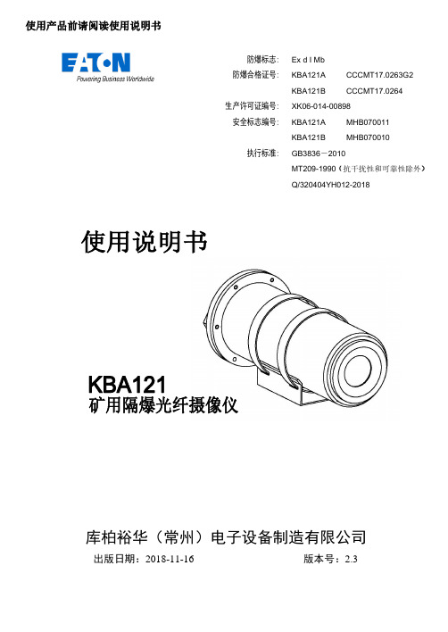
KBA121A/ KBA121B 矿用隔爆光纤摄像仪使用说明书Ver: 1.9库柏裕华(常州)电子设备制造有限公司出版日期:2018-11-16 版本号:2.3使用产品前请阅读使用说明书Ex d I Mb KBA121ACCCMT17.0263G2 KBA121BCCCMT17.0264XK06-014-00898KBA121AMHB070011 KBA121BMHB070010GB3836-2010MT209-1990(抗干扰性和可靠性除外) Q/320404YH012-2018防爆标志: 防爆合格证号: 生产许可证编号: 安全标志编号: 执行标准:KBA121A/ KBA121B矿用隔爆光纤摄像仪使用说明书Ver: 2.3安装、使用前请仔细阅读使用说明书。
1. 安装◼安装、使用前请仔细阅读使用说明书,遵守警告事项。
◼在对设备进行维护和检修之前,请务必切断电源。
◼避免在有油烟、灰尘严重、高温、结露的场所打开设备,否则可能导致图像清晰度下降。
◼请按本说明书要求正确安装电缆或光缆,否则有可能产生故障。
◼使用、维护过程中应注意隔爆面的保护,防止“失爆”!不得丢失引入装置中的密封圈!注意适当拧紧压紧螺母!◼避免金属碎屑或其它物质进入设备内部。
◼请勿对设备进行分解或改造。
2. 维护◼防爆电气的维修原则上,应由本公司进行维修,若使用单位自行维修时,建议应在征得本公司同意后,方可进行,维修方承担产品维修后的相关责任。
◼防爆电气设备的维修,应由掌握、熟悉防爆电气知识的专业人员进行检查与维修。
严禁带电开盖!◼在对设备进行维护和检修之前,请切断电源。
◼在对设备进行维护时,注意对隔爆面的保护。
◼维修单位应具备维修的装备和必要的检查和试验装置,并经检验合格后,方可投入使用。
3. 环保◼本公司所生产的各类产品,其中有可能包含对环境造成污染的零部件,如电路板、电子元器件、塑料制品、润滑油脂等,当设备维护或报废时,请注意对这些污染源进行收集、控制,不要随意丢弃,应当移交给相关环保部门进行处理,以免对环境造成不良影响。
网络摄像机设置说明书

网络摄像机设置说明书设置说明书注意:使用IP搜索工具局域网登录摄像机对其进行功能设置后,添加到电脑客户端或手机客户端内统一管理或访问。
1. 安装IP搜索器2. 局域网登录设备3. 选择语言和模式进入IE界面4. IE操作主界面使用说明5. 摄像机功能设置5.1 设备信息5.2 设备名称设备5.3 设备时钟设置5.4 地录像路径5.5设置报警服务:移动侦测报警5.6 邮件服务设置5.7 FTP服务设置5.8 基本网络配置5(9 无线局域网设置5.10 PTZ设置leading cadres to everyday things busy as an excuse, "urged not do" or "knock on the ring look, lack of work enthusiasm and forward-looking. The difficulties and problems of individual cadres indifferent masses as the buck passing, long, make some simple complex problems. Some cadres general talk about pay, do not take5.11设备用户设置(摄像机加密)5.12设备维护(恢复出厂设置/重启设备/系统升级) 5.13返回视频界面5.5.14 TF设置1. 安装IP搜索器直接在光盘中打开IP搜索工具,或拷贝到桌面打开。
2. 局域网登录设备当前网络中存在的设备,选中其中一台,双击进入。
问题1:点“刷新”仍然不显示IP地址检查方法:?确认设备已接通电源并网线一端接入摄像机,另一端接入路由器。
leading cadres to everyday things busy as an excuse, "urged not do" or "knock on the ring look, lack of work enthusiasm and forward-looking. The difficulties and problems of individual cadres indifferent masses as the buck passing, long, make some simple complex problems. Some cadres general talk about pay, do not take观察摄像机信号是否正常,网口灯一个常亮一个闪烁。
网络摄像机说明书中文版

目录第一章产品介绍 (1)第二章产品安装 (2)第三章搜索设备并登陆 (3)第四章视频属性设置 (4)第五章系统设置选项 (5)第六章报警设置 (6)第七章控制面板 (7)第八章注销 (8)第九章通过广域网访问网络摄像机 (9)第十章通过手机访问网络摄像机 (10)第一章产品介绍IPCAM 是一种通过网络传输动态视频的设备,它可以将本地的动态视频通过网络传输到世界各地有网络连接的地方,通过互联网,用户可以随时看到想监控的地方,拓展了人类的视野范围。
IPCAM 的视频传输基于TCP/IP协议. 内置Web服务器支持Inertnet Explore,用户可以通过Web页面管理和维护您的设备,实现远程配置,启动和升级固件。
您可以使用IPCAM监控家庭,办公室,工厂,连锁店,幼儿园等需要监控的场合,通过网络监控,可以对想监控的地方一览无余,在时间和空间上都大大方便了用户。
1.1系统配置需求:在电脑上观看网络摄像机的图像,您的机器需要的最低配置:1.Pentium III以上CPU,1GHz或更高主频;2.至少有256M内存;3.windows xp,2000以上操作系统,安装internet explorer 4.0以上浏览器,建议使用internet explorer 8.0观看。
1.2产品特征:安装简易:网络摄像机安装非常简单,不需要专业的布线,只需要电源和网络络连接,如果是采用WIFI无线连接,则只需要提供电源即可;适用范围:适用于家庭、办公室、企业、超市、学校以及其他需要监控的公共场所;多协议支持:内置嵌入式操作系统,支持TCP/IP 网络协议、SMTP (简单邮件发送协议),HTTP,UPNP等;配置简单——管理配置界面使用标准的Web浏览器,用户能够通过局域网或者因特网控制和管理网络摄像机;视频观看和录像:提供简洁的用户界面以观看实时图像,并可以录在你的电脑上,以备随时查阅。
报警监测:通过外部报警装置,把报警信息发送到到你想要发送的邮箱或者手机上,或者通过移动侦测来侦测用户选择的区域来进行布防,在有非法侵入时,也可以实现报警,并按照用户指定的邮箱发送信息和照片。
网络摄像头产品使用说明书
正常情况 光圈太暗
聚焦不正常 变焦
3.4 恢复出厂设置 由于某种原因需要恢复到出厂设置时,可以按以下步骤恢复摄像头的出厂设置。 u 先将摄像头上的电源插头拔下来 u 按下恢复出厂设置按键 u 同时将电源插头插入到摄像头上的电源插口 u 观察状态灯,当状态灯闪亮-〉亮灯时,说明摄像头已经恢复到出厂设置了
33 使用方法............................................................................................................ 8
3.1 摄像头正常工作.................................................................................................................8 3.2 观看图像 ............................................................................................................................8 3.3 调节镜头 ............................................................................................................................8 3.4 恢复出厂设置.....................................................................................................................9 3.5 USB 的使用........................................................................................................................9
网络高清摄像机安装使用手册(中文版)说明书
网络高清摄像机中文V1.1网络高清摄像机安装使用手册V1.1非常感谢您购买我公司的产品,如果您有什么疑问或需要请随时联系我们。
本手册为网络高清摄像机通用产品手册,支持功能由于型号不同而有所区别,请以实物为准。
本手册旨在供您作为操作和编程系统时的参考工具。
您可以在本手册中找到有关功能和命令的信息,以及详细的菜单树和快速操作指南。
在安装和使用系统之前,请充分了解本手册中的信息。
本手册可能包含技术上不准确的地方、或与产品功能及操作不相符的地方、或印刷错误。
我公司将根据产品功能的增强而更新本手册的内容,并将定期改进或更新本手册中描述的产品或程序。
更新的内容将会在新版本中加入,恕不另行通知。
在使用视频监控设备时请严格遵守当地的法律法规。
安全使用注意事项此内容的目的是确保用户正确使用本产品,以避免危险或财产损失。
在使用此产品之前,请认真阅读此说明手册并妥善保存以备日后参考。
如下所示,预防措施分为“警告”和“注意”两部分:警告:无视警告事项,可能会导致死亡或严重伤害。
警告在本产品安装使用中,必须严格遵守国家和使用地区的各项电气安全规程。
1.请使用正规厂家提供的电源适配器。
2.请不要将多个网络摄像机连接至同一电源(超过适配器负载量,可能会产生过多热量或导致火灾)。
3.在接线、拆装等操作时请一定要将智能球电源断开,切勿带电操作。
4.在墙壁或天花板上安装本产品时,请牢固地固定住网络摄像机。
5.如摄像机中出现冒烟现象,或产生恶臭,或发出杂音,请立即关掉电源并且将电源线拔掉,并同经销商或服务中心联系。
2 / 706.如果设备工作不正常,请联系购买设备的商店或最近的服务中心,不要以任何方式拆卸或修改设备。
(对未经认可的修改或维修所导致的问题,本公司不承担责任)。
注意1.请不要使物体摔落到设备上或大力震动设备,并使设备远离存在磁场干扰的地点。
避免将设备安装到表面震动或容易受到冲击的地方(忽视此项可能会损坏设备)。
2.请不要将摄像机瞄准强光物体,如太阳、白炽灯等,否则会造成摄像机的损坏。
网络摄像机安装使用说明书
网络摄像机安装使用说明书网络摄像机安装使用说明书Page 1 of 11目录第1章软件的安装............................................................................................................ (2)第2章网络摄像机使用说明............................................................................................................ ....................... 3 网络摄像机安装使用说明书Page 2 of 11第1章软件的安装运行“MultiViewer.exe”安装程序操作如下第一步选择语言中文、英文可选如图1-1所示图1-1 图1-2 第二步点击“下一步”出现如图1-2所示第三步选择安装目录如图1-3所示第四步继续选择“下一步”出现如图1-4、1-5所示图1-3 图1-4 图1-5 图1-6 第五步点击“安装”安装完成后将会出现如图1-6所示第六步点击“结束”安装完毕。
网络摄像机安装使用说明书Page 3 of 11 第2章Multiviewer流媒体多画面使用说明1 多画面分割是软件是在一台电脑上同时显示不同的多画面用来显示网络摄像机的图像用户根据网络摄像机的IP地址来设置不同和参数从而进行多画面的分割观看。
2 本地、远程分割器的配置第一步安装分割器软件直接将分割器软件放在桌面由用户自己来命名第二步双击分割器软件如图1-1所示图1-1 图1-2 第三步见红线处双击“Multiviewer”多画面分割器出现用户名、密码对话框其用户名是“admin”密码是“123456”点击“确定”如图1-2所示第四步点击“确定”出现如图1-3所示图1-3 图1-4 第五步选择“登陆系统”将会出现“用户名”“密码”用户名是“admin”密码是“123456”如图1-4所示图1-5 图1-6 网络摄像机安装使用说明书Page 4 of 11 第六步选择“用户管理”并双击将出现管理界面有“用户名”“用户组”“用户描述”见红线处admin/ 管理员/管理本地用户允许对系统进行配置在这三处点击“右键”将会出现“密码修改”、“用户名修改”、“更改用户组”可以对这三项来修改具有很高的安全性由用户根据需要来设定同时在空白处单击右键出现一个添加“用户”有“用户名”“密码”“密码确认”“帐号描述”也可由用户自己来根据需要来设定有“管理员”与“一般用户”可供选择用户可添加更多的用户来管理在“管理员和一般用户”中管理员可以控制所要监控的对象一般用户只能观看不能控制如图1-51-6所示第七步选择“视频配置”有“录像保存目录全局”指定一个保存位置它可以将整个图像保存下来“编号”是对所要配置网络摄像机IP地址顺序的排列有148路可填写由于电脑的CPU处理能力有限它只能同时播放16路“视频域名”是网络摄像机或网络球机的IP地址“视频端口”是网络摄像机或网络球机的视频端口“发布点名称”是文本文件填写live.asf“工作模式”有“视频开”“视频关”可供选择“WEB端口”“录像设置”“描述”详见后面详细说明如图1-7所示图1-7 图1-8 在“录像保存时间全局”时有“1天”“7天”“20天”“30天”由用户自己来选取在“循环播放间隔”有“不循环”“1分钟”“2分钟”“4分钟”“8分钟”可选根据用户自己的需要来设定。
矿用无线通信系统使用说明书
矿用无线通信系统使用说明书1、概述:1.1 用途KT201矿用无线通信系统做为新一代的矿井无线传输系统,采用WIFI与TCP/IP技术相结合,在煤矿井下实现了无线数据的高速传输,为煤矿提供了一个宽带无线传输平台。
该系统根据长春东煤机电研究所企业标准《Q/DMJD 30-2011 KT201矿用无线通信系统》研制、生产、配套和使用,以光纤网络为骨干(接入现有工业环网或独立组网),以无线网络延伸,在煤矿井下设立若干基站,通过无线通信手段,为实现人员的语音通信、人员管理、数字化视频监控及环境监测等提供了一个共用的平台;也为实现生产调度、应急救援与安全监控与督察提供了良好的应用基础。
系统可根据用户的实际需要灵活配置,它的推广应用将使煤矿通信走上新的台阶。
KT201矿用无线通信系统可根据煤矿企业的不同需求,配备不同的功能模块从而实现不同的功能。
通过无线通信系统,可以实现煤矿企业的通信一体化、管理一体化,数据交换的一体化、数据存储与使用的一体化。
避免了采用多个单独系统所带来的数据格式不一、交换效率低下、安全性差等诸多问题。
KT201矿用无线通信系统分地面和井下两部分。
地面部分由无线控制主机、语音服务器、KJJ127矿用隔爆兼本安型环网交换机以及专用监控软件组成,可配中英文打印机、远程终端、大屏幕投影仪等设备构成功能强大的信息处理中心。
井下部分主要由KJJ127矿用隔爆兼本安型环网交换机、KT201-F矿用隔爆兼本安型无线基站、DXB18矿用隔爆型电池箱、佩带在作业人员身上的KT201-S矿用本安型手机以及矿用通信光缆等构成通信网络。
1.2 系统型号含义如下图1所示:1.3使用环境条件1.3.1安装于地面机房、调度室的设备,环境条件须符合下列条件:1.3.1.1环境温度为15℃~30℃;1.3.1.2相对湿度为40%~70%(+25℃);1.3.1.3 大气压力为80kPa~106kPa;1.3.1.4清洁、无强磁场干扰,无腐蚀性气体和无爆炸性气体。
- 1、下载文档前请自行甄别文档内容的完整性,平台不提供额外的编辑、内容补充、找答案等附加服务。
- 2、"仅部分预览"的文档,不可在线预览部分如存在完整性等问题,可反馈申请退款(可完整预览的文档不适用该条件!)。
- 3、如文档侵犯您的权益,请联系客服反馈,我们会尽快为您处理(人工客服工作时间:9:00-18:30)。
使 用 说 明 书
KBA18W矿用本安型无线网络摄像仪
执行标准: Q/HK014-
MT209-1990(抗干扰与可靠性除外)
GB3836-
版 本 号 V1.0
出版日期 -9
济南华科电气设备有限公司
地址: 济南市高新区天辰大街1251号3号
楼201室
电话: 传真:邮编250100
KBA18W矿用本安型无线网络摄像仪
资料内容仅供您学习参考,如有不当之处,请联系改正或者删除。
一、 概述
1.1 主要用途和工作原理
KBA18W矿用本安型无线网络摄像仪(以下简称”摄像仪”) , 防爆标
志为Exib I Mb, 应用于煤矿有甲烷和煤尘爆炸的危险场所中。
该摄像仪允许安装在煤矿井下有甲烷和煤尘爆炸的危险气体环境中,
是新型的防爆监控设备, 它采用了先进的制造工艺, 凭借成熟的质量管
理体系作为保证, 使得产品的质量和性能在国内为同类行的产品处于领
先地位。KBA18W摄像仪具有体积小, 重量轻, 低照度, 高清晰度, 配置灵
活等特点。
1.2 规格型号及其含义
KB A 18 W
无线传输型
额定工作电压
摄像仪
矿用仪器仪表
1.3防爆型式和标志
1.3.1 防爆型式: 矿用本安型
1.3.2 防爆标志: Exib I Mb
1.4外形尺寸及重量
1.4.1外形尺寸: φ110mm×320mm 天线尺寸: 140mm×120mm×
40 mm
资料内容仅供您学习参考,如有不当之处,请联系改正或者删除。
1.4.2重 量: 约10kg
1.4.3尺寸图
1.5 环境要求
除有关标准另有规定外, 摄像仪在下列环境条件下应能正常工作
使用环境
环境温度: 0℃~+40℃;
相对湿度: 不大于95%( +25℃) ;
大气压力: 80kPa~106kPa;
机械环境: 无显著振动、 冲击和直接漏水、 淋水的场合; 可在含有甲
烷和煤尘爆炸性环境中使用, 但无破坏绝缘的腐蚀性气体的混合场合中
使用, 不可在强电磁场的环境中使用。
贮运环境
温 度: -40℃~+60℃
平均相对湿度: ≤90% ( +25℃)
机械环境: 振动加速度20m/s2, 冲击加速度300m/s
2
二、 主要性能
资料内容仅供您学习参考,如有不当之处,请联系改正或者删除。
2.1 供电
2.1.1摄像仪额定工作电压: 18 V (DC)
2.1.2摄像仪最大工作电流: 700 mA
2.2 摄像仪无线传输参数( 在200±50lux环境照度下)
a) 通讯协议: IEEE802.11 g
b) 工作信道: 1,6, 11信道
c) 工作频率: 2400MHz~2483MHz
d) 发射场强: -10dBm/m~-30dBm/m
e) 接收灵敏度: ≤-80dBm/m
f)
无线传输距离: 至KT158-F无线基站距离不小于150米。( 与基
站通讯范围内无遮挡物)
2.3天线参数
a) 天线型号: TDJ-2400BFA-Y
b) 外壳材质: 塑料ABS
c) 馈线: 不大于1.5m(使用煤矿用阻燃射频同轴电缆, 型号:
MSYV-50-3)
2.4图象参数( 在2lux环境照度下)
图象色彩: 黑白;
水平清晰度: 350TVL;
灰度等级: 7级。
2.5 功能
将视频图像信号采集、 压缩、 编码, 然后经过无线的方式传输到以太网
中。
资料内容仅供您学习参考,如有不当之处,请联系改正或者删除。
三、 安装使用说明
3.1 摄像仪安装
在安装前, 首先进行全面的检查, 查看经运输后是否有螺钉及零部件松
动, 脱落现象, 查看玻璃有无坏点, 查看紧定螺钉是否松动, 脱落, 查看摄
像机发射端是否完好, 确定设备完好方可安装。
A ) 将按装支架固定在岩壁( 或棚架) 上, 然后用螺钉将摄像机固定在
安装支架托板的相应位置。
B) 固定好天线, 使其信号最强。
C) 连接好接地线。
3.2 要求和注意事项
A 严格按照《煤矿安全规程》的规定进行安装和使用。
B 严禁井下带电开盖.
C 供电电源应符合本产品的要求。
D 检修时,不得随意更改产品元器件的参数、 规格、 型号。
四、 设备操作说明
1.
网络摄像机默认的IP地址为192.168.1.19, 可修改网络摄像机的IP地
址。并将你的计算机 IP地址改为与网络摄像机相同的网段里。具体步
骤是:
资料内容仅供您学习参考,如有不当之处,请联系改正或者删除。
参数设置----网络参数-----IP地址及端口更改即可。
2. 测试网络摄像机是否启动正常。具体的步骤是: 【WIN+R】快捷键调
出运行命令, 在命令行窗口内输入Ping 192.168.1.19,若不显示”Request
time out”, 则表明启动正常。
3. 当用IE浏览器首次访问网络摄像机时, 必须临时降低安全设置以便将
ActiveX 组件一次性地安装到网络中, 从浏览菜单上选择工具Internet
选项安全自定义级别ActiveX控件和插件, 设置安全级别为低并单
击重置。
4. 在IE浏览器地址栏里输入,出现如下图的登录页面:
仔细阅读网页页面提示, 若需要安装控件, 请单击”下载安装控件”按钮,
然后按照提示就能够顺利完成控件的安装。
输入用户名: 888888( 出厂默认, 管理员用户) 或1(普通用户);