语音捕获BR261-D
EUA2380 Ver1.0(1)
APPLICATIONS
Televisions USB Speaker Mini Speaker Consumer Audio Equipment
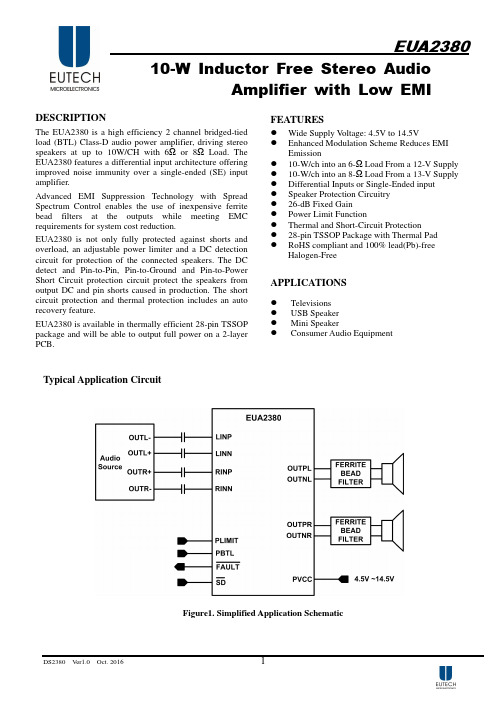
Typical Application Circuit
Figure1. Simplified Application Schematic
DS2380
Ver1.0
DS2380
Ver1.0
Oct. 2016
3
EUA2380
Absolute Maximum Ratings
▓ ▓
▓
▓
▓
▓
▓
▓
▓
▓
▓
▓
▓
▓
Supply Voltage, AVCC to GND, PVCC to GND ---------------------------------------------------- -0.3 V to 16V Input Voltage, SD , FAULT ,PBTL --------------------------------------------------------- -0.3 V to AVCC +0.3V Input Voltage, PLIMIT ---------------------------------------------------------------------- -0.3 V to GVDD +0.3V Input Voltage, RINN,RINP,LINN,LINP ------------------------------------------------------------- -0.3 V to 6.3V Thermal Resistance θJA (TSSOP-28) -------------------------------------------------------------------34°C /W Free-air Temperature Range, TA --------------------------------------------------------------------- -40°C to +85°C Junction Temperature Range, TJ -------------------------------------------------------------------- -40°C to +150°C Storage Temperature Rang, Tstg ------------------------------------------------------------------- -65°C to +150°C Lead Temperature -----------------------------------------------------------------------------------------260°C Load Resistance, RLOAD (BTL, PVCC>12V )---------------------------------------------------------4.8Ω Load Resistance, RLOAD (BTL, PVCC≤12V )---------------------------------------------------------3.2Ω Load Resistance, RLOAD (PBTL, PVCC>12V ) -------------------------------------------------------2.5Ω Load Resistance, RLOAD (PBTL, PVCC≤12V )--------------------------------------------------------2Ω ESD Susceptibility (HBM) ------------------------------------------------------------------------------2kV
SONY 高清晰度数字摄录一体机 HVR-S270C 操作指南

3M:\XL\XPCS A7.0\CS\3280852211_CX95000(Trados Project)_CS(FM7.1 600dpi)\3280852211_CX95000(Trados Project)_CS\01CS01REG.fm HVR-S270C 3-280-852-21(1)使用本摄像机•切勿握住摄像机的以下部位来拿起摄像机。
b 注意•本摄像机不防尘、防湿或防水。
请参阅“关于操作摄像机”(第102页)。
•请勿将电缆以错误的端子方向连接到摄像机。
将端子挤压到摄像机的插孔中可能会损坏端子或者导致摄像机故障。
关于菜单项、液晶屏、取景器和镜头•灰色显示的菜单项在当前录制或播放条件下不可用。
•液晶屏和取景器是采用极高精度技术制造而成的,因此可有效使用99.99%以上的像素。
但是,液晶屏和取景器上可能会持续出现一些很小的黑点和/或亮点(白、红、蓝或绿色)。
这些点是由制造过程产生的,属于正常现象,在任何情况下都不会影响录制。
关闭镜头盖或将摄像机放入袋内。
关于录制•开始录制之前,先测试录制功能,以确保录制的图像和声音没有任何问题。
•即使由于摄像机、储存媒质等出现故障而无法录制或播放,也不对录制的内容提供赔偿。
•电视机彩色制式视国家/地区而有所不同。
要在电视机上观看录制的内容,您需要基于PAL 制式的电视机。
•电视节目、电影、录像带和其它材料可能具有版权。
如果未经授权对这些材料进行录制,可能会违反版权法。
固定器内存记录器续,01CS00BOOK.book Page 3 Tuesday, December 4, 2007 5:09 PM4M:\XL\XPCS A7.0\CS\3280852211_CX95000(Trados Project)_CS(FM7.1 600dpi)\3280852211_CX95000(Trados Project)_CS\01CS01REG.fm HVR-S270C 3-280-852-21(1)关于在其它设备上播放HDV 录像带在不兼容 HDV 格式的设备中无法播放以HDV 格式录制的录像带。
音频抄录设备与访问网关产品配置指南说明书

Configuration Guide AudioCodes 420HD IP Phone with Genesys® SIP ServerDocument #: LTRT-21941Configuration Guide ContentsTable of Contents1Introduction (7)1.1Distributing Calls Automatically to Available Agents (7)1.2Ensuring SIP Business Continuity for Agents (7)2Provisioning IP Phones Automatically (9)2.1Using DHCP to Auto Provision Phones (9)2.2Verifying Firmware Version (9)2.3Accessing a Phone's Web Interface (9)2.4Enabling the ACD Feature (10)2.5Configuring Dual Registration for Genesys Business Continuity (11)2.6Disabling the Web Interface (15)2.7Forcing a Reboot on Provisioning (15)2.8Provisioning using TFTP / FTP / HTTP / HTTPS in DHCP Options 66/67 (15)2.9Provisioning using DHCP Option 43 (15)2.10Enabling Agents to Sign in with Phone Numbers (16)2.11Locking Agents Phones Alphabetical Keys (16)2.12Provisioning using DHCP Option 12 (16)2.13Playing a Beep on an Incoming Call (17)2.14Enabling Proactive Mute (17)2.15Limiting the Length of Time 'Logged out' is Displayed (17)3Using IP Phones in Genesys Contact Centers (19)3.1Logging in (19)3.2Changing your Status from 'Ready' to 'Not Ready' (19)3.3Restoring your Status from 'Not Ready' to 'Ready' (20)3.4Logging out (20)3.5Configuring Automatic Forwarding (20)3.6Configuring Do Not Disturb (DnD) (21)3.7Configuring 3rd Party Call Control (3PCC) (21)Genesys ServerList of FiguresFigure 2-1: Web Interface - ACD (10)Figure 2-2: Web Interface - Signaling Protocol – SIP Proxy and Registrar (11)Figure 2-3: Web Interface - Signaling Protocol – SIP Proxy and Registrar – Secondary Proxy (12)List of TablesTable 2-1: ACD Parameters (10)Table 2-2: SIP Proxy and Registrar Parameters (12)Table 2-3: Disabling the Web Interface (15)Table 2-4: Forcing a Reboot on Provisioning (15)Table 2-5: Enabling Agents to Sign in with Phone Numbers (16)Table 2-6: Locking Agents Phones Alphabetical Keys (16)Table 2-7: Playing a Beep on an Incoming Call (17)Table 2-8: Enabling Proactive Mute (17)Table 3-1: 3PCC Parameters (21)Configuration Guide NoticesTrademarksAudioCodes, AC, AudioCoded, Ardito, CTI2, CTI², CTI Squared, HD VoIP, HD VoIPSounds Better, InTouch, IPmedia, Mediant, MediaPack, NetCoder, Netrake, Nuera, OpenSolutions Network, OSN, Stretto, TrunkPack, VMAS, VoicePacketizer, VoIPerfect,VoIPerfectHD, What's Inside Matters, Your Gateway To VoIP and 3GX are trademarks orregistered trademarks of AudioCodes Limited. All other products or trademarks areproperty of their respective owners.WEEE EU DirectivePursuant to the WEEE EU Directive, electronic and electrical waste must not be disposedof with unsorted waste. Please contact your local recycling authority for disposal of thisproduct.Customer SupportCustomer technical support and service are generally provided by AudioCodes'Distributors, Partners, and Resellers from whom the product was purchased. For technicalsupport for products purchased directly from AudioCodes, or for customers subscribed toAudioCodes Customer Technical Support (ACTS), contact **********************.Abbreviations and ConventionsEach abbreviation, unless widely used, is spelled out in full when first used. Documentation FeedbackAudioCodes continually strives to produce high quality documentation. If you have anycomments (suggestions or errors) regarding this document, please fill out theDocumentation Feedback form on our Web site at /downloads.Genesys Server Related DocumentationConfiguration Guide 1. Introduction1 IntroductionThis guide shows system administrators how to configure AudioCodes' 420HD IP Phone tooperate with Genesys' SIP Server in a Genesys contact center.The guide also shows contact center agents how to use their IP phone's ACD (AutomaticCall Distribution) feature.In contact centers, ACD is a key feature of CTI (Computer Telephony Integration). Thefeature automatically distributes incoming calls to a specific group of terminals that contactcenter agents use. Most ACD functionality is the SIP Server's responsibility, but the IPphones must publish presence status (LOGIN / LOGOUT / AVAILABLE / UNAVAILABLE)for the SIP Server to make call distribution decisions.1.1 Distributing Calls Automatically to Available AgentsAutomatic Call Distribution (ACD) systems allow companies that handle a large number ofincoming phone calls to direct the callers to a company employee who is able to talk at theearliest opportunity.The ACD feature is typically implemented in contact centers encountering large numbers ofincoming customer calls that must be distributed to available agents to provide immediatesupport to callers. The feature automatically directs incoming calls to agents working in thecontact center whose presence status is 'Available' rather than unavailable. The feature'smain benefit is therefore to reduce the time customers are kept waiting for service andthereby improve customer service.AudioCodes' IP phones seamlessly interwork with Genesys' SIP Server to support the ACDfeature. Once an agent signs in on their phone to ACD, their status is set to 'Available' andsynchronized with Genesys' Server. Incoming calls are directed to an agent whenever theirstatus becomes 'Available'.1.2 Ensuring SIP Business Continuity for AgentsAudioCodes' 420HD IP phone supports dual registration for integrating into Genesys' SIPBusiness Continuity architecture.SIP Business Continuity provides the ability for a group of agents to continue offeringcritical business functions to customers in the event of a loss of all Genesys componentsrunning at a particular site.The SIP Business Continuity architecture uses a synchronized, two-site deployment, whereGenesys switch and server components are mirrored at each site in an active-activeconfiguration, so that any agent can log in to either switch, at any time.In a standalone SIP Server configuration with Business Continuity mode activated,AudioCodes 420HD IP phone will register on two sites simultaneously (i.e., register on bothpeer SIP Servers at the same time).Genesys Server Reader's NotesConfiguration Guide 2. Provisioning IP Phones Automatically2 Provisioning IP Phones AutomaticallyThis section shows system administrators how to quickly set up AudioCodes' IP phones tooperate with a Genesys SIP Server in a Genesys contact center.2.1 Using DHCP to Auto Provision PhonesAfter connecting the LAN ports of your phones to the IP network and then connecting thephones to the power supply, the phones will by default send a request to the Genesyscontact center's network server which will then automatically allocate an IP address andsend configuration information to each phone.Make sure that the DHCP (Dynamic Host Configuration Protocol) options in your contactcenter's DHCP server are correctly configured.For detailed information on how to set up the DHCP server, see the Administrator's Manualor 400HD Series IP Phone Deployment Guide.2.2 Verifying Firmware VersionAfter automatic provisioning, make sure the phone's firmware version is correct.To verify firmware version:⏹Navigate to the Firmware Status screen in the phone's LCD (MENU key > Status >Firmware Status):2.3 Accessing a Phone's Web InterfaceUse a standard Web browser such as Microsoft® Internet Explorer® to access any phone'sWeb interface. Use the phone's IP address as the URL.To obtain the phone's IP address:⏹Access the Network Status screen in the phone's LCD (MENU key > Status >Network Status) and navigate down to IP Address:To access the phone's Web interface:1. Open the Web browser and in the URL address field enter the phone's IP address (forexample, http://10.22.13.118 or https://10.22.13.118):The Web login window opens.Genesys Server2. Alternatively, if your DHCP and DNS servers are synchronized, you can access thephone Web browser using the following method:http://<Phone Model>-<MAC Address>.<Domain Name>E.g. 3.Enter the User Name and Password, and then click OK . 2.4 Enabling the ACD FeatureThis section shows how to enable the ACD (Automatic Call Distribution) feature on the phone using either the Web interface or the Configuration File. The feature distributes incoming calls to agents' phones on the basis of agent availability and unavailability. To configure the ACD server using the Web interface:1. In the Web interface, access the ACD page (Configuration tab > AdvancedApplications > ACD ):Figure 2-1: Web Interface - ACD2. Configure the parameters using Table 2-1 below as reference.To configure the ACD server using the Configuration File:Define a path and configure the parameters using the table below as reference.Table 2-1: ACD ParametersConfiguration Guide 2. Provisioning IP Phones Automatically2.5 Configuring Dual Registration for Genesys BusinessContinuityThis section shows how to configure dual registration for Genesys SIP Business Continuity,using the Web interface or Configuration File.To configure using the Web Interface:1. In the Web interface, access the SIP Proxy and Registrar section in the SignalingProtocol screen (Configuration menu > Voice Over IP > Signaling Protocol): Figure 2-2: Web Interface - Signaling Protocol – SIP Proxy and RegistrarGenesys Server Figure 2-3: Web Interface - Signaling Protocol – SIP Proxy and Registrar – Secondary Proxy2. Configure the parameters using table below as reference.To configure using Configuration File:Use the table below as reference.Table 2-2: SIP Proxy and Registrar ParametersConfiguration Guide 2. Provisioning IP Phones AutomaticallyGenesys ServerConfiguration Guide 2. Provisioning IP Phones Automatically2.6 Disabling the Web InterfaceThis feature lets the call center's network administrator block Web interface access toagents employed in the call center.To disable access using Configuration File:∙Use the table below as reference.Table 2-3: Disabling the Web Interface2.7 Forcing a Reboot on ProvisioningThis feature lets the call center's network administrator configure a forced reboot onagents' phones after provisioning.To force a reboot on provisioning using Configuration File:∙Use the table below as reference.Table 2-4: Forcing a Reboot on Provisioning2.8 Provisioning using TFTP / FTP / HTTP / HTTPS inDHCP Options 66/67This feature lets network administrators enable phones to be automatically provisionedwhen the phones are plugged in, using TFTP / FTP / HTTP / HTTPS in DHCP Options66/67.2.9 Provisioning using DHCP Option 43This feature lets network administrators enable phones to be automatically provisionedwhen the phones are plugged in, using DHCP Option 43.Genesys Server2.10 Enabling Agents to Sign in with Phone NumbersThis feature lets the call center administrator power up all phones without setting a validSIP account. When an agent then wants to use their phone, they register to the networkwith their phone number.To enable the feature using Configuration File:∙Use the table below as reference.Table 2-5: Enabling Agents to Sign in with Phone Numbers2.11 Locking Agents Phones Alphabetical KeysThis feature lets call center network administrators lock agents' phones' alphabetical (non-numerical) keys so that only numerical keys are available to them. This feature providescall centers the option to limit agents to work-specific tasks. The feature reduces privateactivity on the part of agents. Agents cannot, for example, add contacts to a personaldirectory.When this feature is enabled, agents can only use numbers. Only two menus are availablein agents phones LCDs:⏹Status⏹AdministrationTo lock alphabetical keys using Configuration File:∙Use the table below as reference.Table 2-6: Locking Agents Phones Alphabetical Keys2.12 Provisioning using DHCP Option 12This feature lets call center network administrators enable automatic provisioning usingDHCP Option 12. The hostname is replaced by the agent's phone number after SIPregistration.Configuration Guide 2. Provisioning IP Phones Automatically2.13 Playing a Beep on an Incoming CallThis feature lets call center network administrators configure a beep to be played when acall comes in if auto-answer is configured. The beep is played on both speaker andheadset. Agents will know from the beep that they have an incoming call to attend to.To configure playing a beep using Configuration File:∙Use the table below as reference.Table 2-7: Playing a Beep on an Incoming Call2.14 Enabling Proactive MuteThis feature lets call center network administrators enable a proactive mute when callscome in so that when they come in, callers cannot hear the agents until the agents unmuteby pressing the Mute button. The feature can protect call centers from agent conduct thatmight be offensive to callers. Agents may for example pass an offensive remark to oneanother about a caller whose call is coming in, without realizing the caller can hear.To enable proactive mute using Configuration File:∙Use the table below as reference.Table 2-8: Enabling Proactive Mute2.15 Limiting the Length of Time 'Logged out' isDisplayedThis feature lets call center network administrators limit the length of time the 'Logged out'message is displayed after agents log out. When agents log out, the 'Logged out' messagewill only be displayed in the phone's idle screen for the length of time (in seconds)configured by the call center network administrator, following which it will disappear.Genesys Server Reader's NotesConfiguration Guide 3. Using IP Phones in Genesys Contact Centers 3 Using IP Phones in Genesys ContactCentersThis section shows how to use AudioCodes IP phones in Genesys contact centers.3.1 Logging inThis section shows you how to log in to the phone. Log in immediately after starting a shift.To log in to the phone:1. When the phone's LCD is in idle mode (Logged Out), press the Login softkey; the LogIn screen is displayed:2. Enter your Username. Obtain it from your system administrator. Press the A/a/1softkey successively to navigate to and select the alphanumerical mode you require(abc, ABC, or Abc).3. Scroll down and enter your Password.4. Press the Login softkey; the Ready idle screen is displayed.You're now available to take incoming calls. Incoming calls from now on will bedirected to your p hone.3.2 Changing your Status from 'Ready' to 'Not Ready'In the course of a shift, you may need to leave your desk for a break or to attend to otherissues. Before leaving your desk, change your status to 'Not Ready' (unavailable) so thatcalls coming in to the contact center will not be sent to you.To change your status to 'Not Ready':1. In the idle screen, press the Not Ready softkey; the Ready indication changes to NotReady:Genesys Server3.3 Restoring your Status from 'Not Ready' to 'Ready'When you return to your desk after taking a break or after attending to an external issue,it's important to restore your status to 'Ready' and resume work.To restore your status to 'Ready':⏹In the idle screen, press the Ready softkey; the Not Ready indication changes toReady.3.4 Logging outAt the end of your shift, log out of the phone.To log out of the phone:⏹In the idle screen, press the Logout softkey; the Logged Out indication is displayed:3.5 Configuring Automatic ForwardingWhen you leave your workstation you can configure the phone so that any incoming callswill be forwarded.To configure automatic forwarding:1. In the idle screen, press the softkey; the Command Menu opens.2. Select the Fwd option; the Automatic Forward screen opens.3. Select the Always option or scroll down and select the Busy or No Reply option.4. Enter the Number to Forward to, or scroll down and select Select from Directory inwhich you can choose a contact number to forward calls to.5. In the idle screen to which you're returned, view the foward indication:Configuration Guide 3. Using IP Phones in Genesys Contact Centers 420HD IP Phone 21 April 20143.6 Configuring Do Not Disturb (DnD)You can configure the phone so that no incoming calls will disturb you.To configure DnD:1.In the idle screen, press the softkey; the Command Menu opens.2. Scroll down and select the DnD option:3. In the idle screen to which you're returned, view the DnD indication:3.7 Configuring 3rd Party Call Control (3PCC)The 3PCC feature lets users control phones remotely from computer applications.3PCC always supports the following functions:⏹MakeCall (call initiation/setup) ⏹Release ⏹Hold ⏹Retrieve ⏹Transfer ⏹Consult ⏹ Conference To configure 3PCC using Configuration File:Use the table below as reference.Table 3-1: 3PCC ParametersConfiguration Guide AudioCodes 420HD IP Phone with Genesys SIP ServerDocument #: LTRT-21941。
电子元器件型对应表

电子元器件型号对应表741 运算放大器2063A JRC杜比降噪20730 双功放24C01AIPB21 存储器27256 256K-EPROM27512 512K-EPROM2SK212 显示屏照明3132V 32V三端稳压3415D 双运放3782M 音频功放4013 双D触发器4017 十进制计数器/脉冲分配器4021 游戏机手柄4046 锁相环电路4067 16通道模拟多路开关4069 游戏机手柄4093 四2输入施密特触发器409841256 动态存储器52432-01 可编程延时电路56A245 开关电源5G0401 声控IC5G673 八位触摸互锁开关5G673 触摸调光5G673 电子开关6116 静态RAM6164 静态RAM65840 单片数码卡拉OK变调处理器7107 数字万用表A/D转换器74123 单稳多谐振荡器74164 移位寄存器7474 双D触发器7493 16分频计数器74HC04 六反相器74HC157 微机接口74HC405374HCU04 六反相器74LS00 与门74LS00 4*2与非门74LS00 四2与非门74LS00 与门74LS04 6*1非门74LS08 4*2与门74LS11 三与门74LS123 双单稳多谐振荡器74LS123 双单稳多谐振荡器74LS138 三~二译码器74LS142 十进制计数器/脉冲分配器74LS154 4-16线译码器74LS157 四与或门74LS161 四2计数器74LS161 十六进制同步计数器74LS161 四~二计数器74LS164 数码管驱动74LS18 射频调制器74LS193 加/减计数器74LS193 四2进制计数器74LS194 双向移位寄存器74LS27 4*2或非门74LS32 四或门74LS32 4*2或门74LS374 八位D触发器74LS374 三态同相八D触发器74LS37774LS48 7位LED驱动74LS73 双J-K触发器74LS74 双D触发器74LS85 四位比较器74LS90 计数器75140 线路接收器75141 线路接收器75142A 线路接收器75143A 线路接收器7555 时钟发生器79MG 四端负稳压器8051 空调单片机8338 六反相器A1011 降噪ACVP2205-26 梳状滤波视频处理AD536 专用运放AD558 双极型8位D-A(含基准电压)变换器AD558 双极型8位D-A(含基准电压)变换器AD574A 12比特A/D变换器AD650AD670 8比特A/D变换器(单电源)1995s-2、15 AD7523 D-A变换器1994x-125AD7524 D-A变换器1994x-126AD7533 模数转换器1994x-141AD7533 模数转换器1995s-184ADC0804 8比特A/D变换器1995s-2、20 ADC0809 8CH8比特A/D 1995s-2、23ADC0833 A/D变换4路转换器1995s-2 ADC80 12比特A/D变换器1995s-2、8 ADC84/85 高速12比特A/D变换器1995s-2 AG101 手掌游戏机1993x-155AM6081 双极型8位D-A变换器1994x-127 AMP1200 音频功放皇后1993s-104AN115 立体声解码1991-135AN2510S 摄象机寻象器1994x-109AN2661NK 影碟机视频1995s-45AN2662K 时基校正(模拟)1995s-45AN2664FBP 影碟机视频1995s-45AN2664NK 影碟机视频1995s-45AN2870 影碟机伺服1995s-45AN3100N 射频调制器1991-55AN362 立体声解码1991-135AN363N 立体声解码1991-135AN3890FBS 影碟机主轴电机驱动1995s-45AN3891FBP 影碟机主轴电机驱动1995s-45 AN5026K 红外接收1993x-106AN51354 中放/音频/视频解调1994s-255 AN5138K 图象通道1994-308AN5265 音频功放1994s-298AN5342K 亮度锐度加强电路1994s-243 AN5344FBP CFU地1995s-274AN5352 模拟开关1994-245AN5515 彩电场输出1995s-34AN5515 场输出1994-73AN5521 场输出电路1991-203AN5521 场输出1994-73AN5521 场输出1994-240AN5521 场扫描1994-308AN5600K 图象处理1994-308AN5612 色差解调1994s-245AN5652 伴音中放1994-308AN5862K PIP切换输出1994s-245AN6551 双运放1991-54AN6612 电机稳速1992-63AN6612S 杜比降噪1995s-43AN6650 电机稳速1991-183AN6650 电机稳速1992-7AN6650 电机稳速1992-83AN6650 电机稳速1992-127AN6650 电机稳速1993s-165 AN6913L 双运放1995s-85AN7106K 单片放音机1992-63 AN7108 单片放音机1992-7AN7108 单片放音机1992-127 AN7108 单片放音机1992-136 AN7108 单片放音机1993s-165 AN7110 音频功放1994x-107 AN7112E 音频功放1994s-39 AN7158N 音频功放1991-3AN7158N 音频功放1991-203 AN7168 双音频功放1991-195 AN7178 音频功放1994x-107 AN7188NK 双音频功放1992-14 AN7311 双前置放大1991-195 AN7315 双前置放大1992-99 AN7410 立体声解码1991-135 AN74LS293 1994x-93AN7812 三端稳压器1994s-299AN78N05 三端稳压器1994s-298AP500/A DC功放驱动1995s-60AP500/A 双声道DC功放驱动1995s-156 AT24C01 存储器1994x-46ATC105 充电控制1993x-191AX5212D 微机鼠标编码1994s-183BA1035B 高速运放1994x-94BA1106F 放音前置放大及功放1995s-43 BA1310 立体声解码1991-135BA1320 立体声解码1991-135BA1330 立体声解码1991-135BA1335 立体声解码1991-135BA1404 调频发射1994x-183BA3015 电风扇电脑1994s-162BA3105 电风扇电脑1994x-58BA3212N 录放前置1994-180BA328 双前置放大1991-43BA328 低噪前置1992-58BA328 双声道前置放大1995s-189BA3506 音频功放1991-139BA3822LS 5段均衡1994-180BA508 遥控电路1995s-171BA5102 音频前置1993x-108BA5102 遥控电风扇编码1995s-119BA5104 电风扇遥控1995s-183BA527 音频功放1991-168BA5302 红外接收头1995s-183BA5406 双功放1992-47BA6124 电平指示1991-31BA6209 录象机加载1991-11BA6209 主导电机驱动1994-192BA6219B 加载电机驱动1994-120BA6227 电机稳速1991-139BA6303 磁鼓控速1992-139BA6439P 主导电机驱动1994-120BA728 双运放1992-91BA7751LS 录象机音频处理1993s-84 BA8105 遥控电风扇电路1995s-119BA8206A4 电风扇控制1995s-183BAS3108T FM发射1992-94BGJ3302 四运放电压比较器1994-25 BH-SK-I 声控IC 1994s-175BH-SK-V 声控IC 1994x-74BISS0001 红外传感信号处理1995s-182BL3102 时钟频率脉冲1994s-255BL3207 BBD延时1994s-255BL50462AP 遥控编码与发射1995s-299 BM5060 彩电CPU 1994-308BM5067 彩电CPU 1995s-212BM5069 彩电CPU 1995s-212BTS114 感温高速开关管1992-34BTS115 感温高速开关管1992-34BTS130 感温高速开关管1992-34BTS131 感温高速开关管1992-34BTS240 感温高速开关管1992-34BTS412 电源开关模块1992-112C036 4*2与非门1993s-93C043 双D触发器1993s-101C066C 4*2与非门1993x-147C1225H 音响驱动1992-198C1470 电机稳速1992-99C1490HA 红外接收1991-110C1676 超高频放大1995s-199C1891A 环绕声处理器1992-24C7642 单片收音机1991-95CA3069 运放1994x-184CA3160 1994x-188CA3193 音频运放1994x-36CA3524 脉冲调制1992-14CC14433 三位半A/D转换1991-46CC14433 三位半A/D转换1991-174CC4093 含施密特触发器的四2输入与非门1994s-44 CC4511 七段译码器1991-46CCU3000-17 从属微处理器1995s-299CCU3002-FDTV-11 彩电CPU 1995s-299CD1403 单运放1991-2CD4001 4*2或非门1993s-69CD4001 4*2或非门1994x-2CD4011 4*2与非门1993s-53CD4011 4*2与非门1993x-150CD4011 四2输入与非门1994s-80CD4013 双D触发器1991-2CD4013 双D触发器1993s-101CD4013 双D触发器1993x-6CD4013 双D触发器1994s-82CD4013 双D触发器1994x-22、54CD4017 十进制计数/分配1991-110CD4017 十进制计数/分配1993s-142CD4017 十进制计数译码器1994s-82CD4017 十进制计数器/脉冲分配器1994s-34 CD4017 十进制计数器/脉冲分配器1994x-2 CD40174 六D触发器1992-130CD4017B 十进制计数/分配1993x-173CD4017B 十进制计数器1995s-184CD40193B 双向可预置可逆计数器1994x-84 CD4020 14级二进制计数器1994s-80CD4024 七位二进制串行计数器1994s-80 CD4028 二~十进制译码器1992-98CD4035 移位寄存器1994s-72CD4040 十二进制二进制计数器1992-22 CD4040 十二进制二进制计数器1993s-207 CD4040 12级二进制计数器1993x-125CD4040 12级二进制计数器1994s-80CD4046 锁相环电路1994x-188CD4046 锁相环电路1995s-181CD4051 模拟开关1992-130CD4051 模拟多路转换器1995s-2、35CD4052 四选一模拟开关1992-82CD4053 3*2模拟开关1992-62、207CD4053 3*2模拟开关1994x-54CD4053 3*2模拟开关1994x-126CD4053B TV/AV切换1994-219CD4053B 双向模拟开关1994-247CD4060 分频计数1993s-12CD4060 十四位计数器/分配器/振荡器1994s-30、40 CD4066 4*2模拟开关1992-112CD4066 4*2模拟开关1993s-91CD4066BE 四路模拟开关1994-269CD4067 模拟多路转换器1992-162CD4067 模拟多路转换器1995s-2CD4069 6*1非门1991-166CD4069 6*1非门1993s-45CD4069 6*1非门1993x-150CD4069 六非门1994s-4、82CD4071 4*2或门1994s-30CD4072 2-4输入或门1992-130CD4075 三或门1991-170CD4078 多输入或门1991-170CD4093 四与非门施密特触发器1994x-42CD4099 8路可寻址锁存器1991-170CD4510 二~十加减计数器1992-98CD4511 LED显示驱动1991-2CD4511 译码驱动1993x-159CD4511 译码显示1994s-30CD4514 4-10线译码器1993x-158CD4518 双二~十进制计数器1993x-125 CD4518 计数器1994s-30CD4541B 双D触发器1995s-79CD4553 三位BCD码计数器1993s-47 CD74206 音频功放1994x-107CD9020-002 字符产生器1994s-255CD9135 六路互复位触摸开关1994x-188 CE550 电风扇控制1994s-170CH1058 音乐片1991-192CH208 译码输出1991-174CH220 电子密码锁1994x-26CIC7642 调幅收音1994s-55CIC9140 电话按键码1993s-107CNX82A2 稳压反馈光电耦合器1995s-299 CP4027 双J-K触发器1993s-109CS839 霍尔开关1994s-34CS8704 电话振铃1994-46CSC5089 单片电话机1994-77CTC9140 电话脉冲拨号1994-46CU001 多功能遥控1991-56CU47C433AN-002 彩电CPU 1994s-255 CW-18 呼救语音1993x-133CW8403 音乐IC 1993s-125CW9300 音乐IC 1993s-101CW9300 音乐IC 1993x-198CX20029 单片收音机1992-111CX20106 红外接收1993s-126CX20106 红外接收1994-230CX20106A 红外预放器1991-30CX20106A 红外接收1994x-22CX20111 调频调幅中放1992-127CX20112 电视立体声/多语种解码1994x-4 CX20188 杜比B/C降噪1992-174CX522-054 彩电CPU 1994s-302CX7959 存储器1994s-307CXA1019 单片收音机1991-114CXA1019 单片调频收音1991-152CXA1019 调频静噪1995s-52CXA1019M 单片收音机1994-74CXA1019P 单片调频收音1993x-85CXA1034P 单片放音机1992-83CXA1100 杜比降噪1991-106CXA1101 杜比降噪1991-106CXA1101 杜比降噪1992-108CXA1102 杜比降噪1991-106CXA1145P 游戏机色处理1991-131CXA1145P PAL编码1993x-78CXA1191M 调幅调频电视单片收音1993x-158 CXA1191M 单片收音机1994s-198CXA1191M 单片调频调幅收音1994x-63CXA1191P 收音专用1994-11CXA1238 单片收音机1991-140CXA1238M 调频收音1994s-130CXA1238M 调频收音1994s-156CXA1250 场频驱动1993x-103CXA1262N 单片放音机1993x-99CXA1315M 彩电副总线1995s-272CXA1642 消歌声1993s-64CXA1642 消声(卡拉OK)1995s-36CXA1642 消歌声1995s-204CXA1644P 卡拉数字延时1993x-72CXA1735S 音频处理器1995s-272CXA8008P 单片放音机1991-75CXA8008P 单片收音机1992-163CXD1254AQ 摄象机同步1993x-103CXD1310BLA 视频处理器1993x-103CXK1001P 存储器1994-307CXP80420-139S 彩电CPU 1994-334D1130 AM/FM收音1992-43D2024 音频功放1991-48D2283 音频低放1994s-135D2283 音频功放1994x-47D2822 助听器专用1991-167D414 单片收音机1991-167D7176AP 中放及伴音鉴频1994-19D7240AP 音频功放1991-3D75028CW 空调器CPU 1995s-194D7796 音频均衡1991-32DAC08 双极型8位D-A变换器1994x-129DAC08 双极型8位D-A变换器1994x-135DAC90 双极型8位D-A(含基准电压)变换器1994x-126 DBL2004 彩电场输出1995s-34DCM0016 系列高速带掉电保护RAM 1995s-174DCM0064 系列高速带掉电保护RAM 1995s-174DCM0256 系列高速带掉电保护RAM 1995s-174DCM8128 系列高速带掉电保护RAM 1995s-174 DJ2001 洗衣机电脑1991-159DN888 数字延迟1993x-110DPU-2553-25 偏转处理器1995s-299DRAM4164 数据存储1993s-80DS8629N 100分频器1992-22DTI-2260 数字瞬态改善处理器1995s-299EA1062 语音电路1994-138EK001 混频厚膜1994s-255ELM742A 低压低功耗电压比较器1995s-118 ET91210 电话程控1991-58F1212 程序快门1992-71GL7488P 录象机伺服系统1994-210GP605 开关电源PWM脉宽调制1995s-126 GS8200 录象机系统控制1994-210GSE-3568 多音声效片1994s-128GY65839 单片卡拉OK专用1994s-172GY9308 DDC数码延迟1993x-120GY9403 数码卡拉OK延迟1994x-52H9081 四声5闪光片1994x-167HA11227 立体声解码1991-135HA112A 音乐门铃1991-156HA11414 行场扫描1993s-28HA11489 亮度/彩色矩阵1991-203HA11489 视频处理1994x-19HA11509N 亮/色/行场扫描1991-43HA1166Z 黑白机行场扫描1994-82HA12017 放音均衡1991-8HA12058 杜比降噪1993x-160HA12102 双前置放大1991-43HA13001 音频功放1993s-75HA13119 音频功放1994x-99HA1392 音频功放1992-188HA1397 音频功放1991-176HA3302 四运放电压比较器1994-25HA51338SP 亮/色/行场扫描1991-43HA51338SP 彩电行场扫描/色度/亮度1995s-163 HCF40015 红外接收前置放大1994s-118HD14053B 电视遥控发射1993x-164HD401304 彩电CPU 1995s-174HD401314 彩电CPU 1995s-174HD44007A 彩色同步1991-14HEF4017 2-10进制计数器/脉冲分配器1994x-22 HEF4053BP 3*2模拟开关1994s-7HEF4066B 四路模拟开关1994-269HEF4503 3*2模拟开关1992-207HF-268/288 保密语音模块1995s-94HFC3030 彩灯闪光片1994x-71HFC3040 多发光二极管控制1991-64HFC3040 彩灯六路闪光芯片1994s-50HFC5203A 语音1994x-90HFC5219 “有电危险、请勿靠近”语音块1995s-95 HIC101 放象机电源厚膜块1995s-85HM50256 动态存储器1995s-159HM50464 动态存储器1995s-159HM511000 动态存储器1995s-159HM6117 游戏存储1993s-11HM6232 电源厚膜1993x-35HM6401 电源/场输出厚膜1991-115HM7101 电源厚膜1993x-35HM7942 电源厚膜1993x-35HM8951 电源厚膜1993s-35HM8951A 电源厚膜1995s-99HM8951B 电源厚膜1993x-195HM8951B 电源厚膜1994-65HM9007 电子镇流器1991-82HM9007 电子镇流器1993s-146HM9102 电源厚膜1992-103HM9102 电源厚膜1993x-35HM9102 开关电源取样1994-141HM9102D 电话按键码1993s-107HM911L 热释电红外线探测1994x-194 HM9201 电源厚膜1993x-35HM9205 稳压电源取样1994-332HM9207 电源厚膜1993s-3HM9207 电源厚膜1994-65HM9207B 电子镇流器1994s-6HM-JL1 音频模块1993s-160HN6401 电源厚膜1993x-35HPC177C 四运放电压比较器1994-25 HPC339C 四运放电压比较器1994-25 HT12C 遥控发射1994x-110HT2880 八音音乐片1994s-32HT6337A 风扇遥控接收1994x-110 HT7713 声控闪光片1994x-10HT7713 触摸调光1994x-63HT82D 双音音乐门铃1994s-32HY12503 可程式化语音模块1995s-94HY-20A 语音录放1994s-78HY42503 可程式化语音模块1995s-94HY-88A 动物叫声效片1993x-182HY8-S 三端音乐片1991-172IC1818P 单片游戏机1993s-95IC7107 三位半A/D转换器1993x-181ICL7107 三位半A/D驱动1993s-62ICL7107 三位半模/数转换器1994s-80ICL7107 DVM三位半A/D 1995s-2、21ICL7109 积分型12比特A/D变换器1995s-2 ICL7139 自动量程万用表1992-42ICL7660 双直流变换1993s-62ICL7660 DC-DC变换器1995s-39、68ICL8038 函数发生器1994x-112ICL8211 欠压检测用IC 1995s-40、89ICM7555 时基电路1995s-46ICM7556 时基电路1995s-40ICWJ9301 电脑密码锁1994s-190ICX045BLA 1/3寸CCD图象传感器1993x-103 IR2155 日光灯电子镇流模块1995s-38IR3M02 微机开关电源1994s-109IR3M03A DC-DC变换1992-86IR3M03A DC-DC变换1993s-119ISD1000A 系列单片语音录放IC 1995s-174 ISD1100 系列单片语音录放IC 1995s-174 ISD1400 系列单片语音录放IC 1995s-174 ISD2500 系列单片语音录放IC 1995s-174 IVR1601 一次性编程语音1993s-159IX0238CE 场输出1994-73IX0250CE 音频功放1994-73IX0256CE 开关电源1994-73IX0308 电源厚膜1992-127IX0308CZ 电源厚膜1994-67IX0323CD 电源厚膜1994s-3IX0323CE 电源厚膜1994-33IX0324CFNI 行场扫描/色解码1994-34IX0355CE 场输出1994-73IX0465CE 开关电源1994-73IX0517CE 开关电源1994-73IX0640CE 场输出1994-73IX0689CE 电源厚膜1994-48IX0711CE 彩电中放1994-73IX0711CEN 图象中放1994x-83IX0712CE 亮/色/行场扫描1994-73IX0712CEN1 扫描/解码1994-96IX0933CE 彩电CPU 1994-96JU0114 电源厚膜1991-155JU0114 彩电电源厚膜块1995s-43、51 JU0116 电源厚膜1994-66K2356 语音保密1992-178KA2184A 红外预放器1991-30KA2184A 红外线接收预放1991-56KA2184A 红外接收1993s-126KA2184A 红外接收放大1993x-170KA2209 音频功放1993x-43KA22134 音频功放1994x-83KA2221 双前置放大1991-43KA22429 调频收音1994s-55KA2402 电机稳速1993x-99KA2402 电机稳速1995s-131KA2407 电机稳速1993x-43KA2410 电话振铃1994x-11KA2410 电话振铃1994-138KA2915 单片黑白电视机1993s-167 KAC4558 双运放1991-71KD-07 闪光灯、音乐集成块1995s-71KD-100 音乐IC 1993x-5KD-152B 音乐IC 1993x-189KD-155 口哨声控片1995s-183KD-253 “叮咚”门铃1994x-194KD-253B “叮咚”门铃1994s-62KD-254 音乐片1994s-143KD482FB 石英钟报时1991-4KD-482FC 钟控打点1993s-142KD483 程控双音打点石英钟1994s-175 KD5068 狗叫声音乐片1993x-126KD5105 电子爆竹1993s-38KD-5601 爆竹声1993x-189KD56010 “恭喜发财”语音片1994x-138 KD56012 鸟叫声1993s-157KD56012 鸟叫IC 1994x-143KD-5602 军号声音乐片1995s-191KD5603 “欢迎光临”语音片1991-62KD5603 欢迎光临1993s-142KD-5603 “欢迎光临”语音片1994s-63 KD56032 六秒自然声1995s-143KD56033 娃娃哭笑语音块1995s-103 KD5604 谢谢光临1993s-142KD-5608 “狗叫”音乐片1992-168KD9300 音乐门铃1991-156KD9300 音乐门铃1994s-138KD9300 音乐门铃1994x-2、34KD9561 警车声音乐片1992-68KD9561 音乐IC 1994x-42KD9562B 警报声音乐1993x-52KD9562C 八声声效片1992-10KH1668 风扇控制1994x-154KIA6227H 音频功放1994-346KIA6299H 音频功放1994x-107KIA6401 电话振铃1994x-11KIA7299P 音频功放1994s-51KIA75558P 录象机伺服系统1994-210 KIA8125S 音频前置放大1994s-51KIA8127F AM/FM中放1994-180KM41C64P-10 画中画DRAM 1995s-299 KS5194/5 液晶显示驱动1994x-66KS5803 红外遥控发射1991-56KS5803 红外发射1992-95KS5917 语音电路1993s-183L200 五端集成稳压器1994s-110L4960 开关电源脉宽调制1995s-102 L4962 开关电源脉宽调制1995s-102 L4962 脉宽调制器1995s-152L4964 开关电源脉宽调制1995s-102 L4970 开关电源脉宽调制1995s-102 L4974 开关电源脉宽调制1995s-102 L78MR05 1994-240LA1231N FM解调1991-35LA1260 调频、调幅收音1994-104 LA3160 双前置放大1991-43LA3160 前置放大1994-340LA3350 立体声解码1991-135LA3361 立体声解码1991-66LA3361 立体声解码1991-135LA3365 立体声解码1991-135LA4127 双前置放大1993x-83LA4140 音频功放1993x-91LA4140 音频功放1994-137LA4275 音频功放1994s-255LA4422 音频功放1994-73LA4445 音频功放1991-67LA4445 音频功放1991-203LA4445 音频功放1993x-27LA4597 音频功放1993x-27LA5110 彩电稳压电源1995s-187LA5112 彩电稳压电源1995s-187LA5511 电机稳速1991-3LA5515 电机稳速1991-3LA5521D 电机稳速1995s-131LA7016 制式切换1995s-299LA7299 音频功放1991-67LA7555 中频信号处理1995s-342LA7575 PLL同步检波中频解码1995s-299LA7680 图象/伴音中频/视放/解码1994-273、302 LA7830 场输出电路1991-203LA7830 场输出电路1992-39LA7830 场输出1994-73LA7832 彩电场输出1995s-27LA7832/33 场输出1994s-255LA7837 场输出1994s-299 1995-62LA7838 场输出1994-268LA7905 50Hz/60Hz识别1994s-255LA7910 波段开关1994-248LA7920 波段开关1994s-307LAG665 单片放音机1991-132LAG665 单片放音机1991-199LAG665 单片放音机1992-47LAG665 随身听IC 1994s-20LAG665 单片放音机1994x-83LAG665F 单片放音机1993x-109LAG665F 单片立体声放音1995s-12LB1405 电平指示1993x-154LB1407 电平指示1995s-55LC219 风扇红外遥控发射1993x-170LC219 红外发射编码1994-230LC220A 六路译码器1993x-170LC220A 红外译码1994-230LC4036 双向模拟开关1994s-255LC4066B 四路模拟开关1994-269LC7441 PIP系统控制1994s-245LC7444 双时钟发生器1994s-245LC7480 多路转换开关和模/数转换器1994s-245 LC7881 D/A转换1992-124LCL102 计程显示器1994s-34LD398C 卫视接收厚膜块1993x-157LD505 音频放大1992-141LD866A 雷达探测模块1994s-63LD866B 雷达探测模块1994s-63LF398 取样与保持1995s-2、29LH-169B “抓贼呀”语音片1994s-7LIC1149-5 降压控制器1994s-104LM010 1994x-192LM1035 音量、平衡、音调直流控制1993s-32 LM1036 音量、平衡、音调直流控制1993s-32 LM1040 音量、平衡、音调直流控制1993s-32 LM12 运放1995s-30LM134 1994x-192LM1851N 漏电检测1994x-42LM1875 运算放大器1991-36LM1875 音频功放1994s-68LM1894 杜比降噪1991-106LM1894 动态降噪1991-200LM1894 降噪1993s-90LM1894 动态降噪1993s-170LM2575 开关电源脉宽调制1995s-102LM258 双前置放大1993x-43LM2904CT 三端稳压器1994s-168LM2907/2917 频率/电压转换器1994s-199LM293X 低压差三端稳压器1995s-41LM311 专用运放比较器1994x-18LM317 三端可调稳压电源1991-103LM317 三端可调稳压电源1993s-124LM317 三端可调稳压电源1994s-4LM317 正压可调三端稳压1995s-39LM317T 可调三端稳压1991-186LM318N 高速运放1994x-128LM3272C 石英钟芯1992-35LM331 V/F变换器1995s-2、37LM337 负压可调三端稳压1995s-39、46 LM339N 四运放电压比较器1994-25LM3524A 开关电源脉宽调制1995s-102 LM358 双运放1992-8LM358P 运放1995s-299LM358PS 录象机主导放大整形1994-120 LM35DZ 温度传感1992-198LM385 小功率基准电压1995s-39、60、76 LM386 音频功放1991-168LM386 音频功放1993s-6、77LM386N 音频功放1994x-90LM3875T 单片功放1993s-146LM3875T 音频功放1993x-144LM3876T 单片功放1993s-146LM389 调频发射1992-70LM3900 电流型四运放1994s-199 LM3909 单片振荡器1995s-63LM3909N 闪烁灯1995s-88LM3914 电平显示1993x-22LM3915 显示驱动1994x-16LM4280 音频功放1995s-299LM567 频率解调1991-2LM567 音频解调1991-62LM567 红外音频解调1991-134LM567 红外音频解调1994x-2LM567 红外音频解调1994x-119LM567 调频发射、接收1995s-143 LM6181 视频放大1994x-7LM723 通用型稳压块1994s-79LM833 双运放1993s-170LM8361 数字钟1994x-162LM837 四运放1993s-170LMC1982 数控音响1993s-178LP167 环形脉冲分配/驱动1994s-122LP2950CZ 低压差5V稳压器(三端)1995s-88 LQ46 四合一语音片1992-76LQ46 语音片1994x-162LR3714AM 遥控发射1993x-156LR40993 电话机发号1995s-111LR6 低压线性稳压器1995s-94LS190 对数放大器1994x-77LS7232 触摸调光1991-100LS7232 触摸调光1993s-94LS7232 触摸调光1994x-142LS85 1994x-77LT1005 逻辑控制稳压器1995s-39LT1057 音频运放1991-120LT1073 充电检测控制1994s-56LT1173CS8 DC-DC变换器1994x-8a)a 》模拟ab》地址总线accessorier》配件adc》模拟到数字的转换afc》自动频率控制agc》自动增益控制aged》模拟地afms》来自音频信号alarm》告警ant》天线antsw》天线开关atms》到移动台音频信号(b)base》三极管基极batt+》电池电压b+》内电路工作电压buzz》蜂鸣器(c)cdma》码分多址control》控制cpu》中央处理器(d)d》数字dac》数字到模拟的转换d b》数据总线dcin》外接直流电愿输入dgnd》数字地dtms》到数据信号dfms》来数据信号dsp》数字信号处理器(e)emitter》三极管发射极en》使能etacs》增强的全接入通信系统ext》外部的(f)feed back》反馈fdma》频分多址fh》跳频fl》滤波器fm》调频from》来自于(g)gain》增益gnd》地(h)hook》外接免提状态(i)i》同相支路if》中频int》中断i/o输入输出ictrl》供电电流大小控制端(l)led》发光二极管loop fliter》环路滤波器lspctrl》扬声器控制(m)mclk》主时钟mic》送话器mod》调制信号mopip》调制i信号正modin》调制i信号负mute》静音(o)ofst》偏置on》开onsrq》免提开关控制(p)powcontrol》功率控制powlev》功率级别pwrsrc》供电选择pll》锁相环q》正交支路(r)ram》随机储存器(暂存)ref》参考reset》复位rf》射频rfadat》射频频率合成数据rfaenb》射频频率合成启动rssi》接收强度指示rx》接收rxon》接收开rxifp》接收中频信号正rxifn》接收中频信号负sat-det》饱和度检测saw》声表面波滤波器spk》扬声器spi》串行外围接口swdc》末调整电压synstr》频率合成器启动synclk》频率合成器时钟syndat》频率合成器数据synton》频率合成器开/关sw》开关(t)tdma》时分多址temp》温度监测txvco》发送压控振荡器频率控制tp》测试点tx》发送tx en》发送使能txon》发送开(v)vbatt》电池电压vrpad》调整后电压vpp》峰峰值vppflash flash》编程控制vcxocont》基准振荡器频率控制vswitch》开关电压vcc》电愿vco》压控振荡第一节电阻器电阻,英文名resistance,通常缩写为R,它是导体的一种基本性质,与导体的尺寸、材料、温度有关。
教室音频系统安装及操作手册说明书
Classroom Audio System教室音频系统 Installation and Operating Manual安装及操作手册V 1.3重要的安全说明重要的安全说明1. 在安装和使用设备前请先仔细阅读本安全操作规程。
2. 请保存好您的安全操作指南便于以后作参考用。
3. 请遵守所有设备操作指南中的“警告”事项。
4. 须遵守各项操作指南中的规章原则。
5. 清洁设备:清洁设备之前,请先关掉电源,从插座中拔出设备插头,将各连接的系统单元拆卸出来,清洁时请用干燥的软布擦拭。
6. 未经生产厂家同意,不要使用任何不匹配的附件配置,这都有可能引起危险事故。
7. 勿将设备置于潮湿或靠近热源的地方,以免发生危险。
8. 设备不应遭受水滴或水溅,不应放置诸如花瓶一类装满液体的物品。
9. 电源插头作为断接装置,应便于操作。
10. 设备应可靠连接到带保护接地的电网电源输出插座上。
11. 勿将设备放置在不稳固的台面上;在运输过程中避免设备遭受强烈振动而引起损坏,建议在运输前选用合适的包装或使用原包装。
12. 请勿阻塞设备上的通风开口,并保持室内的空气通畅,便于设备的维护。
13. 供电电压:AC 100 V-240 V 50 Hz/ 60 Hz14. 设备连接所需要的延长电缆线请绕道穿行,勿有重物挤压,这样能有效维护系统的正常工作。
15. 每套系统中所连接的接收器不得超过规定数量,否则可能会导致整个系统中设备的异常工作,如有特殊要求请与距离您最近的深圳台电售后服务中心取得联系。
16. 确保设备不被任意拆开机壳,也不允许任何硬质导体或液态物质残留在机壳内。
17. 设备有需要维护时,不要自行拆卸,请及时与距离您最近的深圳台电售后服务中心取得联系。
18. 所有TAIDEN产品将提供一定期限(详见保修卡)免费保修,但人为损坏除外,例如:A. 设备因人为作用被摔坏;B. 因操作员操作不当而导致设备受损;C. 自行拆卸后而导致部分设备零件受损或丢失。
蓝牙串口透传芯片CH9141手册

0、说明CH9141蓝牙串口透传芯片手册 版本:2A1、概述CH9141是一款蓝牙串口透传芯片,芯片支持广播模式、主机模式和从机模式,支持蓝牙BLE4.2。
支持串口AT 配置和在从机模式下的蓝牙通信配置,支持MODEM 联络信号,并提供通用GPIO 、同步GPIO 、ADC 采集功能,串口波特率最高1Mbps 。
蓝牙从机模式下可设置蓝牙名称、厂商信息等参数,可通过APP 或者串口命令轻松配置,方便快捷。
提供电脑端虚拟串口驱动可使蓝牙接口直接使用串口调试工具、兼容串口应用程序,无需二次开发即可与串口接口通讯,轻松让串口实现免插线和不受线缆距离限制。
下图为CH9141一些应用方案框图:图1蓝牙主机通过CH9141蓝牙与串口设备进行串口通讯框图图2两端MCU 或串口设备使用CH9141蓝牙主从连接进行通讯框图2、特点l 支持广播模式、主机模式和从机模式。
l 支持串口AT 配置和蓝牙传输配置。
l 提供电脑端蓝牙虚拟串口驱动。
l 兼容已有串口软件和工具,无需二次开发。
l 支持Windows/Linux/Android/iOS 等系统蓝牙主机连接。
l 提供通用GPIO 和同步GPIO 功能,支持蓝牙控制。
l 支持一路12位ADC 采集,支持蓝牙读取。
l 掉电睡眠电流0.3uA 。
l 传输距离100米 l 发射功率8档可调。
l 支持3.3V 和2.5V 工作电压。
l 异步串口最高通讯波特率1Mbps 。
l 串口支持MODEM 联络信号RTS 、DTR 、DCD 、RI 、DSR 、CTS 。
l串口支持5、6、7或者8 个数据位以及1或者2个停止位。
~BLE 蓝牙~ BLE 蓝牙l 串口支持奇、偶、无校验、空白0、标志1等校验方式。
l 支持获取芯片供电电压参数。
l 32K 时钟源可选外部晶振。
l 提供QFN28方形无引线28脚封装和ESSOP10封装。
3、封装型号 芯片封装名称 描述 CH9141 QFN28 4*4mm CH9141K ESSOP106*5mm4、引脚QFN28 引脚号 ESSOP10引脚号 引脚名称类型 引脚说明 0 0GND P 电源地1 无 X32K0 A 低频振荡器的反相输出端2 X32KI A 低频振荡器的反相输入端3 VDD_D P 电源,需外接2.2uF 退耦电容4 VSW P 内部DC-DC 开关输出5 2VCC P 芯片电源输入,需外接2.2uF 退耦电容6 10 AT I AT 透传功能切换引脚 0:AT 模式 1:透传模式7 无ADC A 模拟ADC 输入引脚8DCD# /GPIO7 I/O DCD#:UART 的MODEM 输入信号,载波检测。
Soundcraft调音台
Soundcraft调音台Soundcraft(声艺英国)调音台Soundcraft M系列调音台M4:8路调音台,4路单声,4路立体声M8:12路调音台:8路单声,4路立体声M12:16路调音台:12路单声,4路立体声M系列调音台技术指标:频率响应话筒/线路输入至输出: +/- 1dB 20Hz-20Hz 总谐波失真话筒灵敏度为-30 dBu,所有输出在+20dBu: <0.008% @ 1kHz噪音话筒输入等效噪声(最大增益,22Hz-22kHz,不加权): -128dBu AUX(辅助)和MIX(混合)(8通道,推子拉下,22Hz—22kHz,不加权): <-84dBu 串音通道处于哑音状态: <90dBu 20Hz-10kHz,<80dB 10kHz-20kHz 推子拉下(以0标志为参考): <90dBu 20Hz-10kHz,<80dB 10kHz-20kHz辅助送出电位器关闭: <90dBu 20Hz-10kHz,<80dB 10kHz-20kHz 输入输出阻抗话筒输入: ~ 2kΩ单声道线路输入: >40kΩ立体声线路输入: >30kΩ立体声返回输入: >10kΩ耳机输出: ~ 40Ω所有其他音频输出: 75Ω输入输出电平话筒输入最大电平: +12dBu单声道线路输入最大电平: +38dBu立体声线路输入最大电平: +21dBu耳机输出(200Ω): +150mW所有其他音频输出: +21dBu into 10kΩ滤波器高通: 100Hz,18dB/octave均衡器高频: 12kHz,+/-15dB中频: 240Hz-6kHz,+/-15dB低频: 60Hz,+/-15dBsoundcraft GB4-1616路话筒2组立体声4编组7?4矩阵每路独立幻像电源调音台 ? 12 、 16 、24 、 32 和 40 个通道的 5 种结构尺寸 ? 每通道有 48V 可开关的幻像电源8 个 AUX 辅助输出 ( 4 个 AUX 可切换推子前 / 推子后 ) ? 15 条母线GB30 话筒前置放大器和精密的均衡电路18dB/ 倍频程的高通滤波器2 个全立体声通道2 个立体声返回每个通道设有直接输出4 个编组输出4 个哑音编组7x4 矩阵输出对讲装置100mm 行程的推子12 段 LED 光柱电平显示表带限幅器的录音输出SOUNDCRAFT GB4 24路4编组调音台(RW5691SM)24路话筒2组立体声4编组7?4矩阵每路独立幻像电源调音台12、16、24、32和40个通道的5种结构尺寸每通道有 48V 可开关的幻像电源 ?8个AUX 辅助输出 (4个AUX可切换推子前/推子后)15条母线GB30 话筒前置放大器和精密的均衡电路 ?18dB/ 倍频程的高通滤波器2个全立体声通道2个立体声返回每个通道设有直接输出4个编组输出4个哑音编组7x4矩阵输出对讲装置100mm行程的推子12段LED光柱电平显示表带限幅器的录音输出品牌:Soundcraft(声艺) GB2R 12/2产地:英国。
语音中继网关SMG3000-B1参数与功能列表
语音中继网关SMG3000-B1参数与功能列表1、技术参数外形尺寸:长×高×深=440×44×267 mm3重量:约3.1kg环境要求:工作温度:0℃—40℃储存温度:-20℃—85℃湿度:8%—90% 无结露储存湿度:8%—90% 无结露网络接口:接口数量:2(10/100/1000 BASE-TX(RJ-45))自适应带宽:支持自动翻转:支持E1/T1接口:接口数量:1接口类型:RJ45串口:接口数量:1(RS-232)波特率:115200bps接口类型:RJ45(信号定义见硬件描述)数据位:8 bits停止位:1 bit校验:无流控:无注意:串口连接时,请按照以上配置进行设置,否则可能造成异常。
电源要求:接入电压:100~240V AC最大消耗功率:≤22W信令和协议:7号信令:TUP协议、ISUP协议ISDN协议:ISDN用户侧、ISDN网络侧1号信令:SS1协议SIP信令:SIP V1.0/2.0、RFC3261音频编解码速率:G.711A 64 kbpsG.711U 64 kbpsG.729A/B 8 kbpsG723 5.3/6.3 kbpsG722 64 kbpsAMR 4.75/5.15/5.90/6.70/7.40/7.95/10.20/12.20 kbpsiLBC 13.3/15.2 kbpsSILK(16K) 20 kbpsOPUS(16K) 20 kbpsSILK(8K) 20 kbpsOPUS(8K) 20 kbps采样率:8kHz安全防护:防雷击能力:4级2、功能列表PSTN呼叫:PSTN线路呼入,经过路由和号码变换,连接指定的SIP中继进行语音通信IP呼叫:IP线路呼入,经过路由和号码变换,连接指定的PCM中继进行语音通信号码变换:删减号码头部或尾部的数字,或者对号码添加前缀或后缀PSTN/ VoIP路由:用户可以设置路由路径,从IP到PSTN或从PSTN到IP传真:用户可以设置传真模式、最大传真速率、训练方式、纠错模式等传真参数回波抵消:在通话过程中提供回波抵消功能信令和协议:7号信令:7号信令TUP协议、7号信令ISUP协议ISDN协议:ISDN用户侧、ISDN网络侧1号信令:1号信令SIP信令:兼容的协议:SIP V1.0/2.0、RFC3261语音:音频编解码格式G.711A、G.711U、G.729、G722、G723、iLBC、AMR、SILK(16K)、OPUS(16K)、SILK(8K)、OPUS(8K) DTMF模式:RFC2833、SIP INFO、INBAND、RFC2833+信令、带内+信令传真:传真模式T.38、Pass-Through波特率14400bps、9600bps、4800bps网络协议:TCP/UDP、HTTP、ARP/RARP、DNS、NTP、TFTP、TELNET、STUN静态IP:IP地址修改DNS:域名解析管理认证:支持管理员认证确保资源和数据的安全性WEB配置:通过WEB界面修改配置支持语言:中文,英文软件升级:基于WEB的用户界面、网关服务、内核及固件升级跟踪测试:基于WEB的Ping测试和Tracert测试SysLog类型:ERROR、WARNING、INFO。
语音公告器 FEATURES 设备简介及功能描述说明书
Panel MountWall MountActual SizeWith the built-in SD card slot, MP3 data rewriting can be done with an SD card.In addition to the optional message rewriting with the exclusive PATLITE Playlist Editor 2 Application software, Rewriting or editing MP3 data files is possible without the use of dedicated software.175BSV-24NM-WTransistor Type N: NPN P: PNPPre-recorded Message None: 15 Built-in Alarms M : Pre-recorded Messages(Caution) If the pre-recorded voice message data is overwritten, all of it will be erased.Also, message data cannot be exported.Front Cover Color W: Off-white D: Dark Gray S: SilverMounting Dimensional Drawing2-φ3.557.5±0.2Wall MountMounting Dimensions (Product Front View)Thickness (1mm 3.5mm )7519.975m m S t r i p p e d50068 mm +0.7-0Panel MountMounting Dimensions Dimensions are IEC-61554 (DIN-43700) compliant(Unit: mm)NPN Transistor CircuitPNP Transistor CircuitSpecifi cationsTransistor Type Pre-recorded DataModel Front Cover Color Rated Voltage Operating Voltage Range Power Consumption Sound Level (Max.)Operating Temperature Range Maximum Playback Time No. ofPlayback Inputs ProtectionRatingMassNPNVOICEBSV-24NM-WOff -white 12-24V DC 10.8V - 26.4V DC 3.5W87dB (at 1m)-10 - +50o C(RH less than 85%)63 sec.Bit: 4Binary: 15IP54(Flush-mount,Upright Position )100g BSV-24NM-D Dark Gray BSV-24NM-S Silver ALARMBSV-24N-W Off -white BSV-24N-D Dark GrayBSV-24N-S Silver PNPVOICEBSV-24PM-W Off -white BSV-24PM-D Dark Gray BSV-24PM-S Silver ALARMBSV-24P-W Off -white BSV-24P-D Dark Gray BSV-24P-SSilver*Actual sound level will depend on sound type and surrounding operating conditions.。
WT588D语音芯片及模块详细资料V1.8
8、脚位描述....................................................................................................................................................................... 5
6、WT588D 语音芯片应用方框图.......................................................................................................................................... 4
12.5、一线串口控制模式 ...........................................................................................................................................16
8.4、LQFP32 封装引脚对应表 ...................................................................................................................................... 8
5、应用领域....................................................................................................................................................................... 4
- 1、下载文档前请自行甄别文档内容的完整性,平台不提供额外的编辑、内容补充、找答案等附加服务。
- 2、"仅部分预览"的文档,不可在线预览部分如存在完整性等问题,可反馈申请退款(可完整预览的文档不适用该条件!)。
- 3、如文档侵犯您的权益,请联系客服反馈,我们会尽快为您处理(人工客服工作时间:9:00-18:30)。
BelaSigna R261Advance InformationAdvanced Noise Reduction Solution for Voice Capture DevicesIntroductionBelaSigna® R261 is a complete system−on−chip (SoC) solution that provides advanced dual−microphone noise reduction in voice capture applications such as laptops, mobile phones, webcams, tablet computers and other applications that will benefit from improved voice clarity.Featuring a novel approach to removing mechanical, stationary and non−stationary noise, the chip preserves voice naturalness for greater speech intelligibility even when the talker is further away or not optimally aligned with microphones providing unmatched freedom of movement for end−users. Designed to be compatible with a wide range of codecs, baseband chips and microphones without the need for calibration, BelaSigna R261 is easy to integrate, improving manufacturers’ speed to market.Additional features include the ability to customize multiple voice capture modes and tune the algorithm to the unique needs of a manufacturer’s device. The chip includes a highly optimized DSP−based application controller with industry−leading energy efficiency and is packaged in two highly compact 5.3 mm2 WLCSPs to fit into even the most sized−constrained architectures and allow the use of the cheapest printed circuit board design technologies.Key Features•Advanced Two−Microphone Noise Reduction Algorithm •Preserves V oice Naturalness•Supports Close−Talk and Far−Talk•Conference Mode enables 360 Degrees V oice Pick−up •Configurable Algorithm Performance•Ultra Low Power Consumption•Ultra Miniature Form Factor•Complete System−on−Chip (SoC)•Highly Flexible Clocking Architecture•Hardware Configuration Interfaces•Prototyping Tools•These Devices are Pb−Free, Halogen Free/BFR Free and are RoHS CompliantTypical Applications•Laptop Computers•Mobile Phones•Tablet PCs•Webcams•Any Portable Audio Application with V oice Pick−upThis document contains information on a new product. Specifications and information herein are subject to change without notice.1MARKING DIAGRAMSWLCSP−30W SUFFIXCASE 567CTSee detailed ordering and shipping information in the package dimensions section on page 28 of this data sheet.ORDERING INFORMATIONBR261= BelaSigna R261W30= 30−ball versionW26= 26−ball versionA= Assembly LocationL= Wafer LotYW= Date Code Year & Week= Pb−Free Package= A1 Corner IndicatorWLCSP−26W SUFFIXCASE 567CY1Table 1. ABSOLUTE MAXIMUM RATINGSParameter Min Max Unit−0.3 4.0V Power Supply (Applies on VBAT, VBATRCVR and VDDO for “Max” and forVSSA, VSSRCVR and VSSD for “Min”) (Note 1)Digital input pin voltage VSSA − 0.3 V VDDO + 0.3 V V Operating temperature range−4085°C Storage temperature range−4085°C Stresses exceeding Maximum Ratings may damage the device. Maximum Ratings are stress ratings only. Functional operation above the Recommended Operating Conditions is not implied. Extended exposure to stresses above the Recommended Operating Conditions may affect device reliability.1.Time limit at maximum voltage must be less than 100 ms.NOTE:Refer to ELECTRICAL CHARACTERISTICS and APPLICATION INFORMATION for Safe Operating Area.This device series incorporates ESD protection and is tested by the following methods:− ESD Human Body Model (HBM) tested per AEC−Q100−002 (EIA/JESD22−A114)− ESD Machine Model (MM) tested per AEC−Q100−003 (EIA/JESD22−A115)− ESD Charge Discharge Model (CDM) tested per ESD−STM 5−3−1−1999.This device series incorporates latch−up immunity and is tested in accordance with JESD78:Electrical Performance SpecificationsTable 2. ELECTRICAL CHARACTERISTICS (The typical parameters in Table 2 were measured at 20°C with a clean3.3V supply voltage (unless noted differently). Parameters marked as screened are tested on each chip. Other parameters are qualified for all process corners but not tested on every part.)Parameter Symbol Test Conditions / Notes Min Typ Max Unit Screened OVERALLSupply voltage VBAT 1.8 3.3 3.63VMaximum risetime VBAT_RISE Between 0 V and 1.8 V10msCurrent consumption IBAT_ACTIVE Active mode, VBAT = 3.3 V15mAIBAT_BPASS Bypass mode, VBAT = 3.3 V 2.53mAIBAT3_LOUT Lineout mode, VBAT = 3.3 V 1.22mAIBAT4_SLEEP Sleep mode, VBAT = 3.3 V40m AVREG (1 m F External Capacitor)Output voltage VREG Without load, or with micro-0.951 1.05Vphone attached (0 to 200 m A)PSRR VREG_PSRR@ 1 kHz54dBLoad regulation VREG_LdReg@ 2 mA6mV/mALoad current VREG_ILoad2mALine regulation VREG_LnReg0.065mV/VVDDA (1 m F External Capacitor on VDDA + 100 nF External Capacitor on CAP0/CAP1)Output voltage VDDA Unloaded with VREG = 1 V 1.82 2.1VPSRR VDDA_PSRR@ 1 kHz45dBLoad regulation VDDA_LdReg@ 1 mA, MCLK = 1.28 MHz110140mV/mA@ 1 mA, MCLK = 2.56 MHz70100mV/mALoad current VDDA_ILoad1mALine regulation VDDA_LnReg0.126mV/VVDDD (1 m F External Capacitor)Output voltage VDDD 1.62 1.8 1.98VVMICOutput voltage VMIC_VREG VMIC = VREG0.98 1.0 1.01VVMIC_VDDA VMIC = VDDA 1.95 1.98 2.01VParameter ScreenedUnitMaxTypMinTest Conditions / NotesSymbolVMICLoad Regulation VMIC_LdReg VMIC = VREG40mV/mAVMIC_LdReg VMIC = VDDA146mV/mA Maximum Load Current VMIC_ILoad VMIC = VREG2mAVMIC = VDDA1mAPOWER ON RESETPOR Threshold POR_THR_UP Active on VBAT 1.55 1.65 1.71VPOR_THR_DN Active on VBAT 1.55 1.6 1.65VPOR Duration POR_TIME 3.9 5.811.6msINPUT STAGESampling frequency SF Defined by ROM−basedapplication.16kHzAnalog input voltage Vin_AI1_3No preamp gain on AI1and AI302VppVin_MIC0_230 dB preamp gain by defaulton MIC0 and MIC2063.25mVpp Preamplifier gain tolerance Vin_Amp_T oll 1 kHz−22dBInput impedance Vin_Rin0 dB preamplifier gain,MCLK = 1.28 MHz220254k WAll other gain settings510585k WLine−Out 5.2 5.35k WInput offset voltage Vin_Offset0 dB preamp gain7mVVin_Offset All other gains0.6mVChannel cross coupling Vin_Coupling Any 2 channels−84−60dBAnalog Filter cut−off frequency AnaIF_FC1LPF enabled102030kHzAnaIF_FC2LPF disabled50kHzAnalog Filter passband flatness AnaIF_PB_F−11dBAnalog filter stopbandattenuationAnaIF_SB_A60dBDigital Filter cut−off frequency DigIF_FC8kHzDigital Filter cut−off stopbandattenuationDigIF_SB_A80dBTotal Harmonic Distortion + Noise (Peak value)AI_THDN30 dB preamplifier gainVBAT = 3.3 V−64−68dBDynamic Range AI_DR30 dB preamplifier gainVBAT = 3.3 V−77−78dBEquivalent Input Noise EIN30 dB preamplifier gainVBAT = 3.3 V3.25m V DIGITAL MICROPHONE OUTPUTDMIC input clock frequency DMIC_CLK1With presets 0 or 5 selectedon CONFIG_SEL2.048MHzDMIC_CLK2With preset 1 selected onCONFIG_SEL2.4MHzParameter ScreenedUnitMaxTypMinTest Conditions / NotesSymbolDIGITAL MICROPHONE OUTPUTDMIC input clock frequency DMIC_CLK3With preset 3 elected onCONFIG_SEL2.8MHzDMIC_CLK4With preset 2 selected onCONFIG_SEL3.072MHzClock duty cycle DMIC_DC Any clock configuration405060%Input clock jitter DMIC_JITTER Maximum allowed jitter on theDMIC_CLK10nsSetup time DMIC_SETUP DMIC_OUT setup time relat-ive to DMIC_CLK edge 0.5 1.5SYSCLKcyclesHold time DMIC_HOLD DMIC_OUT hold time relativeto DMIC_CLK edge10100ns ANALOG OUTPUT STAGESignal Range AO_Range One single ended DAC used02VppTwo DACs used as onedifferential output04Vpp Attenuator gain tolerance Vout_Att_T ol−22dB Output impedance AO_Rout@ 12 dB output attenuation16k W@ 0 dB output attenuation3k W Channel cross coupling AO_Coupling−65dB Analog Filter cut−off frequency AnaOF_FC1LPF Enabled1313.5kHzLPF Disabled2526kHz Analog Filter passband flatness AnaOF_PB_F−11dB Analog filter stopbandattenuationAnaOF_SB_A> 60 kHz90dB Digital Filter cut−off frequency DigOF_FC8kHzDigital Filter cut−off stopbandattenuationDigOF_SB_A80dBTotal Harmonic Distortion +Noise (Peak value)AO_THDN−64−68dB Dynamic Range AO_DR−80−82dB NoiseFloor AO_NF100m V DIRECT DIGITAL OUTPUT (available only through custom mode)Supply voltage VBATRCVR 1.8 3.3 3.63VSignal Range RCVR_Range One Differential Output Driverused @ 1 kHz 02*VBATRCVRVppSingle ended Output Driver used @ 1 kHz 0VBATRCVRVppOutput Impedance RCVR_Rout Load between1 mA and 30 mA34W Maximum Current RCVR_IMax90mATotal Harmonic Distortion +Noise (Peak value)RCVR_THDN−70−71dB Dynamic Range RCVR_DR−85−86dB NoiseFloor RCVR_NF73m VParameter ScreenedSymbolMinTest Conditions / NotesUnitMaxTypLOW−SPEED A/DInput voltage LSAD_Vin01V0.5 1.64kHzSampling frequency LSAD_SF For each LSAD channel,MCLK = 1.28 MHzInput impedance LSAD_RIN100108k WOffset error LSAD_O_Err Input at VREG−75LSBGain error LSAD_G_Err Input at VREG−66LSBINL LSAD_INL−44LSBDNL LSAD_DNL−1 1.6LSBDIGITAL PADS (VDDO = 1.8 V)Voltage level for Low input VIL_1V8−0.30.4VVoltage level for High input VIH_1V8 1.3 1.98VPull−up resistance Rup_1V863114162k WPull−down resistance Rdn_1V887153215k WRise and Fall Time Trf_1V820 pF load235nsDIGITAL PADS (VDDO = 3.3 V)Voltage level for Low input VIL_3V3−0.30.8VVoltage level for High input VIH_3V3 1.8 3.6VPull−up resistance Rup_3V3334661k WPull−down resistance Rdn_3V387153215k WRise and Fall Time Trf_3V320 pF load1 1.52nsDIGITAL PADS (Common parameters)Drive Strength PAD_DR12mAESD PAD_HBM Human Body Model2kVPAD_MM Machine Model200VPAD_CDM Charge Discharge Model500VLatch−up PAD_LU25°C, V < GNDO, V > VDDO100mA CLOCKING CIRCUITRYExternal clock frequency EXT_CLK1With presets 6 selected on19.2MHzCONFIG_SEL (Note 2)26MHzEXT_CLK2With presets 4 or 7 selectedon CONFIG_SEL (Note 2)Reference clock duty cycle EXT_CLK_DC405060%10nsExternal Input clock jitter EXT_CLK_JT Maximum allowed jitter onEXT_CLKI2C INTERFACEMaximum speed I2C_SPEED In Sleep mode100kbpsAll other modes400kbps2.Many other clock frequencies are available through custom configuration of the internal PLL and clocking subsystem. See later in thisdocument and in the BelaSigna R261 Configuration and Communications Guide for more information on custom mode usage.Table 3. PIN CONNECTIONSPin Index Pin Name Description A/D/P I/O Active Pull G1MIC0First microphone input A IE5*AI1/LOUT1Direct audio input / line−out preamp 1A I/OE1MIC2Second microphone input A IA I/OE3AI3/VMIC/LOUT0Direct audio input / microphone bias /line−out preamp 0D6*A_OUT0Audio output 0A OE7A_OUT1Audio output 1A OG7CAP0Charge pump capacitor connection A I/OF8CAP1Charge pump capacitor connection A I/OA1DEBUG_RX RS232 debug port serial input D I L U B2DEBUG_TX RS232 debug port serial output D O LF2RESERVED connect to VSSAA3EXT_CLK External clock input D I U A7SPI_CLK/CONFIG_SEL SPI clock / Configuration selection D/A O/IA9SPI_CS/ATT_SEL SPI chip select / Attenuation selection D/A O/IB8SPI_SERO/ALGO_CTRL SPI serial output / Algorithm control D/D O/I−/U C9SPI_SERI/SLEEP_CTRL SPI serial input / Sleep mode control D I/I U/U C7DMIC_OUT Digital microphone output D OC5*BOOT_SEL Boot selector D I U C3I2C_SDA I2C data D I/O U C1I2C_SCL I2C clock D I/O U D4*NRESET Reset D I L U F6VBAT Power supply P IG9VBATRCVR Output driver power supply P IG5VDDA Analog supply voltage P OB6VDDD Digital power supply P OB4VDDO Digital I/O power supply P IG3VREG Analog supply voltage P OF4VSSA Analog ground P IA5VSSD Digital ground P IE9VSSRCVR Output driver ground P I* Pins C5, D4, D6 and E5 are not available on the WLCSP26 package.All pins are available on the WLCSP30 package.Figure 1. Typical Application Diagram for 30−ball WLCSP Package OptionFigure 2. Typical Application Diagram for 26−ball WLCSP Package OptionApplications InformationRecommended Circuit Design Guidelines BelaSigna R261 is designed to allow both digital and analog processing in a single system. Due to the mixed−signal nature of this system, careful design of the printed circuit board (PCB) layout is critical to maintain the high audio fidelity of BelaSigna R261. To avoid coupling noise into the audio signal path, keep the digital traces away from the analog traces. To avoid electrical feedback coupling, isolate the input traces from the output traces.Recommended Ground Design StrategyThe ground plane should be partitioned into two parts: the analog ground plane (VSSA) and the digital ground plane (VSSD). These two planes should be connected together at a single point, known as the star point. The star point should be located at the ground terminal of a capacitor on the output of the power regulator as illustrated in Figure 3.Figure 3. Schematic of Ground SchemeFigure 4. Analog Portion of BelaSigna R261 (Bumps facing up)The VSSD plane is used as the ground return for digital circuits and should be placed under digital circuits. The VSSA plane should be kept as noise−free as possible. It is used as the ground return for analog circuits and it should surround analog components and pins. It should not be connected to or placed under any noisy circuits such as RF chips, switching supplies or digital pads of BelaSigna R261 itself. Analog ground returns associated with the audio output stage should connect back to the star point on separate individual traces.For details on which signals require special design consideration, see Table 4 and Table 5.In some designs, space constraints may make separate ground planes impractical. In this case a star configuration strategy should be used. Each analog ground return should connect to the star point with separate traces.Internal Power SuppliesPower management circuitry in BelaSigna R261 generates separate digital (VDDD) and analog (VREG, VDDA) regulated supplies. Each supply requires an external decoupling capacitor, even if the supply is not used externally. Decoupling capacitors should be placed as close as possible to the power pads.The digital I/O levels are defined by a separate power supply pin on BelaSigna R261 (VDDO). This pin must be externally connected by the application PCB, usually to VBAT. Note that the voltage on VDDO will influence the behavior of the LSAD dividers. The system is designed with the assumption that a 3.3 V power supply voltage is provided on VBAT, and that VDDO connects to VBAT on the application PCB.Further details on these critical signals are provided in Table4. Non−critical signals are outlined in Table 5. More information on the power supply architecture can be found in the Power Supply Unit section.Table 4. CRITICAL SIGNALSPin Name Description Connection GuidelinesVBAT Power supply Place 1 m F (min) decoupling capacitor close to pinConnect negative terminal of capacitor to analog ground planeVREG, VDDA Internal regulator for analogblocks Place separate 1 m F decoupling capacitors close to each pin Connect negative capacitor terminal to analog ground plane Keep away from digital traces and output tracesVREG and VDDA may be used to generate microphone biasVSSA Analog ground return Connect to analog ground planeVDDD Internal regulator for digital core Place 1 m F decoupling capacitor close to pinConnect negative terminal of capacitor to VSSDVSSD Digital ground return Connect to digital ground planeVDDO Digital I/O power Place 1 m F decoupling capacitor close to pinConnect to VBAT, unless the pad ring must use different voltage levelsMIC0, MIC2,AI1/LOUT1, AI3/VMIC/LOUT0Audio inputs / Microphone bias Keep traces as short as possibleKeep away from all digital traces and audio outputsAvoid routing in parallel with other tracesA_OUT0, A_OUT1Audio outputs Keep away from audio inputsDifferential traces should be of approximately the same lengthIdeally, route lines parallel to each other VSSRCVR Output stage ground return Connect to star ground pointKeep away from all analog audio inputs EXT_CLK External clock input Minimize trace lengthKeep away from analog signalsIf possible, surround with digital ground DMIC_OUT Digital Microphone Output Minimize trace lengthKeep away from analog signalsIf possible, surround with digital groundTable 5. NON−CRITICAL SIGNALSPin Name Description Connection GuidelinesCAP0, CAP1Internal charge pump −capacitor connectionPlace 100 nF capacitor very close to pinsI2C_SDA, I2C_SCL I2C port Keep as short as possible. Place pull−up resistors (10 k) to VDDOALGO_CTRL, SLEEP_CTRL Control GPIOs(Multiplexed with SPI port)Not critical when used as GPIOCONFIG_SEL, ATT_SEL Low−speed A/D converters(Multiplexed with SPI port)Not critical when used as LSAD BOOT_SEL Control GPIO Not criticalSPI_CLK, SPI_CS, SPI_SERO, SPI_SERI Serial peripheral interface port(Multiplexed with LSAD andGPIOs)Keep away from analog input lines when used as SPI signalsNRESET Reset Not criticalLeave unconnected if unusedDEBUG_RX, DEBUG_TX Debug Port Not criticalIf possible, connect to test pointsRESERVED Reserved pin Leave unconnectedVBATRCVR Output driver power supply If the output driver is being used:− Place a separate 4.7 m F (min. 2.2 m F) decoupling capacitorclose to pin− Connect positive terminal of capacitor to VBAT & VBATRCVR− Connect negative terminal of capacitor to VSSRCVRIf the analog outputs or the DMIC output are being used:− Decoupling capacitor is not required− Connect VBATRCVR to VDDAAudio InputsThe audio input traces should be as short as possible. The input impedance of each audio input pad (e.g., MIC0, AI1, MIC2, AI3) is high (approximately 500 k W with PAs enabled); therefore a 10nF capacitor is sufficient to decouple the DC bias. This capacitor and the internal resistance form a first−order analog high pass filter whose cut−off frequency can be calculated by f3dB (Hz) = 1/(R x C x 2π), which results in ~30Hz for a 10nF capacitor. This 10 nF capacitor value applies when the preamplifier is being used, in other words, when a non−unity gain is applied to the signals; for MIC0 and MIC2, the preamplifier is enabled by the ROM−based application. When the preamplifier is by−passed, the impedance is reduced; hence, the cut−off frequency of the resulting high−pass filter could be too high. In such a case, the use of a 30−40 nF serial capacitor is recommended. In cases where line−level analog inputs without DC bias are used, the capacitor may be omitted for transparent bass response. ON Semiconductor recommends avoiding SMT capacitors with X7R dielectric, as it is known to be microphonic, sensitive to temperature and increase THD. NPO or COG dielectric capacitors have demonstrated good performance.BelaSigna R261 provides a microphone power supply (VMIC) and ground (VSSA). In case VMIC cannot be used for PCB routing issues, the power supplies VREG (1.0 V) or VDDA (2.0 V) can alternatively be used. Keep audio input traces strictly away from output traces.Audio outputs must be kept away from microphone inputs to avoid cross−coupling.Audio OutputsThe audio output traces should be as short as possible. The trace length of the two signals should be approximately the same to provide matched impedances. Recommendation for Unused PinsTable 6 shows the connection details for each pin when they are not used.Table 6. UNUSED PIN RECOMMENDATIONSSignal Name Connection GuidelinesA_OUT0Do not connectA_OUT1Do not connectAI3/VMIC/LOUT0Do not connect when con-figured as VMIC (default)Connect to VSSA otherwiseAI1/LOUT1Connect to VSSADMIC_OUT Do not connectSPI_SERO/ALGO_CTRL Do not connectSPI_SERI/SLEEP_CTRL Do not connectNRESET Do not connectArchitecture Detailed InformationThe architecture of BelaSigna R261 is shown in Figure 5.Figure 5. BelaSigna R261 Architecture: A Complete Audio Processing SystemTwo−Microphone Noise Reduction SystemBlind Speech Extraction (BSE) from Exaudio AB BelaSigna R261 contains the BSE algorithm inside its ROM memory. Exaudio offers a unique solution to the problem of blindly extracting wave propagating signals using one or more sensors without having any prior knowledge about source’s or sensor’s positions. The solution operates simultaneously in the frequency, temporal and the spatial domain using one global optimization criterion, with no constraints on the number of sources vs. the number of sensors. The solution is Signal−to−Noise Ratio (SNR) independent, meaning that it operates optimally in both low SNR as in high SNR environments and at the same time it performs de−reverberation of the received signals. The solution is ideal for electronic communication devices such as mobile phones and portable computers where it is desired to extract useful speech signals hidden in various noise fields. The flexibility offered by Exaudio’s solution allows for flexible microphone positioning and arbitrary placement of the self adaptive device in the actual environment.Algorithm ModesThe noise reduction algorithm built into BelaSigna R261 has two algorithm modes called Algorithm Mode 0 and Algorithm Mode 1. Algorithm Mode 0 is optimized for far−talk applications where the end user can be very far from the microphones (up to 6 meters) such as laptops or speakerphones (including cell phones in a speakerphone mode). This algorithm mode is also known as “Conference Mode”. Algorithm Mode 1 is optimized for close−talk applications where the end user is close to the microphones (< 5 cm) such as telephony handset (including cell phones in a handset mode).A Custom Algorithm Mode is also available in BelaSigna R261; it allows supporting special configurations and tuning by loading new algorithm parameters via an external EEPROM or the I2C control interface. The algorithm performance can be optimized for specific applications, microphones types and positioning as well as other system parameters via this mechanism.For additional details on the custom mode handler and algorithm performance tuning options, please refer to “BelaSigna R261 Configuration & Communications Guide.”Microphone Placement & SelectionThe flexibility of the BelaSigna R261 ROM−based noise reduction algorithm offers a variety of possible microphone placements, but the default algorithm will operate optimally when the microphones are placed in the following configuration:•The two microphones are facing the user’s mouth •The microphone centers are located within 10 to 25 mm from each otherAs mentioned, other configurations that differ from the above guidelines can be supported through the use of the custom mode, as described earlier.BelaSigna R261 does not require any acoustic microphone calibration procedure.The selection of the microphones should be made in cooperation with ON Semiconductor, such as the built−in algorithm can operate seamlessly. The following guidelines can be used for a pre−selection:•Two omni−directional microphones with similar characteristics should be used •The microphone sensitivity should be −42 dB (where 0dB = 1 V/Pa, at 1 kHz)•The microphones are two terminal microphones •The microphone power supply is either 1 V, or 2 V if it has to be provided by BelaSigna R261•The dynamic range of BelaSigna R261 on its analog input channels is 2.0 V peak−to−peak, after amplification by the default gain value of 30 dB using BelaSigna R261’s input preamplifiers•When higher sensitivity microphones have to be used, the preamp gain will be adjustable to match the 2.0 Vpp input voltage swing on BelaSigna R261, but this will require a custom tuning operation, as described later. Operating ModesThe default application in ROM on BelaSigna R261 has five Operating Modes. The Operating Modes are summarized in Table7.Table 7. OPERATING MODES SUMMARYOperatingMode Switching DescriptionActive Active mode is the default operating mode. The chip normally enters Active mode upon boot−upand when exiting Sleep mode. Active mode canalso be entered via I2C from another mode.In Active mode, the two−microphone noise reduction algorithm is executed on the audio inputs and both the processed and unpro-cessed signals are sent to the audio outputs.Bypass Bypass mode can only be entered via an I2C command.In Bypass mode, no signal processing is done on the audio in-puts. The inputs are passed directly to the audio outputs.While in Bypass mode, BelaSigna R261 collects statistics on the input signals that can be retrieved via I2C. These signal statistics can be used for level calibration and other debugging. For more information using Bypass mode for calibration and debugging see the “BelaSigna R261 Configuration and Communications Guide”Line−Out Line−Out mode can only be entered via an I2C command.In Line−Out mode, no signal processing or digital processing of the audio inputs is done. The analog signals from the input stage preamplifiers are routed back via the lineout pins (LOUT0 and LOUT1). When in this mode, BelaSigna R261 runs off an internal clock source, thereby allowing the external clock to be disabled. Note that LOUT1 is not available on the 26−ball WLCSP package.Sleep Sleep mode can be entered via I2C commands or by using the SLEEP_CTRL pin.When Sleep mode is entered via I2C, the chip willexit Sleep mode only based on activity on theI2C_SCL pin.When put to Sleep mode via the SLEEP_CTRLpin, the chip will exit Sleep mode only when theSLEEP_CTRL pin is toggled again.Sleep mode will be automatically entered ifBelaSigna R261 detects that a required externalclock is no longer present. For more information,see the Sleep Control section below.In Sleep mode no signal processing is done. All analog blocks of the chip are disabled and the digital core continues to run off an internal low−speed oscillator, thereby allowing the external clock to be disabled when the chip is asleep.This is BelaSigna R261’s lowest power operating mode.Stand−By Stand−By mode is an intermediate mode that is only used when exiting sleep mode by an I2Ccommand.When I2C is used to exit Sleep mode, the application will trans-ition to Stand−By mode, and will wait until the master I2C device issues a Switch_Mode command to enter another processing mode like Active, Bypass or Line−Out.Digital Control, Hardware Configuration and InterfacesBoot ControlAt power −on −reset, BelaSigna R261 will normally execute the application stored in ROM with the default hardware and algorithm configuration. Additional built −in hardware and algorithm configuration options are available as described later in this section by using the CONFIG_SEL and A TT_SEL pins. These settings are selected at boot −time based on the pin voltage levels.The BOOT_SEL pin controls the booting method of BelaSigna R261. There are in fact two alternate methods to boot a custom application or hardware/algorithm configuration. These methods, along with the default boot method, are described in Table 9. Note that the BOOT_SEL pin is not available on the WLCSP −26 package option,consequently, this signal is left floating and the automatic boot selection described below applies for all applications using this reduced ball package variant.Table 8. BOOT CONTROL OPTIONSBoot Method Condition DescriptionEEPROM Boot(Automatic boot selection)BOOT_SEL high (or floating/not available on package)Enables SPI interface and attempts to boot from external EEPROM. EEPROM may contain a custom application or configuration. If no EEPROM, or bad content, loads the default application in ROM with hardware and algorithm configuration determined by CONFIG_SEL and ATT_SEL pins. See the “Be-laSigna R261 Configuration and Communications Guide” for more information.LSAD Boot BOOT_SEL low Loads default application in ROM. Hardware and algorithm configuration de-termined by CONFIG_SEL and ATT_SEL pins.I 2C BootConnect to BelaSignaR261 via I 2C after default boot −upThe I 2C control interface can be used to download a custom application, or to re −configure the default application. See the “BelaSigna R261 Configuration and Communications Guide” for more information.When the automatic boot selection process is being used,either when selecting the 26−ball package version, or simply when leaving the BOOT_SEL pin unconnected on the application PCB, it is very important to ensure that the SPI pins will not be driven by any external hardware component.Typically, a custom application may want to use the PCM interface, which is also multiplexed with the SPI port.Extreme care must be taken in such use cases, to ensure that the SPI ports remain at high impedance during the boot process. Contact your local technical support for more information on this particular use case.ResetBelaSigna R261 can be forced to execute a power −on −reset by pulling the NRESET pin to ground forat least 100 ns. Note: NRESET is not available on the 26−ball WLCSP package.Algorithm ControlBelaSigna R261 has provisions to control whether the noise reduction algorithm processed signal is output, or an unprocessed signal is output. This effectively enables or disables the algorithm. The algorithm can be controlled via the I 2C interface or by use of the ALGO_CTRL pin. When using the ALGO_CTRL pin, the algorithm state is toggled whenever the digital signal transitions to low and stays low for at least 10 ms, as shown in Figure 6. The actual transition between algorithm enable/disable states can occur at any time during the 10 ms low period of the signal.ALGO_CTRLAlgorithm State 10 ms (min)Enabled Disabled EnabledFigure 6. ALGO_CTRL Timing Diagram10 ms (min)BelaSigna R261 has two processing channels (Channel 0and Channel 1), when the noise reduction algorithm is enabled, Channel 0 contains the processed signal and Channel 1 contains the unprocessed signal. The effect of toggling the algorithm state is to swap Channel 0 and Channel 1, i.e. disabling the algorithm causes Channel 0 to contain the unprocessed signal and Channel 1 to contain the processed signal. These two output channels represent the internal DSP output signals with BelaSigna R261. TheDMIC and analog audio outputs can each be configured to use either channel. See the Output stage section to see how Channel 0 and Channel 1 are used by the various configuration options of BelaSigna R261’s output stage.Sleep ControlAs described in the modes of operation, there are multiple methods to enter and exit from Sleep mode. Each of these methods is meant to be used independently, i.e. methods of。