诺瓦科技LED显示屏视频控制器V900用户手册
诺瓦科技LED透明屏视频控制器VD43产品用户手册

No part of this manual may be reproduced or transmitted in any form or by any means without prior written consent of NovaStar.
Trademark
is the registered trademark of NovaStar.
④ : Three shortcuts used to select a input signal source. Short press to set as preview input source and short press again will display main screen of input source. Long press to set as the input source of PIP. Results can be viewed on operation screen during settings.
2 Signal Connection 2 3 Installation Dimensions 3 4 Operation Motion Instructions 4 5 Main Interface 5 6 Menu Operation 5
Step 1 Input Settings ........................................................................................................6 Step 2 Screen Settings .....................................................................................................6 Step 3 Brightness ................................................................................................................8 Step 4 Output Settings .....................................................................................................8 Display Control ..................................................................................................................10 Advanced Settings ............................................................................................................10 Communication Settings ................................................................................................14 Language .............................................................................................................................14 7 Technical Specifications 15 8 Troubleshootings 16
诺瓦科技LED控制卡MCTRL4K用户手册

MCTRL4KIndependent ControllerUser ManualCopyright © 2018 Xi’an NovaStar Tech Co., Ltd. All Rights Reserved.No part of this document may be copied,reproduced, extracted or transmitted in any form or by any means without the prior written consent of Xi’an NovaStar Tech Co., Ltd.MCTRL4K Independent ControllerUser Manual Change HistoryMCTRL4K Independent ControllerUser Manual ContentsChange HistoryTrademarkis a trademark of Xi’an Nov aStar Tech Co., Ltd. StatementYou are welcome to use the product of Xi’an NovaStar Tech Co., Ltd. (hereinafter referred to as NovaStar). This document is intended to help you understand and use the product. For accuracy and reliability, NovaStar may mak e improvements and/or changes to this document at any time and without notice. Any problem in use or any good suggestion, please contact us through ways provided in the document. We will do our utmost to solve the problems and adopt the suggestions after e v aluation as soon as possible.ContentsChange History (ii)1Safety (1)1.1 Storage and TransportSafety (1)1.2 Installation and UseSafety (1)2Overview (3)3Hardware Structure (5)3.1 Appearance .................................................................................................................................................. 53.2Dimensions ...................................................................................................................................... (7)4Home Screen (8)5Web Control (10)5.1 EnvironmentConfiguration (10)5.2 UserInterface ............................................................................................................................................106Menu Operations (12)6.1 BrightnessAdjustment (12)6.2 InputSettings .............................................................................................................................................126.2.1 Input ModeSettings ............................................................................................................................ (12)6.2.2 Input ResolutionSettings ........................................................................................................................136.2.3 Ultra-High ResolutionSettings (13)6.3 ScreenSettings .........................................................................................................................................146.3.1 QuickConfiguration .................................................................................................................... (14)6.3.2 AdvancedConfiguration .................................................................................................................... (15)6.3.3 ImageOffset ................................................................................................................................ (15)6.4 DisplayControl ..........................................................................................................................................156.5 AdvancedSettings (16)6.5.1 MappingFunction ........................................................................................................................... (16)6.5.2 Loading CabinetFiles (16)6.5.3 AlarmThreshold ......................................................................................................................... (17)6.5.4 Saving toHardware .......................................................................................................................... (17)6.5.5 Redundancy ..................................................................................................................... (17)6.5.6 FactoryReset ................................................................................................................................ (17)6.5.7 HDR ................................................................................................................................. (17)6.5.8 HardwareVersion ............................................................................................................................. (18)MCTRL4K Independent ControllerUser Manual Contents6.6 CommunicationSettings (18)6.7 Language ......................................................................................................................................... (18)7Specifications ............................................... .. (19)1 Safety● 1Safety This chapter illustrates safety of the MCTRL4K independent controller to ensure the product’s storage, transport, installation and use sa f ety. Safety instructions are applicable to all personnel who contact or use the product. First of all, pay attention to following points. ●Read through the instructions. ●Retain all instructions. ● Comply with all instructions. 1.1 Storage and Transport Safety● Pay attention to dust and water prevention. ● Avoid long-term direct sunlight. ● Do not place the product at a position near fire and heat. ●Do not place the product in an area containing explosive materials. ●Do not place the product in a strong electromagnetic environment. ●Place the product at a stable position to prevent damage or personal injury caused by dropping. ● Save the packing box and materials which will come in handy if you ever have tostore and ship the product. For maximum protection during storage and shipping, repack the product as it was originally packed at the factory. 1.2 Installation and Use Safety Only trained professionals may install the product. ●Plugging and unplugging operations are prohibited when the power is on. ●Ensure safe grounding of the product. ● Beware of electric shock hazards.XI'ANNOVASTARTECHCO.,LTD.● Always wear a wrist band and insulating gloves.● Do not place the product in an area having frequent or strong shake.●Perform dust removing regularly.1 Safety ●Contact NovaStar for maintenance at any time, rather than have the product disassembled and maintained by non-professionals without authorization. ● Replace faulty parts only with the spare parts supplied by NovaStar.2 Overview XI'ANNOVASTARTECHCO.,LTD.MCTRL4K Independent ControllerUser Manual2 Overview2Overview The MCTRL4K is a 4K×2K independent controller developed by NovaStar. With up to 3840×2160@60 H z loading capacity of a single unit, it can support any custom resolution within this range as required, thus meeting the on-site configuration requirements of super-long or super-large LED displays. In multi-card mode, the MCTRL4K can be used as two independent controllers, making the images of two input sources perfectly displayed on the screen. What's more, the MCTRL4K supports HDR function and can work with A8s/A10s to greatly enhance the image quality of the screen, presenting more vivid and clearer images. The MCTRL4K is mainly applied to concert control centers, live events, security monitoring, Olympic Games and various sports centers. XI'ANNOVASTARTECHCO.,LTD.MCTRL4K Independent ControllerUser ManualNote: The device must be powered off before connection. To control multiple MCTRL4K units (10 units at most), please cascade them according to the figure below.XI'ANNOVASTARTECHCO.,LTD.MCTRL4K Independent ControllerUser Manual3 Hardware StructureOn the home screen, pressing the knob enters the main menu.On the main menu, rotating the knob selects a menu item or adjusts theparameter, and pressing the knob confirms the selection or enters the submenu. ●Holding down the knob and BACK button simultaneously for 5 seconds locks or unlocks all the buttons.Rear Panel3Hardware Structure3.1 AppearanceFront PanelInstruction on knob operations:● ●TECHCO.,LTD.USB port isbeing connected to the upper computer 3.2 Dimensio nsUnit: mmXI'ANNOVASTARTECHCO.,LTD.e Screen/// 4Home ScreenAfter the MCTRL4K is powered on, the home screen is shown in the figure below.●A: Access status of signal sources− Blue: Signal available −Gray: Signal unavailableThe interval between plugging and unplugging the DP connector should begreater than 5 seconds. Otherwise, the DP source cannot be detected. ● B: Current input source and its resolution and frame rateWhen the dual-link DVI is selected as input, the information of the two DVI sources will be displayed alternately.● C: Width, height and frame rate of the LED display that is currently configured ●D: Status areaThe meaning of each status icon is introduced in the following table.XI'ANNOVASTARTECHCO.,LTD.4 Home Screen●E: Connection status of Ethernet ports − Blue: The connection works and the port serves as the master. − Gray: The port is not connected or the connection does not work. − Mark on the top corner of the icon: The connection works and the port is inredundancy status.●F: Connection status of optical fiber ports− Blue: The connection works and the port serves as the master. − Gray: The port is not connected or the connection does not work.−Mark on the top-left corner of the icon: The connection works and the port is in redundancy status.XI'ANNOVASTARTECHCO.,LTD./5 Web Control5Web ControlThe MCTRL4K supports Web control functions, so the screen configurations can beeasily and quickly performed on a PC or mobile device.Note: For LED screen configuration via Web, Google browser is recommended.5.1 Environment ConfigurationStep 1 Connect the MCTRL4K to a PC (or a mobile device) with Ethernet cable. Step 2 Obtain the IP address of the MCTRL4K.Step 3 On the PC (or mobile device), search for the above IP address and enter the IPaddress.Note: The MCTRL4K and PC (or mobile device) must be in the same LAN.XI'ANNOVASTARTECHCO.,LTD.5.2 User InterfaceThe user interface of Web control is shown in the following figure.5 WebControl● A: Hardware connection statuses and loading capacities of the input, output and other connectors on the MCTRL4K. For details, see chapter 4 Home Screen .●B: Operations can be done in this area. For details, see chapter 6 Menu Operations .Click the menu bar on the left of area B to select the option to be adjusted. The corresponding operations can be done on the right. XI'ANNOVASTARTECHCO.,LTD.User Manual6 Menu OperationsMenu Operations6Menu Operations6.1 Brightness AdjustmentOn the main menu, press the knob to select the B rightness item and rotate the knobto adjust the brightness value.6.2 Input Settings6.2.1 Input Mode SettingsSupported input video sources include A uto , D P , H DMI , D VI×2 , D VI1 and D VI2 . Note: When the input source is set toA uto , the controller will automatically detect the input source according to the following priority: DP > HDMI > DVI The MCTRL4K supports two input modes: mosaic and multi-card.XI'ANNOVASTARTECHCO.,LTD.User Manual6● In mosaic mode, the DVI×2 is the input source.●In multi-card mode, the DVI1 or DVI2 is the input source.−The MCTRL4K serves as two independent controllers and the loadingcapacity of each is up to 3840×2160@30Hz. The images of both DVI 1 and DVI 2 input sources can be displayed on LED display simultaneously, but they cannot be set at the same time.−The DVI 1 corresponds to Ethernet ports 1–8, while DVI 2 corresponds toEthernet ports 9–16.6.2.2 Input Resolution SettingsThe input resolution can be set to a preset resolution or can be customized.The input resolution can be set through either of the following ways. Method 1: PresetSelect a proper resolution from the preset standard resolutions.Method 2: CustomRotate the knob to set a custom width (increasing by even numbers), custom height and custom refresh rate. Then select A pply and press the knob to apply the settings.Note: The supported custom resolution is up to 4092×2160@60Hz.6.2.3 Ultra-High Resolution SettingsWhen the input source is DP/HDMI, and the width or height of the output image is greater than 4095 pixels, the resolution must be customized only through the NVIDIA graphics card.Recommended graphics cards: NVIDIA GeForce GTX 970, NVIDIA GeForce GTX 1060 , and NVIDIA GeForce GTX 750 TiNote: The custom resolution is up to 7680×1080@60Hz or 1080×6000@60Hz.ProceduresStep 1 Right-click on PC desktop.Step 2 Choose NVIDIA Control Panel to enter its window. Step 3 On the left panel, choose Display > C hange resolution . Step 4 On the right, choose NOVA MCTRL4K .Step 5 Click Customize under 2 . Apply the following settings .XI'ANNOVASTARTECHCO.,LTD.User Manual6 Menu OperationsNOVASTARTECHCO.,LTD.Step 6 In the displayed Customize dialog box, click Create Custom Resolution .Step 7 In the displayed dialog box, set the parameters.−Set the timing standard to Manual .Menu Operations−Use the MCTRL4K Ultra-High Resolution Settings Generator (Rev 1.0) tocalculate the parameters, including active pixels, front porch (pixels), sync width (pixels), polarity, total pixels and refresh rate. Then, enter the parameter values manually. Note that the pixel clock must not be greater than 595.0 MHz.Step 8 Click Test .Step 9 In the displayed dialog box indicating the test is successful, click Yes to save thecustom resolution.6.3 Screen Settings6.3.1 Quick ConfigurationLoad the cabinet configuration files and save them to the receiving card.Step 1 On the main menu, select Screen Settings and press the knob to enter the submenu. Step 2 Choose Quick Config and press the knob to enter the submenu.Step 3 Set Cabinet Row QTY and Cabinet Col QTY (quantities of cabinet rows and columnsto be loaded). Step 4 Set Port 1 Cabinet QTY (number of cabinets loaded by Ethernet port 1). The device has restrictions on loading capacity of the Ethernet ports. For details, Note a). Step 5 Set Data Flow of the screen. For details, see Note c), d), and e).User Manual 66.3.2 Advanced ConfigurationStep 1 Choose Advanced Config and press the knob to enter its submenu. Step 2 On the warning screen, click Yes to enter the advanced configuration screen. Step 3 Select Enable and set the parameters of targeted Ethernet ports. 6.3.3 Image OffsetSet S tart X and S tart Y (the horizontal and vertical offsets of the overall displayloaded by the device).6.4Display ControlNormal : The LED screen displays the content of current input source normally. Freeze : The content of current input source is frozen.Black Out : The screen goes blacks and does not display the content.Test Pattern : A total of 8 test patterns are provided, such as pure colors and line patterns.XI'ANNOVASTARTECHCO.,LTD.6.5 Advanced SettingsStep 2 Import the cabinet configuration files to the MCTRL4K.6.5.1 Mapping FunctionWhen M apping Function is enabled, each of the cabinets will display the cabinetnumber and Ethernet port number it belongs to.6.5.2 Loading Cabinet FilesStart NovaLCT on PC and import the saved cabinet configuration files.Step 1 Save cabinet configuration files.After configuring the receiving cards, click S ave to File to save the cabinetconfiguration files (.rcfgx) to local PC.XI'ANNOVASTARTECHCO.,LTD.●The HDR function supports only HDR video sources.●The HDR function supports only the HDMI input connector.Note: After entering theI mport the Configuration File of Controller Cabinet window, NovaLCT will automatically read the configuration files already existed in the MCTRL4K. Users can change the names and orders of these files or delete them.Step 3 Load the cabinet configuration files.6.5.3 Alarm ThresholdSet the ranges of temperature and voltage values.6.5.4 Saving to HardwareSave all the configurations related to the receiving cards to the receiving cards and those data will not be lost even after the device is powered off.6.5.5 RedundancySet the current device as the primary or backup device.Factory Reset6.5.6Reset the current device to factory settings.6.5.7 HDRThe MCTRL4K supports HDR function and can work with A8s/A10s to greatlyenhance the image quality of the screen, presenting more vivid and clearer images.Step 1 Choose Advanced Settings > H DR to enter the HDR settings screen.Step 2 Press the knob on the HDR item and select Enable to enable the HDR function. Step 3 Set Screen Peak Luma and A mbient Light.Step 4 (Optional) Choose Rest to reset the HDR settings to factory settings.Note:XI'ANNOVASTARTECHCO.,LTD.The HDR and ClearView functions cannot be used at the same time. To set the function, choose Settings > Adjust screen effect on NovaLCT . In the displayed window, choose to enable the HDR or ClearView function.6.5.8 Hardware VersionView the hardware version of current device.Note: To upgrade the hardware version, send the upgrade file to the MCTRL4K via NovaLCT .6.6 Communication SettingsSet the communication mode and network parameters.Two communication modes are provided: U SB Preferred and L AN Preferred . When the USB and Ethernet ports are connected at the same time, the system willuse the communication mode set by the user.The IPv4 can be configured automatically or manually.Note: When setting the network manually, the IP address of current device cannot conflict with IP addresses of other devices.6.7 LanguageChange the UI language of the MCTRL4K unit.XI'ANNOVASTARTECHCO.,LTD.7 Specifications7SpecificationsCO.,LTD.XI'AN。
诺瓦科技LED联网播放器快速使用指南
诺瓦科技LED联网播放器快速使用指南Taurus SeriesMultimedia PlayersQuick S tart Guide Document V ersion:V1.3.2Document Number:NS120100369Copyright ? 2018 Xi’an NovaStar Tech Co., Ltd. All Rights Reserved.No part of this document may be copied, reproduced, extracted or transmitted in any form or by any means without the prior written consent of Xi’an NovaStar Tech Co., Ltd.Trademarkis a trademark of Xi’an NovaStar Tech Co., Ltd.Statementwww.novastar.techi aurus Series Multimedia Players Quick Start Guide Table of ContentsTable of ContentsYou are welcome to use the product of Xi’an NovaStar Tech Co., Ltd. (hereinafter referred to as NovaStar). This document is intended to help you understand and use the product. For accuracy and reliability, NovaStar may make improvements and/or changes to this document at any time and without notice. If you experience any problems in use or have any suggestions, please contact us via contact info given in document. We will do our best to solve any issues, as well as evaluate and implement any suggestions.TTable ofContents ........................................................... .. (ii1)Overview (1)1.1 Scenario (1)1.2 Procedures (1)2 Preparation (2)2.1 Getting and Installing Software (2)2.2 Getting Required Account Information (3)3 Taurus Connections (4)3.1 Connecting via Ethernet Cable (4)3.2 Connecting via Local Area Network (LAN) (4)3.3 Connecting via Wi-Fi (5)3.3.1 Wi-Fi AP Mode .................................................................................................................. ........................53.3.2 Wi-Fi Sta Mode (6)3.3.3 Wi-Fi AP+Sta Mode (6)4 Receiving Card Parameter Configuration (8)4.1 Loading Configuration File or Configuring the Parameters Manually Through NovaLCT (8)4.2 Loading the Configuration File Through ViPlex Handy (9)5 Screen Configuration (10)6 General Operations (11)6.1 Taurus Login with ViPlex Handy (Android and iOS) (11)6.2 Taurus Login with ViPlex Express (Windows) (11)7 Caution (13)www.novastar.tech ii1 Overview 1.1 Scenario1.2 ProceduresThis document introduces a quick way to use Taurus series multimedia players andprovides instructions for the first-timer.www.novastar.tech2 Preparation2 PreparationTaurus Series Multimedia PlayersQuick Start Guidewww.novastar.tech2 Preparation3 Taurus Connections3 Taurus Connections 3.1 Connecting via Ethernet Cablewww.novastar.tech 3Taurus Series Multimedia PlayersQuick Start GuideNetwork DiagramConfiguration Users can access the Taurus directly when it is connected via the Ethernet cable.ViPlex Handy:Step 1 Refer to 6.1 Taurus Login with ViPlex Handy (Android and iOS ) to log in to the Taurus.Step 2 Click the screen name to enter the Screen management page.Step 3 Choose Network Settings > W ired Network Setting .Step 4 Turn off DHCP and set static IP address for the Taurus.ViPlex Express:Step 1 Refer to 6.2 Taurus Login with ViPlex Express (Windows ) to log in to the Taurus.Step 2 At the top right, click and select DHCP Service .Taurus Series Multimedia PlayersQuick Start GuideStep 3 Enable DHCP service to automatically assign an IP address to the Taurus.3.2 Connecting via Local Area Network (LAN)Network DiagramUsers can access the Taurus through LAN when it is connected via LAN. www.novastar.techConfigurationNo need for configuration.3.3 Connecting via Wi-FiThe Taurus series products have dual Wi-Fi function which can provide Wi-Fi hotspotas well as serve as Wi-Fi Station at the same time. The Wi-Fi working frequencyrange is 2400 MHz to 2483.5MHz.Users can access the Taurus directly when it is connected via Wi-Fi AP .3.3.1 Wi-Fi AP ModeNetwork DiagramConfigurationNo need for configuration. Please connect the Wi-Fi AP of the Taurus. SSID is “AP +last 8 digits of the SN”, for example, “AP10000033”. The default password is“12345678”.3.3.2 Wi-Fi Sta ModeNetwork DiagramUsers can access T aurus through external router when it is connected via Wi-Fi Sta.ConfigurationStep 1Refer to 6 General Operations to log in to the Taurus. Step 2 Turn on Wi-Fi Sta mode. Click the Wi-Fi name of the external router and then enter the password of the Wi-Fi.●ViPlex Handy: Select N etwork Settings > W i-Fi Setting in the S creen management page. ● ViPlex Express: Select S creen Control > N etwork configuration .3.3.3 Wi-Fi AP+Sta ModeBy using Wi-Fi AP+Sta connection, users can directly access the Taurus or accessthe Internet through bridging connection.Network DiagramConfigurationStep 1 Refer to 6 General Operations to log in to the Taurus.Step 2 Turn on Wi-Fi Sta mode. Click the Wi-Fi name of the external router and then enterthe password of the Wi-Fi.●ViPlex Handy: Select Network Settings > Wi-Fi Setting in the Screen management page. ● ViPlex Express: Select Screen Control > Network configuration .Related Information●●The Taurus can be connected to the Internet through following two ways. The priorityorder of the two ways is from high to low.Wired networkWi-Fi StaQuick Start Guide4Receiving Card Parameter Configuration 4Receiving Card Parameter ConfigurationTaurus Series Multimedia PlayersQuick Start GuideStep 5 ClickStep 6 Confirm whether the local PC has the required receiving card configuration file.www.novastar.tech4 Receiving Card Parameter Configuration●Yes. Please perform Load Configuration File . ● No. Please perform Manual Configuration .If receiving card parameters are already configured, please skip this chapter andperform the operations in 5 Screen Configuration . Loading Configuration File or Configuring the4.1 Parameters Manually Through NovaLCTStep 1 Open NovaLCT and choose User > Media Player Login . The system automatically searches the multimedia players in the same networksegment and then displays them in a specified sorting order.Step 2Click the terminal name in the terminal list. Step 3Click Connect System . Step 4Enter user name and password for logging in the terminal, and click OK . The default user na me is “ a dmin ” , and the default password is “ 123456 ”. on the main interface, and the Screen Configuration window pops up as shown in Figure 4-1 .Figure 4-1 The Screen Configuration windowTaurus Series Multimedia PlayersQuick Start GuideLoading Configuration FileStep 1 Select Load Configuration File. Click Browse to choose a configuration file from the local PC.Step 2 Click Next to load the configuration file.Manual ConfigurationStep 1 Select Configure Screen and click Next.Step 2 Configure receiving card parameters based on actual conditions.Step 3 Click Send to Receiving Card.Step 4 Adjust parameters until the screen displays normally and then click Save.Step 5 (Optional) Click Save System Configuration File to back up the receiving cardconfiguration file to the local PC.4.2 Loading the Configuration File Through ViPlex HandyStep 1 Save the receiving card configuration file to mobile phone.Step 2 Refer to 6.1 Taurus Login with ViPlex Handy (Android and iOS) to log in to the Taurus.Step 3 Click screen name to enter the Screen management page.Step 4 Select Screen Settings > RV Card Configuration to enter the RV CardConfiguration page.Step 5 Select the receiving card configuration file and click Send.5 Screen Configuration5 Screen ConfigurationStep 1 Refer to 6.1 Taurus Login with ViPlex Handy (Android and iOS) to log in to the Taurus.Step 2 Click screen name to enter the Screen management page.Taurus Series Multimedia PlayersQuick Start GuideStep 4 Configure screen information based on actual conditions and click OK. www.novastar.tech6 General Operations6 General OperationsTaurus series products feature the Wi-Fi AP function which is taken as the example bythis chapter to introduce T aurus Login methods.6.1 Taurus Login with ViPlex Handy (Android and iOS)Before You Begin●Acquire the SSID and password of Wi-Fi AP of Taurus series products. SSIDis default to be composed of AP and the last 8 numbers of SN, and thepassword is default as “12345678”.●Acquire the login password of user “admin” of which the default password is“123456”.Operating ProceduresViPlex Handy can connect numerous Taurus series products.Step 1 Connect Wi-Fi AP of the Taurus series products.Step 2 Start ViPlex Handy.System can automatically detect the Taurus series products and refresh Screen list.Users can also slide down Screen list to manually refresh the list.●: denotes that Taurus is online and you can log into it.●: denotes that Taurus is offline and you cannot log into it.●: denotes that Taurus login is successful.Step 3 Click Connect next to the screen name.Step 4 Enter the user name and password and click Login.6.2 Taurus Login with ViPlex Express (Windows) Before You Begin● Acquire the SSID and password of Wi-Fi AP of Taurus series products. SSID isdefault to be composed of AP and the last 8 numbers of SN, and the password is default as “12345678”.www.novastar.tech6 General Operations● Acquire the login password of user “admin” of which the default password is“123456”.Operating ProceduresViPlex Express can connect numerous Taurus series products.Step 1 Connect Wi-Fi AP of the Taurus series products.Step 2 Start the ViPlex Express.Step 3 Click Refresh and the screen list will be displayed on the page.●●●: denotes that Taurus is online and you can log into it.: denotes that Taurus is offline and you cannot log into it.: denotes that Taurus login is successful.After the Taurus is found by ViPlex Express, the ViPlex express will try to log into to the Taurus with the default account or the account used for last login.Step 4 Taurus login is successful or not.Yes.appears and no further operation is required. No. appears and then perform Step 5 .Step 5Click Connect o n the right of the screen information. Step 6 Enter the username and password, and click OK .。
诺瓦科技LED视频处理器VX2用户手册
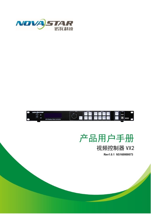
产品用户手册视频控制器VX2Rev1.0.1 NS160000073声明尊敬的用户:欢迎您成为诺瓦产品的使用者,如果本手册为您了解和使用产品带来帮助和便利,我们深感欣慰,我们在编写手册时力求精确可靠,诺瓦会在未通知的情况下随时对手册的内容进行修改和变更,如果您在使用中遇到任何使用问题,或者您有好的建议,请按照手册提供的联系方式联系我们。
对您在使用中遇到的问题,我们会尽力给予支持,对您提出的建议,我们衷心感谢并尽快评估采纳。
版权本手册版权归西安诺瓦科技所有,任何个人或单位未经书面许可,不得以任何形式对文本内容作复制、摘录。
商标是诺瓦科技的注册商标。
视频控制器VX2 用户手册目录1 安全声明 (2)2 型号说明 (2)3 概述 (2)4 外观说明 (3)4.1 前面板 .......................................................................................................................................34.2 后面板 .......................................................................................................................................45 信号连接 (4)6 操作动作说明 (5)7 主界面 (5)8 菜单操作 (6)8.1 第一步输入设置 ......................................................................................................................68.2 第二步快捷点屏 ......................................................................................................................78.3 第三步亮度调节 ......................................................................................................................88.4 第四步输出设置 ......................................................................................................................98.5 画面控制 .................................................................................................................................108.6 声音设置 ..................................................................................................................................118.7 高级设置 .................................................................................................................................128.7.1 双画面 (12)8.7.2 载入箱体配置文件 (13)8.7.3 固化至接收卡 (15)8.7.4 双主控热备份 (16)8.7.5 高级属性 (16)8.7.6工厂复位 (16)8.7.7 预设模板 (16)8.7.8 自定义按键 (17)8.7.9 灰度调节 (17)8.7.10 硬件版本 (17)8.8 通讯设置 .................................................................................................................................178.9 语言设置 .................................................................................................................................188.10 固件升级 (18)9 常见问题 (20)10 技术规格 (2111)安装尺寸 (22)视频控制器 VX2 用户手册8) 视频输出带载能力: 130 万像素;9) 支持 Nova 新一代逐点校正技术,校正过程快速高效;10) VX 2 无须通过计算机软件进行系统配置。
【精品】LED显示屏操作软件用户使用手册-图文(精)

L E D显示屏操作软件用户使用手册-图文(精)LED视窗图文编辑系统用户使用手册二〇一一年五月目录一、概述 (11.1、简介 (11.2、主要功能特点 (1二、安装 (22.1、运行环境 (22.2、安装及卸载 (2三、制作节目 (33.1、界面介绍 (33.1.1、软件界面 (33.1.2、菜单 (33.1.3、工具栏 (63.1.4、节目管理 (73.1.5、属性信息设置 (83.1.6、模拟显示窗口 (93.2、系统参数设置 (93.3、节目制作流程 (113.3.1、新建、编辑工程 (113.3.2、新建、编辑节目 (123.3.3、添加分区内容 (133.3.4、设置节目流水边框 (233.3.5、设置节目属性 (233.3.6、发送工程到显示屏 (24四、其他功能 (264.1、亮度设置 (264.2、定时开关机及校准 (264.3、强制开、关机 (27附件一 LED控制卡接线示意图 (28一、概述1.1、简介LED视窗图文编辑系统软件专为Huaby(华柏图文控制器配套设计,自2007年投放市场,历经几代产品的更新发展,功能日臻完善,操作简单,深受广大用户喜爱。
这款最新推出的LED视窗2011版本是我们在多年从事LED异步控制器研发基础上,通过对大量用户使用习惯调研的基础上,提出的一套最完善的整体解决方案。
该编辑软件从功能和使用上都有了很大的改进。
Huaby(华柏LED通用图文控制卡应用国际最新32位嵌入式技术,使脱机操作更加稳定、方便的同时,带来了硬件指标的全面提升,彻底消除了超长显示模式下显示内容抖动问题,同时Huaby(华柏的精良设计,使该控制系统硬件使用效率非常高,外围元件大大减少,带来成本大幅度降低,通过电源及232通信部分增加了保护设计,消除了带电作业对板卡损伤的隐患,从而大幅提高系统的安全可靠型。
1.2、主要功能特点●支持所有(室内、户外单元板,单色和双基色。
●支持16扫、1/8扫、1/4扫、1/2扫和静态驱动模式(用户可随意选择,智能识别扫描类型。
诺瓦科技LED显示屏视频处理器J6用户手册
J6 User ManualStatementDear users,You are welcome to use the J6, a multi-screen splicing processor of Xi'an NovaStarTech Co., Ltd. (hereinafter referred to as NovaStar).This document is intended to help you understand and use the product. For accuracyand reliability, NovaStar may make improvements and/or changes to this document atany time and without notice. Any problem in use or any good suggestion, pleasecontact us through ways provided in the document. We will do our utmost to solve theproblems and adopt the suggestions after evaluation as soon as possible.User ManualMulti-Screen Splicing Processor J6Rev1.0.1NS160110162Copyright ©2018NovaStarAll rights reserved. No part of this document may be copied, reproduced, extracted ortransmitted in any form or by any means without the prior written consent of Xi’anNovaStar Tech Co., Ltd.Trademarksis a trademark of NovaStar.Contents1 Overview (2)1.1 System Architecture .......................................................................................................................................21.2 Software Installation ......................................................................................................................................22 Appearance (3)2.1 Front Panel ....................................................................................................................................................32.2 Rear Panel .....................................................................................................................................................43 Signal Connection (6)4 Menu Operations (7)4.1 Output Settings ..............................................................................................................................................94.2 Window Settings ............................................................................................................................................94.3 Preset Recall ...............................................................................................................................................104.4 Input Settings ...............................................................................................................................................104.5 Display Control .............................................................................................................................................114.6 Advanced Settings ........................................................................................................................................114.7 Communication Settings ..............................................................................................................................124.8 Language Settings .......................................................................................................................................125 System Mode (13)5.1 Switcher .......................................................................................................................................................135.2 Splicer ..........................................................................................................................................................156 Electrical Parameters (17)7 Installation Dimensions (19)8 Troubleshooting (20)Safety NoticeTo avoid potential hazards, please use this product according to regulations. In theevent of breakdowns, non-professionals are not allowed to disassemble it formaintenance without permission. Please contact the after-sales department ofNovaStar timely.Vertical synchronization: The accuracy level of synchronization.Cascade: Connect multiple J6 units in specific order so as to output images with largerresolution.Note: Terms explained here are only for the chapters below. We will be sorry if theseterms cannot help you.1OverviewDeveloped by NovaStar, J6 is a high-performance multi-screen splicing processor featuring powerful image processing. Multiple video inputs can be overlapped anddisplayed on a display system composed by 4 screens after each of the input is scaled. J6 supports a wide range of inputs which can be spliced into a bigger picture. Based on a powerful FPGA processing platform, J6 supports quick seamless switch between input sources and supports transition effects such as fade, etc., allow you to experience more flexible screen layouts.In addition, J6 can work with V-Can, a new smart management software, to enable more screen splicing effects and better satisfy your needs.1.1 System ArchitectureSoftware Installation1.2 Just like the installation of other common software, install V-Can following the setupwizard.视频源输入 J6控制器显示屏3Signal ConnectionPlease refer to the interface introduction in previous chapter to connect hardware devices (Please turn the power off before connecting signals).J6- S plicerComputerGenlock SourceComputerComputerCameraLED DisplayJ6-SwitcherComputerCameraGenlockSourceComputerComputerCameraMonitorLED DisplayMonitor4Menu Operations After startup, the home screen on the LCD panel is shown as below://Figure 4-1 J6 menu tree4.1 Output SettingsAs shown in the figure below, set the mosaic mode of output images in the “O utput Settings ” menu. Set the resolution of output images i n “Output R esolution ”. Preset resolution and custom resolution are optional. Set the W idth and H eight of current screen in the “ D VI Output ” menu.4.2 Window SettingsThis processor is capable of displaying 6 windows at most and the input source, size, position, priority, input crop,border parameters, etc. of each window are settable. Priority: allows to set the display priority of current window.Input Crop: allows to turn on “Input Crop” a nd display cropped content on LED screen. Border Settings: allows to add or delete borders and set border width and height as well as border color.4.3Preset RecallSwitch presets. Apply the preset parameters directly. 16 presets in total are availablefor users to set and use.Preset RecallJ6 supports 16 user presets. After the preset data is configured, uses can directly usethe configured presets by their names.●Rotate the knob to select a preset you want to load and press the knob to load it.●When you enter the P reset Recall menu, the indicators of number buttons on thefront panel will turn on. You can press the number button to quickly load thecorresponding preset. If the preset No. is a double-digit value, press the twonumbers quickly within 2 seconds. For example, to load P reset 15, press 1and 5quickly within 2 seconds.Preset TemplatesJ6 provides 6 preset templates. Users can use the templates to quickly openwindows to fill the whole screen loaded by J6.Provided preset templates are 1×1, 1×2, 2×1, 1×3, 2×2 and 1×4.4.4Input SettingsInput resolution of signal sources, including DVI, HDMI and DP, can be set. Presetresolutions and custom resolutions are available for users.Preset resolutions include 800×600, 1024×768, 1280×720, 1280×768, 1280×800,1280×1024, 1366×768, 1440×900, 1600×1200, 1680×1050, 1920×1080, 1920×1200,2048×640, 2048×1152, 2048×1536, 2304×1152, 2560×816, 2560×960, 2560×1600and 3840×1080.Preset refresh rates include 50 Hz, 60 Hz, 75 Hz and 120 Hz.Custom resolution includes custom width, custom height and custom refresh rate.● Select “Apply ” and confirm the selection after the settings are done, and then the settings will take effect.●The total number of pixels is not greater than 2.1 million. The width of custom resolution cannot be greater than 3840 and height not greater than 1080.Output modes include: “SingleLink” and “DualLink”.Note:4.5 Display ControlAs shown in the figure below, “OSD” can be turned on/off , and “ T ransition Effect ”( i ncluding fade and cut), “ S witching Time ” , display state and image quality can be set in the “Display Control” menu. Input Color Settings: Select an input source to be adjusted to adjust its brightness, contrast, saturation, hue or reset to defaults.Tip: ● OSD function description: You can turn on/off OSD. Control software is requiredfor adding and setting detailed contents.●Transition effect description: Switching time setting can change the transition time of an effect.MVR Selection4.6 Users can scale up a specific input source, the PVW or PGM to view on the previewmonitor.On the MVR selection menu, rotate the knob to select an input source, the PVW or PGM and press the knob to display the selected target on the monitor in full screen. When you press the knob again, the current scaled display will exit.4.7 Advanced SettingsSystem modes include: “S p licer ” and “S w itcher ”.In synchronous mode, any one of the input sources can serve as synchronous source. Following synchronous sources are selectable: GenLock and any one of the input sources.4.8Communication SettingsCommunication modes include: “USB preferred” and “LAN preferred”.“N etwork”:allows to set IPv4 Config (manual and auto), IP address, and subnet maskor to reset to default network parameters.Tip:●This processor supports two control modes: USB and Ethernet cable. Pleaseselect according to actual needs.●IP and subnet mask can be edited only when network mode is set to “M anual”.4.9Language SettingsJ6 currently s upports “Chinese” and “English”only. Users can switch languages asrequired.“PVW” area is for editing. Different signal sources can be selected. Windows can be added and window parameters can be edited. Six windows can be added at most. Splicing area supports up to 1×2 layout (Splicing mode can be chosen withoutlimitation). Windows can be overlapped. The overlapped area displays the content of the window with higher priority. After the content is edited, result can be previewed on the monitor and can be adjusted.The display parameters set before can be saved as preset, which is convenient for using next time.5System ModeSystem modes include “Splicer” and “Switcher”.I n these two modes, J6 can work with the software V-Can.5.1 SwitcherStep 1: Refer to the hardware connection diagram t o connect hardware devices. Step 2: Start V-Can, connect devices and adjust their parameters. Set system mode to “Switcher”.Step 3: Add windows in editing area and set window parameters. Then output the edited content to LED screen.As shown in the figure below, content in “PGM” area is being displayed on the LED screen. After the content to be output is edited i n the “PVW” area , click the “TAKE” button in the top right corner of the page and then t he content in “PVW” area will bemapped to “PGM” area. LED screen will disp lay the edited content. Xi’anTechCo.,Ltd.5.2 SplicerStep 1: Refer to the hardware connection diagram to connect hardware devices. Step 2: Start V-Can, connect devices and adjust their parameters. Set system mode to“ S plicer ”. Step 3: Add windows in editing area and set window parameters. Then the edited content is displayed on LED screen in real-time.Splicing area supports up to 2×2 layout. (Splicing mode can be chosen without limitation).Different signal sources can be chosen. Windows (six at most) can be added. Window parameters can be edited. Windows can be overlapped. The overlapped area displays the content of the window with higher priority.The display parameters set before can be saved as preset, which is convenient for using next time.7 Installation DimensionsUnit: mm。
诺瓦科技LED显示屏视频控制器J6用户手册英文版

J6 User ManualUser Manual Multi-Screen Splicing Processor J6Rev1.0.1NS160110162Xi ’a n No va S t a r T e c h C o .,L t d .StatementDear users,You are welcome to use the J6, a multi-screen splicing processor of Xi'an NovaStarTech Co., Ltd. (hereinafter referred to as NovaStar).This document is intended to help you understand and use the product. For accuracyand reliability, NovaStar may make improvements and/or changes to this document atany time and without notice. Any problem in use or any good suggestion, pleasecontact us through ways provided in the document. We will do our utmost to solve theproblems and adopt the suggestions after evaluation as soon as possible.Copyright © 2018 NovaStarAll rights reserved. No part of this document may be copied, reproduced, extracted ortransmitted in any form or by any means without the prior written consent of Xi’anNovaStar Tech Co., Ltd.Trademarksis a trademark of NovaStar.X i’a n No v aS t ar Te c hC o.,Lt d.Contents1 Overview (2)1.1 System Architecture ....................................................................................................................................... 2 1.2 Software Installation .. (2)2 Appearance (3)2.1 Front Panel .................................................................................................................................................... 3 2.2 Rear Panel .. (4)3 Signal Connection ........................................................................................................... 6 4 Menu Operations . (7)4.1 Output Settings .............................................................................................................................................. 9 4.2 Window Settings ............................................................................................................................................ 9 4.3 Preset Recall ............................................................................................................................................... 10 4.4 Input Settings ............................................................................................................................................... 10 4.5 Display Control ............................................................................................................................................. 11 4.6 Advanced Settings ........................................................................................................................................ 11 4.7 Communication Settings .............................................................................................................................. 12 4.8 Language Settings (12)5 System Mode (13)5.1 Switcher ....................................................................................................................................................... 13 5.2 Splicer . (15)6 Electrical Parameters .....................................................................................................17 7 Installation Dimensions .................................................................................................19 8 Troubleshooting . (20)Xi ’a n No va S t ar T ec h C o .,L t d .Safety NoticeTo avoid potential hazards, please use this product according to regulations. In the event of breakdowns, non-professionals are not allowed to disassemble it for maintenance without permission. Please contact the after-sales department of NovaStar timely.High voltage danger: The operating voltage range of this product is 100V to 240V AC.Grounding: This product is grounded through the grounding cord of power supply. Please keep the grounding conductor well grounded.Electromagnetic interference: Keep this product far away from magnets, motors and transformers.Moisture proof: Keep this product in a dry and clean environment. In case of liquid immersion, please pull the power plug out immediately.Keep the product away from flammable and explosive hazardous substances.Prevent liquids or metal fragments from dropping into the product in order to avoid safety accidents.Change HistoryGlossary of TermsPreview : Preview includes input preview and preview in switcher mode.OSD : On Screen Display. Preloaded images or texts can be overlapped and displayedon the any area of the screen.Genlock : Synchronization lock, enabling one system or multiple systems in sync with the same video source.Vertical synchronization : The accuracy level of synchronization.Cascade : Connect multiple J6 units in specific order so as to output images with larger resolution.Note: Terms explained here are only for the chapters below. We will be sorry if these terms cannot help you.Xi ’a n t d .1OverviewDeveloped by NovaStar, J6 is a high-performance multi-screen splicing processorfeaturing powerful image processing. Multiple video inputs can be overlapped anddisplayed on a display system composed by 4 screens after each of the input is scaled. J6 supports a wide range of inputs which can be spliced into a bigger picture. Based on a powerful FPGA processing platform, J6 supports quick seamless switch between input sources and supports transition effects such as fade, etc., allow you to experience more flexible screen layouts.In addition, J6 can work with V-Can, a new smart management software, to enable more screen splicing effects and better satisfy your needs.1.1 System Architecture1.2 Software InstallationJust like the installation of other common software, install V-Can following the setupwizard.视频源输入J6控制器显示屏Xi ’a n No va S t ar T ec h C o .,L t d .2 Appearance 2.1 Front PanelX T e ch Co.,L t d.Tip:Additional description for PRESET: Users can rename the presets through the controlsoftware V-Can.2.2 Rear PanelX i v a St a rT e ch Co.,L t d.o t d.X i’an N3Signal ConnectionPlease refer to the interface introduction in previous chapter to connect hardwaredevices (Please turn the power off before connecting signals).J6-SplicerComputerGenlock SourceComputerComputerCameraLED DisplayJ6-SwitcherComputerCameraGenlockSourceComputer Computer CameraLED DisplayMonitorXi ’a n No va S t o .,L t d .4 Menu Operations After startup, the home screen on the LCD panel is shown as below:A//Pure color: The signal source is in use and signals are available. Semitransparent: The signal source is not in use and signals are available.Transparent: The signal source is not in use and no signal is available.B Transparent: The window has input signal and the type of the signal source is displayed in the window.Semitransparent: The window has no input signal. The window will display the input source used to open a window last time, or the default input source. When opening a window using the window template, the window will use the source of the INPUT-C connector as the default source.C Current preset is displayed. Pure color indicates the preset is turned on and semitransparent indicates the preset is not turned on.X’a n No v aS t ar Te c hC o.,Lt d.D Next preset and its turn-on time are displayed. Pure color indicates the schedule of the preset is displayed and transparent indicates the schedule is not displayedE //////Screen structure and size, screen structure supports:1×Output resolutionMaximum supported resolution: 3840×Prompt for test pattern, freeze, black out, etc.No icon is shown when the unit works normally.F//Device connection status: Not connected/Connected tonetwork/Connected to USB/OSD on/OSD off/Transition effects: 21 effects, such as cut and fade/Working mode: splicer/switcher/Button unlocked/button lockedHold down the knob and ESC button simultaneouslythe buttons. All the buttons on the panel are not available after they arelocked.///Genlock is turned off. /The reference source of Genlock is lost orabnormal. /Genlock is locked. /Genlock is to be locked.In the home screen, press the knob to enter main menu (Press the knob to entersub-menus and press ESC to return to the previous menu. Rotate the knob clockwiseto move down and rotate anticlockwise to move up.).Main menu is shown as the figure below. The main menu includes: “Screen Settings”,“Window Settings”, “Preset Recall”, “Input Settings”, “Display Control”, “MVR Selection”,“Advanced Settings”, “Communication Settings” and “Language”.X i’an No v at d.Figure 4-1 J6 menu tree4.1 Output SettingsAs shown in the figure below, set the mosaic mode of output images in the “OutputSettings ” menu. Set the resolution of output images in “Output Resolution ”. Preset resolution and custom resolution are optional. Set the Width and Height of current screen in the “DVI Output ” menu.4.2 Window SettingsThis processor is capable of displaying 6 windows at most and the input source, size,position, priority, input crop, border parameters, etc. of each window are settable. Priority: allows to set the display priority of current window.Input Crop: allows to turn on “Input Crop ” and display c ropped content on LED screen. Border Settings: allows to add or delete borders and set border width and height as well as border color.Xi ’a n No va S t ar T ec h C o .,L t d .4.3 Preset RecallSwitch presets. Apply the preset parameters directly. 16 presets in total are available for users to set and use.Preset RecallJ6 supports 16 user presets. After the preset data is configured, uses can directly use the configured presets by their names.● Rotate the knob to select a preset you want to load and press the knob to load it. ●When you enter the Preset Recall menu, the indicators of number buttons on the front panel will turn on. You can press the number button to quickly load the corresponding preset. If the preset No. is a double-digit value, press the twonumbers quickly within 2 seconds. For example, to load Preset 15, press 1 and 5 quickly within 2 seconds.Preset TemplatesJ6 provides 6 preset templates. Users can use the templates to quickly openwindows to fill the whole screen loaded by J6.Provided preset templates are 1×1, 1×2, 2×1, 1×3, 2×2 and 1×4.4.4 Input SettingsInput resolution of signal sources, including DVI, HDMI and DP , can be set. Presetresolutions and custom resolutions are available for users.Preset resolutions include 800×600, 1024×768, 1280×720, 1280×768, 1280×800, 1280×1024, 1366×768, 1440×900, 1600×1200, 1680×1050, 1920×1080, 1920×1200, 2048×640, 2048×1152, 2048×1536, 2304×1152, 2560×816, 2560×960, 2560×1600 and 3840×1080.Preset refresh rates include 50 Hz, 60 Hz, 75 Hz and 120 Hz.Custom resolution includes custom width, custom height and custom refresh rate.Xi ’a n No va S t ar T ec h C o .,L t d .Note:● Select “Apply ” and confirm the selection after the settings are done, and then the settings will take effect.●The total number of pixels is not greater than 2.1 million. The width of custom resolution cannot be greater than 3840 and height not greater than 1080.4.5 Display ControlAs shown in the figure below, “OSD” can be turned on/off , and “Transition Effect ”(including fade and cut), “Switching Time ”, display state and image quality can be set in the “Display Control” menu.Input Color Settings: Select an input source to be adjusted to adjust its brightness, contrast, saturation, hue or reset to defaults.Tip :● OSD function description: You can turn on/off OSD. Control software is required for adding and setting detailed contents.●Transition effect description: Switching time setting can change the transition time of an effect.4.6 MVR SelectionUsers can scale up a specific input source, the PVW or PGM to view on the previewmonitor.On the MVR selection menu, rotate the knob to select an input source, the PVW or PGM and press the knob to display the selected target on the monitor in full screen. When you press the knob again, the current scaled display will exit.4.7 Advanced SettingsSystem modes include: “S plicer ” and “S witcher ”. Output modes include: “SingleLink ” and “DualLink ”.In synchronous mode, any one of the input sources can serve as synchronous source. Following synchronous sources are selectable: GenLock and any one of the input sources.Xi ’a n No va S t ar T ec h C o .,L t d .4.8 Communication SettingsCommunication modes include: “USB preferred” and “LAN preferred”.“Network”: allows to set IPv4 Config (manual and auto), IP address, and subnet maskor to reset to default network parameters.Tip:●This processor supports two control modes: USB and Ethernet cable. Pleaseselect according to actual needs.●IP and subnet mask can be edited only when network mode is set to “Manual”.4.9 Language SettingsJ6 currently supports “Chinese” and “English” only. Users can switch languages asrequired.X i’an No v aS t ar Te c hC o.,Lt d.5System ModeSystem modes include “Splicer” and “Switcher”. In these two modes, J6 can work with the software V-Can.5.1 SwitcherStep 1: Refer to the hardware connection diagram to connect hardware devices. Step 2: Start V-Can, connect devices and adjust their parameters. Set system mode to “Switcher”.Step 3: Add windows in editing area and set window parameters. Then output theedited content to LED screen.“PVW” area is for editing . Different signal sources can be selected. Windows can beadded and window parameters can be edited. Six windows can be added at most. Splicing area supports up to 1×2 layout (Splicing mode can be chosen withoutlimitation). Windows can be overlapped. The overlapped area displays the content of the window with higher priority. After the content is edited, result can be previewed on the monitor and can be adjusted.The display parameters set before can be saved as preset, which is convenient for using next time.Xi ’a n No va S t ar T ec h C o .,L t d .As shown in the figure below, content in “PGM” area is being displayed on the LEDscreen. After the content to be output is edited in the “PVW” area , click the “TAKE” button in the top right corner of the page and then the content in “PVW” area will be mapped to “PGM” area. LED screen will dis play the edited content.Xi ’a n No va S t ar T ec h C o .,L t d .5.2 SplicerStep 1: Refer to the hardware connection diagram to connect hardware devices.Step 2: Start V-Can, connect devices and adjust their parameters. Set system mode to “Splicer ”.Step 3: Add windows in editing area and set window parameters. Then the edited content is displayed on LED screen in real-time.Splicing area supports up to 2×2 layout. (Splicing mode can be chosen withoutlimitation).Different signal sources can be chosen. Windows (six at most) can be added. Window parameters can be edited. Windows can be overlapped. The overlapped area displays the content of the window with higher priority.The display parameters set before can be saved as preset, which is convenient for using next time.Xi ’a n No va S t ar T ec h C o .,L t d .o v a S t ar Te c hC o.,Lt d.X i’an N6Electrical ParametersXd .X i’a n No v aS t ar Te c hC ot d.7Installation DimensionsUnit: mmXi ’a n No va S t ar T ec h C o .,L t d .8 Troubleshootingt d.。
诺瓦科技LED显示屏发送卡MCTRL4K用户手册

MCTRL4K独立主控产品 版本 : V1. 0 . 3 文档编号 :NS110000429用户手册版权所有©2018西安诺瓦电子科技有限公司。
保留一切权利。
非经本公司书面许可,任何单位和个人不得擅自摘抄、复制本文档内容的部分或全部,并不得以任何形式传播。
商标声明声明欢迎您选用西安诺瓦电子科技有限公司(以下简称诺瓦科技)的产品,如果本文档为您了解和使用产品带来帮助和便利,我们深感欣慰。
我们在编写文档时力求精确可靠,随时可能对内容进行修改或变更,恕不另行通知。
如果您在使用中遇到任何问题,或者有好的建议,请按照文档提供的联系方式联系我们。
对您在使用中遇到的问题,我们会尽力给予支持,对您提出的建议,我们衷心感谢并会尽快评估采纳。
MCTRL4K独立主控用户手册更新历史更新历史MCTRL4K 独立主控用户手册目录目录更新历史 (ii)1安全说明 (1)1.1 存储和运输安全 (1)1.2 安装和使用安全 (1)2概述 (2)3硬件结构 (4)3.1 外观说明 ......................................................................................................................................................43.2 尺寸图 ..................................................................................................................................................... (6)4主界面 (7)5Web 端显示屏配置 (8)5.1 环境配置 ......................................................................................................................................................85.2 界面操作 ......................................................................................................................................................86菜单操作 (10)6.1 亮度调节 ....................................................................................................................................................106.2 输入设置 ....................................................................................................................................................106.2.1 输入模式设置 ..................................................................................................................................... (10)6.2.2 输入分辨率设置 ......................................................................................................................................106.2.3 超大分辨率设置 ....................................................................................................................................... 116.3 屏体配置 ....................................................................................................................................................126.3.1 快捷点屏 ..................................................................................................................................... (12)6.3.2 高级点屏 ..................................................................................................................................... (12)6.3.3 画面偏移 ..................................................................................................................................... (13)6.4 画面控制 ....................................................................................................................................................136.5 高级设置 ....................................................................................................................................................136.5.1 Mapping 功能 ..................................................................................................................................... (13)6.5.2 载入箱体文件 ..................................................................................................................................... (13)6.5.3 监控阈值设置 ..................................................................................................................................... (14)6.5.4 固化至接收卡 ..................................................................................................................................... (14)6.5.5 冗余设置 ..................................................................................................................................... (14)MCTRL4K独立主控用户手册目录6.5.7 HDR (15)6.5.8 硬件版本 (15)6.6 通讯设置 (15)6.7 语言设置 (16)7规格参数 (17)6.5.6 工厂复位 ..................................................................................................................................... (15)MCTRL4K独立主控用户手册 1 安全说明1安全说明本章描述独立主控MCTRL4K的安全说明,目的是保证产品的存储、运输、安装和使用安全。
- 1、下载文档前请自行甄别文档内容的完整性,平台不提供额外的编辑、内容补充、找答案等附加服务。
- 2、"仅部分预览"的文档,不可在线预览部分如存在完整性等问题,可反馈申请退款(可完整预览的文档不适用该条件!)。
- 3、如文档侵犯您的权益,请联系客服反馈,我们会尽快为您处理(人工客服工作时间:9:00-18:30)。
LED视频控制器V900用户手册Rev 1.1.2西安诺瓦电子科技有限公司尊敬的用户:欢迎您成为Nova产品的使用者,如果本手册为您了解和使用产品带来帮助和便利,我们深感欣慰。
我们在编写手册时力求精确可靠,诺瓦会在未通知的情况下随时对手册的内容进行修改和变更。
如果您在使用中遇到任何使用问题,或者您有好的建议,请按照手册提供的联系方式联系我们。
对您在使用中遇到的问题,我们会尽力给予支持,对您提出的建议,我们衷心感谢并尽快评估采纳。
版权本手册版权归西安诺瓦科技所有,任何单位和个人未经书面许可,不得以任何形式对文本内容作复制、摘录。
商标信用是诺瓦科技的注册商标。
安全须知为避免可能的危险,请按规定使用此设备。
如出现损坏,非专业人士请勿擅自打开维修,请及时与本公司售后联系。
高压危险:本产品的工作电压为接地:本产品通过电源的地线与大地相连,请确保接地导体的良好接地。
电磁干扰:设备应远离磁铁、马达及变压器。
防潮:请将设备置于干燥、干净的环境中。
如有液体浸入,请立即拔掉电源插头。
远离易燃易爆危险物品。
禁止液体、金属碎片浸入机器内部,以免引起安全事故。
插座应当装在设备的附近,而且应当便于触及到。
电源线一条DVI线一条VGA线1条USB线一条BNC转AV接头2个说明书一本合格证一张概述V900 是Nova专业级的LED视频控制器,其除了显示屏控制外还具有功能强大的前端视频处理功能。
V900 以优秀的图像质量和灵活的图像控制极大的满足了媒体行业的需求。
V900 具有完备的视频输入接口,包括2路CVBS,2路VGA,1路DVI,1路HDMI,1路YPbPr,1路选配SDI。
部分接口支持的输入分辨率最高可达1080p@60Hz。
V900无须通过计算机软件进行系统配置。
现在只需对一个旋钮和一个按钮进行操作即可完成系统配置,所有操作几步即可完成,这就是我们所倡导的“司机点屏”!V900 是Nova新一代控制器的系列产品,强大的图像处理、专业的图像控制、以及友好的人机界面,使显示屏控制工作从未如此轻松和愉快。
目录第一章功能简介 (3)输入输出接口示意图 (3)前面板控制显示示意图 (4)操作说明 (4)电气参数 (5)第二章信号连接 (6)信号连接 (6)多机连接 (6)第三章菜单操作 (7)主界面 (7)输入设置 (8)快捷点屏 (8)亮度调节 (9)输出设置 (9)画面控制 (11)声音设置 (12)高级设置 (12)双画面 (12)拼接带载 (13)载入箱体配置文件 (14)固化至接收卡 (14)双主控热备份 (14)高级属性 (14)工厂复位 (15)预设模版 (15)自定义快捷键 (15)硬件版本 (15)第四章常见问题 (16)第一章功能简介输入输出接口示意图图1 后面板示意图注:为提高用户体验,接口布局可能会稍作调整,请以实物为准。
前面板控制显示示意图图2 前面板示意图操作说明V900 功能强大,操作简单,所有操作都可以通过一个旋钮和一个返回按键完成。
旋钮:✧主界面下,按下旋钮进入菜单操作界面。
✧菜单操作界面下,旋转旋钮选择菜单,按下旋钮选定当前菜单或者进入子菜单。
✧选定带有参数的菜单后可以通过旋转旋钮调节参数,请注意调节完成后需要再次按下旋钮进行确认。
ESC: 返回键,退出当前菜单或操作。
按键锁定/解锁: 同时长按旋钮和ESC键。
电气参数处理器接口及性能指标见下表:第二章信号连接信号连接请按照第一章功能简介中输入输出接口的介绍连接所需的硬件设备。
(注:信号连接时,请先关闭设备电源。
)图3 V900 信号连接示意图多机连接如需同时控制多台V900,请按下图进行连接。
图4 多机连接示意图第三章菜单操作主界面处理器开机后,LCD屏显示主界面如下:第一行:主画面1、信号源、输入源信号格式;第二行:画中画2、信号源、输入源信号格式;第三行:屏体宽高和亮度;第四行:状态栏,各图标含义如下表中所述:当前控制器为主控;显示“备份”字样时表示为备份当前显示效果为点对点显示当前为缩小模式当前为放大模式画中画关闭画中画开启拼接带载禁用拼接带载启用输出网口(当前为网口按键锁标识,出现此图标时表示当前处于按键锁定状态。
→输出设置四个步骤即可点亮显示屏,且亮度适中,可以开始正常使用。
其他如画面控制、高级设置等菜单可以帮助用户更好地控制LED显示屏。
输入设置用户可以按照自己的需求设置输入源的分辨率,目前仅支持DVI, HDMI两种输入接口可直接在V900上设置其输入分辨率,其他输入接口只能在前端输出设备上进行修改。
输入分辨率可以通过以下两种方式设置:方式一:预设分辨率设置在预设的标准分辨率中选择合适的分辨率(刷新率固定为60Hz)。
如预设中没有,可选择方式二,自定义分辨率。
方式二:自定义分辨率设置旋转旋钮设置自定义宽度(以偶数递增),自定义高度,自定义刷新率,然后选中“应用”,按下旋钮确定并应用,如果不应用,那么自定义的分辨率无效。
快捷点屏快捷点屏的前提条件是:屏体规则(非异型),箱体规则,各箱体带载大小相同。
快捷点屏操作步骤:第1步显示屏上电,如箱体显示正常,进入第2步,如显示不正常,则必须先载入箱体文件,并固化至接收卡,具体操作请查看高级设置;第2步进入“快捷点屏”的子菜单,转动旋钮,分别进入其他选项进行设置;第3步根据屏体实际情况,设置V900带载的箱体行数和列数;第4步设置网口1带载箱体数,设备对网口的带载数有一定的限制,具体请看屏体设置注意事项a);第5步设置屏体走线方式,请注意查看注意事项c)、d)、e);注意:a)如有带载的网口数为n(n≦4),则前n-1个网口带载的箱体数必须相等(如各网口带载箱体数不相同,请使用软件进行配置),且必须是箱体行数或列数的整数倍,同时大于等于第n个网口的带载箱体数。
举例:网口1、网口2、网口3都有带载,那么网口1与网口2的带载箱体数必须相同,且必须是箱体行数或列数的整数倍,因此屏体设置时仅需要根据实际情况设置网口1带载箱体数;网口3带载接收卡数则≤网口1的带载箱体数。
b)如果是异型箱体、箱体大小不同、异型屏,需要连接软件NovaLCT-Mars配置显示屏;c)设置走线方式时,旋转旋钮可实时预览显示屏上不同走线的效果,如果满意须按下旋钮来保存该设置,直接按返回键则退出当前操作,不会保存预览的走线方式;d)设置走线方式时,必须确保每个网口的走线能顺着同一个方向向下连接;e)设置走线方式时,必须确保网口1的起始位置是整个走线的起始位置;f)V900最大可带230万个像素(2048x1152@60Hz)。
横向带载最宽可达3840个像素点(此时屏体最大为3840x600@60Hz),纵向最高可带载1920个像素点(此时屏体最大1200x1920@60Hz)。
亮度调节返回主菜单界面,按下旋钮,选中亮度调节菜单的对应数值,转动旋钮调节亮度值。
输出设置用户可以根据需要选择不同的输出设置,支持以下三种方式:第一种:禁用缩放,即输出图像与输入图像大小一致,原比例进行输出。
该选项适用于要求点对点显示的应用场合。
根据需要可以设置画面水平偏移和垂直偏移,此时显示内容在屏体上会向左或者向上移位。
如果输入分辨率在某个方则屏体在该方向上会有不被点亮的现如果输入分辨率在某个方则会出现输入的内容在该方向上显示第二种:自动全屏播放。
此时【启用缩放】为启用,【自动全屏缩放】为启用。
自动全屏缩放时,输入内容被完全缩放到屏体大小,输入内容自适应显示屏大小。
此模式适合演播内容全屏播放的情况。
第三种:自定义缩放。
此时【启用缩放】设为启用,【自动全屏缩放】设为禁用。
自定义缩放需要执行以下操作步骤:第1步设置输入截取,即从输入的图像中,截取输入图像的某个起始点之后的部分感兴趣的画面在显示屏上显示。
一般需要设置水平宽度(小于等于输入源横向分辨率),垂直高度(小于等于输入源垂直分辨率),水平起始和垂直起始。
第2步设置输出窗口,窗口尺寸需小于等于显示屏大小。
设置好窗口后,图像只能在窗口范围内自适应大小显示,用于在显示屏上预留边框或者是限制画面播放区域的应用场合。
按照以上两步进行设置后,显示屏仅会在设定的区域内显示输入截取的内容,如下图所示:图5 自定义缩放效果图画面控制正常显示:正常播放当前输入源的内容。
画面黑屏:显示屏黑屏不显示。
画面冻结:冻结当前播放内容。
如果当前源信号丢失,则会出现黑屏。
测试画面:包含纯色和线条共八种测试画面。
画质调整:根据要求设置画面的对比度、饱和度、色调、色温、红色亮度、绿色亮度、蓝色亮度和Gamma值,调整到满意之后可以将参数固化到接收卡。
通道切换特效:设置画面切换时的效果,包含瞬切、淡入淡出和关闭。
选定需要的效果后,需要按下旋钮才可以生效。
通道切换特效功能才可以生效。
声音设置控制音频的启用与禁用,音量大小与伴音模式。
例如,要使用由Audio In口输入的音频,则要先启用音频,然后把伴音模式选为固定。
如果要使用从HDMI进来的声音,则启用音频后,把伴音模式设为跟随模式,再把源切到HDMI,我们听到的声音就是从HDMI进来的声音了。
高级设置在高级设置里包含了多个主要功能的设置选项,如双画面设置、拼接带载、载入箱体配置文件、固化至接收卡、双主控热备份、高级属性、工厂复位、预设模块、自定义按键、硬件版本等。
下面章节将详细讲述每个功能。
双画面设置双画面的开关和关闭,主画面和画中画的输入源,以及画中画的大小、位置和双画面输入截取设置。
主画面输入源/画中画输入源:主画面和画中画的输入源切换与主面板上的输入源切换按钮作用相同。
双画面截取设置:从设置的起始位置开始截取画面显示到画中画窗口,大小为设置的水平宽度和垂直高度。
需先启用画中画功能,然后才能设置水平宽度、垂直高度、水平起始和垂直起始。
拼接带载当显示屏点数超过单台V900的带载能力时,就需要使用拼接带载功能。
首先需要开启拼接带载功能,然后设置大屏的总点数,再设置每台V900带载的区域大小,以及带载区域的起始位置。
所有拼接V900 带载的区域大小加起来即大屏的总点数。
图 6 拼接带载连接示意图 拼接实例:显示屏总点数为3000×1000,超过了单台V900的带载能力。
可以使用拼接带载功能,使用两台V900进行拼接处理。
连接方法请见右图,具体参数设置如下表。
用缩放】设为启用,【自动全屏缩放】设为禁用。
载入箱体配置文件V900与PC连接,在PC上运行NovaLCT-Mars,将之前保存好的箱体配置文件导入到控制器。
1)保存箱体配置文件接收卡配置完成后,点击,将箱体配置文件(.rcfg)保存至PC本地文件。
2)将箱体配置文件导入到V900。
如下图所示:3)载入箱体配置文件固化至接收卡将V900的所有当前配置固化至接收卡,断电后数据不会丢失。