耀华-串联式接线盒说明
带外串联间隙型线路避雷器说明书

带外串联间隙型线路避雷器安装使用说明书广州华盛避雷器实业有限公司1用途及特点带外串联间隙型线路避雷器(以下简称避雷器)与线路绝缘子(串)并联安装使用,特别在雷电活动强烈或降低杆(铁)塔接地电阻困难的线段,可有效降低线路雷击跳闸事故率。
避雷器具有放电分散性小、密封性能好、防爆、耐污、体积小、重量轻、运输及安装方便等优点。
2 工作原理因串联间隙的隔离作用,在系统正常运行时,本体基本处于“休息”状态,大部分工频电压由串联间隙承担,由于串联间隙对工频和操作过电压的耐受特性,在工频和操作过电压的作用下,避雷器不动作,只有在雷电过电压的作用下,串联间隙才击穿放电,避雷器动作,限制了雷电过电压,从而确保了被保护的线路绝缘子(串)不发生闪络,并在雷电冲击过后,串联间隙可靠切断工频续流,系统恢复正常运行。
3 正常使用条件a)环境温度不高于+45℃,不低于–40℃;b)太的辐射;c)海拔高度不超过2000m;d)电源频率不小于48Hz,不超过62Hz;e)地震烈度8度及以下地区;f)最大风速不超过35m/s;4 型号及含义5.技术性能避雷器主要技术性能见表1。
6.验收试验用户应对交货的避雷器进行验收试验:⑴按装箱单检查随机文件及附件,应齐全。
⑵测量本体直流1mA参考电压及0.75倍直流1mA参考电压下泄漏电流应符合表1规定(注意:在潮湿及表面污秽时,应采用屏蔽法测量)。
⑶测量串联间隙距离应符合表1规定。
7.贮存避雷器应贮放在环境温度为–40℃~ +45℃、干燥通风、无酸碱及其它有害物质的库房中保存。
8.安装⑴避雷器外形结构及安装尺寸,见图1。
⑵避雷器与被保护的线路绝缘子(串)并联安装使用。
可悬垂安装、水平安装、斜装或其组合方式,依据塔型及实际需要确定,见图2~9。
(a) 悬垂安装悬垂安装于直线塔时,安装支架(杆塔为用抱箍安装于水泥杆上的单支角钢,其悬挂避雷器端用钢索斜拉,铁塔为安装于塔横担上的三角支架,门型杆塔、酒杯型铁塔、猫头型铁塔等单回路塔的中相则可为安装于塔顶的单支角钢)应沿线路方向抬高伸出,35kV、110kV、220kV避雷器与线路绝缘子(串)间的净距离最小值分别为360mm、800mm、1520mm,避雷器与输电导线宜采用并沟线夹或T形线夹连接,安装好后避雷器的最低点应不低于同相输电导线。
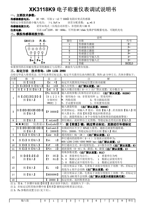
耀华XK3118K9电子称重仪表调试说明书
Z:开机置零范围
0 2% 4% 10% 20% 100% —— —— —— —— F.S
注 4:分度值切换显示在默认设置下无效。
四、定时关机设置
在称重状态下按【打印设置】键,输入密码【88】,再按【输入】键,仪表显示【SECU 0】,表示进入定时关机
设置,可以修改密码及定时关机日期,步骤如下:
步骤
操作
3
按【0】【按9】【 【输0】【入9】】【0】【9】【L09.09.09】输 例入 如关 :0机90日90期9
4
称重状态 关机日期修改完毕
注 1:请妥善保存修改过的密码,若丢失后不可进入,只能返厂维修或初始化存储芯片(默认设置密码为
“888888”);
注 2:关机日期默认设置为“999999”,表示不使用定时关机功能;
自检完毕进入称重状态,打开仪表背后标定盖,标定开关拨至仪表内侧位置,预热 15 分钟左右,具体步骤如下:
步骤
操作
显示
注
解
1
按【功能】
【d *】 标定开关拨到允许标定位置后按功能键
2 按【1】【0】按【输入】 【d 10】 输入分度值( 出厂默认设置:10)
3 按【 0 】按【输入】 【dC 0 】 输入小数点位数( 0~4 ) 出厂默认设置:无小数点 0
输入值
0
1
2
3
4
5
6
7
8
9 单位
W:判稳范围
0.5 1.0 1.5 2.0 2.5 3.0 3.5 4.0 4.5 5.0 uV
X:零点跟踪范围
0 0.5 1.0 1.5 2.0 2.5 3.0 3.5 4.0 4.5 E
Y:手动置零范围
0 2% 4% 10% 20% 100% —— —— —— —— F.S
防爆接线盒的选用及接线方法
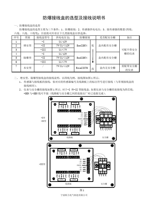
防爆接线盒的选型及接线说明书一、防爆接线盒的选型防爆接线盒的选型主要为三个条件:1、防爆级别;2、传感器供电电压;3、接传感器的数量(四线、六线、八线、十线等)。
目前我司共有以下几类接线盒以供选择: 序号 类别接线盒型号供电电压Ui 防爆级别 是否配安全栅 备注1 增安型 -I Ui>12V ExeIIBT4低高盒内配有安全栅可配不带安全栅的仪表2 -II 7V<Ui ≤12V3 -III Ui ≤7V4 隔爆型 -I Ui>12V ExdIIBT4 盒内配有安全栅5 -II 7V<Ui ≤12V6 -III Ui ≤7V 7本安型 /7V<Ui ≤12VExiaIICT6 盒内无安全栅需配带安全栅的仪表二、 增安型、隔爆型接线盒的接线说明:以四线为例,接线图如图1所示;1、 传感器与接线板的接线:依对应的传感器编号及线路板上的标注符号进行接线(与常规接线盒的接线相同);2、 仪表与安全栅的接线如图1所示,对于-I 和-II 型接线盒,如果仪表与安全栅的连接线为四芯线,+SEN 与-SEN 线可不接(线路板与安全栅之间的连接出厂时已连接完成)。
(黑)EXC- (黄)SEN- (白)SIG-屏蔽线 SHIELD (绿)SIG+ (蓝)SEN+ (红)EXC+线路板白SIG-黑EXC-黑EXC-白SIG-SHIELD绿SIG+红EXC+红EXC+绿SIG+SHIELD传感器4传感器3安全栅212112白S I G -S H I E L D绿S I G +红E X C +红E X C +绿S I G +S H I E L D白S I G -黑E X C -黑E X C -传感器1传感器2绿 白红 黑蓝 黄434334-II型-I型SEN+SEN-SIG+SIG-EXC+EXC-安全栅传感器3传感器4线路板传感器2传感器1 (黑)EXC- (黄)SEN- (白)SIG-屏蔽线 SHIELD (绿)SIG+ (蓝)SEN+ (红)EXC+黑EXC-SHIELD白SIG-黑EXC-红EXC+绿SIG+绿SIG+白SIG-SHIELD红EXC+黑E X C -S H I E L D绿S I G +红E X C +黑E X C -白S I G -绿S I G +白S I G -S H I E L D红E X C +2SIG+EXC+EXC-21SIG-14433-III型图1三、 本安型接线盒的接线方法与常规接线盒的接线相同。
防爆接线盒使用说明
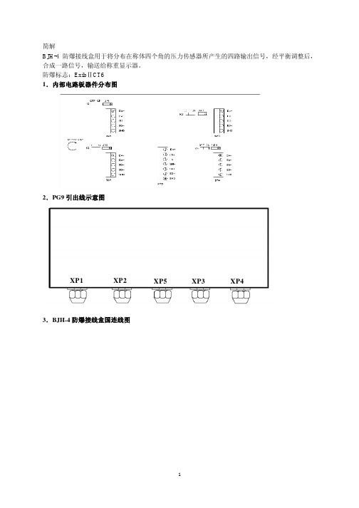
简解BJH-4防爆接线盒用于将分布在称体四个角的压力传感器所产生的四路输出信号,经平衡调整后,合成一路信号,输送给称重显示器。
防爆标志:ExibⅡCT61.内部电路板器件分布图2.PG9引出线示意图XP1 XP2 XP5 XP3 XP43.BJH-4防爆接线盒国连线图4.使用方法1. VR1~VR4:可变电阻,用于调整平衡,顺时针旋转时,显示器上的重量数字将增加。
2. K1~K4:a.跨接器接在ON端,用于调整VR,使四个压力传感器输出平衡.b.跨接器接在OFF端,开始主调整时用于分辨出四个压力传感器的最小灵敏的一个3. XP1~XP4:四个传感器电信号输入端子,按要求正确接上信号线4. XP5:经平衡调整后,合成信号输出的接线端,该端信号送给称重显示器。
5. XP1、XP2、XP3、XP4:四个传感器的电信号输入端子,可按要求正确地接上信号线6. XP5:经调整后,合成信号输出的接线端,该端的信号送往仪表。
5.平衡调整1. 将四个传感器的信号线接在接线柱上,让所有短路块插在K1、K2、K3、K4的左边并把电位器拧至电阻值适中,记下四个传感器接线柱与承载器上传感器位置的对应关系,把输出线接往仪表。
例如:XP1:左上角XP3:右上角XP2:左下角XP4:左下角2. 依次在承载器四个角放置同一重物,记录四个传感器在显示器上不同的重量值,从大到小排列。
3. 让所有短路块插在K1、K2、K3、K4的右边,在承载器最大的一角电位器往逆时针方向拧,承载器最小的一角电位器往顺时针方向拧。
4. 重复第2步和第3步直到承载器四个角放置的重物在仪表上显示一致。
备注:a. 在调试中的重物应大于满量程的20%,否则秤的精度将会降低。
b.在调试中发现接线柱的电位器拧至电阻值最小或电位器拧至电阻值最大,还不能调好秤的平衡,应检查四个传感的灵敏度离散性是否太大。
6. BJH-4 防爆接线盒尺寸7. 成套性1 BJH-4 防爆接线盒 1 台2 使用说明书 1 本3 产品合格证 1 张。
Renewable Energy 高效互联技术系列 - 光伏系统接线盒说明书

500 02/2021 Subject to change without notice. All rights reserved by Hirschmann Automotive GmbH.
Technical Data
Materials
Housing:
Color:
Weatherproof resistance against UV radiation and ozone Black
Hirschmann Automotive GmbH Division Renewable Energy Oberer Paspelsweg 6-8 6830 Rankweil, Austria Telephone: +43 5522 307-0 Fax: +43 5522 307-555 info@
Processing
Processing:
Manual and automatic processing possible
Standards
IEC 62790:2014 UL 3730
Contact us! Let’s work together in defining your competitive advantage to succeed in the global market environment.
RENEWABLE
ENERGY
Electrical Features
Rated Voltage: Rated Current: Diodes: Safety Class:
1000 VDC EN, 1000 VDC UL Up to 13 A (depends on diode type) 3 Class II
ALTINEX Tilt 'N Plug Jr. 接线盒说明书

MANUAL PART NUMBER: 400-0110-006TNP151/152/162Tilt ‘N Plug Jr.Interconnect BoxesTNP121Front View TNP151 Front ViewINTRODUCTIONYour purchase of the Tilt ‘N Plug Jr. Interconnect Box is greatly appreciated. We are sure you will find it reliable and simple to use.Superior performance for the right price, backed by solid technical and customer support is what ALTINEX has to offer.The product you are holding in your hands is designed using state-of-the-art technology and is superior to anything available on the market. You will find this and our other products reliable, long lasting, and simple to operate.We are committed to providing our customers with signal management solutions to the most demanding audio-visual installations at very competitive pricing.We appreciate your selection of our products and are confident that you will join the ranks of our many satisfied customers throughout the world.TABLE OF CONTENTSPage PRECAUTIONS / SAFETY WARNINGS (2)GENERAL (2)INSTALLATION PRECAUTIONS (2)CLEANING (3)FCC / CE NOTICE (3)ABOUT YOUR TILT ‘N PLUG JR.™ (3)TECHNICAL SPECIFICATIONS (4)TILT ‘N PLUG JR.™ DIMENSIONS (5)FACEPLATE DESCRIPTIONS (7)MOUNTING (8)INSTALLATION PROCEDURES (8)ALTINEX POLICY (9)LIMITED WARRANTY / RETURN POLICY (9)CONTACT INFORMATION (9)1 Please read this manual carefully before using your Tilt ‘N Plug Jr.™ Interconnect Box. Keep this manual handy for future reference. These safety instructions are to ensure the long life of your Tilt ‘N Plug Jr.™ and to prevent fire and shock hazard. Please read them carefully and heed all warnings.1.1 GENERAL•Unauthorized personnel shall not open the unit since there are high-voltagecomponents inside.•Qualified ALTINEX service personnel, ortheir authorized representatives mustperform all service.1.2 INSTALLATION PRECAUTIONS•For best results, place the Tilt ‘N Plug Jr.™Interconnect Box in a dry area away fromdust and moisture.•To prevent fire or shock, do not expose this unit to rain or moisture. Do not place theTilt ‘N Plug Jr.™ Interconnect Box in directsunlight, near heaters or heat radiatingappliances, or near any liquid. Exposure todirect sunlight, smoke, or steam can harminternal components.•Handle the Tilt ‘N Plug Jr.™ Interconnect Box carefully. Dropping or jarring candamage the bezel.•Never place fingers inside the opening on each side of the unit. This action couldcause serious injury because of the sharpedges inside of the Tilt ‘N Plug Jr.™.•Do not place heavy objects on top of the Tilt ‘N Plug Jr.™. Do not use excessiveforce to push down on the top of the unit.•To turn off the main power, disconnect the power cord, which powers the power socketon the Tilt ‘N Plug Jr.™ pop up panel only.The power outlet used should be installedas near to the equipment as possible andshould be easily accessible.•We recommend using wall outlets with a Ground Fault Circuit Interrupter (GFCI) formaximum protection.•Install all cables according to the instructions. Do not force or pull out anycable or power cord that is attached to theTilt ‘N Plug Jr.™ Interconnect Box.1.3 CLEANING•Surfaces should be cleaned with a dry cloth.Never use strong detergents or solvents,such as alcohol or thinner. Do not use a wetcloth or water to clean the unit.1.4 FCC / CE NOTICE•This device complies with part 15 of the FCC Rules. Operation is subject to thefollowing two conditions: (1) This devicemay not cause harmful interference, and (2)this device must accept any interferencereceived, including interference that maycause undesired operation.•This equipment has been tested and found to comply with the limits for a Class A digitaldevice, pursuant to Part 15 of the FCCRules. These limits are designed to providereasonable protection against harmfulinterference when the equipment isoperated in a commercial environment. Thisequipment generates, uses, and can radiateradio frequency energy and, if not installedand used in accordance with the instructionmanual, may cause harmful interference toradio communications. Operation of thisequipment in a residential area is likely tocause harmful interference in which casethe user will be required to correct theinterference at his own expense.•Any changes or modifications to the unit not expressly approved by ALTINEX, Inc. couldvoid the user’s authority to operate theequipment.2 Tilt 'N Plug Jr. ™'s are members of a family of compact interconnection solutions designed for installation into a table in a presentation system. These products are designed for mounting into a table, podium, or other furniture to provide a way of connecting audio/visual equipment on top of the furniture to a presentation system below the furniture. All use the same core element; a multimedia input plate that can be "tilted" open when needed and pushed closed when not needed.The TNP122/142/ 152/162 incorporates two Tilt ‘N Plug Jr.™ individual tower modules, the TNP123 incorporates three individual modules and the TNP124 incorporates four individual modules. Each module can be operated independently; the TNP124/152 can service from one to four users simultaneously. During installation of the TNP122/123/152/162, the individual tower modules can be reversed to face opposite directions through a simple field-modification to the bezel. This alternative configuration is handy for applications in which the TNP122/123/152/162 needs to service two sides of a table simultaneously. Note that the TNP142 is the same as a TNP122 but with the modules factory-installed facing in opposite directions.The TNP131 is the same as a TNP121 but with a round bezel instead of square. The TNP162 is a dual module configuration with a TNP121 module and a TNP151 module side by side. The TNP124 is a quad TNP121 with two rows of twin modules facing in opposite directions; the modules in the TNP124 cannot be reversed.The TNP421/431/441/451 are international models with power connectors for specific countries. The TNP421 has a standard "Schuko" receptacle formost European countries, the TNP431 is for the U.K., Singapore and Hong Kong, the TNP441 is for Australia and New Zealand and the TNP451 is for South Africa. Versions of the TNP121/122/123/124/131/142 with a universal IEC320 connector instead of the U.S. power connector are also available.All signals are passed through the input plate to cables on the underside of the table without passing through any circuitry. In some applications, the use of additional ALTINEX signal management solutions —such as computer video interfaces, distribution amplifiers, and switchers — may be desirable.The input plate on the Tilt ‘N Plug Jr.™ is accessed by pushing down on the top cover, which will then auto-tilt open into view with help from a pneumatic spring inside the unit. Once opened, the input plate remains securely in place. The input plate is hidden by pressing down on the top cover until the latching mechanism engages. In its closed position, the top panel lies flush with the table top, held in place by the latching mechanism.All Tilt ‘N Plug Jr.™ solutions come with a standard top and bezel offering a high quality matte black finish.Other optional finishes — Fine Antique Brass, Satin Blush White Gold, Fine Antique Chrome, Antique Copper, Crystallite Copper, Bright Gold, Bright Silver and Brushed Aluminum— are available on a custom order basis. Also, special bezel configurations may be available for large custom orders. Please contact an ALTINEX representative to discuss custom options.3 Specifications are subject to change.See for up-to-date information.MECHANICAL TNP121/131/TNP151 WidthDiameter (TNP131)4.60 in. (117 mm)5.75 in. (146 mm) Height, opened 5.50 in. (140 mm) Depth (TNP121/151) 4.90 in. (124.5 mm) Finish Matte BlackT° Operating10°C-35°CT° Maximum40°CHumidity90% non-condensingTable 1. TNP121/131/151 MechanicalMECHANICAL TNP122/124/142/152/162 Width8.70 in. (221 mm) Height, opened 5.50 in. (140 mm) Depth 4.90 in. (124.5 mm) Finish Matte BlackT° Operating10°C-35°CT° Maximum40°CHumidity90% non-condensingTable 2. TNP122/124/142/152/162 MechanicalMECHANICAL TNP123Width12.80 in. (325 mm) Height, opened 5.50 in. (140 mm) Depth 4.90 in. (124.5 mm) Finish Matte BlackT° Operating10°C-35°CT° Maximum40°C Humidity90% non-condensing Table 3. TNP123 MechanicalMECHANICAL TNP421/431/441/451 Width 5.70 in. (145 mm) Height, opened 6.37 in. (162 mm) Depth 5.20 in. (132 mm) Finish Matte BlackT° Operating10°C-35°CT° Maximum40°C Humidity90% non-condensing Table 4. TNP421/431/441/451 MechanicalELECTRICAL (Single outlet panel)TNP121/122/123/124 TNP131/142/162Power Rating (pass through power connectors)110VAC, 60Hz, 5A per connectorTable 5. TNP121/122/123/124/131/142 Electrical ELECTRICAL(Dual outlet panel)TNP151/152/162Power Rating (pass through power connectors)110VAC, 60Hz, 2.5A per connectorTable 6. TNP151/152 Electrical5MOUNTING DIAGRAM6 Diagram 3: Mounting a Tilt ‘N Plug Jr.™Support bracket Support bracketTable securingscrewTable securingscrewTable top87 Step 1.Cut an opening into the table’s surface.Refer to the ALTINEX website at for table cutoutrequirements .Note: The table can be 3 inches or thinnerin thickness. Always confirm dimensionsbefore cutting to insure that specificationshave not changed.Step 2.Insert the your Tilt ‘N Plug Jr.™ into the table cutout.Step 3.Place the support brackets under the table and place them between the supportmount grooves on the side of the your Tilt‘N Plug Jr.™. Attach the brackets to thegroove at the desired height and securethem to the bottom of the table using the#6-32 screw. There are two supportbrackets for each module, one for eachside of the unit (see Diagram 3). For theTNP124 model, only the outer sides ofeach module will have a bracket placed inthe grooves for a total of four.Step 4.Secure the cables by using the provided cable clamps and screws. Pass the powercord from the bottom of the housing andattach it to the table using the cable clampand screw supplied with the your Tilt ‘NPlug Jr.™. Leave enough slack in theservice loop to allow for easy opening andclosing, but not too much as to causeexcess drooping of the service loop.Step 5.Connect the appropriate cables with the correct input connectors on the bottom ofthe unit.Step 6.Once you have applied power and connected the proper cables on the bottomof the unit you may raise the unit. To raisethe Tilt ‘N Plug Jr.™ into position, pushdown on the front of the top cover; thelatching mechanism will then release,allowing the pneumatic spring to raise itinto position.Step 7.To lower the unit, push on the top of the Tilt ‘N Plug Jr.™ until it locks into place.8 The Tilt ‘N Plug Jr.™ supplied unit was carefully tested and no problems were detected. However, we would like to offer the following suggestions:•Please make sure that the highest quality network cables are used.•Make sure that no cable or power cord is damaged or pinched. If there has beendamage, then do not use the Tilt ‘N Plug Jr.™.Immediately contact the ALTINEX CustomerService Department to have the unit repaired.9 9.0 LIMITED WARRANTY / RETURN POLICYPlease see the Altinex website at for details on warranty and return policy.9.1 CONTACT INFORMATIONALTINEX, INC.592 Apollo StreetBrea, CA 92821 USATEL: 714-990-2300TOLL FREE: 1-800-ALTINEXWEB:E-MAIL:*********************FAX: 714-990-3303。
Ex-JXH-DD-隔爆型数字接线盒 说明书

Ex-JXH-DD-□隔爆型数字接线盒说明书2016年6月版●使用前请仔细阅读本产品说明书●请妥善保管本产品说明书,以备查阅宁波柯力传感科技股份有限公司安全监督站(NEPSI)使用说明书补充说明防爆站审核后对说明书的补充内容,如以下说明书所列内容与下列内容不一致,应以下列条款为准:由宁波柯力传感科技股份有限公司生产的Ex-D11-C防爆型电子称重仪表经国家级仪器仪表防爆安全监督站(NEPSI)检验认可,防爆安全性能符合GB3836.1-2010、GB3836.1.2010和GB3836.4-2010的有关要求,防爆标志为ExdIBT6Gb,防爆合格证号为GYB16.1696X,用户在使用安装该产品时,需注意以下事项:1)、该产品的使用环境温度范围为:(-20~+40)℃。
2)、产品安装、使用和维护严格遵守“严禁带电开盖”的原则。
3)、选用的阻燃密封电缆护套外径应与密封圈内径相适应(Φ8-Φ8.5),使用时压紧螺母应可靠旋紧。
冗余电缆口用封堵件进行封堵。
4)、产品设有接地端子,用户在安装使用时应可靠接地。
6)、使用现场不存在对铝合金外壳有腐蚀作用的有害气体。
7)、用户不得自行更换产品的零部件,应会同产品制造共同解决运行中出现的故障,以杜绝损坏现象的发生。
8)、产品的安装、使用和维护应同时遵守产品说明书、GB3836.13-1997“爆炸性气体环境 用电气设备 第13部分:爆炸性气体环境用电气设备的检修”、GB3836.15-2000“爆炸性气体环境用电气设备 第15部分;危险场所电气安装(煤矿除外)”、GB3836.16-2006“爆炸性气体环境用电气设备 第16部分:电气装置和检查和维护(煤矿除外)及GB50257-1996电气装置安装工程爆炸和火灾危险环境电气装置施工及验收规范”的有关规定。
使用注意事项 由宁波柯力传感科技股份有限公司生产的Ex-JXH-DD-8/Ex-JXH-DD-10/Ex-JXH-DD-12隔爆数字接线盒经国家级仪器仪表防爆安全监督检验站(NEPSI)检验认可,防爆安全性能符合GB3836.1-2010、GB3836.2-2010和GB3836.4-2010的有关要求,防爆标志为Exd[ia IICGa]IIBT6Gb,防爆合格证号为xxxxxxx,用户在使用安装产品时,需注意以下事项:▲系统所有关联设备及配件请按防爆安全标准选用、安装、调试。
XK3190-C602 称重显示控制器 说明书

仪表安装方法
拆下仪表后部两侧的两只 M4 固定螺钉,取下铝制压条,将仪表插 入仪表盘的安装孔,再将压条插入,用 M4 螺钉压紧。
仪表的拆卸和装配
改变模拟量输出形式或 RS422/RS485 上、下拉电阻和终端电阻时, 需要打开仪表,在主板或电源板上调整相应跳线的位置。请按以下方法 小心拆卸和装配仪表,避免损坏。
2
C 602 前言
前言
本手册的使用说明
本手册是供 XK3190-C602 仪表的使用操作人员和安装调试人员使用 的完全版安装维护手册。设备操作人员可使用 C602 仪表的《设备操作 手册》。
使用本手册时,可以先粗略地翻看一下,先重点读与您当前工作最 相关的内容,暂时不需了解的内容可以跳过去,对仪表有初步的了解后 再进一步全面细读。
2
C 602 第一章 概述
第一章 概 述
XK3190-C602 称重显示控制器采用 Cortex M3 内核的 32 位 ARM 处理 器及高精度Σ-△ A/D 转换器件,采用嵌入式实时操作系统对重量信号 进行转换、处理和显示,最高可达 200 次/秒的转换速度。本显示器可 方便地与电阻应变式称重传感器连接组成配料秤、定量包装秤、分选秤 等,适用于各种高速度与高精度称重要求的控制场合。
文中有灰色底纹的部分是强调的内容,请特别关注。 手册中键名用【 】括起来。“【SET 1】参数”表示第 1 组参数。
程序版本说明
2.04 版增加了可选的密码功能。可在进入参数 1 时输入密码。增加 了打印去前导零的选择。在设置参数时可用复合键【→】+【↑】返回 上一参数。辅助显示可选择显示定量秤下料重量。大屏幕可显示辅助显 示锁存的重量。
- 1、下载文档前请自行甄别文档内容的完整性,平台不提供额外的编辑、内容补充、找答案等附加服务。
- 2、"仅部分预览"的文档,不可在线预览部分如存在完整性等问题,可反馈申请退款(可完整预览的文档不适用该条件!)。
- 3、如文档侵犯您的权益,请联系客服反馈,我们会尽快为您处理(人工客服工作时间:9:00-18:30)。
耀华串联式接线盒使用说明
一、概述
本接线盒采用串联调整电位器的方式来修正四角误差。
采用20Ω高精度多圈(20圈)电位器。
接线方式为压接、焊接可选。
二、预调
1、在不接传感器的情况下,用数字式万用表电阻档测量各电位器的电阻值。
表棒搭在OUT接线端子的E+和X接线端子(X为A、B、C、D、E、F、
G、H)的E+上即可测得Xr电位器的电阻值。
2、把各个电位器的电阻值都调成一样。
(顺时针调节电位器,则电位器的电
阻值变大;逆时针调节电位器,则电位器的电阻值变小)
三、接线
E+表示供桥正;E-表示供桥负;IN+表示信号正;IN-表示信号负;接屏蔽线的屏蔽层。
A、B、C、D、E、F、G、H接线端子接传感器,OUT接线端子接仪表。
四、修正四角误差
Xr电位器对应的是X接线端子所连的传感器(X为A、B、C、D、E、F、
G、H)。
顺时针调节电位器,则电位器的电阻值变大,所对应的传感器所占
的比重也变小。
逆时针调节电位器,则电位器的电阻值变小,所对应的传感器所占的比重也变大。
(如果某个角偏大,则应顺时针调节对应的电位器;如果某个角偏小,则应逆时针调节对应的电位器)
上海耀华称重系统有限公司
2003/5/23。