接线盒说明书
欧特顿GUE和GUB接线盒说明书
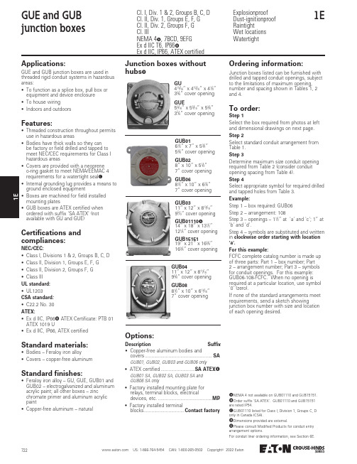
1E1GUE and GUB junction boxesExplosionproof Dust-ignitionproof Raintight Wet locations WatertightCl. I, Div. 1 & 2, Groups B, C, D Cl. II, Div. 1, Groups E, F, G Cl. II, Div. 2, Groups F, G Cl. IIINEMA 4A , 7BCD, 9EFG Ex d IIC T6, IP66BEx d IIC, IP66, ATEX certifiedA NEMA 4 not available on GUB01110 and GUB15151.B Order suffix 'SA ATEX'. GUB01110 and GUB15151are rated IP54.C GUB01110 listed for Class I, Division 1, Groups C, Donly in Canada (CSA).D Dimensions provided are external.E Please consult Modified Products for conduit entryarrangement options.For conduit liner ordering information, see Section 6E.Applications:GUE and GUB junction boxes are used in threaded rigid conduit systems in hazardous areas:• To function as a splice box, pull box or equipment and device enclosure • To house wiring• Indoors and outdoorsFeatures:• Threaded construction throughout permits use in hazardous areas• Bodies have thick walls so they can be factory or field drilled and tapped to meet NEC/CEC requirements for Class I hazardous areas• Covers are provided with a neoprene o-ring gasket to meet NEMA/EEMAC 4 requirements for a watertight seal C• Internal grounding lug provides a means to ground enclosed equipment• Boxes are machined for field installed mounting plates• GUB boxes are ATEX certified when ordered with suffix 'SA ATEX' (not available with GU and GUE)Standard materials:• Bodies – Feraloy iron alloy• Covers – copper-free aluminumStandard finishes:• Feraloy iron alloy – GU, GUE, GUB01 and GUB02 – electrogalvanized and aluminum acrylic paint; all other boxes – zinc chromate primer and aluminum acrylic paint• Copper-free aluminum – naturalCertifications and compliances:NEC/CEC:• Class I, Divisions 1 & 2, Groups B, C, D • Class II, Division 1, Groups E, F, G • Class II, Division 2, Groups F, G • Class III UL standard:• UL1203CSA standard :• C22.2 No. 30ATEX:• Ex d IIC, IP66B ATEX Certificate: PTB 01 ATEX 1019 U• Ex d IIC, IP66, ATEX certifiedJunction boxes without hubsDGU415/16” x 415/16” x 41/8”35/6” cover opening GUE55/16” x 55/16” x 53/8”35/6” cover openingGUB0161/2” x 7” x 53/4”53/8” cover opening GUB028” x 10” x 57/8”7” cover opening GUB0681/2” x 10” x 67/8”7” cover opening GUB0411” x 12” x 811/16”95/8” cover opening GUB0881/2” x 10” x 613/16”7” cover openingGUB0311” x 12” x 813/16”95/8” cover opening GUB01110A 14” x 18” x 131/2”121/4” cover opening GUB1515119” x 21” x 165/8”163/4” cover openingOptions:Description Suffix • Copper-free aluminum bodies andcovers ...................................................SA GUB01, GUB02, GUB03 and GUB06 only• ATEX certified ..........................SA ATEX E GUB01 SA, GUB02 SA, GUB03 SA andGUB06 SA only• Factory installed mounting plate forrelays, terminal blocks, electrical devices, etc. .........................................MP • Factory installed terminalblocks...............................Contact factoryOrdering information:Junction boxes listed can be furnished with drilled and tapped conduit openings, subject to the limitations of maximum opening, number and spacing shown in Tables 1, 2 and 4.To order:Step 1Select the box required from photos at left and dimensional drawings on next page.Step 2Select standard conduit arrangement from Table 1.Step 3Determine maximum size conduit opening required from Table 2 (consider conduit opening spacing from Table 4).Step 4Select appropriate symbol for required drilled and tapped holes from Table 3.Example:Step 1 – box required: GUB06Step 2 – arrangement: 108Step 3 – openings – 11/2” at 'a' and 'c'; 1” at 'b' and 'd'.Step 4 – symbols are substituted and written in clockwise order starting with location 'a'.For this example:FCFC complete catalog number is made up of three parts: Part 1 – box number; Part 2 – arrangement number; Part 3 – symbols for conduit openings. For this example: GUB06-108-FCFC. When no opening is required at a particular location, use symbol '0' (zero).If none of the standard arrangements meet requirements, send a sketch showingjunction box number with size and location of each opening desired.1E1EGUE and GUB junction boxesOrdering informationTable 1Arrangements of drilled and tapped conduit openings – for other arrangements, send sketch and complete descriptionOrdering information reference tables:Cat. #Top and bottom (bb)FEach side (aa)F Back G 123412341234Group D HGU 11––11––213/3/Conduit openingarrangements shown in the illustration should meet the majority of requirements. These GUB junction boxes will be supplied with drilled and tapped openings up to the maximum size and number shown in Table 2.108109110111Table 2Maximum size and number of drilled and tapped holesF Side wall and top and bottom sizes are based on all openings being in line.G Back wall sizes are based on: two per side – diagonal corners; four per side – one in each corner; three per side –triangular pattern with two on adjacent corners on long wall and third in center of opposite long wall.H Group D chart is based on use of staggered unions. If adjacent unions are desired, additional spacing may be necessary.I Conduit seals are required within 1/” of all conduit entrances for Class I, Group C hazardous locations.J Conduit seals are required within 1/” of all conduit entrances for Class I, Group B hazardous locations.For conduit liner ordering information, see Section 6E.For ATEX, please consult Modified Products for conduit entry arrangement options.Table 3Drilled and tapped holesSizeSymbolSizeSymbol1/A 21/H1E1GUE and GUB junction boxesDimensionsTable 4Conduit spacings2, 3 or 4 entrances for conduit opening spacings on top,bottom or sides, all types.All typesCat. #pqrstvwxyGU 13/1––1––––Dimensions (in inches):GUB01, GUB02, GUB03, GUB06, GUB01110 and GUB15151Dotted mounting feet are included on GUB03, GUB01110 and GUB15151 only;GU and GUE are provided with attachable mounting strapCat. #abc Kd Kefghjk Kl Km nGU 415/415/313/313/35/–––41/19/37/23/41/K Inside dimensions.For conduit liner ordering information, see Section 6E.1E1EGUE and GUB junction boxesMounting plate dimensionsTable 5Mounting plate dimensionsGUEGUBCat. # Box Cat. #Mounting plate kita b c d eGU GU MPK19/33/143/––For conduit liner ordering information, see Section 6E.1E1Threaded covers for GUB junction boxesCl. I, Div. 1 & 2, Groups B A , C, D Cl. II, Div. 1, Groups E, F, G Cl. II, Div. 2, Groups F, G Cl. IIINEMA 7B A CD, 9EFG Explosionproof Dust-ignitionproof Raintight Wet locations WatertightApplications:GUB and EPC threaded covers are used with GUB boxes in control systems in hazardous areas:• Indoors and outdoors • In three categories:Flat – for normal use; furnished with standard GUB boxesGlass window – to provide visibility of meter indications when used to enclose metersDomed – for increasing volume of GUB to make it easier to splice and pull large conductorsFeatures:• Domed – more suitable for use whensplices of heavy conductors are made and enclosed, since the conductors may be pulled in with the ends outside the box. After the splices are made, they do not have to be crowded back into the box.• Glass window – has maximum diameter glass to give best visibility. In selecting, the diameter of the meter face should match or be slightly smaller than window diameter.Standard material:• Copper-free aluminumStandard finish:• N atural Certifications and compliances:NEC:GUB0101, GUB0102, GUB0103, GUB714,GUB7110, EPC2110, EPC2151• Class I, Divisions 1 & 2, Groups B, C, D • Class II, Division 1, Groups E, F, G • Class II, Division 2, Groups F, G • Class III UL standard:• UL1203All other covers:• Class I, Divisions 1 & 2, Group D • Class II, Division 1, Groups E, F, G • Class II, Division 2, Groups F, G • Class III CEC:• CSA standard C22.2 No. 30• Class I, Divisions 1 & 2, Group D • Class II, Division 1, Groups E, F, G • Class II, Division 2, Groups F, G • Class IIIGUB flat cover GUB glass cover GUB dome coverTo order, specify body and conduit openings in normal manner (see previous pages) and state catalog number of cover required.Flat coversOrdering information:Dimensions (in inches):Glass coversGUB with dome covers Dome coversA Check certifications and compliances for specific hazardous area ratings for each catalog number.B Bodies are grouped by size of cover opening and take any of the covers shown in the group.For conduit liner ordering information, see Section 6E.Note: G UB covers are suitable for use in hazardous areasonly when used with appropriate GUB enclosures.Body size BCat. # Flat cover Cat. # Glass window cover Dome cover Cat. #Nominal depthGUB01GUB0101GUB0110GUB7144GUB15151EPC2151Thread size Cat. #abdGUB010165/123/55/ - 12EPC2151175/1616.91 - 8Glass coversWindow opening Thread size Cat. #abcdGUB011065/113/35/55/ - 12GUB010911/161/166/169/4 - 8For dimension CCat. #abGUB02GUB06GUB08All othersdGUB71451/23/43/4EPC2111611/1614/168/217/16。
接线盒标准
JB4258-1999隔爆型接线盒前言本标准是对JB258-86《隔爆型接线盒》进行的修订。
本标准在原标准基础上修改了降雨强度、太阳辐射强度、绝缘电阻、温升等几项技术参数。
本标准自实施之日起代替JB4258-86。
本标准由沈阳电气传动研究所提出并归口。
本标准由瓦房店防爆电器厂、徐州防爆电器厂、宿州煤矿电器厂、乐清长城防爆电器厂、沈阳环宇防爆电器厂负责起草。
本标准主要起草人:张勇、张继忠、赵德壁、陈秀武、郑胜国。
本标准于1986年首次发布,1999年修订。
本标准委托沈阳电气传动研究所负责解释。
隔爆型接线盒1 范围本标准规定了隔爆型接线盒(以下简称接线盒)的产品分类、要求、试验方法、检验规则、标志、使用说明书、包装、运输及贮存等内容。
本标准适用于接线盒的设计、制造和检验。
接线盒用于额定工作电压至1140 V,额定工作电流至500A的工厂和煤矿井下爆炸性气体环境中,作为电线,电缆接线之用。
2 引用标准下列标准所包含的条文,通过在本标准中引用而构成为本标准的条文。
本标准出版时,所示版本均为有效。
所有标准都会被修订,使用本标准的各方应探讨使用下列标准最新版本的可能性。
GB/T2423.4-1993 电工电子产品基本环境试验规程试验Db:交变湿热试验方法GB 3836.1-1983 爆炸性环境用防爆电气设备通用要求GB 3836.2-1983 爆炸性环境用防爆电气设备隔爆型电气设备“d”GB/T4942.2-1993 低压电器外壳防护等级GB 9969.1-1998 工业产品使用说明书总则GB/T14048.1-1993 低压开关设备和控制设备总则JB/T3139-1991 防爆电器产品型号编制方法3产品分类3.1分类3.1.1按使用场所分:a)Ⅰ类煤矿井下用;b)Ⅱ类工厂用(户内、户外);3.1.2 按引入装置的型式分:a)压紧螺母式;b )压盘式或金属密封环式;c )钢管布线式。
3.2基本参数 3.2.1额定工作电压a )交流:36,127,220,380,660,1140V ;b )直流:36,110,220V 。
泵军师S系列(三相一控二)安装说明书(2)

8. 管道压力控制时:将功能切换选 择“压力”,将电接点压力表的“上限 中线 下限”三根引线对应接“A B C” 端口即可;“A”是上限、“B” 是公 共 端、“C”是下限;BC 端口接 触 (低位指示 灯亮)自动启动, AB 端 口接触(高位指示灯亮)自动停止;
下限指针 中线指针
A BC Zk1
水泵智能控制器 安装说明书
S系列(三相一控二)
非常感谢您选用泵军师S系列水泵智能控制器,为了您正确使用 本控制器,请在使用前仔细阅读本说明书,并妥善保存以便今后参考
1 接线
打开接线盒,根据接线示意图,接通电源线、 水泵线、压力控制线或探头线(或浮球开关线)。
信号线接法:任意两个探头线不要短接,也 不要碰到水池壁,要避开干扰源强的地方或电器 及不要和电源线缠绕在一起。
启动
对参数进行调整,设置完毕15秒后自动保存退出或按 停止 键马上退出。 设置的参数要满足---正常工作电流 < 过电流参数 < 水泵超负荷参数
2. 欠电流参数设置(即电流“下限”保护参数) 此功能对水泵在水源缺水、空转、叶轮损坏时可以进行控制和保护。只要
将欠电流参数设置到稍大于水泵缺水空转时的电流或小于正常运行的电流即可。 持续按 空载 键3秒到"嘟"一声后松手,即进入缺水参数设置状态,这时“缺
空载
水”灯亮、同时数码显示上次设置的参数,按 过载 键增加、按 键减少,对参 数进行调整。设置完毕15秒后自动保存退出。
设置的参数需要满足 --- 空转电流 < 欠电流参数 < 正常运行电流。
3. 定时功能设置
手动
持续按 自动 键3秒到"嘟"一声后松手, 即进入时间设置状态,这时显示屏上 数码显示上次所设置的时间参数, 按 过载 键增加、按 空载 键减少、将时间进行 调整,参数设置好后,机子就根据设定的定时时间自动运行。
43650A型规格说明书
43650A 接线盒规格说明
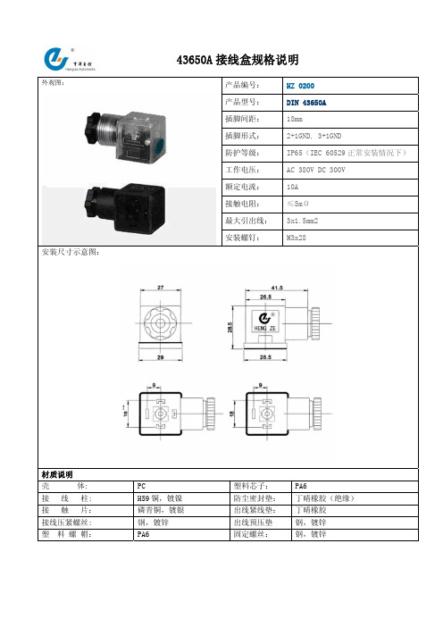
产品编号: HZ 0200 产品型号: DIN 43650A 插脚间距: 18mm
插脚形式: 2+1GND, 3+1GND
防护等级: IP65(IEC 60529正常安装情况下) 工作电压: AC 380V DC 300V 额定电流: 10A 接触电阻: ≤5mΩ 最大引出线: 3x1.5mm2 外观图:
安装螺钉:
M3x28
安装尺寸示意图:
材质说明 壳 体: PC
塑料芯子: PA6
接 线 柱: H59铜,镀镍 防尘密封垫: 丁晴橡胶(绝缘) 接 触 片: 磷青铜,镀银 出线紧线垫: 丁晴橡胶 接线压紧螺丝: 钢,镀锌 出线预压垫 钢,镀锌 塑 料 螺 帽:
PA6
固定螺丝:
钢,镀锌
43650A 接线盒底座规格说明
产品编号: HZ 0200B 产品型号: DIN 43650A-B 插脚间距: 18mm 插脚形式: 3+1GND
防护等级: IP65(IEC 60529正常安装情况下) 工作电压: AC 250V DC 300V 额定电流: 10A 接触电阻: ≤5mΩ 外观图:
安装螺钉:
M3
安装尺寸示意图:
材质说明 本 体: PA6
内 镶 件: H59铜 接 触 片: H59铜,镀锡。
电伴热厂家解析防爆电源接线盒如何接线
电伴热厂家解析防爆电源接线盒如何接线!
在人们日常生活中,尤其是冬季会出现管道冻结的现象,一般出现管道冻结的现象时用户都是采用电伴热系统进行管道防冻保温及抗凝,而购买电伴热系统后对于安装方面没有严格按照说明书进行安装,因此对使用寿命和性能方面造成一些偏差。
在购买电伴热系统后电伴热配件安装也很有讲究,如电伴热防爆电源接线盒在安装时内部就会有多股接线柱的选择,在接线时只需按照说明书安装即可,用户如果不放心可找电工或专业安装电伴热团队进行安装。
电伴热接线盒参数:
额定电压:交流220V/380V
额定电流:40A
电缆线嘴螺纹:G1/2
防爆标志:EⅡCT4
防护等级:IP54
橡胶电缆密封直径:11.7mm
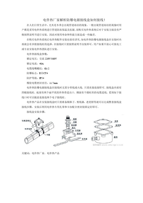
电伴热防爆电源接线盒在接线时无需分零线或火线,只需直接连接即可,接线盒内部有四根接线柱,底部有两个扁平状的伴热带进出口,侧面有个圆柱形的电缆进线,看到如下接线口时可以随意连接连两个电子接线柱。
电伴热产品在安装接线盒时只需准备铜鼻子,剪线器,老虎钳等就可以完成整套接线盒接线步骤,安装后利用电伴热专用扎带和卡扣配合密封胶固定好即可。
接线盒安装步骤:
关键词:电伴热厂家,电伴热产品。
浴霸怎么接线安装方法

浴霸怎么接线安装方法
浴霸是现代家居生活中常见的一种电器,它不仅可以提供照明,还可以起到加热和除湿的作用。
正确的接线安装方法对于浴霸的正
常使用和安全性非常重要。
下面,我们将介绍浴霸的接线安装方法,希望对大家有所帮助。
首先,接线安装之前,我们需要准备好相关的工具和材料,包
括螺丝刀、绝缘胶带、电线等。
在选择浴霸的安装位置时,需要考
虑到电源的位置和线路的走向,确保安装位置离水源和潮湿的地方
足够远,以免发生安全事故。
接下来,我们需要根据浴霸的使用说明书,找到浴霸的接线盒。
打开接线盒,我们可以看到里面有三根电源线,分别是火线、零线
和地线。
在接线之前,需要先关闭电源总闸,确保安全。
然后,根
据接线盒上的标识,将火线、零线和地线分别接到对应的位置上,
并用螺丝刀将接线端子拧紧,确保接触良好。
接下来,我们需要使用绝缘胶带将接线端子包裹好,以防止漏
电或短路。
接线结束后,需要再次检查一遍接线是否牢固,电源线
是否接错,确保没有安全隐患。
然后,可以将接线盒盖上,固定好,
并打开电源总闸,进行一次简单的功能测试,确保浴霸的照明、加热和除湿功能正常。
最后,需要注意的是,安装完成后,要定期检查浴霸的接线是否松动,是否有漏电现象,以确保浴霸的正常使用和安全性。
如果发现任何异常情况,应及时关闭电源,并请专业人员进行检修。
总的来说,浴霸的接线安装方法并不复杂,但是需要我们认真对待,确保每一步操作都正确无误。
只有正确安装,才能保证浴霸的正常使用和安全性。
希望以上内容对大家有所帮助,谢谢阅读!。
TB-68Pin屏蔽接线盒使用手册说明书
68Pin 屏蔽接线盒使用手册TB-68 User Manual Version: Revision Date:V1.1.0Feb 22, 2022目录1.快速上手 (1)1.1 缩写字说明 (1)2.规格 (2)2.1 电气规格 (2)2.2 Pin定义 (2)2.3 适配板卡列表 (3)3.操作指南 (4)3.1 使用温度转换模块 (4)3.1.1 使能温度转换模块 (4)3.1.2 温度转换关系 (5)3.1.3 温度转换模块适配板卡列表 (5)3.2 匹配5500系列数据采集模块 (6)3.2.1 匹配5510/5511板卡 (6)3.2.2 匹配5515/5516板卡 (7)4.关于简仪科技 (8)4.1 简仪科技中国 (8)4.2 简仪科技韩国和其它国家的简仪科技 (8)4.3 简仪科技硬件产品 (8)4.4 简仪科技的软件平台 (8)4.5 简仪科技服务 (9)5.声明 (10)1. 快速上手本章主要介绍如何使用本手册和快速入门。
1.1 缩写字说明AI:(Analog Input) 模拟输入AO:(Analog Input) 模拟输出DI:(Digital Input) 数字输入DO:(Digital Output) 数字输出PFI:(Programmable Function Interface) 功能可编程接口2. 规格2.1 电气规格2.2 Pin定义2.3 适配板卡列表3. 操作指南本章主要介绍TB-68产品的相关操作指南,主要包括温度转换模块、匹配5500系列板卡的使用方法等。
3.1 使用温度转换模块当用于支持TB-68温度转换模块的数据采集模块时,可以启用TB-68的温度转换模块以获取TB-68接线盒的温度状态。
TB-68温度转换模块启用时将在SCSI II接头Pin 68产生信号电压。
注意,启用温度转换时需要使用适配的数据采集模块进行电压测量,使用万用表等仪器无法在相应接线端子处测得目标电压。
BHG2高压电缆接线盒说明书
BHG2-630/10-2G说明书编辑使用范围本标准规定了供用户了解产品,正确搬运,安装,使用和维护的要求及内容。
BHG2-630/10-2G[1]执行标准接线盒执行GB3836.1~3-2000和MT/T946-2005《煤矿用增安型高压电缆接线盒》和Q/GD001-2008《矿用隔爆型高压电缆接线盒》标准。
概述接线盒适用于具有爆炸性气体(甲烷)和煤尘混合物的煤矿井下采煤掘进巷道中连接电力电缆电路接线之用。
可用于橡胶和铠装电缆。
产品型号含义防爆标志:“ExdI”爆型式:矿用隔爆型工作条件接线盒适于下列工作环境:海拔高度不超过1000m;环境气压(86~110)kpa;环境温度(—20~+40)℃;空气相对湿度不大于98%(+25℃时);具有甲烷煤尘爆炸性混合物的煤矿井下;无显著摇动和剧烈冲击振动的环境;在无破坏金属及绝缘的气体和蒸气的环境中;污染等级:3级;安装类别:Ⅲ类。
结构该接线盒是由壳体、盖和接线瓷座组成(见图1)。
用于防止电缆拔脱的压板设计成带有弧形沟槽的铸件,提高了压线的可靠性。
瓷座选用了性能优良高压电瓷粉烧制而成,具有较强的绝缘性能。
接线盒内部带电体之间的电气间隙,爬电距离均符合标准要求。
BHG1-200/10-2,BHG1-400/10-3(2) BHG1-400(315,200)/6-3(2)外形图主要参数接线盒的主要参数见表1。
表1型号额定电压(kV)额定电流(A)电器间隙(mm)爬电距离(mm)电缆外径(mm)控制线路额定电压控制线路额定电流BHG1-400(315,200)/6-3(2) 6 200,315,4060 80φ68~φ78127V 5ABHG1-200/10-2 10 200 100 125 φ68~φ78127V 5ABHG1-400/10-3(2) 10 400 100 125 φ68~φ78127V 5A外形尺寸及重量外形尺寸mm 重量kgBHG1-400(315,200)/6-2 856X552X220 60BHG1-400(315,200)/6-3 885X400X220 70BHG1-400(200)/10-2 906X420X256 70BHG1-400/10-3 876X562X256 80工频耐压电压等级kV 工频耐受电压kV7.2 2312 300.127 2注:工频耐压试验历时1min应无击穿和闪络现象。
QHJ系列接线盒 说明书
一、概述 由于传感器在出厂时,灵敏度及输出阻抗等参数不可能做到完全一致,再加上现场使用中的环境因素及安装方式的限制,给多个传感器并联组秤带来一定的偏载误差,当载荷位于秤上的不同位置时,可能造成称重仪表的显示不一致,我们把这种不一致称为“角差”。
为了解决上述问题,须选用接线盒,通过调整输出电压来使各传感器的灵敏度与输出阻抗之比接近一致。
新秤或使用时间较长的秤,尤其是使用了4个传感器以上的秤,如果偏载在3个分度值以上,单靠电位器的补偿是补偿不过来的,必须首先调整各支承点水平,确保偏载误差在3个分度范围内,再用电位器补偿调到基本一致。
这是一个反复的过程,调一个角可能影响到其它的角,只有反复调试直至平衡。
二、型号、命名及技术参数QHJ系列接线盒使用说明书型号192×130×40密封接头适合导线直径规格调节方式最大允许电压(V)材料外形尺寸(长×宽×高)(mm )与秤体安装尺寸(mm)正常工作温度(℃)储存环境温度(℃)防护等级QHJ-4QHJ-4A QHJ-6QHJ-8QHJ-10四线四线六线八线十线调信号18不锈钢318×160×64172×36(孔径Φ7)280×62(孔径Φ7)-10~50℃-20~60℃PG9(7~11mm)IP67三、技术概况1) 不锈钢或铝合金外壳,专用密封接头,耐用、密封性好。
2) 采用高精度、低漂移电阻和电位器,保证系统工作的精度和稳定性。
3) 传感器连线和信号电缆连线配用专用接线端子,保证连接可靠。
4) 各接线柱旁预留有可焊接线的焊孔,实现焊接接线和插入接线两用,可自主选择。
5) 接线焊接点旁注有代码标识,方便用户接线。
6) PCB 板焊有防浪涌及防感应雷的保护性元器件,可有效防止感应雷和浪涌信号对传感器及仪表的损坏。
四、安装、调试4.1 开箱检查请先检查一下包装内各部件是否完整。
包装盒内应包括下列部件: ● 接线盒 1只● 使用说明书 1份若缺少部件或部件损坏,请立即与本公司联系。
NI PXIe-4302 4303 和 RM-4302 用户指南及接线盒规范说明书
用户指南及接线盒规范NI PXIe-4302/4303和RM-4302NI PXIe-4302/4303、32通道、24位、滤波模拟输入模块、RM-4302支架安装接线盒本文档介绍如何安装、配置和设置带RM-4302支架安装接线盒的NI PXIe-4302和NI PXIe-4303 (NI PXIe-4302/4303)同步滤波模块。
NI-DAQmx 15.1.1最早提供对PXIe-4302/4303的驱动支持。
NI-DAQmx 15.5最早提供对RM-4302的驱动支持。
关于特定版本支持的设备列表,请参考具体版本下载页面或安装光盘中的NI-DAQmx自述文件。
注接线盒的定位设计可防止接入其他模块,避免接线盒上的电压对其造成损害。
但是,用户应该仅在接线盒上使用支持的模块。
目录电磁兼容性指南 (2)学习本教程之前的准备工作 (3)安装 (3)安装软件 (3)拆开产品包装并安装模块 (4)拆开产品包装,安装支架安装接线盒、机箱和线缆 (5)CAL IN (9)CAL BIAS (9)原位校准 (10)EXT PWR (10)电流故障保护重置 (11)资源 (11)RJ50 (12)LED状态指示灯 (12)PFI0 (13)开关 (13)确认SC Express模块识别 (14)运行测试面板 (15)进行NI-DAQmx测量 (15)NI-DAQmx通道和任务 (15)在MAX中使用DAQ助手配置任务 (15)在应用程序中使用SC Express设备 (16)编程范例 (16)2| |NI PXIe-4302/4303和RM-4302 用户指南及接线盒规范移除 (17)移除接线端盒和线缆.................................................................................................17移除模块....................................................................................................................17创建仿真设备....................................................................................................................18更多信息. (19)故障解答....................................................................................................................19产品规范(RM-4302) (19)电气............................................................................................................................19输入特性....................................................................................................................19外部电源 (EXT PWR)...............................................................................................20机械. (20)连接器.................................................................................................................20物理特性....................................................................................................................21环境. (21)运行环境.............................................................................................................21存储环境....................................................................................................................22冲击和振动.................................................................................................................22安全性........................................................................................................................22安全标准....................................................................................................................22电磁兼容性 (23)CE 规范......................................................................................................................23在线产品认证.............................................................................................................23环境保护....................................................................................................................23全球支持和服务.. (24)电磁兼容性指南经测试,产品符合电磁兼容性(EMC)要求和限制,详情见产品规范。
- 1、下载文档前请自行甄别文档内容的完整性,平台不提供额外的编辑、内容补充、找答案等附加服务。
- 2、"仅部分预览"的文档,不可在线预览部分如存在完整性等问题,可反馈申请退款(可完整预览的文档不适用该条件!)。
- 3、如文档侵犯您的权益,请联系客服反馈,我们会尽快为您处理(人工客服工作时间:9:00-18:30)。
传感器接线盒说明书
1、概述
由于传感器的关键材料:应变和弹性体各有差异及制造工艺方面的原因,造成各个传感器的参数不一致,主要是灵敏度不一致,通过调节接线盒里面的电位器来使各个传感器的灵敏度接近一致,从而保证整个称体的平衡。
CJ系列传感器接线盒就是调节大型衡器的重要配件。
2、型号命名方式:
C
J-------W------X------ Y------E
彩接接线盒调节形式
信线接线盒外型
电盒密封结头材料
子传感器的个数(2---12)
Y为原装德国进口密封结头G为国产结头
型对应不锈钢外壳,含连接头型对应不锈钢外壳,含连接头252*173*46,307*175*46,
4个固定孔尺寸:7mm。
4个固定孔尺寸:8mm。
型对应不锈钢外壳,含连接型对应进口ABS塑料壳
182*108*38,
4个固定孔尺寸:7mm。
178*111*35,4个固定孔尺寸: 4.5mm。
型对应透明外壳,含连接头C型对应不锈钢外壳,含连接头219*175*40,203*95*36,
4个固定孔尺寸:4.5mm。
4个固定孔尺寸:5mm。
E:为调桥压型号SJ:为调信号配精密电阻
SP:为调信号配普通电阻DL:为配数字式传感器
DA:为数字式线盒
3、调桥压的计算使用方法:(方便、快捷、省力)
大型电子衡器一般由多只传感器(1-12只)组成,下面以四只传感器组成的衡器为例,介绍计算调试方法。
调桥压接线盒原理图
图中J1、J2为四只传感器
N:为传感器上加载时的称重仪表显示数据(设:N1>N2>N3>N4)
E:称重仪表的供桥电压,I:为自然数:2—12
Ui:为W电位器二端的电压,W:为电位器,初始:0欧姆
Ui=[(N大-N小)/N小]*E*1000(mV)(以四个传感器为例)
U1=[(N1-N4)/N4]*E*1000(mV)
U2=[(N2-N4)/N4]*E*1000(mV)
U3=[(N3-N4)/N4]*E*1000(mV)
用三位半数字万用表DC-2V档,顺时针调节W1,W2,W3电位器,同时用数字万用表监视将电压到U1,U2,U3数值。
此时调角差工作全部完成。
例如:一台30吨的汽车衡,传感器的个数为4个,压角砝码为1吨,各压角的仪表显示值N1=1005,N2=1003,N3=1000,N4=998,称重仪表的供桥电压为5V。
则U1=[(1005-998)/998]*5*1000(mV)=35(mV)
U2=[(1003-998)/998]*5*1000(mV)=25(mV)
U3=[(1000-998)/998]*5*1000(mV)=10(mV) 顺时针调节(mV)W1,W2,W3电位器,同时用数字万用表监视电压到U1=35(mV),U2=25(mV),U3=10(mV)。
(调桥压的接线盒,公司出厂时电位器阻值一般为0欧姆,定货时可以注明将电位电调在中间)
4、参照内电路板的示意:
J0:对应连接到称重仪表,+E:接正供桥电源,
-E:接负供桥电源,+S:接正信号,
-S:接负信号,GND:接地。
切记:不能接错!!
上海彩信电子科技有限公司
地址:上海市金都路1128号5号楼3楼邮编:201108
E-mail:caisun@
电话:0086-21-54403572 54403576 传真:0086-21-54403549
技术服务热线(二十四小时昼夜服务):0086-21-64976650。