bmud30-c2说明书
全新i30 N 高性能汽車說明说明书

The All-New i30Photos for reference only圖片只供參考N. Born in Namyang.Honed at Nürburgring.The All-New i30 N marks the premiere of the new Hyundai N high performance range. N stands for Namyang, home of our global R&D centre. Born in Namyang and honed at the Nürburgring – the N logo also symbolises a racetrack’s chicane curve. Hyundai N cars are designed to perform – and to put a grin on your face. Engineered to satisfy drivers who want to feel the burst of adrenaline that gets your heart beating faster – The pure joy of driving.全新的 i 30 N 掀起一場屬於現代的高性能革命。
N 代表位於南陽的現代汽車研發中心,生於南陽長於紐布靈,賽車血脈融貫出彎曲賽道的標誌-N 。
N系車款在乎時速快感,更在乎駕駛樂趣。
啟動引擎,激發澎湃,一下貫穿全身。
N.Nothing but fun. 純粹.快樂。
Photos for reference only圖片只供參考 fun.Created for maximum driving fun on the road, the All-New i30 N has been meticulously engineered to get your heart pumping faster. Balancing racetrack driving dynamics and raw power with the possibility of comfort-oriented daily commuting, the i30 N is truly a sports car for every day – built to make every moment behind the wheel a chance for more kicks.全新 i30 N 以細致的機械美學撼動你心,駕駛之樂由此開創。
BIS-6390C30 整机说明书 用户手册

BIS-6390C30 整机说明书声明除列明随产品配置的配件外,本手册包含的内容并不代表本公司的承诺,本公司保留对此手册更改的权利,且不另行通知。
对于任何因安装、使用不当而导致的直接、间接、有意或无意的损坏及隐患概不负责。
订购产品前,请向经销商详细了解产品性能是否符合您的需求。
NORCO 是深圳华北工控股份有限公司的注册商标。
本手册所涉及到的其他商标,其所有权为相应的产品厂家所拥有。
本手册内容受版权保护,版权所有。
未经许可,不得以机械的、电子的或其它任何方式进行复制。
温馨提示1.产品使用前,务必仔细阅读产品说明书。
2.对未准备安装的板卡,应将其保存在防静电保护袋中。
3.在从包装袋中拿板卡前,应将手先置于接地金属物体上一会儿,以释放身体及手中的静电。
4.在拿板卡时,需佩戴静电保护手套,并且应该养成只触及其边缘部分的习惯。
5.主板与电源连接时,请确认电源电压。
6.为避免人体被电击或产品被损坏,在每次对主板、板卡进行拔插或重新配置时,须先关闭交流电源或将交流电源线从电源插座中拔掉。
7.在对板卡进行搬动前,先将交流电源线从电源插座中拔掉。
8.当您需连接或拔除任何设备前,须确定所有的电源线事先已被拔掉。
9.为避免频繁开关机对产品造成不必要的损伤,关机后,应至少等待30秒后再开机。
10.设备在使用过程中出现异常情况,请找专业人员处理。
11.此为A级产品,在生活环境中,该产品可能会造成无线电干扰。
在这种情况下,可能需要用户对其干扰采取切实可行的措施。
目录第一章产品介绍 (1)1.1 产品介绍 (1)1.2 硬件规格 (1)第二章安装说明 (2)2.1 右侧图 (4)2.2 左侧图 (4)2.3 前视图 (4)2.4 后视图 (5)第三章硬件功能 (3)3.1 外部接口指示图 (3)3.2 接口位置和尺寸图 (4)3.3 安装步骤 (4)3.4 跳线功能设置 (5)3.5 接口说明 (5)3.5.1 USB接口(USB1,USB2,TYPEC) (5)3.5.2 以太网接口(LAN) (6)3.5.3 TF接口(TF1,TF2) (7)3.5.4 SIM接口(SIM1,SIM2) (7)3.5.5 LED指示灯(LED2) (8)3.5.6 电源输入接口(DCJ) (8)3.5.7 接口(J3) (9)3.5.8 电池充放电接口(BAT) (10)3.5.9 复位按键(RESET) (11)3.5.10 开关机按键(PWRKEY) (11)第四章软件功能................................................................................................................. - 0 -4.1Linux系统............................................................................................................... - 0 -4.1.1 TF卡部分 .................................................................................................... - 0 -4.1.2 USB部分..................................................................................................... - 0 -4.1.3 COM部分.................................................................................................... - 0 -4.1.4 3/4G部分..................................................................................................... - 0 -4.1.5 以太网部分.................................................................................................. - 0 -4.1.6 其他 ............................................................................................................ - 1 -附录22附一:术语表 (22)装箱清单非常感谢您购买华北工控产品,在打开包装箱后请首先依据装箱清单检查配件,若发现物件有所损坏、或是有任何配件短缺的情况,请尽快与您的经销商联络。
正宗原版430说明书
雷霆、航科410/420/430是TVRO界的一个亮点,它们主板相同,但外接的卡座数量分别为1、2、3个,其中430(3卡座)可以解开三个加密系统,用遥控器可以随时切换,已成为普遍使用的机型,目前产地很多,但各种牌号430机器所配的说明书内容简单,对使用者帮助不大。
机器内的中文菜单虽说非常详尽,但欧洲式的菜单对于初次使用的人来说,还不是很容易掌握。
要过年了,瘦子抽空编个详细的说明书,作为给广大星友的节日礼物。
为避免有做广告之嫌,用XSA T430来表示所有牌号的430机器。
----这类机器的前面版基本都一样,后背板的接口也大同小异,但接口位置有所差异。
通常背板都配有电源开关,打开后机器处于待机状态,需要再按动面板上的电源键或遥控器上的电源键来进入工作状态。
用的较多的机器系统为南瓜系统和V+I双系统这种,通过按动遥控器上的Format键来转换不同的接收系统。
机器前后共三个卡座,后面的卡座为I系统使用,前面左右两个为N系统和V系统使用。
具体前面那个卡座是N系统用的,因厂家而异,试试就知道了。
初次使用该机器要注意,在南瓜系统下只能接收146、88、75等星上的加密节目,76.5、110.5等星上的加密节目是需要在V+I系统下设置接收的。
如果接收免费节目不受此限制。
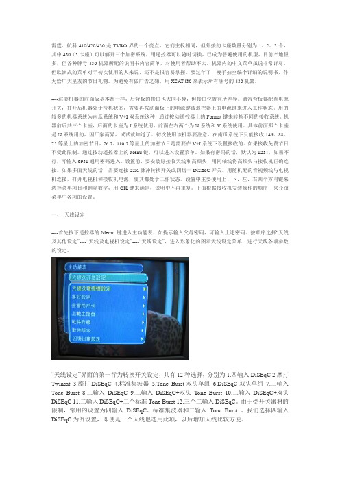
通过按动遥控器上的Menu键,可以进入设置菜单。
如果有密码的话,默认为1234。
如果不行,可输入6931通用密码进入。
设置前,要安装好接收天线和高频头,用同轴线将高频头与接收机正确连接。
如果多面天线的话,需要连接22K脉冲转换开关或四切一DiSEqC开关。
用随机配的音视频线与电视机连接,打开电视机和接收机电源,使其都处于工作状态。
设置中主要使用上、下、左、右四个方向键来选择菜单项目和删除数字,用OK键来确定,说明中不再重复。
下面根据接收机安装操作的顺序,来介绍菜单中各项的设置。
一、天线设定----首先按下遥控器的Memu键进入主功能表,如提示输入父母密码,可输入上述密码。
永大电梯故障TCD说明

○
◎
2/79 1/80
Rank 别 C1 A2
作成日期:99.02.05
Hold
○
STE-709-015
TCD 38 DSP 当机检出 TCD 39 100R ON/OFF 故障 TCD 40 ROTARY ENCODER 故障 TCD 41 低速 OVER SPEED TCD 42 50B OFF 故障 TCD 43 SPD 回路故障
内容
HOLD
作成日期:99.02.05
STE-709-015
11
A1
10T ON 故障
◎
检出目的
10T 主接触器应 OFF 而未 OFF 时,表示 10T 主接触器 ON 故障,电梯应立即紧急 停止,防止制御系统的信赖性低下。
检出条件
停层时,透过 MZ10T 出力 Buffer 控制 10T Ctt Turn OFF,并侦测 MX10T 及 SX10T 入力 Buffer 信号,来判定 10T Ctt 是否正常动作。 也就是当 MZ10T 出力 Buffer OFF,而 MX10T 及 SX10T 入力 Buffer 未在 500 ms 内 OFF,则检出异常。
3.10T主接触器状态Check: 10T主接触器卡住,接点曲折、熔着,配线短路等确认。
4.SMPU PCB与FIOR PCB之间排线;MUD及FOD Connect有无接触不良Check。
5.SFIOR PCB更换 第1项或第2项有状况,而第4项良好时,表示SFIOR出力Buffer不良,更换SFIOR PCB。
永大电梯 TCD 故障码一览表:
番号
内容表示
TCD 10 50B ON 故障 TCD 11 10T ON 故障 TCD 12 15B ON 故障 TCD 13 SDC 运转异常 TCD 14 从 MICON 当机 TCD 15 SDA 当机 TCD 16 主从并列通信异常
M30 C30 Proximity Sensor 商品说明说明书

Capacitive Cyclindrical Sensor M30 C30Proximity Sensor CatalogueCode CAT3SC31265101Technical Sheet – C30 - English - Ed. 01/20122/3ProductCylindricalcapacitativeSeriesC30CylindricalcapacitativesMarket Sectors And Applicationplastic industry chemical industry &petrochemistrywood industry photovoltaic installationsglass and ceramics industrylogistics packaging industry andautomatic storage systemsautomated hatcheries automaticvehicle washing systems swimmingpools and hot tubsvending machinesTechnical Characteristics DC or AC supply voltage AltaHigh noise immunityModel Flush And Not FlushAdjustable SensitivityPlastic Or Metal HousingCertificationProtection ClassIP674/5ProductCylindricalcapacitativecapacitive cylindrical sensor M30 C30The C30 capacitive proximity sensors are manufactured in a M30 polyester and metal screwhousing. Its high technological level allows to guarantee a high immunity to noise.A yellow LED indicates if the output is activated. The SCR output is normally closed or normallyopen. Models with 2 m cable or M12 connector are available. All sensors have the IP67 protectionclass.Package ContentInstruction manual (English)CAT8BCT1259401additional commercial and technical documentationData sheet (Italian CAT3ECQ3261649 and Spanish CAT3SCQ3261651) High resolution imagesApplication notes:- Position detection in buckets, dumpers and loaders in excavators (English CA-T3E001261620, ItalianCAT3I001261619 & Spanish CAT3S001261621)- Detection of food in automatic feeders (English CAT3E001261623, Italian CA- T3I001261622 & SpanishCAT3S001261624)- Water level detection in hydromassage pools (English CAT3E001261626, Italian CA- T3I001261625 &Spanish CAT3S001261627)- etection of the level of soap and wax in automatic washing systems (English CAT3E001261629, ItalianCAT3I001261628 & Spanish CAT3S001261630)- Water level detection in automatic washing systems (English CAT3E001261632, Italian CAT3I001261631 & Spanish CAT3S001261633)- Detection of merchandise in boxes (English CAT3001261635, Italian CATI001261634 & CastilianCAT3S001261636)- Detection of lyophilized products in vending machines (English CAT3E001261638, Italian CAT3I001261637 & Spanish CAT3S001261639)- Detection of presence and position in photovoltaic panels (English CAT3E001261641, ItalianCAT3I001261640 & Spanish CAT3S001261642)parameterized models already tested-minimum amount of order1 unitDescription of the codemodel disponibles6/7ProductosCylindricalcapacitativeTechnical specificationsmodelC30*/**-1*C30*/**-2*nominal range Sn16 mm25 mmdifferential travel H ≤ 20%repetition accuracy 5%Rated service voltage Ue 10 ... 40 Vdc o 20 ... 250 Vcamaximum ripple factor ≤ 10 % no load current ≤ 10 mApower with load ≤ 200 mA (Vcc models), ≤ 500 mA; max. 2.5 A max. 20 ms (Vca models)leakage current ≤ 10 µAvoltage drop in output 2,5 V máx. @ IL = 200 mA (model Vcc), ≤ 10 VCA @ IL ≥ 20 mA (model Vca)type of output NPN o PNP - NO o NC; SCR - NO o NC switching frequency s 50 Hz (dc models); 10 Hz (ca models)delay before availabilityelectrical protection power Polarity reversal, surge impulseselectrical protection outputs automatic reset short circuit, overvoltage (model Vcc)sensitivity adjustment yes Storage temperature -40 ... +85° Coperating temperature -25 ... + 80 ° C (without freezing)thermal drift ≤ 20 %EMC compatibility -According to directive CE 2004/108 / EC. Requirements according to EN 60947-5-2protection class IP67 (EN 60529) NEMA 1,3,4,6,13 LED indicators yellow (Lon / Don exit status) housing materialthermoplastic polyester, stainless steelmaterial of the active head polyesterweight30 g (M12) / 110 g (cable)M12 Model PNPModel NPNBN brown BU blue BK black WH whiteelectrical diagrams of connections1Bn+2 WhDouble Digital Output1 Bn~Double Digital Output3 Bu-2 BuDigital Output~dimensionesC30*/**-*E (cable outlet)C30*/**-*A (cable outlet)M12NA digital outputfeeding (-)4 312feeding (+)NC digital outputGroundingFeeding (~)Feeding (~)C30*/BN-**C30*/BP-** C30*/00-**ø 28Output by M12 connector, 4 pins, VccOutput by M12 connector, 3 pins, VcaLED Output by M12connectormm4 BkNONC3 Bu-1 Bn+NCNO2 Wh4 Bkø 28LEDCable outletVCA models with selectable NA / NC6213.615.412(*) 1012(*)5013.615.4Proximity SensorCatalogueCAT3SC31265101 TECHNICAL DATA SHEET C30 SPANISH ED.01 / 2012Any information provided in this catalog may be subject to modifications without prior notice and does not imply any liability on the part of M.D. Micro Detectors.All the modifications will be introduced in this catalog and its electronic version, available on the corresponding web page of M.D. Micro Detectors: 。
勾股定理例题含答案

勾股定理例题含答案COCa-COla StandardiZatiOn OfflCe [ZZ5AB-ZZSYT-ZZ2C-ZZ682T-ZZT18J勾股定理经典例题透析类型一:勾股定理的直接用法1、在RtΔABC 中,ZC二90°⑴已知 &二6, c=10,求 b, (2)已知 a=40, b=9,求 c;⑶已知 C二25, b=lo,求 a.思路点拨:写解的过程中,一定要先写上在哪个直角三角形中,注意勾股定理的变形使用。
解析:⑴ 在AABC 中,ZC二90° , a=6, c=10,2-a =8(2)在ZXABC 中,ZC二90° , a二40, b二9, c二丿盼 + 员=41(3)在AABC 中,ZC=90o , c=25, b=15,a=^2"^2 = 20举一反三【变式】如图Z^ZAC^O O , 3, CD=12y於3,则AB的长是多少?【答案]VZi46^=90° AD=13, CD=I2 AAC2 =AD2-CD2 =132-122=25ΛJO5又V ZABC=90° 且βc=3・•・由勾股定理可得AB⅛C2 -BC2=52-32二 16∙∖AB= 4AAB的长是4.BD = -AB = λ5= 30°, 2 ,再山勾股定理计算出川9、%的长,进而求出兀的长.解析:作丄EC于D则因= 60° ,Λ^D=90O-60O=30O (佥A的两个锐角互余)BD = -AB = A5 n λ••• 2 (在用△中,如果一个锐角等于30°,则有类型二:勾股定理的构造应用2、如图,已知:在中,Z-5 = 60o, ^C r = 70 T ^4-5=30.求恭的长.那么它所对的直角边等于斜边的一半)・ 根据勾股定理,在劭以他中, AD=JAB 2-BD 2=^j3(f-↑52 = ↑5^∣3 根据勾股定理,在矗MUD 中, CD = JQ 一肋2 = √702-152X 3 = 65∙∙∙ Sσ = SD + DC=65+15 = 80• • •举一反三【变式1】如图,已知:ZC = 9tr, AM = CM 9 MP 丄于* 求证: B^=AP 2 十衣C2乂 ••• AM = CM (已知),• • •在电AECM 中,根据勾股定理有BM 2-CM 2= SC ∖λ5Z D 2 = ^C 2+^2 • • • 【变式2】已知:如图,ZB=ZD=90o, ZA 二60° , AB=4, CD 二2。
SW600动物重量计操作手册说明书
SW600Operators ManualHelloFt. Atkinson, Wisconsin USADigi-Star InternationalPanningen, The NetherlandsD3656-US Rev E August 14, 2014SW600 TABLE OF CONTENTSCHARGING BATTERY OR WELDING (3)INDICATOR OVERVIEW (4)BOTTOM PANEL (5)OPERATION (6)TURNING ON THE SCALE (6)ZERO BALANCING (6)WEIGHING ANIMALS (6)SELF TEST (7)OPTIONAL SETTINGS (7)CHANGE SETUP FOR LOAD CELLS. (7)DETERMINING THE NEW CAL NUMBERS (8)CHANGE OPTIONS (USING LONG FORM SETUP) (9)WEIGH METHODS (12)GENERAL WEIGH METHOD (12)SLOW WEIGH METHOD (12)FAST WEIGH METHOD (12)LOCK-ON WEIGH METHOD (12)WEIGHING ERRORS (13)STOCKWEIGH LOAD CELLS (14)STOCKWEIGH LOAD CELL SPECIFICATIONS (14)LOAD CELL DIMENSIONS (15)SCOREBOARD METHODS (17)PRINT FORMATS (18)TROUBLESHOOTING GUIDE (20)INSTALLATION (23)INDICATOR MOUNTING (23)OPTIONAL RAM MOUNTING (23)LOAD CELL CONNECTION (24)D3656-US-SW600 Operators-Rev E SCCAll rights reserved. Reproduction of any part of this manual in any form whatsoever without Digi-Star’s express written permission is forbidden. The contents of this manual are subject to change without notice. All efforts have been made to assure the accuracy of the contents of this manual. However, should any errors be detected, Digi-Star would greatly appreciate being informed of them. The above notwithstanding, Digi-Star can assume no responsibility for errors in this manual or their consequence.© Copyright 2014 Digi-Star, Fort Atkinson (U.S.A.).2 D3656Operators ManualCHARGING BATTERY OR WELDINGImportant: Disconnect all indicator leads before charging battery or welding equipment. Damage may occur to indicator and load cells.D3656 3SW600INDICATOR OVERVIEW- press and hold to zero balance.- reweigh if scale is locked on. - press and hold for setup menu.- turns indicator on/off.123412344 D3656Operators ManualBOTTOM PANELSerial/Printer – Port used to communicate with computer and otherdigital input/output devices such as a printer.Power – Port for Power Cord. Load Cell – Port for load cell cord. Load Cell – Port for load cell cord.56785678D3656 5SW600OPERATIONTURNING ON THE SCALEZERO BALANCINGWEIGHING ANIMALS1. Press .1. Press and hold to zero balance.1. Place animal on platform. Indicator “Locks On” animal’sweight, “L” appears in upper left of display. 2. Release animal.HELLO1L 6D3656Operators ManualSELF TEST1. Press and within three seconds press to start self test.2. Press to exit test (except during key test).OPTIONAL SETTINGSCHANGE SETUP FOR LOAD CELLS.1. Press and hold andfor long form setup menu. 2. Press to advance through selections 3. Press to set.3300LB StockWeigh 3300 (pounds) 6600LB StockWeigh 6600 (pounds) 10K LB StockWeigh 10000 (pounds) 14K LB StockWeigh 14000 (pounds) 3300KG StockWeigh 3300 (kilograms) 6600KG StockWeigh 6600 (kilograms) 10K KG StockWeigh 10000 (kilograms) 14K KG StockWeigh 14000 (kilograms) CustomAny other load cell.D3656 7SW600DETERMINING THE NEW CAL NUMBERS1. P ress and hold to zero balance the scale.2. P lace a known weight on the scale (Example: 1000 LB test weight). Perform the following calculation to find the new calibration number:3. Press and hold and to enter setup menu.4. Press to select Custom (see page 7).5. Press indicator will display SETUP followed by the setup number.6. Setup number does not change.7. Press to advance to “Cal”.8. Enter the new CAL # by pressing to change the value of "flashing" digit and to select which digit of display is flashing.9. Press to store new calibration number.13578928 D3656Operators ManualCHANGE OPTIONS (USING LONG FORM SETUP)To modify options in following chart:1. P ress and hold .2. Press to change setting.3. Press to save setting and advance to next menu item.4. Press to return to weighing mode.Setting/ Display Options(Bold=Default)DescriptionMENU 1Language (LANGAG)English (ENGLSH)Dutch (NEDERL)French (FRANCS)German (DEUTSH)Italian (ITAL)Portuguese (PORT)Spanish (ESPAN)Danish (DANSK)Hungarian(MAGYAR)Spanish (VESTA)Select language to be displayed.Zero Tracking (ZTRACK)ON/OFF Zero track adjusts to zero forbuild-up of snow and mud. If"ON", the scale will adjust forsmall weight variances (+/- 5lbs)in the Lock-On weigh method.Weigh Method (W MTHD)1, 2, 3, 4 Select weigh method. See page12.Lock-On (LOCKON)1-7 , 8, 9 Use the lowest setting that stillallows the system to lock onconsistently. A low value allowsthe system to be more sensitiveto animal motion. A high valueallows the scale to lock on faster.Lock-N-Hold (LKNHLD)On/OFF Weight is held until next animal isweighed.D3656 9SW600Setting/ DisplayOptions (Bold = Default) DescriptionAuto Off (AUTOFF ) 15, 30, 45, 60, OFF Indicator automatically shut OFF after specified time of inactivity. Lock-On Store (LSTORE )OFFAUTOWTMANPRTSends data to computer port only when TAREAP or APRINT are set to “ON”.Automatic WeightSends time, date and weight data to computer port when the scale “Locks-On” or when the animal steps off platform.Sends time, date and weight data to the computer port when operator presses .Lock-On Store (LSTORE )AUTOPRTMANWTSends Time, Date and Weight data to the computer port when the scale locks-on or when the animal steps off the platform. -Sends time, date and weight data to the computer port when operator presses .Lock-On-Store Send (LSSEND )ON/OFFLSSEND is for LSTOREautomatic modes and has no effect in manual modes.If set to “OFF”, data is sent when animal steps off the platform. If set to “ON”, data is sent as soon as the scale locks-on.If set to “ON”, press torecheck the weight and send new data to computer port.10D3656Setting/ Display Options(Bold =Default)DescriptionOne Line Print (1LPRINT)On/OFF ON formats printer output data onone line.OFF formats printer output data intwo lines.Scoreboard Mode (SCOREM)1,2,3,4,5,6, Methods to continuously outputdisplay data to a scoreboard viathe com port. See page 17.Auto Print(APRINT)On/OFF Weight value printed automatically.Com In (Com In)DOWNLD,EZ CMD, EZ2CMDCom port interface selectionsDOWNLD for Data Down Loader,EZ CMD = Original EZCommands, EZ2CMD = EZIIEscape Commands.Print Format (PRTFMT)AUTO, WTONLY,DOWNLD, DT+TM,ID+TM, IDWTTM,ANIMALSee page 18.Com 1 Delay (C1 DLY)OFF, .10, .25, .50, .75,1-5Choose the number of seconds theprinter will delay before advancingto the next print line.Com 2 Delay(C2 DLY)Not Used.Display Count (COUNT).01,.02,.05,.1,.2,.5,1,2,5,10,20, 50,100Indicator display count. If thecounts are too small, the readingwill show more instability.Auto-Range (ARANGE)ON/off Increases display count size forweights over 300 and again at 600lbs/kgs.Display Unit(LB-KG)LB/kg Display units.Capacity (CAP)4000Enter MAXIMUM weightmeasurable on scale.WEIGH METHODSSelect weigh method #4 for animal weighing. When weighing dead loads, you can still use the Lock-On Weigh method but you may wish to use one of the other methods listed below.GENERAL WEIGH METHODAll-purpose weigh method for weighing dead loads. It is used for most applications.SLOW WEIGH METHODAttempts to provide higher accuracy by filtering many weight samples over a longer period. Use for weighing dead loads.FAST WEIGH METHODThe Fast weigh method is more sensitive to weight changes than the other weigh methods. When a weight changes quickly, the Fast method tries to determine the new weight as quickly as possible. This method is for weighing dead loads.LOCK-ON WEIGH METHODWeighs active animals and displays stable accurate weight. Lock-On sensitivity adjusted using “LOCKON” menu.•Once actual weight is displayed, scale “Locks-On” to weight.•Weight is displayed stable, even if motion never stops.•Small ‘L’ appears on left side of display indicating weight “Locked-On.”•Animal’s weight must be greater than 0.67% of scales “capacity”weight before system can “Lock-On.”Note: Customers should use a weight value for Zero Tracking (ZTRACK) that is less than 0.67% of capacity.To break lock, add or remove preset percentage of displayed weight. The default setting is 50%.•The weight value that is used to “break the lock” and return to normal weighing can be selected by choosing a value from 01 to99%. For example, if unlock is set to 10(%) and weight is locked at1000, display will “unlock” and return to normal weighing at 900,once 10% (100) is removed.•“Locked-On” weight can be “rechecked”, pressing . breaks “lock” and scale recalculates weight.OVRCAP Over Capacity LimitThe display shows the message “OVRCAP” if the weight on scale system exceeds capacity limit.+RANGE Over Range –The display shows message "+RANGE" if weight on the scale system is less than the maximum weight measurable by scale system.-RANGE Under RangeThe display shows message "-RANGE" if the weight on the scale system is less than the minimum weight measurable by the scale system.LO BAT Low Battery IndicationIf the supply voltage drops below the (10.5 Volts), the message‘RECHARGE BATTERY – TURNING OFF” and “LO BAT” will periodically show on the display to alert the operator of the low batterycondition.Warning!STOCKWEIGH LOAD CELLSLoad Cells with Connectors:Load Cells without Connectors:STOCKWEIGH LOAD CELL SPECIFICATIONSModel 3300 Model 6600 Length 16” 24” 33-1/2”33-1/2” 44” Part Number 148042 146769 400144400058 400006Model 3300 Model 6600 Length 16” 24” 33-1/2”33-1/2” 44” Part Number 403481 403482 403483403484 403485Model 14,000 Part Number 400161LOAD CELL DIMENSIONS Model 3300Model 6600StockWeigh Alley PlatformPN 403360120 Volt AC/12 Volt DC Power ConverterPN 403526SCOREBOARD METHODS Scoreboard methods 1 through 6 are used for the Stock Weigh 600. Many other scoreboard methods are available but are not used.1. Transmit numeric display data once per second.2. Transmit numeric display data two times per second.3. Transmit numeric display data three times per second.4. Transmit numeric display data at the A-D conversion rate.5. Transmit numeric display data at the display rate.6. Transmit numeric display data whenever there is a display weightchange.NOTES: When using SCOREM = 1, 2, 3, 4, 5 and 6 be sure to set LSTORE = OFF, TAREAP = OFF and APRINT = OFF to avoidcorrupted data when transmitting scoreboard data and printingscale data.With COM IN set to EZ2CMD the port configuration is: 9600Baud, 1 start bit, 7 data bits, 1 even parity bit and 1 stop bit.With COM IN set to EZCMD the port configuration is:1200Baud, 1 start bit, 7 data bits, 1 even parity bit and 1 stop bit.PRINT FORMATSPRTFMT is active when “LSTORE” is set to “OFF”, “MANPRT” or “AUTPRT”. Following is a detailed explanation of the print formats that are available on the StockWeigh 600. Some are Comma Separated Values (CSV) that make it easier to input scale data into PC Spreadsheet and Data Base programs. NOTE:The appearance of the printouts may be affected by the option settings of 1L PRT, TIME F and DATE F.AUTO If “LSTORE” is set to “MANPRT” or “AUTPRT” and“PRTFMT” is set to “AUTO”, the standard EZ Indicator printformat will be used.Print example:09MR04 10:15880LB$GRWTONLY Includes weight, display unit, $' if unit is "locked on", weight tag (GR, M+, etc.).Ends with a <CR>,<LF>. Print example:635LB$GRDOWNLD This format is compatible with the original Downloader.Includes weight, display unit, $'if unit is "locked on", weighttag (GR, M+, etc.) date and time.DT+TM This CSV format includes weight, display unit, $'if unit is"locked on", weight tag (GR, M+, etc...) and date.Ends with a <CR>,<LF>.Print example:" 610,LB, ,GR,13MR02,11:08"ID+TM This CSV format includes ID, weight, display unit, $'if unit is "locked on", weight tag (GR, M+, etc...) and time.Ends with a <CR>,<LF>.Print example:" , 0,LB, ,GR,11:08"IDWTTM This CSV format includes ID, weight, display unit, $'if unit is "locked on", weight tag (GR, M+, etc...), date and time.Ends with a <CR>,<LF>.Print example:"FARM 1, 16090,LB, ,GR,27JA00,10:37P"ANIMAL This CSV format includes information for animal weighing.Includes $'if unit is "locked-on" weight, weight tag (GR, M+,etc...), display unit, Memory Weight (RM), Average Count(Number of times M+ key was pressed), Average Weight,Gross weight on scale, ID, date and time.Ends with a <CR>,<LF>.Print example:" , 1400,GR,LB, 2180, 4, 545,1400, ,11:09,13MR02"TROUBLESHOOTING GUIDEIndicator Does Not Respond When You Step on the ScaleThe Scale Weighs Close to Your WeightINSTALLATIONIndicator MountingRAIL MOUNT WING MOUNTWEDGE MOUNT STANDARDKEY PART NUMBER DESCRIPTIONA 403769 BRACKET – STR TOP MOUNTB 403980 BRACKET – ROBO MOUNTINGC 403770 BRACKET – WING MOUNTD 405069 U-BOLT, 1/4-20 X 3.25 ZPE 403771 MODIFIED PLASTIC WEDGE MOUNTF 405124 WEDGE MOUNT BRACKET, INCLUDES U-BOLTS & NUTSG 405084 NUT, 1/4-20 TOP LOCKING FLANGEOptional Ram MountingRAM MOUNT STANDARD U-BOLT BASE TWIST LOCK SUCTION CUP KEY PART NUMBER DESCRIPTION A 403180 RAM MOUNT B 403179 MOUNT BASE-1" BALL U-BOLT C 404230 RAM SUCTION CUP W/TWIST LOCKLOAD CELL CONNECTIONblocks. See Wire ColorKeyJ-Box Illustratedfor 4 Load Cell InstallationConnect to Indicator bottom panel.Load cell cable。
MD30C 30A DC Motor Driver User's Manual
MD30C30A DC Motor DriverUser's ManualV1.4December 2017Index1.Introduction 32.Packing List 43.Product Specification and Limitations 54.Board Layout 65.Dimension86.Hardware Installation97.Warranty16MD30C is the successor of MD30B which is designed to drive medium to high power DC Brushed motor with current capacity up to80A peak and30A continuously.Fully NMOS design not only provides faster switching time,it is also more efficient and no heatsink or fan is required.Besides,MD30C also incorporates some user friendly features such as reverse polarity protection and onboard PWM generator which allows it to operate without a host controller. The motor can simply be controlled with the onboard switches and speed potentiometer. External switches and potentiometer can also be used.Features:●Bi-directional control for 1 brushed DC motor.●Motor V oltage: 5V - 25V 30V.●Maximum Current: 80A peak (1 second), 30A continuously.●Reverse polarity protection.● 3.3V and 5V logic level input.●Fully NMOS H-Bridge for better efficiency and no heatsink is required.●Speed control PWM frequency up to20KHz(Actual output frequency is same asinput frequency when external PWM is selected).●Onboard PWM generator with switches and potentiometer for standalone operation.●Support both locked-antiphase and sign-magnitude for external PWM operation.MD30C is now Revision 2.0.Please check the parts and components according to the packing lists. If there are any parts missing, please contact us at s***************.my immediately.1. 1 x M D30C 30A DC Motor Driver2. 2 x M ini Jumper3. 1 x 2510 PCB Connector - 3 Ways (Female)4. 3 x 2510 Terminal Pin3.0 PRODUCT SPECIFICATION AND LIMITATIONSAbsolute Maximum RatingParameter Min Typical Max Unit Power Input V oltage (Motor supply voltage) 5 - 30 V I M AX (Maximum Continuous Motor Current)- - 30 A I P EAK (Peak Motor Current)* - - 80 A I I DLE (Idle Current) - - 100 mA V I OH (Logic Input-High Level) 3 - 5.5 V V I OL (Logic Input - Low Level) 0 - 0.5 V Maximum PWM Frequency** - - 20 KHz *Must not exceed 1 second.**Actual output frequency is same as input frequency when external PWM is selected.4.0 BOARD LAYOUT1.Power Terminal BlockConnect to power source.For high current application,please solder the wire directly to the pad at bottom layer.2.InputPin No. Pin Name Description1 GND Ground2 PWM * P WM input for speed control.3 DIR Direction Input.* N ote this is not RC (Radio Control) PWM3.PWM Source SelectorSelect the source of the speed control PWM.PWM Source JP4 JP6Internal Potentiometer INT POT INT PWMExternal Potentiometer EXT POT INT PWMExternal PWM Signal X (Don’t Care) EXT PWM4. I nternal PWM PotentiometerUsed to control the motor speed when PWM source is internal potentiometer.5.External PWM Potentiometer PortConnect to the external potentiometer(10K Ohm) .Used to control the motor speed when PWM source is external potentiometer.6.Test Button AWhen this button is pressed,current flows from output A to B and motor will turn CW(or CCW depending on the connection).External switch can also be connected for the ease of access.7.Test Button BWhen this button is pressed,current flows from output B to A and motor will turn CCW (or CW depending on the connection).External switch can also be connected for the ease of access.8.Motor Terminal BlockConnect to motor.For high current application,please solder the wire directly to the pad at bottom layer.9.Red LED A.Turns ON when the output B is low and output A is high.Indicates the current flows from output A to B.10.Red LED BTurns ON when the output A is low and output B is high.Indicates the current flows from output B to A.11.Green Power LEDTurn on when the MD30C is powered up.Created by Cytron Technologies Sdn. Bhd. – All Right Reserved75.0 DIMENSION6.0 HARDWARE INSTALLATION AND GETTING STARTED6.1 Power and Motor ConnectionWe recommend to use battery as power source to MD30C.The battery and motor can be connected to the M D30C either via the screw terminal block,or it can be soldered directly to the pad at the bottom layer of the PCB.Make sure the battery and motor are connected to the correct port.Connecting battery to the motor port will burn the MOSFETs on MD30C and this is not covered under warranty.NOTE:For application where the current is>20A,it’s recommended to solder the wire directly to the pad at bottom layer.Battery is connected to MD30C via terminal blockNOTE:If Switching Power Supply is being used as power source for MD30C,we recommend parallel it with same voltage battery.This is to absorb the re-gen power from motor.DC brushed motor will become generator when it is slow down and rotate by external force.Motor is connected to MD30C via terminal blockBattery is soldered directly to MD30CMotor is soldered directly to MD30C6.2 Standalone OperationThe M D30C can operate in standalone mode.In this mode,the motor is controlled by the onboard switches and speed potentiometer.Alternatively,external switches and potentiometer can be used to control the motor.This allow the switches and potentiometer to be mounted at easy to reach place.Onboard Switches and PotentiometerSet the jumpers as below:JP4 : INT POTJP6 : INT PWMAfter that,connect the battery and motor to the MD30C.Pressing switch A will run the motor in CW direction and pressing switch B will run the motor in CCW direction(The actual direction is depending on the motor polarity).The speed of the motor can be controlled by the onboard speed potentiometer.Don’t worry if the motor does not run when the switch is pressed.This might be due to the speed is too low for the motor to run.Try turning the on board potentiometer CW(clock wise) for a few round while pressing down one of the switch to increase the motor speed.External Switches and PotentiometerSet the jumpers as below:JP4 : EXT POTJP6 : INT PWMConnect the external switches and potentiometer as below.Please note that the onboard potentiometer will have no effect when JP4is changed to EXT POT.The recommended resistance for external potentiometer is 10K Ohm .Created by Cytron Technologies Sdn. Bhd. – All Right Reserved13External potentiometer is connected on JP5. Please use potentiometer or Variable Resistor with value of 10K Ohm . It can be direct solder, just make sure the pads are clean from fluxor any solder ball.External switch is connected to JP7 and JP86.3 Interface with MicrocontrollerTo control the motor with a microcontroller, set the jumpers as below:JP4 : Don’t CareJP6 : EXT PWMTruth table for the control logic:PWM DIR Output A Output BLow X (Don’t Care) Low LowHigh Low High LowHigh High Low High**Please do note that to set either DIR or PWM pin at LOW condition first when power is on.Picture below shows an example of connecting the M D30C to the S K40C .7.0 WARRANTY●Product warranty is valid for 6 months.●Warranty only applies to manufacturing defect.●Damaged caused by misuse is not covered under warranty●Warranty does not cover freight cost for both ways.Prepared byCytron Technologies Sdn. Bhd.No. 1, Lorong Industri Impian 1,Taman Industri Impian,14000 Bukit Mertajam,Penang, Malaysia.Tel: +604 - 548 0668Fax: +604 - 548 0669URL: www.cytron.ioEmail: s*******************************。
上海永大电梯-新故障码解说解读
U V W制櫃入電子台馬達源端台版次 1.1TCD 故障等级内容HOLD54 A1 RE故障(U,V,W相磁极角度异常) ◎检出目的在PM马达控制中,变频控制器,利用编码器(ENCODER)uvw信号,来判断PM马达磁极所在位置,进一步送出正确的三相电压以产生一旋转磁场。
若编码器中任意一相以上损坏,将导致控制器送出的旋转磁场无法与马达磁极位置吻合,而造成马达运转不顺畅,让电梯产生晃动,此时应立即时停机。
检出条件1.Rotary Encoder的磁极检出Plus全部为HI,且持续检出1.37ms以上,则立即停止运转,且不可再起动。
2.Rotary Encoder的磁极检出Plus全部为LO,且持续检出1.37ms以上,则立即停止运转,且不可再起动。
注1.13. Rotary Encoder编码顺序不正常,且持续检出1.37ms以上,则立即停止运转,且不可再起动。
复归方式故障排除,FFB切OFF-ON后,操作MODE 2清除TCD,方能恢复运转。
调查项目:1.检查uvw之LED灯号是否正常。
2.检查ENCODER有无损坏〈下图〉,若损坏请更换ENCODER,若无请检查第二项。
观看编码器是否波型正常量测讯号版次 1.13.检查U79 (AM26LS32AC) 有无损坏〈下图〉U79 (AM26LS32AC)版次1.1TCD 故障等级 内 容 HOLD 55 A1马达电流检出回路异常◎检出目的本故障的检出目的及条件分为以下三种:1、避免HCT 长久使用损坏或Switching Power 之5V 电压异常下,使零点偏移(亦及电流为零时DSP 输入信号电压不为2.5V 与DSP A/D 参考电压不为5V)。
此时CPU 读入电流回授信号将不正确,而造成马达运转不顺畅,让电梯产生晃动,此时电梯不应再次走行。
2、避免HCT 长久使用损坏或Switching Power 之P15V 电压异常下,而造成IPM 烧毁。
HM A30 说明书
Hotline:1300 418 640Monday/Friday: 9.00am to 4.30pm Saturday: 9.00am to 3.00pm Email:************************.au Model HM A30IMPORTANT:Read instruction manual carefully before use. Keep for future referenceDESCRIPTION OF PRODUCT PARTS 1TECHNICAL SPECIFICATIONS 2INTENDED USE 2SAFETY INFORMATION 2ASSEMBLY 4OPERATION67TROUBLESHOOTING 8WARRANTY9HM A30 Instruction ManualCLEANING, MAINTENANCE AND STORAGE DISPOSAL8As shown in Fig. 11.Upper handle2.Handle extension3.Lower handle4.Blade guard5.Wheels6.Height adjustment lock7.Grass collection catcher8.Grass collection catcher strapWARNING: If any parts are damaged or missing, please contact Action Spares 1300 418 640. Do not operate this mower until the parts arereplaced.TECHNICAL SPECIFICATIONSModelHM A30Cutting Width300 mm Grass Catcher Capacity 20 L Net Weight 6.5 kg Cutting Height15-42 mmINTENDED USEThis hand push mower is designed for lawn mowing. It is for domestic use only, not for commercial, trade or industrial use.Description of SymbolsSymbols are used in this manual to attract your attention to possible risks. These safety symbols and their explanations must be fully understood. The warning themselves do not prevent the risks and can not be a substitute for proper methods of avoiding accidents.SAFETY INFOTMATION2dagfccbhieja.Hand mower (ready-assembled)b.Upper handlec.Handle extension (2x)d.Lower handle Ae.Lower handle BScope of deliveryf.Grass collection catcher frameg.Grass collection catcher bagh.Screw M6 x 30 (4x)i.Screw M6 x 25 (4x)j.Hex nut M6 (8x)1.2.3.4.5.6.7.8.9.10.11.12.13.14.Read instruction manual carefully before use this mower.Never allow children or people unfamiliar with the instruction manual to use the mower.Never mow while people, especially children or pets are nearby.Keep in mind that the operator or user is responsible for accidents or hazards occurringto other people or their property.While mowing, always wear safety footwear and long trousers. Do not operate themower when barefoot, or wearing open sandals.Thoroughly inspect the area where the mower is to be used and remove all objectswhich can be thrown by the mower.Mow only in daylight or in good artificial light.Avoid mowing in wet grass.Always be sure of your footing on slopes.Walk, never run.Do not mow excessively steel slopes.Do not put hands or feet near or under rotating parts.Keep all nuts, bolts and screws tight to be sure the mower is in safe working condition.Replace worn or damaged parts for safety.Safety instructionsRisk of injury from the cutting blades. Keep hands and feet clear.Do not open or remove safety shields while using the mower Debris can be thrown by the cutting bladesKeep bystanders awayWARNING!WARNING! Read instruction manualWarning symbolsDispose of mower according to the regulation and requirement of local councilStay alert, watch what you are doing and use common sense when operating thismower. Do not use this mower while you are tired or under the influence of drugs, alcohol or medication. A moment of inattention while operating this mower may result in serious personal injury.Assembling the handle (Fig. 2-3)Fig. 2Fig. 31.Insert the handle extensions (c ) into the upper handle (b). Fasten the handle extensions (c)and upper handle (b) together using two screws (i) and nuts (j).2.Join the two lower handle sections (d and e) together using two screws (i) and nuts (j).3.Join the handle extensions (c) and lower handle (3) together using four screws (h) and nuts (j).4.Locate the two metal lugs (9) on the mower. Insert the large hole in the lower handle over the lug, then repeat the same process on the other side. It may be necessary to squeeze the two lower handle arms together for mounting the other side.Assembling the grass collection catcher (Fig. 4-6)1.Insert the grass collection catcher frame (f) onto the metal frame (10) of the grass collection catcher bag (g).2.Fix the grass collection catcher frame (f) to the grass collection catcher bag (g) with the plastic clips (11) on the grass collection catcher bag (g).15.dAttaching the grass collection catcher to the mower(Fig. 7-8)1.Insert the hook (13) of the grass collection catcher frame (f) to the slots (14).e the strap (8) to tie the grass collection catcher to the lower handle (4)Fig. 7Fig. 8Adjusting the cutting heightNOTE The support roller (15) must be parallel to the lower cutting blade (18).Fig. 91.Loosen the height adjustment locks (6) on both sides of the mower.2.Move the support roller (15) to different height level as desired.3.Re-tighten the height adjustment locks (6) and make sure the support roller (15) is secured in position.Fig. 10MowingWARNING ! Check and make sure the handle is assembled and installed properly and there is no damaged part before mowing.Push the mower at steady pace. The rotation of the wheels turns the blades.The mower is hard to push when the grass is too tall. It is recommended to mower the lawn regularly1.2.WARNING ! Blades are sharp, always wear protective gloves when cleaning and maintenance of the mowerCleaning1.Remove the grass from the grass collection catcher after mowing.e a brush and plastic scraper (if required) to remove the grass on the mower.3.Wipe the mower with a damp cloth to remove the dirt.4.Never use water or high pressure water jet to clean the mower.Maintenance1.Keep all nuts and bolts tight to ensure the mower is in a safe working condition.2.Replace worn or damage parts if necessary.3.Be careful during adjustments of the mower to prevent entrapment of the fingers between the moving blade and the mower.Adjusting the lower cutting blade to the blades (Fig. 10)The lower cutting blade (18) should be as close to the blades (17) as possible, when the blades (17) are rotated manually, they should make slight contact with the lower cutting blade.If the contact between the blades (17) and lower cutting blade (18) is too loose, the cutting is rough and uneven.If the contact between the blades (17) and lower cutting blade (18) is too tight, the mower will be difficult to push and noisy.The lower cutting blade (18) is pre-set at the factory. However, it may need to be adjusted after using for a period of time.Turn the adjustment nuts (16) on both sides clockwise to move the lower cutting blade (18) towards the blades (17).Turn the adjustment nuts (16) on both sides anti-clockwise to move the lower cutting blade (18) away from the blades (17).1.2.3.4.5.6.Turn the mower upside down.Hold a piece of paper between the lower blade (18) and the blades (1 ).Turn the blades carefully by hand, all the blades should cut the paper evenly along the entire length of the lower blade (18) and the CMBEFT can turn freely.1.2.3.Cutting testStorage1.Clean the mower before storage.2.Grease the blades lightly if the mower is not be used for a long period of time.3.Store the mower in a dry place, out of reach of children.Dispose of the mower according to the regulations and requirements of your local council.9WARRANTYThis product is covered by a 1 year parts and labour warrant against manufacturing defects.Our goods come with guarantees that cannot be excluded under the Australian Consumer Law.You are entitled to a replacement or refund for a major failure and for compensation for any other reasonably foreseeable loss or damage. You are also entitled to have the goods repaired or replaced if the goods fail to be of acceptable quality and the failure does not amount to a major failure.This warranty will not apply:In order to obtain warranty service, the purchaser must present the store receipt showing the name of the retailer and the date of purchase.The period of the warranty begins from the original date of purchase, notwithstanding any subsequent repair or parts replacement.Purchaser shall be responsible for all transport charges to and from the Authorised Service Centre.Damage in transit is not covered by this warranty. The purchaser should remove from the product any liquids (if applicable) before sending the product for service or repair.The product should be packed securely to prevent damage.WARRANTY EXCLUSIONSWear parts or service related parts required when performing normal and regularmaintenance of this product are not covered by warranty unless it is found to be defective by an Authorised Service Centre.Should service become necessary during the warranty period, the purchaser should contact Action Spares on 1300 418 640.where this product has been subjected to misuse, abuse, accident or want of care;where this product has been used for a purpose for which it was not designed or is not suited;where the service of this product has been undertaken by a non-authorised person or company or if non-approved parts have been used;where this product has been used for industrial or commercial purposes.1.2.3.4.。
- 1、下载文档前请自行甄别文档内容的完整性,平台不提供额外的编辑、内容补充、找答案等附加服务。
- 2、"仅部分预览"的文档,不可在线预览部分如存在完整性等问题,可反馈申请退款(可完整预览的文档不适用该条件!)。
- 3、如文档侵犯您的权益,请联系客服反馈,我们会尽快为您处理(人工客服工作时间:9:00-18:30)。
bmud30-c2说明书
电机调速器驱动的电机功率一般比较小,多在300W以下,使用的电机调速器功率应大于或等于减速电机功率。
电机调速器下方为调速器通电、断电开关,上方为电位器,对减速电机进行速度调节。
电机调速器输入端子:AC、AC端子通常接入输入电源,通常采用220V电压,FG为接地端子。
COM、CW、CCW为方向控制端子,COM 与CCW短接在一起电机为正转。
COM与CW短接在一起电机为反转。
调速控制器输出线通常为5线或6线,6线多一根接地线。
两根灰色线接减速电机尾部转速反馈信号,黑、白、红三根接单相电机线圈。
减速电机同样为五根线头,两根反馈信号线,三根电机线(单相电机),控制器中自带电容不需要外接电容。
调速控制器的黑色主线接电机的公共端,红、白两线接电机的主、副绕组,红色接主绕组,白色接副绕组,当电机反转时有两种调换方法,一种为红色接副绕组,白色接主绕组。
另一种就是,改变方向控制端子接线,COM、CW、CCW。
当不确定减速电机的公共端是哪一根时,可以使用万用表电阻档测量,三根线头,两两相测。
测量的结果是一大两小,测量阻值最大的两根线头为主、副绕组,剩下的一根为公共端。
调速控制器与减速电机常使用插头连接,当其中一个损坏时,更换的插头与线色不匹配时,需要了解清楚其连接方式。