电机和传动部件外文文献翻译、中英文翻译
Motor and Drive Parts
TIMING BELT REPLACEMENT
1, Power source must be connected to machine and turned on. Turn the power disconnect/lockout switch to the “O” (OFF) position and lock out. Allow machine to come to a complete stop, then press the “I” (START) button and hold for two seconds to verify that the machine will not start.
2, After the green guard locking switch status light illuminates (when all rotating parts are idle) rotate the latch handle on the gear compartment door and open the gear door.
3, Remove the belt guard by removing the hand knob that holds the guard (inside the gear compartment).
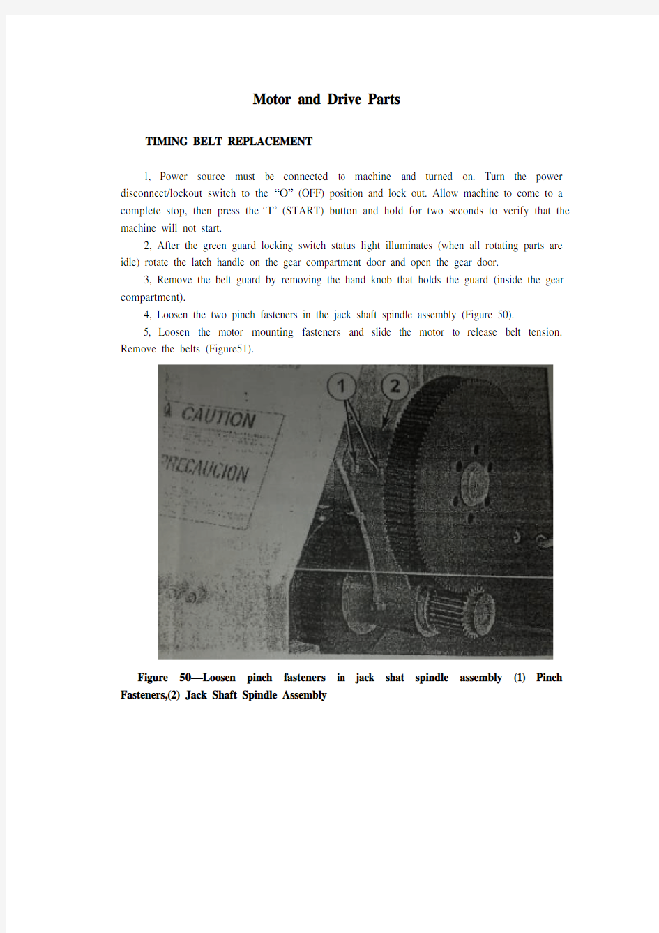
4, Loosen the two pinch fasteners in the jack shaft spindle assembly (Figure 50).
5, Loosen the motor mounting fasteners and slide the motor to release belt tension. Remove the belts (Figure51).
Figure 50—Loosen pinch fasteners in jack shat spindle assembly (1) Pinch Fasteners,(2) Jack Shaft Spindle Assembly
Figure 51 – Timing Belts(1)
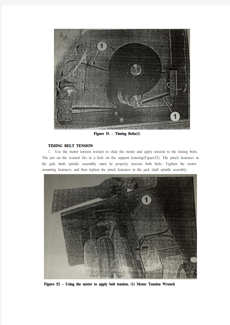
TIMING BELT TENSION
1, Use the motor tension wrench to slide the motor and apply tension to the timing belts. The pin on the wrench fits in a hole on the support housing(Figure52). The pinch fasteners in the jack shaft spindle assembly must be properly tension both belts. Tighten the motor mounting fasteners, and then tighten the pinch fasteners in the jack shaft spindle assembly.
Figure 52 – Using the motor to apply belt tension. (1) Motor Tension Wrench
2, Replace belt guard and tighten with the hand knob.
3, Close and rotate latch handle connecting the gear compartment door and support housing.
Electrical Assembly
INSPECTION
W ARNING: In the event of an electrical problem, only a qualified electrician should inspect or repair the fault. Voltages dangerous to life exist in the starter enclosure! The power disconnect/lockout switch must be in the “O”(OFF) position. Live voltages are still present in the box even though disconnect is off. Always disconnect and lock out power source before beginning electrical inspection or repair.
The electrical assembly must be in good working condition before operating this machine. For a description of the amplifier and safety switch operation and method for checking this system. Electrical schematics are located in the starter enclosure. Refer to Figures53 and 54 and inspect the following:
Figure 53 –Starter enclosure interior with variable frequency drive. (1) Disconnect Switch, (2) Guard Locking Switch Power Disconnect, (3) Main Fuses, (4) Earthing Terminals, (5) Transformer, (6) Transformer Fuses Block, (7) Variable Frequency Drive, (8) Contactor, (9) Standstill Monitor, (10) Control Relay
Figure 54 – Starter enclosure interior, across-the-line start. (1) Disconnect Switch, (2) Guard Locking Switch Power Disconnect, (3) Main Fuses, (4) Earthing Terminals, (5) Transformer, (6) Transformer Fuse Block, (7) Overload Relay, (8) Contactor, (9) Standstill Monitor, (10) Control Relay
Starter enclosure: Inspect interior of starter enclosure for corrosion. If a significant amount of water accumulates in the bottom of the starter enclosure, check the breather drain. Breather drain should be free from obstruction. Excess water could also indicate an opening or loose fitting that allows water to enter the enclosure. Check all access points to the enclosure. Check gasket around door and window. Inspect push/pull stop button, “I”(START) push button assemblies, selector switches and pilot light assembly for damage or corrosion. Replace rubber boots and pilot light lens if damaged.
NOTE: Electrical components that fail due to water or chemical contamination are not covered under the warranty.
Fuses: Remove transformer fuses, located in the transformer fuse blocks. Check with an ohmmeter or continuity light. If one fuse is replaced, all others of that type fuse should also be replaced.
Machines equipped with variable frequency drive(VFD):The drive currently in use is the GPD315/V 7. If the digital display on the drive is not illuminated when the machine is energized, contact Urschel Laboratories.
Standstill monitor: Terminals should be tight and free from corrosion. Monitor must be replaced if damaged.
Power line filter (CE compliant machine with VFD): See the electrical assemblies illustrations in the “Parts” section of this manual for part locations.
Guard locking switches:Replace or straighten actuator key if it is damaged or bent. Check cords for cuts or abrasions. If the green guard locking switch status light does not illuminate when power to the machine is connected, contact Urschel Laboratories. Switch must be replaced if it has been forced open while locked. Use only new screws that are supplied with the switch. Manual release must be in “lock” position when removing and replacing lid( Figure 55).
Figure 55 – Guard Locking Switch. (1) Green Guard Locking Switch Status Light, (2) Guard Locking Switch Manual Release
Green status light must be inside the lens when replacing the lid. To maintain watertight features, securely tighten the seven screws for the lid until there is no gap between lid and switch assembly. Do not over tighten.
NOTE:The two screws located under the lid on the guard locking switch act as special dowel pins locking the switch assembly into place and must not be substituted.
Interrupt switch: Terminals should be tight and free from corrosion. Recommended torque is 5.0 inch pounds (80 inch ounces) or 0.56 Newton-meters. Check sensor, actuator and cord for damage. Switch should be replaced if any defect or damage is defected. Check switch alignment. Actuator must be aligned and within 1/32 (8mm) of sensor to complete safety switch circuit (Figure 56).
WARNING: Always perform the guard locking/interrupt switch system test before operating the machine.
Figure 56 –Interrupt switch sensor and actuator must be aligned and within 1/32”(8mm). (1) Sensor, (2) Actuator
V ARIABLE FREQUENCY DRIVE PROGRAMMING
A replacement variable frequency drive must have frequencies programmed after the drive has been installed into the electrical enclosure. Refer to the “Speed Chart” on your machine or on page 30 in this manual and program the replacement unit according to the following procedure.
WARNING: Starter enclosure must be energized in order to program the drive. Voltages dangerous to life exist when equipment is open and energized! Only a qualified electrician should inspect, install, or program variable frequency drive.
1, Turn power disconnect/lockout switch to “O”(OFF). Open starter enclosure door. Operate the power disconnect/lockout switch mechanism in the enclosure to turn power on.
2, Set the selector switches to the first drive frequency to be programmed. The frequency drive has a digital operator with a display (Figure 57). The display for the GPD 315/V7 drive will read the lowest setting allowed.
Figure 57 – FPD 315 Drive, digital operator. (1) Digital Display,(2) Numeral Change Key, (increase), (3) Numeral Change Key, (decrease), (4) Read/Write Key
3, Enter the speed in the display in hertz. Increase or decrease the value with the “numeral change” keys. See the chart for frequency settings.
CAUTION: Do not attempt to over speed the motor! Over speeding could create a safety hazard and cause excessive wear on machine parts. Under speeding will cause the motor to overheat.
4, With the value correctly displayed and flashing, press the “DATA/ENTER” or “ENTER” key. The display will stop flashing, indicating that the value has been entered.
NOTE:Altering preprogrammed speeds will permanently change these values. To return to original settings, follow steps 1-4.
5, Operate the power disconnect/lockout switch mechanism in the enclosure to turn power off. Close and lock starter enclosure door.
Knife Care
KNIFE CARE GUIDELINES
Knives should be inspected and sharpened or replaced at regular intervals depending upon operating conditions, type of product and hours of operation. Follow these guidelines for best
results:
1, Do not attempt to remove all defects from the knife edge by sharpening.This practice results in shortened knife life. Small defects will not affect knife performance.
2, New knives should not be installed beside worn knives. This arrangement may result in poor quality cuts. Keep all the knives from one spindle in a set and sharpen them together. Periodically check knife width or diameter to make sure all the knives in a set are the same size.
3, Recommended minimum dimensions: The following minimum dimensions are intended to give satisfactory results for most applications. However, each customer must look at the quality of cut on his product to determine at what point knives are resharpened beyond usefulness. The minimum dimensions stated are intended to give satisfactory results for most applications. Some customers may be able to give satisfactory results from knives ground smaller, but some may notice a deterioration in quality of out before the minimum size is reached. Measure crosscut knives from the cutting edge to the back of the knife unless otherwise noted; measure the diameter of circular knives unless otherwise noted.
SHARPENING EQUIPMENT
Urschel Laboratories manufactures machines to quickly and efficiently sharpen knives. The following machine are available;
Model WG honing machine is used to sharpen slicing knives and crosscut knives (straight cut only). For the Model DC, use workrest 33224 for 42281 and 42446 crosscut knives and slicing knife insert .Use workrest 33225 for 42460 crosscut knives. Use workrest 33256 for all other slicing knives.
Model CKG honing machine is used to place the best possible edge on circular knives. The Model CKG can be purchased from the factory ready to sharpen 3-1/2”circular knives for the Model DC. Honers that are not set up to sharpen 3-1/2” circular knives must have certain parts installed. Use the following procedure:
W ARNNING: Honers place an extremely sharp edge on knives; handle knives with care!
1, Make sure the honer is unplugged from the power source.
2, Install hone assembly, knife holder hub and edge roller stud for 3-1/2’’circular knives (Figure 58). The hone assembly (part number 33083) contains the hone bracket and internal parts, the shield and the honing wheel. The stud on the hone bracket is installed in the second hole from the motor shaft (4” knife position). The knife holder hub (part number 33081) is installed with the raised diameter facing out. The edge roller stud (part number 33023) is installed with the set screw in the second spot drilled hole from the outside end (Note that this part number has remained the
same but the part has been modified. The stud should have four spot drilled holes.) 3, Position the hone shield in as far as possible by loosening the screw and sliding the shield. Retighten the screw.
4. Pull the knife clamp hub out of the clamping position. Hold a knife against the knife holder hub. Loosen the set screw in the motor shaft hub and slide the hub and knife on the motor shaft until the knife just touches the honing wheel. Tighten the set screw.
5, Adjust the knife clamp if necessary. The knife clamp should hold the knife against the hub tight enough so that it cannot be rotated yet not so tight that it drives the motor back and distorts the base (the brake arm assembly must be properly adjusted to test for knife rotation). To adjust the knife clamp, loosen the two locking nuts and move the clamp in or out.
6, Place a knife in the honer and sharpen in the normal manner (see the Model CKG instruction manual for more information). If too much of the knife edge is removed, readjust the hub. If insufficient metal is removed, loosen the screw on the hone shield and slide the hone slightly forward against the knife edge.
BUFFING
WARNING: Only qualified trained personnel should buff knives. Use adequate eye and respiratory protection, and a properly guarded buffing wheel. Hold knife securely. Never attempt to catch a dropped knife! Should you drop a knife during the buffing operation, move away and let it tall.
When crosscut knives are sharpened by grinding, filing or honing, a slight wire edge may be produced. Buffing will remove this wire edge.
Install two to four 10" (254 mm) diameter buffing wheels side by side between flanges at least2" (51 mm) in diameter. Buffing wheels and bars of buffing compound are available from Urschel Laboratories (see “Tools", page67).
Turn on the buffer (3600RPM) and hold the bar of buffing compound firmly against the outside diameter of the buffing wheels to apply alight coating of compound. Apply compound frequently to obtain sharp edges quickly.
NOTE: If excess compound is applied, the wheel will harden, making it ineffective.
Should this occur, Use a buffing wheel rake, available from an industrial supplier, to soften the wheel.
When holding knives, be cautions and use a firm grip. Hold the knife firmly with the bevel side up, parallel with and just below the center line of the shaft of the buffer (Figure 58). Push the knife edge into the buffing wheel, penetrating the wheel 1/16"-1/8"(1.5-3mm). Move the knife endwise and buff the entire edge across the buffing wheel with a steady rapid movement in each direction. Several rapid passes are better than one or two slow ones. Do not hold the knife in one area of the buffing wheel too long as the edge may heat and burn. If a burr or wire edge remains, turn the knife over and buff with the bevel side down. Continue buffing, switching from side to side, until wire edge or burr is gone.
Sharpen all sides of crinkle knife edges by tipping the knife endwise at a slight angle, first in one direction and then in the other. Next, the knife is held straight and level to buff the remainder of the cutting edge.
With bevel side up, sharpen side surface of crinkle knife edge by tipping the knife endwise at a slight angle, first in one direction and then in the other. Next, the knife is held straight and level to
buff the remainder of the cutting edge.
Figure 58 –Model CKG honing machine set to sharpen 3-1/2”circular knives (1) Hone Bracket, (2) Mounting Position for Hone Assembly, (3) Knife Holder Hub, (4) Set Screw,(5) Edge Roller Stud (set screw seats in second hole), (6) Hone Shield, (7) Screw, (8) Knife Clamp Hub, (9) Locking Nuts, (10) Honing Wheel
Failure to obtain sharp edges by buffing may be caused by the following:
1, Edges may be too dull or blunt. Blunt edges must always be ground or filed to restore a bevel width and angle similar to that found on a new knife.
2, Knives must be correctly held against the buffing wheel (Figure 59).
3, Too little or too much buffing compound on the wheel.
4, Undersize buffing wheels. Discard the buffing wheels when they are worn to8-3/4" (222 mm) diameter.
Figure 59 – Correct position (top) and incorrect position (bottom) for knife during buffing .(1) Knife, (2) Buffing Wheel
PROBLEM CAUSE CORRECTION
Machine Does Not Start Power disconnect lockout switch is
in the "O"(OFF)position
Turn power disconnect lockout
switch to the "I"(ON) position. Manual release on either of the
guard locking switches is in the
"unlock" position
Turn manual release to the
"lock" position on both
switches, page 17.
Guard locking switch power
disconnect is in the
"O"(OFF)position
Turn guard locking switch
power disconnect to the
"I"(ON) position, page 54.
Push/pull stop button is not pulled
out after being pushed
Pull push/pull stop button out,
page 28.
Covers and guards not securely
closed
Make certain covers and
guards are securely closed.
Check for bent or twisted
brackets that will prevent
switches from lining up. See
"Covers and Guards",
pages34-35.
VFD fault or warning Not error code displayed on
VFD. Turn disconnect off.
电机和传动部件
同步带置换
1,电源必须与机器连接并打开。将电源的断开/锁定档切换到“ 0 ” (关闭)的位置,并锁定。使机器完全停止,然后按下“I” (开始)按钮,并保持两秒钟,以验证该机器将无法启动。
2,在绿色防护装置锁定开关状态指示灯发亮后(当所有旋转部件闲置),旋转齿轮室门的键柄,打开齿轮室门。
3,通过移动支撑防护装置的手柄来拆除带防护装置(内齿轮室)。
4,松开转轴组件的两个夹紧固件(图50 )。
5,松开电机装备固件,滑动电机,释放皮带张力。拆除带(图51)。
图50 —转轴上的夹紧固件,(1)夹紧固件,(2)转轴
图51 —同步带(1)
同步带张力
1,用机动紧张扳手下滑电动机和有紧张力的同步带。扳手的锁销与支撑外壳上的小孔配合适当(图52 )。转轴组件上的夹紧固件必须留适当的紧张力,带也一样。拧紧电机垫板紧固件,然后夹紧转轴上的夹紧固件。
2,更换带防护装置并扳手拧紧。
3,关闭并旋转连接内齿轮室和支撑外壳的键柄。
图52 —用机动紧张扳手来调节带的张紧力(1)电动张紧扳手
电气装配
检验
警告:如果只是在电力方面的问题,一个合格的电工应去检查或修复故障。启动装置表面上带有对人体有危害的电压!电源断开/锁定开关必须打在“0”(关闭)的位置。尽管开关是断开的,但是机壳上仍然有残留电压。必须断开并锁定电源,然后再开始电器检查或修理。
操作这台机器前必须保证电气装配是在良好的工作条件下。为了对操作放大器和安全开关、检查这系统方法的描述,将电气原理图贴在启动装置箱表面上。参阅图53和54,并检查以下内容。
起动装置外壳箱:检查起动装置外壳箱的内部,看看有没有已腐蚀的地方。如果有大量的水积聚在起动装置底部,检查通气的水流失,通气孔应畅通无阻。过多的水可能暗示设备有漏洞或宽松的情况,以至于让污水流入箱体。检查所有与箱体链接的地方。检查门窗周围的垫片。检查推/拉停止按钮,“I” (开始)按钮组件,选择开关和装配上的指示灯是否损坏或腐蚀。如果损坏了的话就用胶靴和标灯透镜来替换。
图53 —带变频器的启动装置箱内部(1)分离开关,(2)护罩紧固分离开关,(3)主要保险丝,(4)接地端,(5)变压器,(6)变压器保险盒,(7)变频器,(8)接触器,(9)停顿显示器,(10)控制继电器
图54 —启动装置箱内部,交叉线的起始点(1)分离开关,(2)护罩紧固分离开关,(3)主要保险丝,(4)接地端,(5)变压器,(6)变压器保险盒,
注意:被水或化学污染损坏的电器元件,不在保修范围以内。
保险丝:拆除变压器保险丝座上的变压器保险丝。观察欧姆表或串联的灯。如果一个保险丝更换,其他所有该类型的保险丝也应更换。
机器配备了变频驱动器(VFD显示):目前,驱动器一般使用的是315 /V7 。设备通电后,如果驱动器上的数字显示仍未发亮,就联系Urschel实验室。
停顿监测:终端设备应保持紧凑和不受腐蚀。如果检测器被损坏了,就必须更换。
电源线滤波器(VFD显示):见手册上部分章节里的电器组件插图。
防护罩锁定开关:如果促动器键损坏或弯曲,更换或拉直。检查电线是否有破口或磨损的情况。设备接通电源后,如果绿色防护开关状态指示灯不照亮,联系Urschel实验室。如果强行打开了开关,而一段时间后又自动关闭,那必须更换开关。只要使用开关提供的新螺丝钉。当拆除和更换箱盖时,手动解锁装置必须在“锁定”的位置(图55)。
图55 —防护罩固定开关(1)绿色防护罩固定开关状态指示灯,(2)防护罩手动解锁
更换盖子时,绿色状态指示灯必须在更换镜头里面。为了保持水密功能,尽量用力拧紧盖子的七个螺丝钉,直到盖子和开关组件之间没有间距为止,但千万不能拧得太紧。
注意:两个螺丝位于盖子下面的保护闸开关上,以起到用专门合销来控制锁定开关组件在一定位置的作用,这种合销绝不能用其他组件来来取代。
中断开关:终端设备应保持紧凑和不受腐蚀。建议扭矩为5.0英寸磅(80英寸盎司)或0.56牛顿/米。检查传感器、驱动器和电线的损坏情况。如开关有任何缺陷,应及时更换。检查开关是否对齐。推进器必须在传感器里面的1/32(8毫米)处,以完成安全开关电路(图56)。
警告:操作该机器前一定要进行保户闸/中断开关系统的测试。
图56 —传感器和推进器必须成一线,并推进器必须在传感器里面的1/32(8毫米)处(1)传感器,(2)推进器
变频驱动器的设计
驱动器已安装到电器外壳后,要更换变频驱动器就必须得有频率设计。在设备上或手册中的30页都涉及到“速率图”,根据下面的程序设计它的替换单位。
警告:为了设计驱动器,必须给起动机外壳提供电压。当设备运行和供电时,它上面带有对生命危险的电压!只有合格的电气技师才能检查,安装,或设计变频驱动器。
1,将电源断开/锁定开关切换到“ O”(关闭),打开起动机外壳门,将电源断开/
锁定开关接到外壳里面的机器上,打开电源。
2,设置一个编好了驱动频率程序的选择开关,频率驱动器有一个操作标记的数字显示(图57)。将可以从这台GPD315/V7驱动器上的显示器上读出允许设置的最低值。
图57 —FPD 315 驱动器,数字式操作标记(1)数字显示,(2)数字变动键(增加),(3)数字变动键(减小),(4) 读/写键
3,输入的速率时显示的是赫兹。用数字键增加或减少数值,从图表中观察频率设置。
警告:不要尝试让电动机超速!超速可能造成安全隐患,使机器部件过磨损,超速运行还将导致发动机过热。
4,当数值正确的显示并闪烁时,按下“ DATA/ENTER”键或“ Enter”键,该显示器将停止闪烁,这表明该数值已输入。
注意:改变预先设定好的速度将永久地改变这些值,要返回到原来的设置,请按照遵循步骤1-4。
5,将电源断开/锁定开关打在开断位置,关闭起动机外箱的门,并锁紧。
刀具维护
中英文文献翻译
毕业设计(论文)外文参考文献及译文 英文题目Component-based Safety Computer of Railway Signal Interlocking System 中文题目模块化安全铁路信号计算机联锁系统 学院自动化与电气工程学院 专业自动控制 姓名葛彦宁 学号 200808746 指导教师贺清 2012年5月30日
Component-based Safety Computer of Railway Signal Interlocking System 1 Introduction Signal Interlocking System is the critical equipment which can guarantee traffic safety and enhance operational efficiency in railway transportation. For a long time, the core control computer adopts in interlocking system is the special customized high-grade safety computer, for example, the SIMIS of Siemens, the EI32 of Nippon Signal, and so on. Along with the rapid development of electronic technology, the customized safety computer is facing severe challenges, for instance, the high development costs, poor usability, weak expansibility and slow technology update. To overcome the flaws of the high-grade special customized computer, the U.S. Department of Defense has put forward the concept:we should adopt commercial standards to replace military norms and standards for meeting consumers’demand [1]. In the meantime, there are several explorations and practices about adopting open system architecture in avionics. The United Stated and Europe have do much research about utilizing cost-effective fault-tolerant computer to replace the dedicated computer in aerospace and other safety-critical fields. In recent years, it is gradually becoming a new trend that the utilization of standardized components in aerospace, industry, transportation and other safety-critical fields. 2 Railways signal interlocking system 2.1 Functions of signal interlocking system The basic function of signal interlocking system is to protect train safety by controlling signal equipments, such as switch points, signals and track units in a station, and it handles routes via a certain interlocking regulation. Since the birth of the railway transportation, signal interlocking system has gone through manual signal, mechanical signal, relay-based interlocking, and the modern computer-based Interlocking System. 2.2 Architecture of signal interlocking system Generally, the Interlocking System has a hierarchical structure. According to the function of equipments, the system can be divided to the function of equipments; the system
建筑类外文文献及中文翻译
forced concrete structure reinforced with an overviewRein Since the reform and opening up, with the national economy's rapid and sustained development of a reinforced concrete structure built, reinforced with the development of technology has been great. Therefore, to promote the use of advanced technology reinforced connecting to improve project quality and speed up the pace of construction, improve labor productivity, reduce costs, and is of great significance. Reinforced steel bars connecting technologies can be divided into two broad categories linking welding machinery and steel. There are six types of welding steel welding methods, and some apply to the prefabricated plant, and some apply to the construction site, some of both apply. There are three types of machinery commonly used reinforcement linking method primarily applicable to the construction site. Ways has its own characteristics and different application, and in the continuous development and improvement. In actual production, should be based on specific conditions of work, working environment and technical requirements, the choice of suitable methods to achieve the best overall efficiency. 1、steel mechanical link 1.1 radial squeeze link Will be a steel sleeve in two sets to the highly-reinforced Department with superhigh pressure hydraulic equipment (squeeze tongs) along steel sleeve radial squeeze steel casing, in squeezing out tongs squeeze pressure role of a steel sleeve plasticity deformation closely integrated with reinforced through reinforced steel sleeve and Wang Liang's Position will be two solid steel bars linked Characteristic: Connect intensity to be high, performance reliable, can bear high stress draw and pigeonhole the load and tired load repeatedly.
【机械类文献翻译】步进电机和伺服电机的系统控制
Step Motor Motor&&Servo Motor Systems and Controls Motion Architect?Software Does the Work for You...Configure,Diagnose,Debug Compumotor’s Motion Architect is a Microsoft?Windows?-based software development tool for6000Series products that allows you to automatically generate commented setup code,edit and execute motion control programs,and create a custom operator test panel.The heart of Motion Architect is the shell,which provides an integrated environment to access the following modules. ?System Configurator—This module prompts you to fill in all pertinent set-up information to initiate motion.Configurable to the specific6000Series product that is selected,the information is then used to generate actual6000-language code that is the beginning of your program. ?Program Editor—This module allows you to edit code.It also has the commands available through“Help”menus.A user’s guide is provided on disk. ?Terminal Emulator—This module allows you to interact directly with the6000product.“Help”is again available with all commands and their definitions available for reference.?Test Panel—You can simulate your programs,debug programs,and check for program flow using this module. Motion Architect?has been designed for use with all6000Series products—for both servo and stepper technologies.The versatility of Windows and the6000Series language allow you to solve applications ranging from the very simple to the complex. Motion Architect comes standard with each of the6000Series products and is a tool that makes using these controllers even more simple—shortening the project development time considerably.A value-added feature of Motion Architect,when used with the6000 Servo Controllers,is its tuning aide.This additional module allows you to graphically display a variety of move parameters and see how these parameters change based on tuning values. Using Motion Architect,you can open multiple windows at once.For example,both the Program Editor and Terminal Emulator windows can be opened to run the program,get information,and then make changes to the program. On-line help is available throughout Motion Architect,including interactive access to the contents of the Compumotor6000Series Software Reference Guide. SOLVING APPLICATIONS FROM SIMPLE TO COMPLEX Servo Control is Yours with Servo Tuner Software Compumotor combines the6000Series servo controllers with Servo Tuner software.The Servo Tuner is an add-on module that expands and enhances the capabilities of Motion Architect?. Motion Architect and the Servo Tuner combine to provide graphical feedback of
文献翻译英文原文
https://www.360docs.net/doc/834594466.html,/finance/company/consumer.html Consumer finance company The consumer finance division of the SG group of France has become highly active within India. They plan to offer finance for vehicles and two-wheelers to consumers, aiming to provide close to Rs. 400 billion in India in the next few years of its operations. The SG group is also dealing in stock broking, asset management, investment banking, private banking, information technology and business processing. SG group has ventured into the rapidly growing consumer credit market in India, and have plans to construct a headquarters at Kolkata. The AIG Group has been approved by the RBI to set up a non-banking finance company (NBFC). AIG seeks to introduce its consumer finance and asset management businesses in India. AIG Capital India plans to emphasize credit cards, mortgage financing, consumer durable financing and personal loans. Leading Indian and international concerns like the HSBC, Deutsche Bank, Goldman Sachs, Barclays and HDFC Bank are also waiting to be approved by the Reserve Bank of India to initiate similar operations. AIG is presently involved in insurance and financial services in more than one hundred countries. The affiliates of the AIG Group also provide retirement and asset management services all over the world. Many international companies have been looking at NBFC business because of the growing consumer finance market. Unlike foreign banks, there are no strictures on branch openings for the NBFCs. GE Consumer Finance is a section of General Electric. It is responsible for looking after the retail finance operations. GE Consumer Finance also governs the GE Capital Asia. Outside the United States, GE Consumer Finance performs its operations under the GE Money brand. GE Consumer Finance currently offers financial services in more than fifty countries. The company deals in credit cards, personal finance, mortgages and automobile solutions. It has a client base of more than 118 million customers throughout the world
伺服电机外文文献翻译
伺服电机 1. 伺服电机的定义 伺服电动机又称执行电动机,在自动控制系统中,用作执行元件,把所收到的电信号转换成电动机轴上的角位移或角速度输出。分为直流和交流伺服电动机两大类,其主要特点是,当信号电压为零时无自转现象,转速随着转矩的增加而匀速下降。伺服电机在伺服系统中控制机械元件运转的发动机. 是一种补助马达间接变速装置。伺服电机可使控制速度, 位置精度非常准确。将电压信号转化为转矩和转速以驱动控制对象。转子转速受输入信号控制,并能快速反应,在自动控制系统中作执行元件,且具有机电时间常数小、线性度高、始动电压低等特点。 2. 伺服电机工作原理 1.伺服主要靠脉冲来定位,基本上可以这样理解,伺服电机接收到1 个脉冲,就会旋转1 个脉冲对应的角度,从而实现位移,因为,伺服电机本身具备发出脉冲的功能,所以伺服电机每旋转一个角度,都会发出对应数量的脉冲,这样,和伺服电机接受的脉冲形成了呼应,或者叫闭环,如此一来,系统就会知道发了多少脉冲给伺服电机,同时又收了多少脉冲回来,这样,就能够很精确的控制电机的转动,从而实现精确的定位,可以达到0.001mm有刷电机成本低,结构简单,启动转矩大,调速范围宽,控制容易,需要维护,但维护方便(换碳刷),产生电磁干扰,对环境有要求。无刷电机体积小,重量轻,出力大,响应快,速度高,惯量小,转动平滑,力矩稳定。控制复杂,容易实现智能化,其电子换相方式灵活,可以方波换相或正弦波换相。电机免维护,效率很高,运行温度低,电磁辐射很小,长寿命,可用于各种环境。 2. 交流伺服电机也是无刷电机,分为同步和异步电机,目前运动控制中一般都用同步电机,它的功率范围大,可以做到很大的功率。大惯量,最高转动速度低,且随着功率增大而快速降低。因而适合做低速平稳运行的应用。 3. 永磁交流伺服电动机简介 20 世纪80 年代以来,随着集成电路、电力电子技术和交流可变速驱动技术的发展,永磁交流伺服驱动技术有了突出的发展,各国著名电气厂商相继推出各自的交流伺服电动机和伺服驱动器系列产品并不断完善和更新。交流伺服系统已成为当代高性能伺服系统的主要发展方向,使原来的直流伺服面临被淘汰的危机。90 年代以后,世界各国已经商品化了的交流伺服系统是采用全数字控制的正弦
英文文献翻译
中等分辨率制备分离的 快速色谱技术 W. Clark Still,* Michael K a h n , and Abhijit Mitra Departm(7nt o/ Chemistry, Columbia Uniuersity,1Veu York, Neu; York 10027 ReceiLied January 26, 1978 我们希望找到一种简单的吸附色谱技术用于有机化合物的常规净化。这种技术是适于传统的有机物大规模制备分离,该技术需使用长柱色谱法。尽管这种技术得到的效果非常好,但是其需要消耗大量的时间,并且由于频带拖尾经常出现低复原率。当分离的样本剂量大于1或者2g时,这些问题显得更加突出。近年来,几种制备系统已经进行了改进,能将分离时间减少到1-3h,并允许各成分的分辨率ΔR f≥(使用薄层色谱分析进行分析)。在这些方法中,在我们的实验室中,媒介压力色谱法1和短柱色谱法2是最成功的。最近,我们发现一种可以将分离速度大幅度提升的技术,可用于反应产物的常规提纯,我们将这种技术称为急骤色谱法。虽然这种技术的分辨率只是中等(ΔR f≥),而且构建这个系统花费非常低,并且能在10-15min内分离重量在的样本。4 急骤色谱法是以空气压力驱动的混合介质压力以及短柱色谱法为基础,专门针对快速分离,介质压力以及短柱色谱已经进行了优化。优化实验是在一组标准条件5下进行的,优化实验使用苯甲醇作为样本,放在一个20mm*5in.的硅胶柱60内,使用Tracor 970紫外检测器监测圆柱的输出。分辨率通过持续时间(r)和峰宽(w,w/2)的比率进行测定的(Figure 1),结果如图2-4所示,图2-4分别放映分辨率随着硅胶颗粒大小、洗脱液流速和样本大小的变化。
土木工程外文文献翻译
专业资料 学院: 专业:土木工程 姓名: 学号: 外文出处:Structural Systems to resist (用外文写) Lateral loads 附件:1.外文资料翻译译文;2.外文原文。
附件1:外文资料翻译译文 抗侧向荷载的结构体系 常用的结构体系 若已测出荷载量达数千万磅重,那么在高层建筑设计中就没有多少可以进行极其复杂的构思余地了。确实,较好的高层建筑普遍具有构思简单、表现明晰的特点。 这并不是说没有进行宏观构思的余地。实际上,正是因为有了这种宏观的构思,新奇的高层建筑体系才得以发展,可能更重要的是:几年以前才出现的一些新概念在今天的技术中已经变得平常了。 如果忽略一些与建筑材料密切相关的概念不谈,高层建筑里最为常用的结构体系便可分为如下几类: 1.抗弯矩框架。 2.支撑框架,包括偏心支撑框架。 3.剪力墙,包括钢板剪力墙。 4.筒中框架。 5.筒中筒结构。 6.核心交互结构。 7. 框格体系或束筒体系。 特别是由于最近趋向于更复杂的建筑形式,同时也需要增加刚度以抵抗几力和地震力,大多数高层建筑都具有由框架、支撑构架、剪力墙和相关体系相结合而构成的体系。而且,就较高的建筑物而言,大多数都是由交互式构件组成三维陈列。 将这些构件结合起来的方法正是高层建筑设计方法的本质。其结合方式需要在考虑环境、功能和费用后再发展,以便提供促使建筑发展达到新高度的有效结构。这并
不是说富于想象力的结构设计就能够创造出伟大建筑。正相反,有许多例优美的建筑仅得到结构工程师适当的支持就被创造出来了,然而,如果没有天赋甚厚的建筑师的创造力的指导,那么,得以发展的就只能是好的结构,并非是伟大的建筑。无论如何,要想创造出高层建筑真正非凡的设计,两者都需要最好的。 虽然在文献中通常可以见到有关这七种体系的全面性讨论,但是在这里还值得进一步讨论。设计方法的本质贯穿于整个讨论。设计方法的本质贯穿于整个讨论中。 抗弯矩框架 抗弯矩框架也许是低,中高度的建筑中常用的体系,它具有线性水平构件和垂直构件在接头处基本刚接之特点。这种框架用作独立的体系,或者和其他体系结合起来使用,以便提供所需要水平荷载抵抗力。对于较高的高层建筑,可能会发现该本系不宜作为独立体系,这是因为在侧向力的作用下难以调动足够的刚度。 我们可以利用STRESS,STRUDL 或者其他大量合适的计算机程序进行结构分析。所谓的门架法分析或悬臂法分析在当今的技术中无一席之地,由于柱梁节点固有柔性,并且由于初步设计应该力求突出体系的弱点,所以在初析中使用框架的中心距尺寸设计是司空惯的。当然,在设计的后期阶段,实际地评价结点的变形很有必要。 支撑框架 支撑框架实际上刚度比抗弯矩框架强,在高层建筑中也得到更广泛的应用。这种体系以其结点处铰接或则接的线性水平构件、垂直构件和斜撑构件而具特色,它通常与其他体系共同用于较高的建筑,并且作为一种独立的体系用在低、中高度的建筑中。
数控加工外文翻译
数控加工中心技术发展趋势及对策 原文来源:Zhao Chang-ming Liu Wang-ju (CNC Machining Process and equipment, 2002,China) 一、摘要 Equip the engineering level, level of determining the whole national economy of the modernized degree and modernized degree of industry, numerical control technology is it develop new developing new high-tech industry and most advanced industry to equip (such as information technology and his industry, biotechnology and his industry, aviation, spaceflight, etc. national defense industry) last technology and getting more basic most equipment. Numerical control technology is the technology controlled to mechanical movement and working course with digital information, integrated products of electromechanics that the numerical control equipment is the new technology represented by numerical control technology forms to the manufacture industry of the tradition and infiltration of the new developing manufacturing industry, Keywords:Numerical ControlTechnology, E quipment,industry 二、译文 数控技术和装备发展趋势及对策 装备工业的技术水平和现代化程度决定着整个国民经济的水平和现代化程度,数控技术及装备是发展新兴高新技术产业和尖端工业(如信息技术及其产业、生物技术及其产业、航空、航天等国防工业产业)的使能技术和最基本的装备。马克思曾经说过“各种经济时代的区别,不在于生产什么,而在于怎样生产,用什么劳动资料生产”。制造技术和装备就是人类生产活动的最基本的生产资料,而数控技术又是当今先进制造技术和装备最为核心的技术。当今世界各国制造业广泛采用数控技术,以提高制造能力和水平,提高对动态多变市场的适应能力和竞争能力。此外,世界上各工业发达国家还将数控技术及数控装备列为国家的战
直流电动机中英文对照外文翻译文献
中英文对照外文翻译文献 (文档含英文原文和中文翻译) 外文文献: DC Motor Calculations Overview Now that we have a good understanding of dc generators, we can begin our study of dc motors. Direct-current motors transform electrical energy into mechanical energy. They drive devices such as hoists, fans, pumps, calendars, punch-presses, and cars. These devices may have a definite torque-speed characteristic (such as a pump or fan) or a highly variable one (such as a hoist or automobile). The torque-speed characteristic of the motor must be adapted to the type of the load it has to drive, and this requirement has given rise to three basic types of motors: 1.
Shunt motors 2. Series motors 3. Compound motors Direct-current motors are seldom used in ordinary industrial applications because all electric utility systems furnish alternating current. However, for special applications such as in steel mills, mines, and electric trains, it is sometimes advantageous to transform the alternating current into direct current in order to use dc motors. The reason is that the torque-speed characteristics of dc motors can be varied over a wide range while retaining high efficiency. Today, this general statement can be challenged because the availability of sophisticated electronic drives has made it possible to use alternating current motors for variable speed applications. Nevertheless, there are millions of dc motors still in service and thousands more are being produced every year. Counter-electromotive force (cemf) Direct-current motors are built the same way as generators are; consequently, a dc machine can operate either as a motor or as a generator. To illustrate, consider a dc generator in which the armature, initially at rest, is connected to a dc source E s by means of a switch (Fig. 5.1). The armature has a resistance R, and the magnetic field is created by a set of permanent magnets. As soon as the switch is closed, a large current flows in the armature because its resistance is very low. The individual armature conductors are immediately subjected to a force because they are immersed in the magnetic field created by the permanent magnets. These forces add up to produce a powerful torque, causing the armature to rotate. Figure 5.1 Starting a dc motor across the line.
英文文献及中文翻译
毕业设计说明书 英文文献及中文翻译 学院:专 2011年6月 电子与计算机科学技术软件工程
https://www.360docs.net/doc/834594466.html, Overview https://www.360docs.net/doc/834594466.html, is a unified Web development model that includes the services necessary for you to build enterprise-class Web applications with a minimum of https://www.360docs.net/doc/834594466.html, is part of https://www.360docs.net/doc/834594466.html, Framework,and when coding https://www.360docs.net/doc/834594466.html, applications you have access to classes in https://www.360docs.net/doc/834594466.html, Framework.You can code your applications in any language compatible with the common language runtime(CLR), including Microsoft Visual Basic and C#.These languages enable you to develop https://www.360docs.net/doc/834594466.html, applications that benefit from the common language runtime,type safety, inheritance,and so on. If you want to try https://www.360docs.net/doc/834594466.html,,you can install Visual Web Developer Express using the Microsoft Web Platform Installer,which is a free tool that makes it simple to download,install,and service components of the Microsoft Web Platform.These components include Visual Web Developer Express,Internet Information Services (IIS),SQL Server Express,and https://www.360docs.net/doc/834594466.html, Framework.All of these are tools that you use to create https://www.360docs.net/doc/834594466.html, Web applications.You can also use the Microsoft Web Platform Installer to install open-source https://www.360docs.net/doc/834594466.html, and PHP Web applications. Visual Web Developer Visual Web Developer is a full-featured development environment for creating https://www.360docs.net/doc/834594466.html, Web applications.Visual Web Developer provides an ideal environment in which to build Web sites and then publish them to a hosting https://www.360docs.net/doc/834594466.html,ing the development tools in Visual Web Developer,you can develop https://www.360docs.net/doc/834594466.html, Web pages on your own computer.Visual Web Developer includes a local Web server that provides all the features you need to test and debug https://www.360docs.net/doc/834594466.html, Web pages,without requiring Internet Information Services(IIS)to be installed. Visual Web Developer provides an ideal environment in which to build Web sites and then publish them to a hosting https://www.360docs.net/doc/834594466.html,ing the development tools in Visual Web Developer,you can develop https://www.360docs.net/doc/834594466.html, Web pages on your own computer.
土木工程专业外文文献及翻译
( 二 〇 一 二 年 六 月 外文文献及翻译 题 目: About Buiding on the Structure Design 学生姓名: 学 院:土木工程学院 系 别:建筑工程系 专 业:土木工程(建筑工程方向) 班 级:土木08-4班 指导教师:
英文原文: Building construction concrete crack of prevention and processing Abstract The crack problem of concrete is a widespread existence but again difficult in solve of engineering actual problem, this text carried on a study analysis to a little bit familiar crack problem in the concrete engineering, and aim at concrete the circumstance put forward some prevention, processing measure. Keyword:Concrete crack prevention processing Foreword Concrete's ising 1 kind is anticipate by the freestone bone, cement, water and other mixture but formation of the in addition material of quality brittleness not and all material.Because the concrete construction transform with oneself, control etc. a series problem, harden model of in the concrete existence numerous tiny hole, spirit cave and tiny crack, is exactly because these beginning start blemish of existence just make the concrete present one some not and all the characteristic of quality.The tiny crack is a kind of harmless crack and accept concrete heavy, defend Shen and a little bit other use function not a creation to endanger.But after the concrete be subjected to lotus carry, difference in temperature etc. function, tiny crack would continuously of expand with connect, end formation we can see without the