汽车悬架工作原理全英文
How Car Suspensions Work
Table of Contents:
? Introduction to How Car Suspensions Work
? Vehicle Dynamics
? The Chassis
? Springs
? Springs: Sprung and Unsprung Mass
? Dampers: Shock Absorbers
? Dampers: Struts and Anti-sway Bars
? Suspension Types: Front
? Suspension Types: Rear
? Specialized Suspensions: The Baja Bug
? Specialized Suspensions: Formula One Racers
? Specialized Suspensions: Hot Rods
? The Future of Car Suspensions
? Lots More Information
? Compare Prices for Car Suspensions
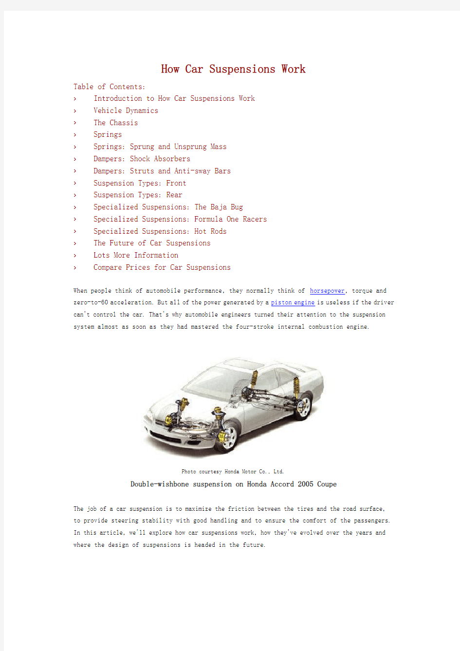
When people think of automobile performance, they normally think of horsepower, torque and zero-to-60 acceleration. But all of the power generated by a piston engine is useless if the driver can't control the car. That's why automobile engineers turned their attention to the suspension system almost as soon as they had mastered the four-stroke internal combustion engine.
Photo courtesy Honda Motor Co., Ltd.
Double-wishbone suspension on Honda Accord 2005 Coupe
The job of a car suspension is to maximize the friction between the tires and the road surface, to provide steering stability with good handling and to ensure the comfort of the passengers. In this article, we'll explore how car suspensions work, how they've evolved over the years and where the design of suspensions is headed in the future.
Vehicle Dynamics(汽车动力学)
If a road were perfectly flat, with no irregularities, suspensions wouldn't be necessary. But roads are far from flat. Even freshly paved highways have subtle imperfections that can interact with the wheels of a car. It's these imperfections that apply forces to the wheels. According to Newton's laws of motion(牛顿运动理论), all forces have both magnitude(大小) and direction.
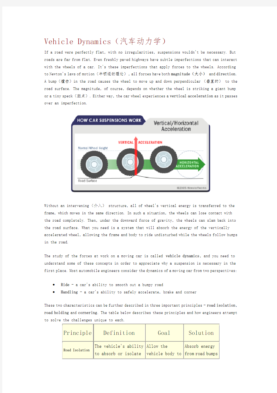
A bump(撞击)in the road causes the wheel to move up and down perpendicular(垂直的) to the road surface. The magnitude, of course, depends on whether the wheel is striking a giant bump or a tiny speck(斑点). Either way, the car wheel experiences a vertical acceleration as it passes over an imperfection.
Without an intervening(介入) structure, all of wheel's vertical energy is transferred to the frame, which moves in the same direction. In such a situation, the wheels can lose contact with the road completely. Then, under the downward force of gravity, the wheels can slam back into the road surface. What you need is a system that will absorb the energy of the vertically accelerated wheel, allowing the frame and body to ride undisturbed while the wheels follow bumps in the road.
The study of the forces at work on a moving car is called vehicle dynamics, and you need to understand some of these concepts in order to appreciate why a suspension is necessary in the first place. Most automobile engineers consider the dynamics of a moving car from two perspectives:
?Ride - a car's ability to smooth out a bumpy road
?Handling - a car's ability to safely accelerate, brake and corner
These two characteristics can be further described in three important principles - road isolation, road holding and cornering. The table below describes these principles and how engineers attempt to solve the challenges unique to each.
Principle Definition Goal Solution
Road Isolation The vehicle's ability
to absorb or isolate
Allow the
vehicle body to
Absorb energy
from road bumps
A car's suspension, with its various components, provides all of the solutions described.
Let's look at the parts of a typical suspension, working from the bigger picture of the chassis down to the individual components that make up the suspension proper.
The Chassis
The suspension of a car is actually part of the chassis, which comprises all of the important systems located beneath the car's body.
Chassis
These systems include:
?The frame- structural, load-carrying component that supports the car's engine and body, which are in turn supported by the suspension
?The suspension system - setup that supports weight, absorbs and dampens shock and helps maintain tire contact
?The steering system - mechanism that enables the driver to guide and direct the vehicle ?The tires and wheels- components that make vehicle motion possible by way of grip and/or friction with the road
So the suspension is just one of the major systems in any vehicle.
With this big-picture overview in mind, it's time to look at the three fundamental components of any suspension: springs, dampers and anti-sway bars.
Springs
Today's springing systems are based on one of four basic designs:
? Coil springs - This is the most common type of spring and is, in essence, a heavy-duty
torsion bar coiled around an axis. Coil springs compress and expand to absorb the motion
of the wheels.
Photo courtesy Car Domain
Coil springs
? Leaf springs - This type of spring consists
of several layers of metal (called "leaves")
bound together to act as a single unit. Leaf
springs were first used on horse-drawn
carriages and were found on most American automobiles until 1985. They are still used today on most trucks and heavy-duty vehicles. ? Torsion bars - Torsion bars (扭力杆) use the twisting properties of a steel bar to provide
coil-spring-like performance. This is how they work: One end of a bar is anchored to the vehicle frame. The other end is attached to a wishbone, which acts like a lever that moves perpendicular to the torsion bar. When the wheel hits a bump, vertical motion is
transferred to the wishbone and then, through the levering action, to the torsion bar. The torsion bar then twists along its axis to provide the spring force. European carmakers used this system extensively, as did Packard and Chrysler in the United States, through the 1950s and 1960s.
Photo courtesy HowStuffWorks Shopper Leaf spring
Photo courtesy HowStuffWorks Shopper
Torsion bar
?Air springs- Air springs, which consist of a cylindrical chamber of air positioned between the wheel and the car's body, use the compressive qualities of air to absorb wheel
vibrations. The concept is actually more than a century old and could be found on
horse-drawn buggies. Air springs from this era were made from air-filled, leather
diaphragms, much like a bellows; they were replaced with molded-rubber(橡胶浇筑) air springs in the 1930s.
Photo courtesy HSW Shopper
Air springs
Based on where springs are located on a car -- i.e., between the wheels and the frame -- engineers often find it convenient to talk about the sprung mass and the unsprung mass.
Springs: Sprung and Unsprung Mass(簧下质量)The sprung mass is the mass of the vehicle supported on the springs, while the unsprung mass is loosely defined as the mass between the road and the suspension springs. The stiffness of the springs affects how the sprung mass responds while the car is being driven. Loosely sprung cars, such as luxury cars (think Lincoln Town Car), can swallow bumps and provide a super-smooth ride; however, such a car is prone to dive and squat during braking and acceleration and tends to experience body sway or roll during cornering. Tightly sprung cars, such as sports cars (think
Mazda Miata), are less forgiving on bumpy roads, but they minimize body motion well, which means they can be driven aggressively, even around corners.
So, while springs by themselves seem like simple devices, designing and implementing them on a car to balance passenger comfort with handling is a complex task. And to make matters more complex, springs alone can't provide a perfectly smooth ride. Why? Because springs are great at absorbing energy, but not so good at dissipating it. Other structures, known as dampers, are required to do this.
Dampers: Shock Absorbers
Unless a dampening structure is present, a car spring will extend and release the energy it absorbs from a bump at an uncontrolled rate. The spring will continue to bounce(反弹) at its natural frequency until all of the energy originally put into it is used up. A suspension built on springs alone would make for an extremely bouncy ride and, depending on the terrain, an uncontrollable car.
Enter the shock absorber, or snubber(缓冲器), a device that controls unwanted spring motion through a process known as dampening. Shock absorbers slow down and reduce the magnitude of vibratory motions by turning the kinetic energy (动能)of suspension movement into heat energy that can be dissipated through hydraulic fluid. To understand how this works, it's best to look inside a shock absorber to see its structure and function.
A shock absorber is basically an oil pump placed between the frame of the car and the wheels. The upper mount of the shock connects to the frame (i.e., the sprung weight), while the lower mount connects to the axle, near the wheel (i.e., the unsprung weight). In a twin-tube design, one of the most common types of shock absorbers, the upper mount is connected to a piston rod, which in turn is connected to a piston, which in turn sits in a tube filled with hydraulic fluid. The inner tube is known as the pressure tube, and the outer tube is known as the reserve tube. The reserve tube stores excess hydraulic fluid.
When the car wheel encounters a bump in the road and causes the spring to coil and uncoil, the energy of the spring is transferred to the shock absorber through the upper mount, down through the piston rod and into the piston. Orifices perforate the piston and allow fluid to leak through as the piston moves up and down in the pressure tube. Because the orifices are relatively tiny, only a small amount of fluid, under great pressure, passes through. This slows down the piston, which in turn slows down the spring.
Shock absorbers work in two cycles -- the compression cycle and the extension cycle. The compression cycle occurs as the piston moves downward, compressing the hydraulic fluid in the chamber below the piston. The extension cycle occurs as the piston moves toward the top of the pressure tube, compressing the fluid in the chamber above the piston. A typical car or light truck will have more resistance during its extension cycle than its compression cycle. With that in
mind, the compression cycle controls the motion of the vehicle's unsprung weight, while extension controls the heavier, sprung weight.
All modern shock absorbers are velocity-sensitive -- the faster the suspension moves, the more resistance the shock absorber provides. This enables shocks to adjust to road conditions and to control all of the unwanted motions that can occur in a moving vehicle, including bounce, sway, brake dive and acceleration squat.
Dampers: Struts and Anti-sway Bars
Another common dampening structure is the strut -- basically a shock absorber mounted inside a coil spring. Struts perform two jobs: They provide a dampening function like shock absorbers, and they provide structural support for the vehicle suspension. That means struts deliver a bit more than shock absorbers, which don't support vehicle weight -- they only control the speed at which weight is transferred in a car, not the weight itself.
Common strut design
Because shocks and struts have so much to do with the handling of a car, they can be considered critical safety features. Worn shocks and struts can allow excessive vehicle-weight transfer from side to side and front to back. This reduces the tire's ability to grip the road, as well as handling and braking performance.
Anti-sway Bars(稳定杆)
Anti-sway bars (also known as anti-roll bars) are used along with shock absorbers or struts to give a moving automobile additional stability. An anti-sway bar is a metal rod that spans the entire axle and effectively joins each side of the suspension together.
Photo courtesy HSW Shopper
Anti-sway bars
When the suspension at one wheel moves up and down, the anti-sway bar transfers movement to the other wheel. This creates a more level ride and reduces vehicle sway. In particular, it combats the roll of a car on its suspension as it corners. For this reason, almost all cars today are fitted with anti-sway bars as standard equipment, although if they're not, kits make it easy to install the bars at any time.
Suspension Types: Front
So far, our discussions have focused on how springs and dampers function on any given wheel. But the four wheels of a car work together in two independent systems -- the two wheels connected by the front axle and the two wheels connected by the rear axle. That means that a car can and usually does have a different type of suspension on the front and back. Much is determined by whether a rigid axle binds the wheels or if the wheels are permitted to move independently. The former arrangement is known as a dependent system, while the latter arrangement is known as an independent system. In the following sections, we'll look at some of the common types of front and back suspensions typically used on mainstream cars.
Front Suspension - Dependent Systems
Dependent front suspensions have a rigid front axle that connects the front wheels. Basically, this looks like a solid bar under the front of the car, kept in place by leaf springs and shock absorbers. Common on trucks, dependent front suspensions haven't been used in mainstream cars for years.
Front Suspension - Independent Systems
In this setup, the front wheels are allowed to move independently. The MacPherson strut, developed by Earle S. MacPherson of General Motors in 1947, is the most widely used front suspension system, especially in cars of European origin.
The MacPherson strut combines a shock absorber and a coil spring into a single unit. This provides a more compact and lighter suspension system that can be used for front-wheel drive vehicles.
The double-wishbone suspension, also known as an A-arm suspension, is another common type of front independent suspension.
Photo courtesy Honda Motor Co., Ltd.
Double-wishbone suspension on Honda Accord 2005 Coupe
While there are several different possible configurations, this design typically uses two wishbone-shaped arms to locate the wheel. Each wishbone, which has two mounting positions to the frame and one at the wheel, bears a shock absorber and a coil spring to absorb vibrations. Double-wishbone suspensions allow for more control over the camber angle of the wheel, which describes the degree to which the wheels tilt in and out. They also help minimize roll or sway and provide for a more consistent steering feel. Because of these characteristics, the double-wishbone suspension is common on the front wheels of larger cars.
Now let's look at some common rear suspensions.
Suspension Types: Rear
Rear Suspension - Dependent Systems
If a solid axle connects the rear wheels of a car, then the
suspension is usually quite simple -- based either on a leaf spring or a coil spring. In the former design, the leaf springs
clamp directly to the drive axle. The ends of the leaf springs
attach directly to the frame, and the shock absorber is attached at the clamp that holds the spring to the axle. For many years, American car manufacturers preferred this design because of its simplicity.
The same basic design can be achieved with coil springs replacing the leaves. In this case, the spring and shock absorber can be mounted as a single unit or as separate components. When they're separate, the springs can be much smaller, which reduces the amount of space the suspension takes up. Rear Suspension - Independent Suspensions
If both the front and back suspensions are independent, then all of the wheels are mounted and sprung individually, resulting in what car advertisements tout as "four-wheel independent suspension." Any suspension that can be used on the front of the car can be used on the rear, and versions of the front independent systems described in the previous section can be found on the rear axles. Of course, in the rear of the car, the steering rack -- the assembly that includes the pinion gear wheel and enables the wheels to turn from side to side -- is absent. This means that rear independent suspensions can be simplified versions of front ones, although the basic principles remain the same.
Specialized Suspensions: The Baja Bug
For the most part, this article has focused on the suspensions of mainstream front- and
Photo courtesy HowStuffWorks Shopper Leaf spring
rear-wheel-drive cars -- cars that drive on normal roads in normal driving conditions. But what about the suspensions of specialty cars, such as hot rods, racers or extreme off-road vehicles? Although the suspensions of specialty autos obey the same basic principles, they do provide additional benefits unique to the driving conditions they must navigate. What follows is a brief overview of how suspensions are designed for three types of specialty cars -- Baja Bugs, Formula One racers and American-style hot rods.
Baja Bugs
The Volkswagen Beetle or Bug was destined to become a favorite among off-road enthusiasts. With a low center of gravity and engine placement over the rear axle, the two-wheel-drive Bug handles off-road conditions as well as some four-wheel-drive vehicles. Of course, the VW Bug isn't ready for off-road conditions with its factory equipment. Most Bugs require some modifications, or conversions, to get them ready for racing in harsh conditions like the deserts of Baja California.
Photo courtesy Car Domain
Baja Bug
One of the most important modifications takes place in the suspension. The torsion-bar suspension, standard equipment on the front and back of most Bugs between 1936 and 1977, can be raised to make room for heavy-duty, off-road wheels and tires. Longer shock absorbers replace the standard shocks to lift the body higher and to provide for maximum wheel travel. In some cases, Baja Bug converters remove the torsion bars entirely and replace them with multiple coil-over systems, an aftermarket item that combines both the spring and shock absorber in one adjustable unit. The result of these modifications is a vehicle that allows the wheels to travel vertically 20 inches (50 cm) or more at each end. Such a car can easily navigate rough terrain and often appears to "skip" over desert washboard like a stone over water.
Specialized Suspensions: Formula One Racers
The Formula One racing car represents the pinnacle of automobile innovation and evolution. Lightweight, composite bodies, powerful V10 engines and advanced aerodynamics have led to faster, safer and more reliable cars.
Formula One racecar
To elevate driver skill as the key differentiating factor in a race, stringent rules and requirements govern Formula One racecar design. For example, the rules regulating suspension design say that all Formula One racers must be conventionally sprung, but they don't allow computer-controlled, active suspensions. To accommodate this, the cars feature multi-link suspensions, which use a multi-rod mechanism equivalent to a double-wishbone system.
Recall that a double-wishbone design uses two wishbone-shaped control arms to guide each wheel's up-and-down motion. Each arm has three mounting positions -- two at the frame and one at the wheel hub -- and each joint is hinged to guide the wheel's motion. In all cars, the primary benefit of a double-wishbone suspension is control. The geometry of the arms and the elasticity of the joints give engineers ultimate control over the angle of the wheel and other vehicle dynamics, such as lift, squat and dive. Unlike road cars, however, the shock absorbers and coil springs of a Formula One racecar don't mount directly to the control arms. Instead, they are oriented along the length of the car and are controlled remotely through a series of pushrods and bell cranks. In such an arrangement, the pushrods and bell cranks translate the up-and-down motions of the wheel to the back-and-forth movement of the spring-and-damper apparatus.
Specialized Suspensions: Hot Rods
The classic American hot rod era lasted from 1945 to about 1965. Like Baja Bugs, classic hot rods required significant modification by their owners. Unlike Bugs, however, which are built on Volkswagen chassis, hot rods were built on a variety of old, often historical, car models: Cars manufactured before 1945 were considered ideal fodder for hot rod transformations because their
bodies and frames were often in good shape, while their engines and transmissions needed to be replaced completely. For hot rod enthusiasts, this was exactly what they wanted, for it allowed them to install more reliable and powerful engines, such as the flathead Ford V8 or the Chevrolet V8.
Photo courtesy Street Rod Central
1923 T-bucket
One popular hot rod was known as the T-bucket because it was based on the Ford Model T. The stock Ford suspension on the front of the Model T consisted of a solid I-beam front axle (a dependent suspension), a U-shaped buggy spring (leaf spring) and a wishbone-shaped radius rod with a ball at the rear end that pivoted in a cup attached to the transmission. Ford's engineers built the Model T to ride high with a large amount of suspension movement, an ideal design for the rough, primitive roads of the 1930s. But after World War II, hot rodders began experimenting with larger Cadillac or Lincoln engines, which meant that the wishbone-shaped radius rod was no longer applicable. Instead, they removed the center ball and bolted the ends of the wishbone to the framerails. This "split wishbone" design lowered the front axle about 1 inch (2.5 cm) and improved vehicle handling.
Lowering the axle more than an inch required a brand-new design, which was supplied by a company known as Bell Auto. Throughout the 1940s and 1950s, Bell Auto offered dropped tube axles that lowered the car a full 5 inches (13 cm). Tube axles were built from smooth, steel tubing and balanced strength with superb aerodynamics. The steel surface also accepted chrome plating better than the forged I-beam axles, so hot rodders often preferred them for their aesthetic qualities, as well.
Some hot rod enthusiasts, however, argued that the tube axle's rigidity and inability to flex compromised how it handled the stresses of driving. To accommodate this, hot rodders introduced the four-bar suspension, using two mounting points on the axle and two on the frame. At each mounting point, aircraft-style rod ends provided plenty of movement at all angles. The result? The four-bar system improved how the suspension worked in all sorts of driving conditions.
The Future of Car Suspensions
While there have been enhancements and improvements to both springs and shock absorbers, the basic design of car suspensions has not undergone a significant evolution over the years. But all of that's about to change with the introduction of a brand-new suspension design conceived by Bose -- the same Bose known for its innovations in acoustic technologies. Some experts are going so far as to say that the Bose suspension is the biggest advance in automobile suspensions since the introduction of an all-independent design.
Photo courtesy BOSE
Bose?Suspension Front Module
How does it work? The Bose system uses a linear electromagnetic motor(LEM) at each wheel in lieu of a conventional shock-and-spring setup. Amplifiers provide electricity to the motors in such a way that their power is regenerated with each compression of the system. The main benefit of the motors is that they are not limited by the inertia inherent in conventional fluid-based dampers. As a result, an LEM can extend and compress at a much greater speed, virtually eliminating all vibrations in the passenger cabin. The wheel's motion can be so finely controlled that the body of the car remains level regardless of what's happening at the wheel. The LEM can also counteract the body motion of the car while accelerating, braking and cornering, giving the driver a greater sense of control.
Unfortunately, this paradigm(例)-shifting suspension won't be available until 2009, when it will be offered on one or more high-end luxury cars. Until then, drivers will have to rely on the tried-and-true suspension methods that have smoothed out bumpy rides for centuries.
For more information on car suspensions and related topics, check out the links on the next page.
汽车零部件中英文对照
仪表板Instrument Panel 中央置物箱Console 孔塞Grommet Plug 地毯Floor Mat 安全带Seat Belt 车门扶手Door Armrest 车门把手Door Handle 车门锁Door Lock 车顶内衬Roof Lining 车窗升降摇柄Window Lifter Handle 车窗升降机Window Lifter 防水衬条Weather strip 油量表Fuel Gauge 门饰板Door Trim 室内镜Room Mirror 音响喇叭盖Speaker Cover (电动)座椅(Electric) Seat 顶蓬Headlining 烟灰缸Ashtray 各类隔音垫All Kinds of Silencer 饰板/饰条Garnish / Trim 仪表饰板Instrument Panel Garnish 遮阳板Sun visor 压条Moulding 点烟器Cigar Lighter 备胎板Trim for Spare Tire 天窗Sun Roof 后置物板Rear Parcel Shelf 后舱室饰板Rear Trunk Trim 仪表板支架 Instrumental Panel Mounting 其它Others 随车工具Tools
千斤顶Jack 尼龙绳、特多龙绳Nylon Rope 生产、检测及涂装设备 Production, Test & Painting Equipment 各类孔盖Cap、Cover 扣具Cargo Lash 夹片、管束Clamp, Clip 油土与基准模型 Clay Model and Master Model 油封Oil Seal 门铰链Door Hinge 故障标志Reflector 玻璃类Glass 修理业Repairing & Maintenance 粉末冶金Powder Metallurgy 轴承Bearing 塑料件Plastic Parts 隔热材Heat Insulator 电子件Electrical Parts 垫片类 Seal、Gasket、Washer、Packing 碳刷Carbon Brush 管类Pipe, Hose, Tube 铜套类Bushing 弹簧Spring 橡胶件Rubber Parts 帮浦类Pump 螺帽/螺栓/螺丝Nut/Bolt/Screw 锻造件(加工) Forging Parts (Processing) 滤清器类Filter 锁Lock 镜类> Mirror
《汽车电控系统检测》任务工作单
任务工单教学项目发动机电控系统检测 实施任务任务1:电控燃油喷射系统认识;任务2:空气供给系统检测;任务3:燃油供给系统检测;任务4:发动机辅助系统检测;任务5:发动机数据流的读取与分析 班级组别成员 二、发动机要能够良好的工作,必须满足哪几个基本条件? 三、写出 下列各 标号所 代表的 元件名 称,并画 出燃油 流动方向。 A: B: C: D: E: F: G: H: I:
图示的电控发动机是型发动机,因为。 四、对照实物,在图中标出下列发动机进气系统各主要元件位置。 ①进气歧管绝对压力传感器②空气滤清器③节气门体④怠速控制阀 五、标出右图中燃油压力调节器各部位名称: 1、 2、 3、 4、 5、 6、 7、 8、 燃油压力调节器的工作原理是:发动机工作时,燃油压力调节器膜片上方承受的压力为弹簧压力和的压力之和,膜片下方承受的压力为压力,当压力相等时,膜片处于平衡位置不动。当进气管内气体压力下降时,膜片向上移动,回油阀开度增大,回油量增多,使输油管内燃油压力也下降;反之,进气管内气体压力升高时,燃油的压力也升高。油压调节器的作用: 六、查找资料 ☆小组讨论:燃油压力调节器一旦损坏可能出现什么故障现象? 七、下面两图分别是顺序喷射和分组喷射的喷油器控制电路示意图,请你完成它。(注意喷油器的喷射顺序) 在各类喷油器中,按照安装位置的不同分为喷油器和喷油器。MPI 喷射系统中,喷油器一般安装在并指向。在某些车辆中,为了改善低温启动性能还增设有喷油器。按喷口形状不同。可分为喷油器和喷油器。按电阻值不同,可分为喷油器和
喷油器。其中,喷油器不能直接接蓄电池电源电压;必须串联8~10Ω的电阻,否则可能因电流过大而烧坏喷油器。 八、检测喷油器的电阻: ①拆卸前以避免拆卸插头时由于自感放电而烧毁ECU。 ②检测结果:结论: 九、下图是大众车系的燃油油泵控制电路图 图中,当发动机电门由OFF打到ON时,一般燃油泵继电器将,其作用是。 十、检测燃油压力: 小组讨论:如果检测到油压为0,如何进一步寻找故障原因? 十一、动态测量进气歧管绝对压力传感器。 十二、图中节气门位置传感器各接脚分别是什么? 在燃油喷射控制系统中,节气门位置传感器的作用是:
汽车悬挂系统结构原理详细图解
汽车悬挂系统结构原理图解 Post by:2010-10-419:48:00 什么是悬挂系统 舒适性是轿车最重要的使用性能之一。舒适性与车身的固有振动特性有关,而车身的固有振动特性又与悬架的特性相关。所以,汽车悬架是保证乘坐舒适性的重要部件。同时,汽车悬架做为车架(或车身)与车轴(或车轮)之间作连接的传力机件,又是保证汽车行驶安全的重要部件。因此,汽车悬架往往列为重要部件编入轿车的技术规格表,作为衡量轿车质量的指标之一。 汽车车架(或车身)若直接安装于车桥(或车轮)上,由于道路不平,由于地面冲击使货物和人会感到十分不舒服,这是因为没有悬架装置的原因。汽车悬架是车架(或车身)与车轴(或车轮)之间的弹性联结装置的统称。它的作用是弹性地连接车桥和车架(或车身),缓和行驶中车辆受到的冲击力。保证货物完好和人员舒适;衰减由于弹性系统引进的振动,使汽车行驶中保持稳定的姿势,改善操纵稳定性;同时悬架系统承担着传递垂直反力,纵向反力(牵引力和制动力)和侧向反力以及这些力所造成的力矩作用到车架(或车身)上,以保证汽车行驶平顺;并且当车轮相对车架跳动时,特别在转向时,车轮运动轨迹要符合一定的要求,因此悬架还起使车轮按一定轨迹相对车身跳动的导向作用。 悬架结构形式和性能参数的选择合理与否,直接对汽车行驶平顺性、操纵稳定性和舒适性有很大的影响。由此可见悬架系统在现代汽车上是重要的总成之一。
一般悬架由弹性元件、导向机构、减振器和横向稳定杆组成。弹性元件用来承受并传递垂直载荷,缓和由于路面不平引起的对车身的冲击。弹性元件种类包括钢板弹簧、螺旋弹簧、扭杆弹簧、油气弹簧、空气弹簧和橡胶弹簧。减振器用来衰减由于弹性系统引起的振动,减振器的类型有筒式减振器,阻力可调式新式减振器,充气式减振器。导向机构用来传递车轮与车身间的力和力矩,同时保持车轮按一定运动轨迹相对车身跳动,通常导向机构由控制摆臂式杆件组成。种类有单杆式或多连杆式的。钢板弹簧作为弹性元件时,可不另设导向机构,它本身兼起导向作用。有些轿车和客车上,为防止车身在转向等情况下发生过大的横向倾斜,在悬架系统中加设横向稳定杆,目的是提高横向刚度,使汽车具有不足转向特性,改善汽车的操纵稳定性和行驶平顺性。 悬挂系统的分类 现代汽车悬架的发展十分快,不断出现,崭新的悬架装置。按控制形式不同分为被动式悬架和主动式悬架。目前多数汽车上都采用被动悬架,如下图所示,也就是汽车姿态(状态)只能被动地取决于路面及行驶状况和汽车的弹性元件,导向机构以及减振器这些机械零件。20世纪80年代以来主动悬架开始在一部分汽车上应用,并且目前还在进一步研究和开发中。主动悬架可以能动地控制垂直振动及其车 身姿态,根据路面和行驶工况自动调整悬架刚度和阻尼。
汽车各系统工作原理
发动机工作原理概述 汽车的引擎是汽车的动力源泉,就像人的心脏一样重要。所以,一部车引擎的特性可以作为决定整部车性能的重要指标。也就是说,如果一部车的引擎非常出色,那么这部车的性能也一定很出色。 汽车的引擎是通过燃油和空气所形成的混合气体燃烧、爆炸来产生动力的。这一切的物理、化学变化都是在燃烧室内进行的。 首先,起动机带动引擎的曲轴运动,而曲轴通过特有的曲柄连杆机构带动气缸内的活塞上下运动。在活塞向下运动时,气缸内产生了真空效应,同时外界的新鲜空气通过空气过滤器被吸入到进气腔,并通过此时开启的进气门而被引入到气缸内。 在空气进入气缸的同时,燃油也通过喷油嘴以绝对雾化状态喷射到气缸的燃烧室内(目前多数喷射引擎都是将燃油喷射到进气门处,然后与空气一起进入到气缸内)并与空气形成混合气体。 在混合气体形成同时,汽缸的燃烧室内火花塞开始打火,形成高达几万伏特的高压电火花,迅速点燃混合气体,混合气体发生爆炸,推动活塞向下运动。这时气缸的排气们开启,将燃烧后的废气引入到排气管内,通过消音器被排放到空气中。在活塞运动到下止点后,一个完整的工作流程结束。由于运动的特性及曲柄连杆机构的特性,活塞会再度向上运动,同时开始第二个工作流程。
通过上图我们不难了解整个运动的过程(由于是剖视图,气缸未标出,活塞位于气缸内,活塞到达运动的上止点时与缸盖之间的空间为燃烧室),正是因为引擎的多个气缸内的活塞有顺序的交替运 汽车总体工作原理概述 可以说,汽车是当代科学与艺术的结晶。从汽车的引擎启动开始就已经发生了涉及到物理、化学、机械等数不清的多种变化,因此,汽车的总体工作是一个非常复杂的过程。由于汽车行业的飞速发展,所以,我们仅对当今非常普遍的采用燃油喷射(EFI)引擎的汽车予以了解。
关于汽车的零部件名称中英文大全
关于汽车的零部件名称中英文大全 座杆束SeatPostClamp 座杆SeatPost 座垫套SaddleCover 座垫Seat 座垫Saddles 自行车类Bicycle 自排车用滤油器OilFilterforAutomaticTransmission 自排变速箱修理包AutomaticTransmissionGasketKits 自动变速箱油AutomaticTransmissionOil 装饰贴纸、标志OrnamentMark 转向总成SteeringAssembly 转向主干SteeringStemComp 转向连杆SteeringLinkage 转向节臂Knuckle 转向机柱SteeringColumn 转向齿轮箱SteeringGearBox 铸造件(加工)CastingParts(Processing) 主轴、副轴Mainshaft/Countershaft 主脚架MainStand 主滑动模轮组件PrimarySheaveAssembly
轴承Bearing 中轴组件(天心)BottomBracketParts 中央置物箱Console 中央门控CentralDoorLock 中心盖CenterCover 置物袋CarriageBag 趾夹带ToeStrap 止推垫片ThrustWasher 支柱总成StrutAssembly 支架Bracket 整流器Rectifier 整车FinishedMotorcycle 整车FinishedBicycle 蒸发器Evaporator 折叠式自行车FoldingBicycle 遮阳板Sunvisor 运钞车ArmorCashCarrier 越野车TrekkingBicycle 预热塞GlowPlug 雨刷及雨刷连杆Wiper/Linkage 油压感应器OilPressureSensor 油箱浮筒TankFloat
部分汽车零部件中英文对照
部分汽车零部件中英文对照 1上连杆瓦:Upper Connecting Rod Bush 2下连杆瓦:Lower Connecting Rod Bush 3喷油泵柱塞偶件:Pump PMP(Plunger and Bare of Injection Pump)4斯太尔飞轮齿圈Styer Flywheel Ring Gear 5曲轴瓦Crankshaft Bearing 6曲轴止推片Crankshaft Thrust Bearing 7联轴器钢片总成Shaft Joint Assembly 8偏心瓦Eccentric Bush 9高压油泵修理包High-pressure Fuel Injection Pump Repair Kit 10油底壳垫子Oil Pan Gasket 11全车垫子full-car Gasket 12活塞连杆Piston-rod 13缸盖垫子Cylinder Head Gasket 14排气管垫子Exhaust Pipe Gasket 15 连杆套Connecting Rod Bushing 16活塞连杆固定螺栓Piston-rod Fixed Stud 17缸盖螺栓Cylinder Head Bolt 18增压器Supercharger 19增压器Supercharger 20水泵Water Pump 21机油泵Oil Pump 22熄火开关Shut-off Switch
23高压油管280 High-pressure Oil Tube 280 24高压燃油管High Pressure Oil Fuel Pipe 25高压油管(直)High-pressure Oil Tube (straight) 26回油管Oil Return Pipe 27机油软管(短)Engine Oil Rubber Hose (short) 28机油软管(长)Engine Oil Rubber Hose (long) 29燃油管(从油箱到燃油)Fuel Pipe (from the tank to the fuel) 1. Cylinder Block 气缸体 2. Cylinder Liner 气缸套 3. Cylinder Head 气缸盖 4. Cylinder Head Gasket 气缸盖垫 5. Cylinder Head Fasteners 气缸盖螺栓 6. Cylinder Head Cover Gasket 气缸盖罩衬垫 7. Cylinder Head Cover 气缸盖罩 8. Pistons 活塞 9. Piston Pin 活塞销 10. Piston Ring Set 活塞环组 11. Cranks Haft 曲轴 12. Crankshaft Bearing 曲轴轴瓦 13. Camshaft 凸轮轴 14. Camshaft Sprocket 凸轮轴齿形皮带轮 15. Camshaft Bearings 凸轮轴轴承 16. Tappet 挺杆
汽车全部零部件英文汇总
车轮系统 Wheeling System 轮毂 Wheel Hub 轮胎 Tire 轮胎汽门嘴 Tire Valve 轮圈 Wheel Disk 轮圈盖 Wheel Cover 电装品 Electrical Parts 电瓶 Battery 中央门控 Central Door Lock 分电盘 Distributor 火星塞 Spark Plug 汽车用电子钟 Digital Clock 汽车音响 Car Audio 防盗器 Car Burglar Alarm 雨刷及雨刷连杆 Wiper / Linkage 保险丝座 Fuse Seat 保险丝 Fuse 洗涤壶 Windshield Washer 配线 Wire Harness 马达类 Motor 高压线组 Ignition Cable 喇叭 Horn 发电机 Alternator (Components) 开关类 Switch 蜂鸣器 Buzzer 预热塞 Glow Plug 仪表 Combination Meter 灯泡 Bulb 灯类 Lamp 点火线圈 Ignition Coil 继电器 Relay 倒车雷达 Reverse Sensor 电池充电器 Battery Charger 闪光器 Flasher 省电器 Energy Saving Unit 端子 Terminal 电动座椅装置 Power Seat Unit 马达零件 Motor Components 电装品 Electrical Parts
汽车用光盘 Car CD 汽车用液晶显示器 Car LCD 调整器 Regulator 整流器 Rectifier 电子点火器 Ignition Module 倒车显示器 Rear View Display 定速器 Cruise Controller HID车灯安定器组合HID Ballast Complete Set for Headlights LED 灯 LED Lamp 车灯控制器 Lighting Controller 点火线圈模块 Ignition Coil Module 外装品 Exterior Parts 水箱饰罩 Radiator Grille 天线 Antenna 车身护条 Side Protector 防撞护垫 Bumper Pad 后视镜 Door Mirror 装饰贴纸、标志Ornament Mark 轮弧 Fender Trim 挡泥板 Mud Guard 扰流板 Spoiler 前防撞杆 Guard Assy (Front) 后防撞杆 Grard Assy (Rear) 内装品 Interior Parts 仪表板 Instrument Panel 中央置物箱 Console 孔塞 Grommet Plug 地毯 Floor Mat 安全带 Seat Belt 车门扶手 Door Armrest 车门把手 Door Handle 车门锁 Door Lock 车顶内衬Roof Lining 车窗升降摇柄 Window Lifter Handle 车窗升降机 Window Lifter 防水衬条 Weather strip 油量表 Fuel Gauge 门饰板 Door Trim 室内镜 Room Mirror
汽车刹车制动系统工作原理图解
汽车刹车制动系统工作原理图解 想必不需要多问,大家都知道在行车过程中,汽车制动功能是非常重要的,因为刹车制动直接关系到车主的生命财产安全,如果知道不好,那是极度危险的,学习了解汽车制动工作原理,有利于在今后的开车过程中熟练掌握刹车技能,在日常汽车维护中也能自己修理刹车制动部件。随着酒后代驾、商务代驾、婚庆代驾等代驾行业的兴起,标志着中国交通社会文明程度的不断提升。当然,对代驾司机提出了更多的驾驶技能要求,不仅要会驾驶各种品牌的汽车,更要懂得在紧急情况下如何处理应急问题,因此第一代驾为广大司机整理了全面的汽车刹车制动系统工作原理图解知识。 实际刹车与工作原理图解
●制动系统的组成 作为制动系统,作用当然就是让行驶中的汽车按我们的意愿进行减速甚至停车。工作原理就是将汽车的动能通过摩擦转换成热能。汽车制动系统主要由供能装置、控制装置、
传动装置和制动器等部分组成,常见的制动器主要有鼓式制动器和盘式制动器。 ●鼓式制动器 鼓式制动器主要包括制动轮缸、制动蹄、制动鼓、摩擦片、回位弹簧等部分。主要是通过液压装置是摩擦片与岁车轮转动的制动鼓内侧面发生摩擦,从而起到制动的效果。 在踩下刹车踏板时,推动刹车总泵的活塞运动,进而在油路中产生压力,制动液将压力传递到车轮的制动分泵推动活塞,活塞推动制动蹄向外运动,进而使得摩擦片与刹车鼓发生摩擦,从而产生制动力。 从结构中可以看出,鼓式制动器是工作在一个相对封闭的环境,制动过程中产生的热量不易散出,频繁制动影响制动效果。不过鼓式制动器可提供很高的制动力,广泛应用于重型车上。 ●盘式制动器 盘式制动器也叫碟式制动器,主要由制动盘、制动钳、摩擦片、分泵、油管等部分构成。盘式制动器通过液压系统把压力施加到制动钳上,使制动摩擦片与随车轮转动的制动盘发生摩擦,从而达到制动的目的。 与封闭式的鼓式制动器不同的是,盘式制动器是敞开式的。制动过程中产生的热量可以很快散去,拥有很好的制动效能,现在已广泛应用于轿车上。
电控系统工作原理
电控系统工作原理 一、电控系统工作原理 随着科技进步和电子工业的发展,国产轿车采用电子控制燃油喷射系统的比率逐年增加,早在2000年,一汽—大众就宣布停止化油器式发动机的生产,产品全部采用电子控制燃油喷射系统。最早研究和开发汽油喷射式发动机的是德国博世(Bosch)公司,汽油喷射技术首先应用于飞机发动机,随着对汽车节能降耗、降低排放和提高舒适性、增加动力性的要求,这一技术被应用于汽车发动机上。目前,博世公司在这一领域的技术和产品仍处于世界领先地位。捷达王轿车就采用了博世公司最新开发的Motronic M3.8.2发动机电控管理系统,并根据中国的国情做了改进和匹配。Motronic M3.8.2发动机电控管理系统为电子控制多点燃油顺序喷射系统,闭环控制,其突出特点是喷油量及点火时刻综合控制。该系统由电子控制单元、传感器、执行器等组成,传感器为燃油喷射系统和点火系统所共用。 1.Motronic M3.8.2发动机电控管理系统的组成及工作原理 Motronic M3.8.2电控系统由电控单元(即ECU,俗称电脑)、发动机转速传感器(也称曲轴位置传感器)、空气流量传感器、节流阀体、进气温度传感器、冷却液温度传感器(发动机水温传感器)、k传感器(即氧传感器)、爆震传感器、相位传感器(也称凸轮轴位置传感器或霍尔传感器)、双点火线圈、油压调节器和喷油器等组成。 驾驶员通过节气门(俗称油门)控制发动机进气量,控制单元通过节气门位置传感器得知节气门开度,再综合发动机转速、空气流量、进气温度、λ探测值等各传感器及电子开关提供的信息,经分析、计算,确定出最佳喷油量和点火时刻,向喷油器和点火线圈发出喷油和点火指令。发动机转速和空气流量信号是ECU计算基本喷油量的主信号,ECU再根据进气温度传感器、冷却液温度传感器、A传感器、爆震传感器和节气门位置等信号对喷油量进行必要的修正,确定出实际喷油量,然后根据转速传感器得到的曲轴位置信号和相位传感器检测到的1缸压缩上止点信号,适时地向喷油器和点火线圈发出动作指令。 发动机工作可分为如下工况: (1)起动工况 发动机被起动机带动运转,当转速低于某值时,ECU识别出发动机处于起动工况,根据转速传感器、凸轮轴位置传感器、节流阀位置传感器、冷却液温度传感器、进气温度传感器等提供的信号,以及ECU中存储的最佳控制参数,计算出起动喷油量、点火角度和怠速直流电机的位置,并驱动喷油器和点火动力组件动作,使节气门处于起动位置,保证发动机顺利起动。发动机起动后,当转速超过某值时,则起动工况结束。捷达王轿车起动时,司机无需踏油门踏板、节气门会自动处于最佳起动位置。 (2)怠速工况 发动机起动后,怠速运转时,节流阀体内的怠速开关触点闭合,ECU根据此信号得知发动机处于怠速工况,同时根据冷却液温度传感器信号计算出目标转速(存储在ECU中的理论转速,温度越低,理论转速越高,以保证发动机在低温时稳定运转并快速暖机),并与实际转速进行比较,根据转速差的正负和大小,使节气门处于目标位置,以保证发动机怠速转速达到目标值。KCU同时还通过改变点火提前角来稳定发动机怠速。捷达王发动机热车后怠速转速理论值设置为840r/mjn,怠速点火提前角设置为上止点前12°,这些值存储在ECU中,人工不能调整。 (3)运行工况 运行工况又包括部分负荷、全负荷、加减速过渡及被拖动等工况。ECU根据转
制动系统的一般工作原理
制动系统的一般工作原理 制动系统的一般工作原理是,利用与车身(或车架)相连的非旋转元件和与车轮(或传动轴)相连的旋转元件之间的相互摩擦来阻止车轮的转动或转动的趋势。 可用一种简单的液压制动系统示意图来说明制动系统的工作原理。一个以内圆面为工作表面的金属制动 鼓固定在车轮轮毂上,随车轮一同旋转。在固定不动的制动底板上,有两个支承销,支承着两个弧形制动蹄的下端。制动蹄的外圆面上装有摩擦片。制动底板上还装有液压制动轮缸,用油管5与装在车架上的液压制动主缸相连通。主缸中的活塞3可由驾驶员通过制动踏板机构来操纵。 当驾驶员踏下制动踏板,使活塞压缩制动液时,轮缸活塞在液压的作用下将制动蹄片压向制动鼓,使制动鼓减小转动速度,或保持不动。 使机械运转部件停止或减速所必须施加的阻力矩称为制动力矩。制动力矩是设计、选用制动器的依据,其大小由机械的型式和工作要求决定。制动器上所用摩擦材料(制动件)的性能直接影响制动过程,而影响其性能的主要因素为工作温度和温升速度。摩擦材料应具备高而稳定的摩擦系数和良好的耐磨性。摩擦材料分金属和非金属两类。前者常用的有铸铁、钢、青铜和粉末冶金摩擦材料等,后者有皮革、橡胶、木材和石棉等。 在了解某款车型的刹车系统时,您可能经常会听到“前盘后鼓”或“前碟后鼓”这四个字,那么,它到底是什么意思呢?最近就有读者通过电子邮件询问有关汽车制动系统的问题,比如盘式制动器和鼓式制动器的区别,通风盘和实心盘的不同之处等等。 目前车市中很多发动机排量较小的中低档车型,其制动系统大多采用“前盘后鼓式”,即前轮采用盘式制动器,后轮采用鼓式制动器,比如常见的一汽大众捷达、长安铃木奥拓及羚羊、比亚迪福莱尔、东风悦达起亚千里马、上海通用赛欧等等。我们先来简单了解一下后轮经常采用的鼓式制动器。 实际应用差别很明显,盘刹比鼓刹好用。刹车鼓中的石棉材料会致癌。鼓刹与盘刹各有利弊。在刹车效果上,鼓刹与盘刹的相差并不大,因为刹车时,是轮胎和地面的摩擦力让车子逐渐停止下来的。如果车身小巧,车身重量轻,后轮采用鼓刹就足以使轮胎和地面产生足够的摩擦力了。如果后轮使用盘刹,ABS和EBD系统也会自动降低其刹车力度,以保证后轮不会失去抓地力出现打滑、抱死现象。 散热性上,盘刹要比鼓刹散热快,通风盘刹的散热效果更好;在灵敏度上,盘刹会
汽车刹车系统的工作原理简述
汽车刹车系统的工作原理 在汽车的性能测试环节中,加速和是最主要的两个测试项目,平时我们接触到一辆新车,往往问的第一个问题是这辆车有多快而不是这辆车好不好,但问题在于速度慢多数情况下不会有什么太大问题而不好很可能关系到生命安全,所以今天我们就来说说汽车的。 系统的原理是制造出巨大的摩擦力,将车辆的动能转化为热能。众所周知,能量既不会凭空产生,也不会凭空消失,它只能从一种形式转化为其他形式,或者从一个物体转移到另一个物体,在转化或转移的过程中,能量的总量不变。汽车在加速过程中把化学能转化成热能和动能,时系统又将汽车的动能转化成热能散发到空气中。一辆车从静止加速到时速100公里可能需要10秒钟,但从时速100公里到静止可能只需要XX秒而已,可见系统承受着巨大的负荷。从另一个角度来说,如果你想体验超级跑车的加速快感,用普通家用车也可以,只不过你需要反过来坐着并且是在急中体验到。
目前大部分小型车都采用液压制动,因为液体是不能被压缩的,能够几乎100%的传递动力,基本原理是驾驶员踩下踏板,向总泵中的油施加压力,液体将压力通过管路传递到每个车轮卡钳的上,驱动卡钳夹紧盘从而产生巨大摩擦力令车辆减速。 我们先从总泵说起,这个部件通常位于发动机舱防火墙靠近驾驶员的一侧,有些车的总泵“小得可怜”,甚至让人怀疑它是否能提供足够的力。其实完全不必为此担心,因为系统运用了“帕斯卡定律”。
帕斯卡定律的主要内容是: 根据静压力基本方程(p=p0+ρgh),盛放在密闭容器内的液体,其外加压强p0发生变化时,只要液体仍保持其原来的静止状态不变,液体中任一点的压强均将发生同样大小的变化。(来源:百度百科) 简单来说就是我们踩下制动踏板后施加到总泵液体上的压强等于盘处的液体压强,但因为压强等于单位面积的压力,所以只要增大的面积,施加的压力就会增大。例如下图这个实验,两个圆柱形,左侧直径是2英寸,右侧直径是6英寸,也就是左侧的3倍,那么如果给左侧施加一定量的力,那么右侧将产生一个9倍的力(面积是半径的平方乘以3.14),这也就是现在所有液压机构的理论基础,所以起重机可以通过液压系统举起数十吨的货物。
汽车全部零部件英文翻译
汽车全部零部件英文翻译 车轮系统Wheeling System 轮毂Wheel Hub 轮胎Tire 轮胎汽门嘴Tire Valve 轮圈Wheel Disk 轮圈盖Wheel Cover 车轮系统Wheeling System 电装品Electrical Parts 电瓶Battery 中央门控Central Door Lock 分电盘Distributor 火星塞Spark Plug 汽车用电子钟Digital Clock 汽车音响Car Audio 防盗器Car Burglar Alarm 雨刷及雨刷连杆Wiper / Linkage 保险丝座Fuse Seat 保险丝Fuse 洗涤壶Windshield Washer 配线Wire Harness 马达类Motor 高压线组Ignition Cable 喇叭Horn 发电机Alternator (Components) 开关类Switch 蜂鸣器Buzzer 预热塞Glow Plug 仪表Combination Meter 灯泡Bulb 灯类Lamp 点火线圈Ignition Coil 继电器Relay 倒车雷达Reverse Sensor 电池充电器Battery Charger
闪光器Flasher 省电器Energy Saving Unit 端子Terminal 电动座椅装置Power Seat Unit 马达零件Motor Components 电装品Electrical Parts 汽车用光盘Car CD 汽车用液晶显示器Car LCD 调整器Regulator 整流器Rectifier 电子点火器Ignition Module 倒车显示器Rear View Display 定速器Cruise Controller HID车灯安定器组合 HID Ballast Complete Set for Headlights LED 灯LED Lamp 车灯控制器Lighting Controller 点火线圈模块Ignition Coil Module 外装品Exterior Parts 水箱饰罩Radiator Grille 天线Antenna 车身护条Side Protector 防撞护垫Bumper Pad 后视镜Door Mirror 装饰贴纸、标志Ornament Mark 轮弧Fender Trim 挡泥板Mud Guard 扰流板Spoiler 前防撞杆Guard Assy (Front) 后防撞杆Grard Assy (Rear) 内装品Interior Parts 仪表板Instrument Panel 中央置物箱Console 孔塞Grommet Plug 地毯Floor Mat
汽车悬架系统开发布置流程
悬架系统开发流程---布置部分 目标设定BENCHMARK 在此主要是分析竞争车型的底盘布置。底盘布置首先要确定出轮胎、悬架形式、转向系统、发动机、传动轴、油箱、地板、前纵梁结构(满足碰撞)等,因为这些重要的参数,如轮胎型号、悬架尺寸、发动机布置、驱动形式、燃油种类等在开发过程中要尽可能早地确定下来。在此基础上,线束、管路、减振器、发动机悬置等才能继续下去 悬架选择 对各种后悬架结构型式进行优缺点比较,包括对后部轮罩间空间尺寸的分析比较,进行后悬架结构的选择。 常见的后悬架结构型式有:扭转梁式、拖曳臂式、多连杆式。 扭转梁式悬架 优点: 1.与车身连接简单,易于装配。 2.结构简单,部件少,易分装。 3.垂直方向尺寸紧凑。 4.底板平整,有利于油箱和后备胎的布置。 5.汽车侧倾时,除扭转梁外,有的纵臂也会产生扭转变形,起到横向稳定作用, 若还需更大的悬架侧倾角刚度,还可布置横向稳定杆。 6.两侧车轮运转不均衡时外倾具有良好的回复作用。 7.在车身摇摆时具有较好的前束控制能力。 8.车轮运动特性比较好,操纵稳定性很好,尤其是在平整的道路情况下。 9.通过障碍的轴距具有相当好的加大能力,通过性好。 10.如果采用连续焊接的话,强度较好。 缺点: 1.对横向扭转梁和纵向拖臂的连续焊接质量要求较高。 2.不能很好地协调轮迹。 3.整车动态性能对轴荷从空载到满载的变化比较敏感。 4.但这种悬架在侧向力作用时,呈过度转向趋势。另外,扭转梁因强度关系,允 许承受的载荷受到限制。 扭转梁式悬架结构简单、成本低,在一些前置前驱汽车的后悬架上应用较多。 拖曳臂式悬架 优点: 1.Y轴和X轴方向尺寸紧凑,非常有利于后乘舱(尤其是轮罩间宽度尺寸较大) 和下底板备胎及油箱的布置。 2.与车身的连接简单,易于装配。 3.结构简单,零件少且易于分装; 4.由于没有衬套,滞后作用小。 5.可考虑后驱。 缺点: 1.由于沿着控制臂相对车身转轴方向控制臂较大的长宽比,侧向力对前束将产生 不利的影响。 2.车身摇摆(body roll)对外倾产生不利影响;(适当的控制臂转轴有可能改善外
汽车刹车泵工作原理
简述刹车系统工作原理 [汽车之家技术] 在汽车之家的性能测试环节中,加速和刹车是最主要的两个测试项目,平时我们接触到一辆新车,往往问的第一个问题是这辆车有多快而不是这辆车刹车好不好,但问题在于速度慢多数情况下不会有什么太大问题而刹车不好很可能关系到生命安全,所以今天我们就来说说汽车的刹车。 刹车系统的原理是制造出巨大的摩擦力,将车辆的动能转化为热能。众所周知,能量既不会凭空产生,也不会凭空消失,它只能从一种形式转化为其他形式,或者从一个物体转移到另一个物体,在转化或转移的过程中,能量的总量不变。汽车在加速过程中把化学能转化成热能和动能,刹车时刹车系统又将汽车的动能转化成热能散发到空气中。一辆车从静止加速到时速100公里可能需要10秒钟,但从时速100公里刹车到静止可能只需要XX秒而已,可见刹车系统承受着巨大的负荷。从另一个角度来说,如果你想体验超级跑车的加速快感,用普通家用车也可以,只不过你需要反过来坐着并且是在急刹车中体验到。
目前大部分小型车都采用液压制动,因为液体是不能被压缩的,能够几乎100%的传递动力,基本原理是驾驶员踩下刹车踏板,向刹车总泵中的刹车油施加压力,液体将压力通过管路传递到每个车轮刹车卡钳的活塞上,活塞驱动刹车卡钳夹紧刹车盘从而产生巨大摩擦力令车辆减速。 我们先从刹车总泵说起,这个部件通常位于发动机舱防火墙靠近驾驶员的一侧,有些车的刹车总泵”小得可怜“,甚至让人怀疑它是否能提供足够的刹车力。其实完全不必为此担心,因为刹车系统运用了”帕斯卡定律“。
帕斯卡定律的主要内容是: 根据静压力基本方程(p=p0+ρgh),盛放在密闭容器内的液体,其外加压强p0发生变化时,只要液体仍保持其原来的静止状态不变,液体中任一点的压强均将发生同样大小的变化。(来源:百度百科) 简单来说就是我们踩下制动踏板后施加到刹车总泵液体上的压强等于刹车盘活塞处的液体压强,但因为压强等于单位面积的压力,所以只要增大活塞的面积,施加的压力就会增大。例如下图这个实验,两个圆柱形活塞,左侧活塞直径是2英寸,右侧活塞直径是6英寸,也就是左侧活塞的3倍,那么如果给左侧活塞施加一定量的力,那么右侧活塞将产生一个9倍的力(面积是半径的平方乘以3.14),这也就是现在所有液压机构的理论基础,所以起重机可以通过液压系统举起数十吨的货物。
汽车各个零部件中英文对照
汽车各个零部件中英文对照 车轮系统< english> Wheeling System 轮毂< english> Wheel Hub 轮胎< english> Tire 轮胎汽门嘴< english> Tire Valve 轮圈< english> Wheel Disk 轮圈盖< english> Wheel Cover 内胎(含内衬) < english> Inner Tire (Flap) 车轮系统< english> Wheeling System 电装品< english> Electrical Parts 电瓶< english> Battery 中央门控< english> Central Door Lock 分电盘< english> Distributor 火星塞< english> Spark Plug 汽车用电子钟< english> Digital Clock 汽车音响< english> Car Audio 防盗器< english> Car Burglar Alarm 雨刷及雨刷连杆< english> Wiper / Linkage 保险丝座< english> Fuse Seat 保险丝< english> Fuse 洗涤壶< english> Windshield Washer 配线< english> Wire Harness 马达类< english> Motor 高压线组< english> Ignition Cable 喇叭< english> Horn 发电机(零件) < english> Alternator (Components) 开关类< english> Switch 蜂鸣器< english> Buzzer 预热塞< english> Glow Plug 仪表< english> Combination Meter 灯泡< english> Bulb 灯类< english> Lamp 点火线圈< english> Ignition Coil 继电器< english> Relay 倒车雷达< english> Reverse Sensor 电池充电器< english> Battery Charger 闪光器< english> Flasher 省电器< english> Energy Saving Unit 端子< english> Terminal 电动座椅装置< english> Power Seat Unit 马达零件< english> Motor Components 电装品< english> Electrical Parts 汽车用光盘< english> Car CD
(汽车行业)汽车零部件名称英文译名规则及英文对照
汽车零部件名称英文译名规则及中英文对照 零部件的译名格式 [零部件的名称名词][空格][破折号][空格][ 零部件的描述][内/外][前/后][上/下][左/右] 例如:左前门外板本体 PNL - FRT DOOR OTR LH 零部件的译名缩写 平台中英文名称对照表 零件名称—英文名称
A11轿车—A11 - PASSANGER CAR 发动机悬置装置—ENGINE MOUNTING DEVICE 左后悬置软垫总成—MOUNT ASSY - LH/RR 发动机左后悬置支架—ENGINE MOUNT BRACKET - LH/RR 右后悬置软垫总成—MOUNT ASSY - RH/RR 发动机右后悬置支架—ENGINE MOUNT BRACKET - RH/RR 前悬置软垫总成—MOUNT ASSY - FRT 发动机前悬置支架—ENGINE MOUNT BACKET - FRT 飞轮总成—FLYWHEEL ASSY 飞轮—FLYWHEEL 齿圈-飞轮总成—GEAR - RING AND FLYWHEEL ASSY 定位销-离合器—PIN - CLUTCH 垫片—WASHER 转速传感器—SENSOR - ENGINE SPEED 六角头螺栓—BOLT - HEXAGON 楔形带轮总成—PULLEY ASSY - V-BELT 皮带轮座—BRACKET - PULLEY 楔形带轮—PULLEY - V-BELT 油泵驱动带轮—DRIVING PULLEY - OIL PUMP 供油系装置图—DIAGRAM - FUEL SUPPLY SYSTEM 燃油箱固定带总成Ⅰ—FIXED BELT ASSY I - FUEL TANK
悬架系统设计步骤(DOC)
悬架系统设计步骤 在此主要是分析竞争车型的底盘布置。底盘布置首先要确定出轮胎、悬架形式、转向系统、发动机、传动轴、油箱、地板、前纵梁结构(满足碰撞)等,因为这些重要的参数,如轮胎型号、悬架尺寸、发动机布置、驱动形式、燃油种类等在开发过程中要尽可能早地确定下来。在此基础上,线束、管路、减振器、发动机悬置等才能继续下去 悬架选择 对各种后悬架结构型式进行优缺点比较,包括对后部轮罩间空间尺寸的分析比较,进行后悬架结构的选择。 常见的后悬架结构型式有:扭转梁式、拖曳臂式、多连杆式。 扭转梁式悬架 优点: 1.与车身连接简单,易于装配。 2.结构简单,部件少,易分装。 3.垂直方向尺寸紧凑。 4.底板平整,有利于油箱和后备胎的布置。 5.汽车侧倾时,除扭转梁外,有的纵臂也会产生扭转变形,起到横向稳定作用, 若还需更大的悬架侧倾角刚度,还可布置横向稳定杆。 6.两侧车轮运转不均衡时外倾具有良好的回复作用。 7.在车身摇摆时具有较好的前束控制能力。 8.车轮运动特性比较好,操纵稳定性很好,尤其是在平整的道路情况下。 9.通过障碍的轴距具有相当好的加大能力,通过性好。 10.如果采用连续焊接的话,强度较好。 缺点: 1.对横向扭转梁和纵向拖臂的连续焊接质量要求较高。 2.不能很好地协调轮迹。 3.整车动态性能对轴荷从空载到满载的变化比较敏感。 4.但这种悬架在侧向力作用时,呈过度转向趋势。另外,扭转梁因强度关系,允 许承受的载荷受到限制。 扭转梁式悬架结构简单、成本低,在一些前置前驱汽车的后悬架上应用较多。 拖曳臂式悬架 优点: 1.Y轴和X轴方向尺寸紧凑,非常有利于后乘舱(尤其是轮罩间宽度尺寸较大) 和下底板备胎及油箱的布置。 2.与车身的连接简单,易于装配。 3.结构简单,零件少且易于分装; 4.由于没有衬套,滞后作用小。 5.可考虑后驱。 缺点: 1.由于沿着控制臂相对车身转轴方向控制臂较大的长宽比,侧向力对前束将产生 不利的影响。 2.车身摇摆(body roll)对外倾产生不利影响;(适当的控制臂转轴有可能改善外 倾的回复能力,但这导致轮罩间宽度尺寸的减小。)
汽车配件英语单词 自己整理的,超全的
汽车配件英语(按字母顺序排列) A-arm (悬架)A形臂=wishbone abbreviation(s) 缩略语 ability 能力,性能,本领 absolute 绝对的.纯粹的.无条件的 absolute pressure sensor 绝对压力传感器 absorber ①减振(震]器.阻尼器②吸声层.吸收器(剂) absorption ①吸收,(取,附) accelerating 加速(的) accelerating ability 加速能力 acceleration ①加速(过程.作用) ②加速度acceleration cable 加速踏板拉索.节气门拉索acceleration capability 加速性能 acceleration-dependent 与加速相关的,依赖加速的acceleration enrichment (混合气)加速加浓 air baffle ①挡风板,折流板②(风冷发动机)导风板air bag/airbag 安全气囊 air-bag assembly 安全气囊组件 air bag module ①同上②安全气囊控制模块 air bellow (波纹式)空气箱 air bellows (空气悬架)空气弹簧(气囊) air bleed 放气(孔) air bleeder 放气阀 air brake 气压制动(器) air brake cylinder 气压制动缸,制动气室 air brake(braking) system 气压制动系 air cell 空(蓄]气室 air cell chamber (柴油机)空气室燃烧室 air chamber 空气腔 air charge 空气充入,进气 air charge temperature 进气温度 air cleaner 空气滤清器 air-cleaner cover 空气滤清器盖 air compressor 空气压缩机,空压机 air conditioner 空调装置,空调 air conditioning ①同上②空气调节 air control ①空气调节②(压缩空气)气动控制③(客厢通风)风量调节杆,风量控制 air-controlled 压缩空气操纵的,气动的 air control valve 空气控制阀 air-cooled 空气冷却的,风冷的 air cooler 空气冷却器 air cooling 空气冷却,风冷 air cushion 气垫,安全气囊 air cutoff valve (二次)空气切断阀 air damper ①空气阻尼器,气动缓冲器②空气活门,风门 air dam skirt ①(汽车空气动力学)阻风板②导流板,阻风板,风挡 air deficiency (进气系统)空气不足 air deflector ①导流板,气流(偏)导板②(货车驾驶室)导风板,导流罩 air density 空气密度 air director 导风罩 air distribution 空气(风量]分配 air door ①空气阀门(闸板] ②(客厢通风)风门,空气节气门 air drier 空气干燥器 air-driven 气(压驱)动的,风动的 air-dry 气干的 air duct 风管,空气(导,输送)管 air-fast 不透气的,密封的 air filter 空气滤清器 airflow ①(空)气流②空气流量 air flow meter(sensor)空气流量计 air/fuel (进气系统)空气/燃油 air-fuel mixture (进气系统)空气、燃油混合气,(可燃)混合气 air/fuel ratio 空燃比 air funnel ①空气道②(连续燃油喷射)空气漏斗③(进气系统)进气喇叭口 air gap ①气隙②(火花塞)跳火间隙 air gauge 气压表 air horn ①气喇叭②(化油器)上盖,进气口(=air inlet) air-hydraulic 气动液压的 air injection ①空气喷射②(排放控制系)二次空气喷射 air injection diverter 二次空气喷射分流器 air injection pump (二次)空气喷射泵 air injection reactor 二次空气喷射反应器 air inlet ①空气进口②进气 air intake ①进气②空气吸入孔,进气管 air intake door (空调)空气进气节气门 air intake heater 进气加热器 air intake system 进气系统 airless injection 机械压力喷射 air lever (通风/控制器)空气控制杆 air management 空气管理 air mass (进气系统)空气质量,进气质量 air-mass flow 进气质量流量 air mass meter(sensor)质量型空气流量计 air(-)meter 空气流量计 air mixture door (空调器)空气混合风门 air-out 出气,出气口 air outlet ①空气出口,出气口②空气排(流,放]出air-over hydraulic ①气动-液压系统(俗称气顶油) ②气动液压的 air over hydraulic brake system 气动液压制动系 air-powered (压缩)空气驱动的,气动的 air pressure 气压,大气压力 air pressure horn 气喇叭 airproof 密封的,气密的,不漏气的 air rate 空气流量 air reservoir 储气筒,空气储存容器 air shield=air deflector angular velocity 角速度 annular groove 环(形)槽 annular opening 环形孔 annulus ①内齿轮,(齿)圈,(行星齿轮系)内齿圈②环形物,环形套筒 antenna 天线 anti-dazzle 【动,名】防眩(目)