电动自行车锂电池组均衡设计
An Integrated Design of Active Balancing and Redundancy at Module Level for Electric Vehicle Batteries
Wai Chung Lee*, David Drury, Phil Mellor
Department of Electrical and Electronic Engineering, University of Bristol Merchant Venturers Building, Woodland Road, Bristol, BS8 1UB,UK *E-mail: Wai-Chung.Lee@https://www.360docs.net/doc/a612037945.html,
Abstract ─ This paper proposes an integrated design of active balancing and battery redundancy at module level to maximize the performance and the reliability of the battery packs of Electric Vehicles (EVs) economically. Through the bidirectional flyback converter and the selection switches, the charge from the battery pack can be transferred to the selected module or vice versa to perform balancing. The design allows disconnection of faulty modules whilst maintaining the power supplied to the vehicle to avoid the risks of immediate power cut-off. Analytical studies and experimental results from the laboratory prototype are presented to verify the performance of the proposed design. Index Terms ─ cell balancing, module balancing, redundancy, battery management system, lithium-ion battery, electric vehicles.
I.
INTRODUCTION
Cell-to-cell characteristic mismatches such as internal impedance and capacity [1] can limit the performance of the battery pack of an electric vehicle (EV). Firstly, the weakest cell with the lowest capacity determines the capacity of the battery pack that can be discharged. Secondly, the cells having lower capacity will experience a higher change in the state of charge (SOC) during discharge. An overview of the battery ageing mechanisms in [2] indicates that SOC variance would result in a higher rate of capacity fade. Consequently a vital function of a Battery Management System (BMS) is cell balancing in order to match the SOC of the cells in a series string to the same level to avoid the adverse effects of cell imbalance. Passive cell balancing using shunting resistors to drain current from cells prone to overcharge is widely employed in various battery applications but the energy dissipation and heat generation are the concerns for EV applications. Active cell balancing transfers energy between the cells; different topologies of which are overviewed comprehensively in [3] – [5]. It is demonstrated that active cell balancing can yield a higher utilization of the capacity of the battery pack [6] and is more energy efficient [7]. Previous research suggest that a modularised active cell balancing circuit would suit an EV battery consisting of over 80 cells in series architecturally and can reduce the balancing time [5], [8], [9]. Kim et al proposed a modular configuration to select the target cell for balancing [8]. The design employed enhances the packaging however only one cell can be balanced each time resulting in an extended balancing time for multiple cells. An idea of using an intra-module equalizer and an outer-module equalizer was proposed in [9], the tests in which show that a modularized switched capacitor
equalizer achieved a smaller standard deviation of cell voltages than a non-modularized approach within the same balancing time. However, the balancing current capability of the switched capacitor-based approach is generally between the C-rates of C/500 and C/2000, and is limited by the voltage difference of adjacent battery cells/modules [10]. Applying the same concept of module balancing using flyback converters in [5] increased the balancing current although a rather low overall energy efficiency of 56% was recorded. Apart from cell balancing, the safety issues of lithiumbased batteries are critical as shown by the hazardous failures of laptop or mobile phone batteries [11]. The typical safety design for an EV is to isolate the battery pack from the load or charger by opening the protective relay when failures are detected [12]. Since the battery pack is the sole energy source in an EV, disconnecting the battery means an immediate power cut-off of the vehicle. This situation is similar to the engine stall of an internal combustion engine vehicle and can in itself cause a hazardous situation. Weijing Du et al [13] presented a design that can shunt the charge or discharge current of the faulty cell using a bidirectional flyback converter. However the design does not take the scenario of external or internal short circuit of the cells into account. Safer architectures are proposed in [14] – [16] that make use of switches to disconnect the faulty cells from the string and reconnect the remaining cells to deliver power to the load. Implementing these cell-redundant designs on an EV battery requires a large amount of high current rated switches and will result in a substantial increase in the already high cost of the battery pack. In order to satisfy the requirements of electric vehicles for better performance and higher reliability of the battery pack, a novel integrated design capable of balancing battery modules
978-1-4673-1408-4/12/$31.00 ?2012 IEEE
actively whilst simultaneously providing redundancy in an affordable architecture is proposed. Through the bidirectional flyback converter and the selection switches, the energy from the battery pack can be transferred to the selected module or vice versa. The design can also isolate faulty modules and reconfigure the connection of the remaining modules to maintain the power to the load. This integrated solution is based on the module level with half of the selection switches used to serve both the functions of module balancing and redundancy, thereby reducing the number of components. The design allows the battery pack of an EV to have higher reliability, more capacity and longer cycle life in an optimised cost. II. PROPOSED DESIGN
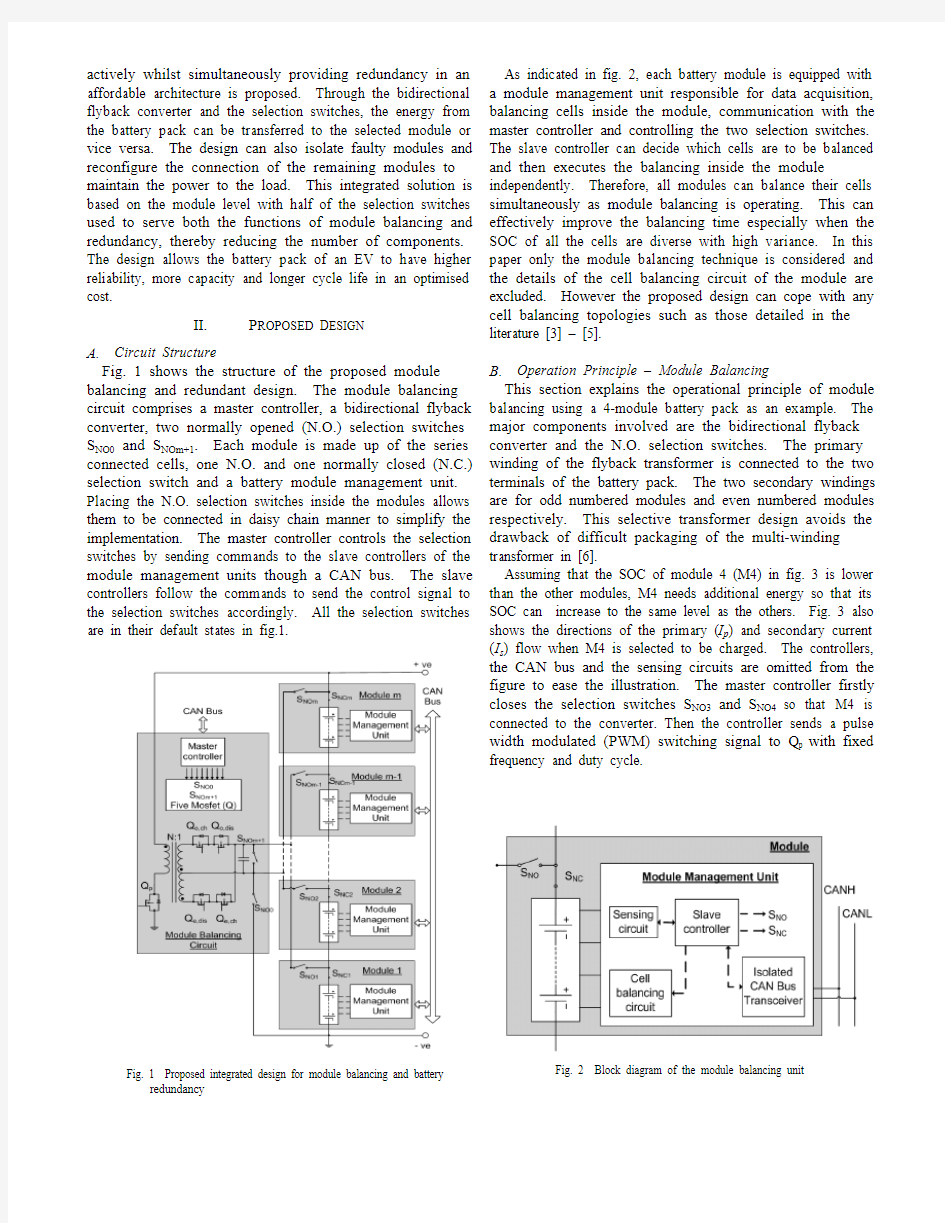
As indicated in fig. 2, each battery module is equipped with a module management unit responsible for data acquisition, balancing cells inside the module, communication with the master controller and controlling the two selection switches. The slave controller can decide which cells are to be balanced and then executes the balancing inside the module independently. Therefore, all modules can balance their cells simultaneously as module balancing is operating. This can effectively improve the balancing time especially when the SOC of all the cells are diverse with high variance. In this paper only the module balancing technique is considered and the details of the cell balancing circuit of the module are excluded. However the proposed design can cope with any cell balancing topologies such as those detailed in the literature [3] – [5]. B. Operation Principle – Module Balancing This section explains the operational principle of module balancing using a 4-module battery pack as an example. The major components involved are the bidirectional flyback converter and the N.O. selection switches. The primary winding of the flyback transformer is connected to the two terminals of the battery pack. The two secondary windings are for odd numbered modules and even numbered modules respectively. This selective transformer design avoids the drawback of difficult packaging of the multi-winding transformer in [6]. Assuming that the SOC of module 4 (M4) in fig. 3 is lower than the other modules, M4 needs additional energy so that its SOC can increase to the same level as the others. Fig. 3 also shows the directions of the primary (Ip) and secondary current (Is) flow when M4 is selected to be charged. The controllers, the CAN bus and the sensing circuits are omitted from the figure to ease the illustration. The master controller firstly closes the selection switches SNO3 and SNO4 so that M4 is connected to the converter. Then the controller sends a pulse width modulated (PWM) switching signal to Qp with fixed frequency and duty cycle.
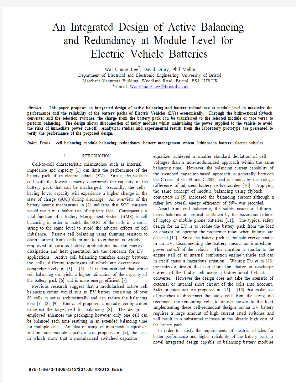
A. Circuit Structure Fig. 1 shows the structure of the proposed module balancing and redundant design. The module balancing circuit comprises a master controller, a bidirectional flyback converter, two normally opened (N.O.) selection switches SNO0 and SNOm+1. Each module is made up of the series connected cells, one N.O. and one normally closed (N.C.) selection switch and a battery module management unit. Placing the N.O. selection switches inside the modules allows them to be connected in daisy chain manner to simplify the implementation. The master controller controls the selection switches by sending commands to the slave controllers of the module management units though a CAN bus. The slave controllers follow the commands to send the control signal to the selection switches accordingly. All the selection switches are in their default states in fig.1.
Fig. 1 Proposed integrated design for module balancing and battery redundancy
Fig. 2 Block diagram of the module balancing unit
Fig. 3 Directions of the balancing currents when module M4’s SOC is low
Fig. 4 Directions of discharge current when module M2 is failed
Fig. 5 Directions of discharge current when module M1 and M2 are failed
On the secondary side, the mosfet Qe,ch will be set to remain on so that Is can flow through it and the body diode of Qe,dis. The net current flowing through the selected module and the remaining modules is ‘Is – Ip’ and ‘Ip’ respectively (Is > Ip). Thereby the SOC of M4 will increase after a certain time of balancing. On the contrary, if the SOC of M4 is higher than the other modules, the two current flows will be reverse to remove charge from M4 and to transfer it into M1 – M3. SNO3 and SNO4 are closed again while PWM signal is sent to mosfet Qe,dis this time. The body diodes of Qp and Qe,ch will be forward biased and conduct Ip and Is respectively. In the case of an odd numbered module, the operation is identical except that the mosfets Qo,ch and Qo,dis are controlled, and the secondary current will flow through the upper secondary winding of the flyback transformer. C. Operation Principle – Battery Redundancy For a battery pack consisting of m modules connected in series, the kth module can be disconnected from the pack by opening the kth NC selection switch, SNCk. To maintain the power supplied to the load, a new path is provided for the discharge current by closing the N.O. selection switches SNOm+1, SNOk and SNOk-1. The example in fig. 4 shows how the module M2 is disconnected and the remaining modules are reconnected by changing the states of SNC2, SNO5, SNO2, and SNO1. This reconfiguration prevents further deterioration of the faulty cells in M2 and allows other healthy battery modules to continue to power the electric vehicle. If the module is disconnected simply due to individual cells having very low SOC, the associated cell balancing circuit can perform the charge equalization independently and the module can be back online after equalization by setting the selection switches to the default states. Disconnecting more adjacent modules is feasible when there are more modules with failed cells. Fig. 5 shows how the reconfiguration of the circuit when both M1 and M2 have
failed cells. SNC1 and SNC2 are opened and SNO0 and SNO2 are closed by the controller. If there are more modules to be disconnected, the remaining healthy modules may not be capable of powering the vehicle. However in this scenario, the proposed design is still better than the current nonredundant designs in terms of safety since the reconnected healthy modules can support the power consumption of safety related auxiliaries such as vehicle control system, thermal management system and hazard warning flashers. III. ANALYTICAL RESULTS This section analytically illustrates how module balancing can improve the discharge capacity of the battery cells. To simplify the analysis, it is assumed that all the cells (healthy cells) in the series connected battery modules have the rated capacity (Ch) except that the cells (defective cells) in one module have a lower capacity (Cd). The SOC of any ith healthy or defective cell after discharging a capacity of, to the load from time t0 to t can be expressed as:
1
Discharging at a constant current I for a period of ?t, the discharge capacity will be simply equal to:
? 2
In the first case, a balancing circuit employing the same selective flyback converter topology but at a cell level is used. Only one defective cell can be selected for balancing each time. During the same discharge event, one defective cell is balanced for a time interval of ?tcb, the SOC of this cell after balancing is:
1 · 3
,
,
Ip,cb and Is,cb are the average primary and secondary current of the cell balancing circuit and are assumed to be constant. When there is more than one defective cell, each defective cell will accept a charge of (?tcb· Ip,cb) when another defective cell is being balanced for the same length of interval ?tcb. If there are j defective cells in total, the SOC of any defective cell is:
1 · · 4
Fig. 6 Improvement of DOD by module balancing
,
,
The total balancing time for j defective cells is j · ?tcb Consider the efficiency of the flyback converter charging the unbalanced cell is ηch, then the relationship of the input and output power is:
·
,
·
·
,
5
Vcell is the terminal voltage of the cell being balanced and Vpack is the total voltage of all the cells. Assuming that there are n cells in total and Vpack ≈ n·Vcell, Ip,cb can then be expressed in terms of Is:
, ,
·
6
By substituting (2) and (6) into (4), SOCd(t) can be expressed as a function of the discharge current I, secondary balancing current Is,cb, discharge time ?t and total cell balancing time j · ?tcb. If the discharge current and the balancing current are represented in C-rate with respect to Ch, the SOC of the defective cells at different point of time or discharge capacity can be determined accordingly. In the second case considered, module balancing is operated with secondary current Ip and Is. If all the defective cells are in one module, the SOC of the defective cells and healthy cells will be:
1 · 7
that there are 8 defective cells in one module and the capacities of them are just 90% of the healthy cells in the other modules, the discharge capacity will be determined by the capacity of the defective cells i.e. 90% of Ch Using the equations (2), (4) and (6) – (8), the SOC of the defective cells against discharge capacity (with respect to Ch) under the two balancing schemes are simulated and plotted in fig.6. Cell balancing and module balancing started when 20% of the capacity has been discharged. In the two balancing cases, both the secondary current Is,cb and Is are equal to Ch/9 and the efficiency ηch of the converter is 80%. With cell balancing only, the discharge capacity can only be increased to 90.9% before the defective cells reach 0% SOC whereas module balancing improves the discharge capacity to 97.7%. The proposed balancing scheme is effective in allowing a more utilization of the capacity and that the influence of the defective cells to the overall performance of the battery can be minimized. IV. EXPERIMENTAL RESULTS
where ?tmb is the time interval for module balancing. Similarly the primary current for the m-module battery pack is:
· 8
Consider a battery pack consists of 12 modules and each module has 8 cells in series and all the cells are discharged at a rate of 1C from fully charged state until the first cell is fully discharged. If the capacities of all the cells equal the rated capacity, the discharge capacity will be equal to Ch. However, assuming
A. Prototype Development The prototypes of the module balancing circuit and battery module management units were built and used to demonstrate the functions of module balancing and redundancy of the proposed design for six serially connected battery modules. The experiment setup and the prototypes are shown in fig. 7 and fig. 8. Each battery module consists of four Li-polymer cells connected in series therefore the battery pack has twenty four cells in total. The Li-polymer cells with a rated capacity of 1250mAh and 1130mAh are selected to represent the healthy cells and the defective cells respectively. This emulates the situation that the defective cells are approximately 10% capacity lower than the healthy cells. Each battery module is equipped with a module management unit that is designed based on the architecture described in Section II. The major components of the module management unit include a microcontroller, a battery cell monitoring integrated circuit (LTC6803), a digital isolators, a CAN transceiver and two electromechanical relays as the selection switches. Connections of digital I/O pins and communication channel are available as well for the cell balancing circuits, which were not implemented in the experiment of this paper.
Electronic load
Host computer
Six battery modules
Modu management ules circuit Fig. 7 Experiment setup
Fig. 8 Li-Polymer cells (left), module manage ement unit (middle), module balancing circuit (right)
A module balancing circuit is also built for acquiring data t from the module management units, contro olling the selection switches and the bi-directional flyback, a communicating and with the host computer. The magnetizing inductance of the g transformer is 0.54mH and the turn rat of the primary tio winding to each secondary winding is 28:4 A graphical user 4. interface (GUI) is developed with LabVIE for display and EW logging the data such as the module and c cells voltages. The GUI also allows user to manually control the function of ost module balancing and redundancy on the ho computer. B. Experiment Results of Module Balancing Six serial connected battery modules were discharge from fully charged state with a constant current of 1.25A, which is ree equivalent to 1C of the healthy cells, in thr scenarios: i) all cells in the six modules are healthy; ii) fiv modules (M1 to ve M5) consist of healthy cells and one modu (M6) consists of ule defective cells. No module balancing is pe erformed; iii) same condition as scenario ii except that mod dule balancing was applied. cuit In scenario iii, the module balancing circ was operated to charge module M6 with a secondary ba alancing current Is varying between 0.13A and 0.14A, which is approximately a f C-rate of C/10 to C/9. The efficiency of module balancing based on the measured voltage of the entir battery pack, the re voltage of M6, the primary Ip and secondary balancing current y Is was within the range of 76% to 81% in th test. he Fig. 9 shows the voltage of each mo odule with module balancing in the discharge test scenario ii The voltage of ii. module M6 in the ‘No balancing’ scenario is also plotted in o the figure for the purpose of comparison. It shows that when the discharge capacity reached 250mAh, module balancing
M6 started and the voltage of M rose because of the net discharge current (discharge cu urrent less balancing current) was lower than that in scenario ii. Since M6 was discharged o in a lower rate than the ‘No ba alancing’ case, the cells in this module can be discharged for a longer period and a higher capacity can be yielded. fference between the voltage of Fig. 9 also shows that the diff M6 and the other five healthy m modules’ in scenario iii became smaller after module balancin was activated while the ng voltages were not equal. One reason is that no module e balancing was operated from 0 to 250mAh discharge capacity, d a SOC deviation was developed between the healthy modules (M1 to M5) and the defective m module (M6). Another reason is due to the differences of the characteristics such as open al circuit voltage and the interna impedance of the two LiPolymer cell models used in the experiment. e In all three scenarios, the di ischarge ended when the cell voltage of any cell reached the cut-off voltage, 3V. Fig. 10 e compares the measured disch harge capacity in the three scenarios and the percentages are calculated with respect to rio capacity determined in scenar i. It can be shown that module balancing improved the discharge capacity by 5.4% existed in the battery pack. even one defective module e Module balancing was activated continuously after the battery d had been discharged a capacity of 250mAh (12mins) until the end of the discharge (55mins). The four defective cells in the same time for 43 minutes to in M6 were balanced at the s achieve 5.4% capacity improvement. This shows the lancing over the balancing effectiveness of module bal schemes at cell level only.
Fig. 9 Module voltages in module balancing test n
Fig. 10 Comparison of discharg capacity in scenario i, ii, iii ge
C. Experiment Results of Battery Redundancy The function of battery redundancy was tested with all six modules consisting 1250mAh cells. The voltage the battery pack was approximately 96V and one of the modules was disconnected during constant power discharge (120W). Fig.11 shows the variation of the battery pack voltage (top blue trace) and the discharge current (bottom purple trace). The time span for the selection switches to disconnect one module and reconnect the remaining modules to the load was 96ms. The battery voltage decreased to 74.6V and the discharge current increased from 1.28A to 1.57A. The circuit demonstrated the function of redundancy to disconnect a faulty module whilst maintaining power to the load. A shorter response time can be achieved if devices such as solid state relays. However, considering the high current rating for electric vehicle application, the costs of employing solid state relays would be substantially higher. Thus electromechanical relays would be more preferable for the design proposed in this paper.
associated with immediate power cut-off. Half of the selection switches serve both the functions of module balancing and redundancy to reduce the cost. The experimental results demonstrate the feasibility and the benefits of the proposed integrated design. Further investigations of how the module balancing cooperating with cell balancing circuits to achieve the optimum battery balancing performance and the reliability of the battery redundancy under varying load are necessary. REFERENCE
[1] M. Dubarry, N. Vuillaume, and B.Y. Liaw, “From Li-ion single cell model to battery pack simulation,” IEEE International Conference on Control Applications, 2008. CCA 2008, pp.708-713, 3-5 Sept. 2008 J. Vetter et al, “Ageing mechanisms in lithium-ion batteries”, Journal of Power Sources, Vol. 147, No. 1-2. (2005), pp. 269-281 Stephen W. Moore and Peter J. Schneider. "A Review of Cell Equalization Methods for Lithium Ion and Lithium Polymer Battery Systems," Proc. SAE 2001 World Congress, Detroit, MI, 2001–01– 0959, Mar. 2001 Jian Cao, N. Schofield and A. Emadi, “Battery balancing methods: A comprehensive review,” Vehicle Power and Propulsion Conference, 2008. VPPC '08. IEEE , pp.1-6, 3-5 Sept. 2008 Hong-Sun Park et al, “A Modularized Charge Equalizer for an HEV Lithium-Ion Battery String,” IEEE Trans. Industrial Electronics, , vol.56, no.5, pp.1464-1476, May 2009 M. Einhorn, W. Roessler and J. Fleig, “Improved Performance of Serially Connected Li-Ion Batteries With Active Cell Balancing in Electric Vehicles,” , IEEE Trans. Vehicular Technology, vol.60, no.6, pp.2448-2457, July 2011 W.C. Lee, D. Drury and P. Mellor, “Comparison of Passive Cell Balancing and Active Cell Balancing for Automotive Batteries,” Vehicle Power and Propulsion Conference (VPPC), 2011 IEEE , pp.17, 6-9 Sept. 2011 Chol-Ho Kim et al, “A modularized charge equalizer using battery monitoring IC for series connected Li-Ion battery strings in an electric vehicle,” 2011 IEEE 8th International Conference on Power Electronics and ECCE Asia (ICPE & ECCE), pp.304-309, May 30 2011-June 3 2011 Hong-Sun Park et al, “Design of a Charge Equalizer Based on Battery Modularization,” , IEEE Trans. Vehicular Technology, vol.58, no.7, pp.3216-3223, Sept. 2009 Zhi-Guo Kong et al, “Comparison and Evaluation of Charge Equalization Technique for Series Connected Batteries,” Power Electronics Specialists Conference, 2006. PESC '06. 37th IEEE , pp.16, 18-22 June 2006 M. Ichimura, “The safety characteristics of lithium-ion batteries for mobile phones and the nail penetration test,” Telecommunications Energy Conference, 2007. INTELEC 2007. 29th International , pp.687-692, Sept. 30 2007-Oct. 4 2007 S.M. Lukic et al, “Energy Storage Systems for Automotive Applications,” IEEE Trans. Industrial Electronics,vol.55, no.6, pp.2258-2267, June 2008 Weijing Du et al, “A novel equalization method with defectivebattery-replacing for series-connected lithium battery strings,” Energy Conversion Congress and Exposition, 2009. ECCE 2009. IEEE , pp.1806-1811, 20-24 Sept. 2009 H. Kim and K.G. Shin, “On Dynamic Reconfiguration of a LargeScale Battery System,” Real-Time and Embedded Technology and Applications Symposium, 2009. RTAS 2009. 15th IEEE , pp.87-96, 1316 April 2009 Taesic Kim, Wei Qiao and Liyan Qu, “Series-connected reconfigurable multicell battery: A novel design towards smart batteries,” Energy Conversion Congress and Exposition (ECCE), 2010 IEEE, pp.4257-4263, 12-16 Sept. 2010 A. Manenti et al, “A New BMS Architecture Based on Cell Redundancy,” , IEEE Trans. Industrial Electronics, vol.58, no.9, pp.4314-4322, Sept. 2011
[2] [3]
[4] [5]
Voltage (20V/div)
[6]
Curremt (0.5A/div)
[7]
Time (20ms/div)
[8]
Fig. 11 Battery pack voltage and discharge current in redundancy test [9]
V.
CONCLUSION
[10]
This paper proposed an integrated design providing the functions of active balancing and battery redundancy at module level in order to maximize the performance and reliability of the battery packs of Electric Vehicles (EVs) economically. The analytical result shows that without an effective balancing scheme, the discharge capacity is limited by the weak cells. To verify the functions of module balancing and battery redundancy of the proposed design, a prototype was developed and tested a Li-Polymer battery pack with six serially connected modules. In the scenario that one module regarded as defective module is 10% capacity less than the other modules, the module balancing circuit transferred charge form the battery pack to the defective module through the use of a bidirectional flyback converter and the selection switches. This improves the discharge capacity by 5.4% comparing to the case without any balancing. In the constant power discharge test, the prototype circuit successfully disconnected one module and reconnected the other modules to maintain the power delivery to the load. This improves the system reliability by avoiding risks
[11]
[12] [13]
[14]
[15]
[16]
电动自行车锂电池管理系统方案
文献综述 题目:电动自行车锂电池管理系统 前言:作为电动汽车以及混合动力汽车飞速发展的基础,电池管理系统的研究备受国内外的重视。锂电池组由于其优良的性能,在近年来得到广泛的应用。锂电池管理系统的出现,使安全高效地管理和使用锂电池组变得更加容易。本文概括地介绍了国内外锂电池管理系统领域的研究现状,并对其进行简要分析。 锂电池管理系统实现的功能包括:数据监测、荷电状态(SOC)估计、热管理、均衡管理、数据通信、数据显示与报警。其中SOC测量方法有传统的开路电压法、内阻法和安时积分法,以及新兴的模糊逻辑算法、自适应神经模糊推断算法、卡尔曼滤波估计算法、线性模型法和阻抗光谱法等。均衡管理可分为能量耗散型和能量非耗散型两大类[。 正题:美国Villanova大学和US Nanocorp公司已合作多年,对各种类型的电池SOC进行基于模糊逻辑的预测。美国约翰逊控制技术公司利用可变阻抗元
件来确定单元的温度是否超过预定门限值,时刻监控电池组温度。美国托莱多大学提出BMS基本结框图(图1)。把BMS简化成1个电子控制单元ECU和1个电荷均衡器。ECU功能有数据采集、处理、传送、控制,还控制均衡器、车载充电器等。 德国研究员认为电气控制需要实现控制制充电过程:包括均衡充电;根据SOC、电池健康状态SOH和温度来限定放电电流。电气控制中需要结合所使用的电池技术和电池类型来设定一个控制充电和放电的算法逻辑,以此作为充放电控制的标准。CAN总线是德国BOSCH公司在20世纪80年代初为解决汽车中众多的控制与测试仪器之间的数据交换而开发的一种通信协议。现已广泛用于电池管理系统。德国Kaiserse Lautern大学采用主辅模块的分布式管理结构,辅模块相当于独立式均衡器,主模块完成管理系统的功能,具有较强的均衡能力。 我国的BMS研究从开始至今,虽然相比美国、日本还差距很大,成果却也比较显著。在国家863计划2005年第一批立项研究课题中,就分别有北京理工大学承担的混合动力轿车(EQ7200HEV)用镍氢动力电池组及管理模块、苏州星恒电源有限公司承担的燃料电池轿车用高功率型锂离子动力电池组及其管理系统、北京有色金属总院承担的解放牌混合动力城市客车用锂离子电池及管理模块等课题。 近年来BMS技术发展得十分迅速,国内外的研究也是如火如荼。短短十几年时间,我国的BMS开发已初具规模。许多高校、企业都投入大量时间在BMS 的研究上,有很多方面已进入实用阶段。现在借着国家推广电动汽车的契机,更是掀起了一股研发的新浪潮。 但是与发动机技术、整车开发技术相比,现阶段的BMS技术还相当不成熟。
串联锂离子电池组的主动均衡控制研究
串联锂离子电池组的主动均衡控制研究 摘要:对于传统的主动均衡技术来说,通常情况下,存在着电量传递效率低、控制过程复杂等问题。为了彻底解决上述问题,本文结合电感、电容的电量转移技术,提出锂电池组主动均衡方法。均衡技术以boost技术和法拉电容为基础,在锂离子电池组中,可以在任何两个电池之间进行电量的传递,使得锂离子电池组在一定程度上实现电压均衡,并且可以将综合效率提高到84%,其特点主要表现为控制灵活、电量转移效率高等,静置状态下,可以进一步对大容量的串联锂电池组的电压进行均衡处理。 关键词:锂电池组主动均衡法拉电容boost 1 概述 随着人们的环保意识不断增强,人们对节能环保给予高度的关注,在这种情况下,新能源汽车逐渐成为汽车工业发展的主流趋势。而锂电池作为一项重要的因素,在一定程度上直接影响并制约着新能源汽车的推广和产业化。电池管理模块(Battery Management Module)对于电动汽车来说,是一个核心部件。在发展、推广电动汽车的过程中,电池管理技术是一项关键技术[1]。对于锂离子电池来说,凭借自身能量密度高、工作电压高等优势,进而在一定程度上广泛应用于各行各业[2]。由于锂电池的工作电压通常情况下只有
2.5~4.2V,在实际应用中,为了提高工作电压,通常情况下,需要将若干只单体锂电池进行串联处理。但是,受生产工艺的影响和制约,在容量、电压、内阻及自放电率等方面,锂电池单体之间存在一定的差异,即使电池来源于同一批次,各个电池之间同样存在一定的差异性。在实际使用过程中,正是由于电池之间存在这种差异,进而在一定程度上严重影响锂电池的使用寿命,在这种情况下,需要对串联锂电池组进行均衡管理[3]。 2 锂电池组的均衡方式 对于锂电池来说,在实际使用过程中,通常情况下,通过被动均衡、主动均衡两种方式对锂电池组进行均衡[4]。其中,在充电过程中,被动均衡方式主要是利用均衡电阻对高电压单体电池进行放电处理,使得整组电池电压在一定程度上确保一致性。对于该均衡方式方式来说,同样存在缺点,主要表现为:对能源造成浪费,该均衡方式受放电电流的影响,不能在大容量锂电池组中使用。在电量转移方面,对主动均衡方法来说,其转移方式通常情况下包括电感、电容两种。其中,Boost/buck的电感均衡是进行电感转移的基础,利用电感均衡在相邻电池之间对电量进行传递,在一定程度上通过电量传递,进一步使电量由高电压电池完成向低电压电池的转移,其电量传递效率通常高于80%。这种均衡方式同样存在弊端,主要表现为:电量传递只能发生在相邻锂电
电动自行车用铁锂电池使用说明书
使用标准:Q/HGY06-2007电动自行车用铁锂电池使用说明书 THE TECHNICAL MANUUAL OF IRON-LITHIUM BATTERY FOR ELECTRIC BICYCLE 哈尔滨光宇电源股份有限公司 HAEBIN COSLIGHT POWER CO., LTD
目录 1. 产品规格与结构 2. 磁盘性能指标 2. 产品性能 技术指标 安全性能 3. 产品使用方法 电池充电 电池放电 电池存贮与补充充电 4. 电池使用维护及注意事项 5. 质量保证
企业简介 哈尔滨光宇电源股份有限公司位于哈尔滨市开发区迎宾路集中区太南路8 号,占地面积12万平方米,建筑面积10万平方米。 公司在追求与完美品质结合的同时,一贯秉承科技创新的经营理念,凭借雄厚的经济实力和专业经验,与国内多所高校和研究机构建立了长期的合作关系,依托国内电动车市场的高速发展,率先采用国际最先进技术,自主研发出铁锂动力电池,获得多项国家专利,电池各项性能指标达到世界领先水平。光宇电源已经成为中国锂动力电池行业最具核心竞争力的企业之一。 哈尔滨光宇电源股份有限公司从日本引进全自动化锂电池生产线,主要设备包括和膏机、涂布机、辊压机、分切机、卷绕机、全自动组装一体机,充放电检测设备、激光焊接机和注夜机等相近设备。 公司先后通过ISO9001、QS9000、ISO14000和OHSA18001管理体系认证,产品通过了美国UL认证、德国T ǖV认证,有利地保证了产品从设计、制造、服务等方面均达到国际领先水平。 1. 产品规格与结构 1.1产品规格
1.2产品结构
详解动力电池组均衡设计原理及意义
详解动力电池组均衡设计原理及意义 2011-12-0619:51:36来源:互联网 分享到:标签:电池组剩余电量平衡算法 引言 随着电池作为电源使用而日益受到欢迎,又出现了一种同样强劲的需求,即最大限度地延长电池的使用寿命。电池不平衡(即组成一个电池组的各节电池的充电状态失配)在大型锂离子电池组中是个问题,这个问题是由制造工艺、工作条件和电池老化的差异造成的。不平衡可能降低电池组的总容量,并有可能损坏电池组。不平衡使电池从充电状态到放电状态都无法跟踪,而且如果没有密切监视,可能导致电池过度充电或过度放电,这将永久性地损坏电池。电池制造商按照容量和内部电阻对混合电动型汽车以及电动型汽车电池组中使用的电池进行分类,以在交付给客户的特定批次中,减少电池之间的差异。然后,再仔细挑选电池来构成汽车电池组,以改善电池组中每两节电池之间的匹配。理论上,这应该能防止电池组中产生大量的不平衡,但是尽管如此,普遍的共识是,当构成大型电池组时,既需要电池监视、又需要电池平衡,以在电池组寿命期内保持大的电池容量。 要理解平衡的重要性,第一步是利用两个相同的电池组来评估两种基本的电池管理策略。该测试将探究,在电池寿命期内,电池组的总容量是怎样受到影响的。为了评估这两种策略,要设计一个电池监视系统(BMS)。该电池监视系统由3个部分组成:监视硬件、平衡硬件和控制器。用在测试中的电池监视系统能监视电池电压和电池负载电流、平衡电池,并能控制电池与负载及电池充电器的连接。 监视硬件 一个简单的电池监视器和平衡系统如图1所示。该电池监视系统的硬件是围绕高度集成的LTC6803-1多节电池监视IC设计的。每个LTC6803-1能测量多达12节电池,并允许以可连接多个IC的串行菊花链形式连接,从而使一个系统能通过一个串行端口监视超过100个电池。当设计一个电池监视系统时,某些规范应当给以特殊考虑,首先是电池电压准确度。当试图决定单个电池的充电状态时,电池电压的准确度至关重要,而且一节电池能否在接近工作极限的条件下工作,电池电压的准确度是限制因素之一。LTC6803具 1.5mV的分辨率,准确度为 4.3mV。这将允许该控制器就电池状态做出准确决策,而不论使用的是什么样的电池化学组成。其次,电池组不平衡的一个主要来源是,电池监视电路本身的电源和备用电流的差异。在汽车应用中,备用电流尤其重要,因为大多数汽车在大部分时间里都是熄火的,这时电池监视系统处于备用模式。LTC6803仅具12uA备用电流,电流范围规定为6uA至18uA,从而可保证在一个大型电池组中,最严重的不平衡为12uA,这使每月不平衡低于10mAhr。有两个ADC输入可用来监视电池温度或其他的传感器数据。图1中显示的设计用Vtemp1输入测量电池电流。电流用LT1999测量。LT1999是一款高压双向电流检测放大器,具-5V至80V的输入范围,而且在本文所述测试情况下,设置为监视电池组高压端的±10A。LTC6803上的两个GPIO引脚用来控制一个有源负载和一个充电器。当充电结束或达到放电点时,这允许LTC6803断开电池与充电器或负载的连接。
纯电动汽车及动力电池技术发展现状
纯电动汽车及动力电池发展现状调研 一、纯电动汽车发展现状 所谓纯电动汽车,是指完全由可充电电池作为动力源、以驱动电机及其控制系统驱动行驶的汽车。纯电动汽车(BatteryElectric Vehicle,BEV)与混合动力汽车(HybridElectric Vehicle,HEV)和燃料电池汽车(Fuel CellElectric Vehicle,FEV)是目前主要的新能源汽车类型。 1.1 发展纯电动汽车的必要性 (1)促进节能减排。与传统汽车相比,纯电动汽车具有更高的能源利用效率,同时也具有二氧化碳减排的潜力。机动车污染排放是城市空气污染的主要来源之一,2013年春季北京出现多次大面积雾霾天气,机动车尾气是主要原因之一。在上海,中心城区的主要大气污染物可吸入颗粒物、氮氧化物、挥发性有机物分别有66%、90%和26%来自机动车尾气。大力推广纯电动汽车是交通领域实现低碳的最佳方案,纯电动汽车行驶过程中不产生二氧化碳,即使考虑到中国目前电力生产过程中的二氧化碳排放,纯电动汽车仍然具有13%~68%的减排能力。随着我国能源结构和电力生产方式的转变,纯电动汽车必将在未来发挥更大的减排作用。 图1.1传统汽车与纯电动汽车综合能量效率比较(单位:%) (2)降低石油对外依存度。汽车保有量的迅速增加为我国能源安全带来严峻挑战。我国汽车保有量与原油对外依存度变化趋势见图1.2。最新数据显示,截止到2012年底,中国汽车保有量已达2.4亿辆,与此相对应的是2012年中国原油对外依存度达到56.4%,创下历史新高。如果不采取措施,“十二五”中将原油依存度控制在61%的计划将很难实现。在此背景下,如何满足未来汽车的能源需求,是关系到我国能源安全的关键问题。电动汽车由于其电力来源多样化,不仅更加适合中国以煤炭为主的资源禀赋,而且能够与中国大力发展可再生能源
主动均衡和被动均衡
基本电池组设计原则: ?当第一个单电池充满电时,必须停止充电。 ?当第一个单电池无电时,放电必须终止。 ?弱蓄电池节比强蓄电池老化得更快。 ?弱蓄程度最高的电池节将最终限制电池组的可用电量(最弱环节)。 ?电池组中的系统温度梯度使运行在较高平均温度的电池节变弱。 ?在不使用均衡的情况下,在每个充放电周期中,最弱蓄和最强蓄单电池之间的电压差将增加。最终,其中一个单电将始终接近最大电压,而另外一个单电池接近最低电压→从而阻碍了电池组的充放电能力。 由于这些电池再也不会像它们最初使用时那么相互匹配,而且由于我的安装方式将使它们处于不同的温度环境中,我必须做好单电池均衡。 锂离子电池主要出现两种不匹配;充电不匹配和容量不匹配(请见图2)。充电不匹配在容量相同的单电池所容纳的充电量逐渐差生差别时出现。容量不匹配出现在同时使用初始容量不同的电池节时。由于电池组通常由几乎在同一时间生产的单电池组装而成,这些单电池的制造工艺也相差无几,所以单电池通常情况下匹配良好,只有充电普匹配会比较常见。然而,如果电池组由来源不明的单电池组装而成,或者在制造工艺方面差别很大的话,也有可能出现容量不匹配。 主要有两种电池均衡:被动均衡和主动均衡。这里列出了基本功能和它们各自的优缺点: 被动均衡: ?实现简单(硬件和软件) ?廉价 ?降低了充电不匹配 ?小均衡电流(小于1A) ?发热-浪费电能! 主动均衡:
?效率更高 ?增加可用容量 ?减少充电和容量不匹配效应 ?更快的电池组充电时间 ?可在充电和放电过程中工作 ?较大的均衡电流(大于1A),以快速均衡大电池 ?更长的电池组使用寿命 ?混用/匹配全新/旧模块 ?可使用模块内的不匹配单电池(增加产量) ?看起来主动均衡才是正道! 我决定使用手边的最积极主动的TI BMS。为了确保我始终能够从电池组获得最大电量,所有单电池之间的电压差保持在毫伏以内。由TI EM1401EVM电路板管理的电池使用全部TI部件来提供5A主动电池均衡(我设计的工作方式)。 图3显示了基本架构。其中一个BMS电路板被安装在电池节旁边,管理每个模块或电池组。 下面是这一车辆的主要技术规格:
铅酸电池、锂电池等各种电动车电池优缺点分析
目前市场上电动自行车使用的电池品种很多。除了使用量最大的阀控密封式铅酸蓄电池以外,还有镍氢电池、镍镉电池、锂离子电池、锌空电池等等。这些蓄电池都具有各自独特的优点,以下我们就来分别认识一下各电池的特性与功用。 铅酸电池 其中,以铅酸蓄电池为数量最多。铅酸蓄电池的价格最低,也最常用,中国是全世界铅酸蓄电池最大的生产国。其含污染的成分比较少,可回收性好。缺点是比容小。也就是说,在同样的容量下,电池重量和体积都大。目前的铅酸蓄电池基本上是由浮充类型的电池发展而来的。浮充电池不适应快速充电和大电流放电,虽然技术人员的花费了大量的心血进行了卓有成效的改进,可以进入实用了,但是其寿命还是非常不理想的。胶体电池 胶体电池属于铅酸蓄电池的一种发展分类,最简单的做法,是在硫酸中添加胶凝剂,使硫酸电液变为胶态。电液呈胶态的电池通常称之为胶体电池。广义而言,胶体电池与常规铅酸电池的区别不仅仅在于电液改为胶凝状。例如非凝固态的水性胶体,从电化学分类结构和特性看同属胶体电池。又如在板栅中结附高分子材料,俗称陶瓷板栅,亦可视作胶体电池的应用特色。近期已有实验室在极板配方中添加一种靶向偶联剂,大大提高了极板活性物质的反应利用率,据非公开资料表明可达到70wh/kg的重量比能量水平,这些都是现阶段工业实践及有待工业化的胶体电池的应用范例。 胶体电池与常规铅酸电池的区别,从最初理解的电解质胶凝,进一步发展至电解质基础结构的电化学特性研究,以及在板栅和活性物质中的应用推广。其最重要的特点为:用较小的工业代价,沿已有150年历史的铅酸电池工业路子制造出更优质的电池,其放电曲线平直,拐点高,比能量特别是比功率要比常规铅酸电池大20%以上,寿命一般也比常规铅酸电池长一倍左右,高温及低温特性要好得多。 镍氢电池 镍氢电池的比容比铅酸蓄电池好很多,单体电池的寿命也比较好,其大电流充放电特性也比铅酸蓄电池好。问题是镍氢电池串连电池组的管理问题比较多,一旦发生过充电以后,就会形成单体电池隔板熔化的问题,导致整组电池迅速失效。所以,国产的镍氢电池的关键技术问题还是充电器和电池管理系统的问题,而这个问题还没有引起各个电池制造商和车厂足够的重视。所以,镍氢电池的发展收到很大的制约。镍镉电池镍镉电池的大电流特性比镍氢电池好,其抗过充电特性也比镍氢电池好,中国又是世界上镍镉电池的生产大国。一些人提出镉污染的问题,中国现在还在大量的向欧洲出口镍镉电池及其应用产品,欧洲到2006年才开始限制。据中央电视台播放的消息,神州五号还是采用镍镉电池的。这是其相对比较高的可靠性的优点使该品种电池还在应用与宇航设备上。这样看,电动自行车方面过早的使镍镉电池退出应用是否有一些过激?而镍镉电池的成本和充电器的成本都明显低于镍氢电池,只要回收处理好了,还是应该保留这个电池品种的。
电动汽车动力电池的维护与检修
电动汽车动力电池的维护与检修 王楠 摘要:主要针对电动汽车动力电池运行检修管理, 研究了电池接收检验、运行管理、日常维护、运行检测与安全管理等关键环节, 结合电池运行的技术特点, 对电池的日常检测、维护与检修等进行了分析, 分析了电池受到电压,温度以及外界因数等典型故障的原因分析及维护方法, 同时提出了提高动力电池运行与检修水平以及电动电池保养的措施。 关键词:电动汽车动力电池检测与维护 目录: 摘要 1、动力电池的检修内容 (1)电压异常(2)温度异常(3)外观异常(4)检测振动对电池的影响 2、动力电池的检测系统总成 3、动力电池的维护 (1)充电不足与过充电 (2)大电流放电与过放电 (3)要及时充电 (4)短时充电 4、如何解决电池硫化与修复仪的使用 引言:在环境污染日益加剧,能源形势日益严峻的现代生活中,电动汽车无疑以其对排碳量减少无可非议的贡献受到全球的关注。当前与电动汽车有关的研究热点很多,但电池技术无疑就是其中重之又重的一块领域。现在应用于电动汽车的电池大多为电化学电池,在电池的发展史之中,铅酸蓄电池就是最成熟的电动汽车蓄电池,动力电池在能量、安全性、使用寿命等各个方面进行一代又一代的优化,才有了今天相对较为完备的电池体系。在今年4月21日至29日的北京国际车展当中备受人瞩目的典型车型都就是新出的纯电动汽车,不管就是国内还就是国外,许多汽车厂商都推出了自己的纯电动车型。由此可见在未来的汽车发展当中电动汽车将成为未来汽车发展的主要方向,然而由于受到电池技术的影响,纯电动汽车一直难以推广到市场。本文主要就是结合电池产业的厂商,引出当下比较主流的电池技术,从中了解电动汽车动力电池的结构,并结合各电池厂商分析可以怎样改正,以及探究了电动电池的检测与维护方法。 动力电池的结构 1、电池盖 2、正极--活性物质为氧化钴锂 3、隔膜--一种特殊的复合膜 4、负极--活性物质为碳 5、有机电解液 6、电池壳 动力电池的特点 1、高能量(EV)与高功率(HEV); 2、高能量密度;
解析电动自行车锂电池组保护电路设计
解析电动自行车锂电池组保护电路设计 发表时间:2019-12-23T09:45:32.933Z 来源:《电力设备》2019年第18期作者:周长山 [导读] 摘要:锂电池具有能量密度高、使用寿命长、自放电率较小等特点,常用于储能系统,也是目前电动车行业的首选能源。 (哈尔滨光宇电源股份有限公司黑龙江哈尔滨 150078) 摘要:锂电池具有能量密度高、使用寿命长、自放电率较小等特点,常用于储能系统,也是目前电动车行业的首选能源。锂电池组由单体锂电池串联而成。由于受锂电池自身和生产加工的制约,单体锂电池存在电阻、电压、容量等方面的差异,加之电池组装顺序不同,以及产生热量后的散热速率、自放电速率的差别等,因此,加强锂电池组保护电路的研究具有重要意义。本文中,主要对锂电池组保护电路设计展开相关概述。 关键词:锂电池;电池组;保护电路 引言 锂离子电池是目前已经商业化应用的电池中比能量最高的品种,因此在电动车设计中被广泛关注。现有的电池设计和制造技术难以保持电池单体参数的一致性,在实际装车使用时,由于安装位置的不同、散热状况的差别、周围环境的变化等因素,一定程度上使得电池参数的不一致性更加显著,这些参数差异会导致一个电池组内各电池单体间的不均衡问题,使其具有不同的荷电状态和端电压,严重降低电池组性能,甚至产生安全隐患。 1锂电池和电池组建模 针对锂电池管理研究,首先要明确锂离子电池的动态和静态特性。电池和电池组建模仿真能够反映电池充放电特性,是开展机理研究的重要手段。 1.1锂电池模型 锂电池模型通过电池电压、温度等可测量参数对电池的内部性能进行描述,并对参数变化进行预测。常用的锂电池模型包括电化学模型、数学模型和等效电路模型。 电化学模型是根据电池内部化学反应过程构建模型。从电化学原理出发,准确模拟电池内部电离子的传输、扩散、电化学反应、热力学现象,描述电池离子浓度的分布梯度,分析电池衰减机制和健康状态。电化学模型通常由多个偏微分方程构成,模型较复杂。 数学模型是依据实验数据,运用经验公式和数理方法建立电池经验模型,从理论上分析锂电池的一般规律。常用的数学模型有Kinetic 模型和离散马尔科夫链电池模型,但都仅关注电池外特征,难以描述电池机理过程和电池的电压?电流外特征。 等效电路模型是采用电容、电阻等电子元器件搭建电池模型,描述充放电过程中电池特性,能够较好地反映电池的动态特性,常用于电池荷电状态估算。等效电路模型具有简单直观、精度较高、计算量较小的优点。常用的等效电路模型有Rint模型、Thevenin模型、PNGV 模型。Rint模型简单,但忽略了温度、电解液浓度等因素对电池特性的影响。Thevenin模型考虑温度、电流倍率的影响,模型参数容易辨识,具有一定的动态和静态性能,但无法同时描述电池充放电过程中内部电解液发生的浓度差和电化学两种极化现象,且不能准确描述电池实时动态。在Thevenin模型基础上,增加一组RC回路,组成二阶RC等效电路模型,能兼顾电池的稳态特性和暂态特性,但无法排除自放电和温度的影响。PNGV模型则能很好地体现电池动态性能。 1.2锂电池组建模 由于单体电池状态变化、电池包内温度分布情况和电池成组方式等因素都会影响电池组特性,因此电池组建模更加困难。常用的电池组模型包括神经网络模型、电化学模型和等效电路模型。 国内学者经常会根据电池的电化学特性构建电池组电化学模型,利用卡尔曼滤波和最小二乘法分别建立在线和离线参数辨识方法,并通过实验对模型进行验证。国外学者则倾向于根据统计方法搭建电池组模型,缺点是精度由电池参数辨识的准确性决定,缺乏工程验证。学者们大多将并联电池模组简化为一个大电池模型,再将大电池模型串联组成电池组模型。假设各单体电池参数完全相同,进行整体参数辨识和仿真,但是忽略了电池连接方式对电池组性能的影响,无法对电池模组中各单体电池一致性衰减过程进行准确描述。为提高模型精度,山东大学王丽梅等人进一步考虑电池连接件阻抗和极柱引出位置等影响因素,采用Thevenin模型构建电池组等效电路模型,对电池组充放电性能进行仿真,如图1所示。 图1 基于 Thevenin 模型的并联电池模组等效电路模型 针对电池组的模型构建通常简化处理,常忽略电池参数差异。在储能系统中,电池数量多,电池参数呈离散式分布,若不能充分考虑电池参数差异问题,电池组模型精度将无法满足实际应用中的设计要求。 2锂电池组均衡管理控制策略 主动型和被动型是目前锂电池均衡管理控制策略的两种主要形式。被动型均衡管理控制策略也称耗散型均衡管理控制策略,在每个单体电池上并联一个可控的电阻进行分流,将容量大的电池中多余的电量以热量的形式消耗掉,从而实现整组电池电压的均衡。主动型均衡管理控制策略主要利用电路拓扑开关结构和算法进行融合,实现电量的转移,分为电量消耗型均衡管理控制策略和非电量消耗型均衡管理控制策略。电量消耗型属于电量浪费,非电量消耗型则是通过储能元件将电量多的部分传递给电量较少的电池。非电量消耗型均衡管理控
新能源车辆的动力电池组均衡管理系统的发展现状概述参考文本
新能源车辆的动力电池组均衡管理系统的发展现状概述参考文本 In The Actual Work Production Management, In Order To Ensure The Smooth Progress Of The Process, And Consider The Relationship Between Each Link, The Specific Requirements Of Each Link To Achieve Risk Control And Planning 某某管理中心 XX年XX月
新能源车辆的动力电池组均衡管理系统的发展现状概述参考文本 使用指引:此安全管理资料应用在实际工作生产管理中为了保障过程顺利推进,同时考虑各个环节之间的关系,每个环节实现的具体要求而进行的风险控制与规划,并将危害降低到最小,文档经过下载可进行自定义修改,请根据实际需求进行调整与使用。 新能源车辆的开发和研究已经是时代的主流,其中电 动汽车受到了市场越来越多的关注,在电动汽车中,电池 系统是重要组成部分,特别是锂电池在交通领域的应用, 对于减少温室气体的排放、降低大气污染以及新能源的应 用有着重要的意义。目前,电动汽车存在安全性低、寿命 段、充电时间长和使用成本高的问题,而电池管理系统作 为电池保护和管理的核心部件,作为电池和车辆管理系统 以及驾驶者沟通的桥梁,电池管理系统对于电动汽车性能 起着越来越关键的作用。本文介绍了电池组均衡管理的技 术发展历程、专利申请情况和涉及的主要申请人。 随着能源紧缺、城市环境污染的日益严重,替代石油
的新能源在车辆的开发利用被各国政府越来越重视。而动力电池是电动汽车的核心部件,目前车辆的动力电池存在能量密度低、价格高、寿命短等缺点,而锂电池在使用一段时间以后,电池单体性能差异在整个生命周期内客观存在,直接影响到动力电池组的使用寿命,为此,需要给予动力电池能源控制和管理,使得动力电池性能得到一定的提升。 目前,美国电动车公司生产的特斯拉纯高级电动汽车(Tesla)之所以取得成功,其核心技术就是优异的电池管理技术,采用了两千多块锂电池进行串并联设计,可以维持整个电池包的工作状态以及监控每个电池单元的系统来确保电池的高性能,使得车辆具备稳定的动力性能和优良的安全性能,具有快速充电技术,将充电时间缩短到合理的水平,在电动车领域突破了技术上的瓶颈,取得了成功,实现了从实验室转向批量生产,对汽车行业有着重大
锂电池组中的均衡方式介绍
郑州正方科技: 锂电池组在市场以及各个领域的应用已经屡见不鲜,给我们的生活,工业等等带来了很多的益处,当然,锂电池组在冲放电的过程中最重要的一个环节就是均衡环节,因为你需要保证锂电池组的输出以及输出合理到每一节电池,目前锂电池组最常见的两种均衡方式是耗能式均衡以及转能式均衡。 耗能式均衡顾名思义就是把锂电池组中某节电压高的电池用电阻把多余电量耗尽。这种方式的均衡的成本较低,设计也是相对简单,在锂电池组中单节锂电池之间的电压不能达到一致时能够起到一定的作用,但是相对的,这种方式的均衡也较为容易出现故障,而且均衡时锂电池所发出的温度较高。而且有一点,因为锂电池组中各个单节电池的电容都不尽相同,所以每次充电,容量较小的电池电量会很快的达到饱和,由于容量较大的电池还在充电中,容量较小的锂电池就会均衡,以类似于放电额形式去耗除电量一直循环直到大容量的电池电量饱和为止,所以大家可以想象时间久了,容量较小的电池整体性能就会大大额下降,这个就跟我们手机电池长时间用性能下降是一个道理。所以耗能式均衡存在着很大的弊端。 能量转移式均衡也很好理解,就是让电池组中能量较高额锂电池转移到能量较低的锂电池上,这种方式的均衡乍一听确实很实用,但是在实际情况下,目前的能量转移式均衡并不是很完善,因为这种方式的均衡并不能通过检测单节电池的电压来进行能量转移的,而是通过电池容量来进行能量转移的,当高能量的电池向低能量的电池转移
能量的时候,因为均衡电流以及充电电流时固定的,不可控的,所以在转移的时候,低容量的电池可能会达到过充值,锂电池保护板就会工作从而停止充电,那么整个循环就会因此终止。 纵观来讲,锂电池的均衡在目前来说还不能得到一个很好的完善,这方面的技术还有待改进!
锂电池电动自行车优缺点分析
锂电池电动自行车优缺点分析 发布:2011-08-23 | 作者: | 来源: haoxiaofeng | 查看:3799次 | 用户关 注: 锂离子电池被称为性能最为优越的可充电电池,有“终极电池”之称。相对于传统的铅酸电池以及镍氢、镉镍电池而言,锂离子电池问世的时间很短,其产业化和市场应用迄今只有十多年的时间,但却是可充电电池中发展最快的。目前,锂离子电池正处于性能不断提高、成本不断降低、应用领域快速扩大、市场份额急剧增长的阶段,并逐步取代了镍氢、镉镍等电池。随着手机、笔记本电脑、蓝牙、便携式摄像机、数码相机、MP3、MP4、PDA 锂离子电池被称为性能最为优越的可充电电池,有“终极电池”之称。相对于传统的铅酸电池以及镍氢、镉镍电池而言,锂离子电池问世的时间很短,其产业化和市场应用迄今只有十多年的时间,但却是可充电电池中发展最快的。目前,锂离子电池正处于性能不断提高、成本不断降低、应用领域快速扩大、市场份额急剧增长的阶段,并逐步取代了镍氢、镉镍等电池。 随着手机、笔记本电脑、蓝牙、便携式摄像机、数码相机、MP3、MP4、PDA 和电动工具等消费和便携式电子产品的持续走强,锂离子电池的市场需求一直保持相当高的增长速度,市场对于锂离子电池的巨大需求,以及人力、物力、财力的不断大规模投入,引导锂离子电池行业逐渐走强,进而促进了电池成本、材料、安全性、性能、电池管理系统、充电器等各方面的发展,最终使锂离子电池在电动自行车乃至电动汽车方面的应用成为可能。 宁波的电动自行车市场刮起了一股新能源风,不少品牌都推出了锂电池电动自行车。与目前广泛使用的铅酸蓄电池比,锂电池的优点在于寿命更长,重量更轻,锂电池与目前电动自行车广泛使用的铅酸蓄电池和部分使用的锂电能量电池相比,电池寿命将会延长,综合使用成本有望大幅降低。不过,价格偏高暂时阻碍了这种新能源车的推广普及。 >>>优点 寿命长重量轻体积小 昨天上午,记者走访了百丈路、三号桥附近的不少电动自行车专卖店,发现不少商家把锂电池电动车放在了最显眼的位置。 绿源专卖店里有一种外形小巧的锂电池电动自行车,重量只有16公斤左右,电池只有一本书大小,才2.5公斤重,可以放在包里拎着走,还可以用来给电脑充电,而与之马力相当的铅酸电池重量则在15公斤左右。不过,这种电动车价格比较贵,要2800多元一辆。“这种车上市才一周,价格比较高,但销量比预想的好,一周时间就卖出好几辆。”绿源电动车负责人张先生介绍,这种车采用了锂电池,充电一次可跑30公里左右。
动力电池组特性分析与均衡管理
动力电池组特性分析与均衡管理 被认为是未来汽车的电动汽车是电动源、电机和整车三大技术的结合体,电动源是电动汽车的核心部件,目前已经形成动力锂离子电池及其专用材料的开发热潮.做为一种新型的动力技术,锂电池在使用中必须串联才能达到使用电压的需要,单体性能上的参差不齐并不全是缘于电池的生产技术问题,从涂膜开始到成品要经过多道工序,即使每道工序都经过严格的检测程序,使每只电池的电压、内阻、容量一致,使用一段时间以后,也会产生差异,使得锂动力电池的使用技术问题迫在眉睫,而且必须尽快解决. 动力电池组的使用寿命受多种因素影响,如果电池组寿命低于单体平均寿命的一半以下,可以推断都是由于使用技术不当造成的,首要原因当推过充和过放导致单体电池提前失效.本文结合锂动力电池特性、电子电源、计算机控制技术研究动力电池组的使用技术,探讨动力电池组的均衡控制和管理. 1 动力电池主要性能参数 1.1 电压开路电压=电动势+电极过电位,工作电压=开路电压+电流在电池内部阻抗上产生的电压降.电动势由电极和电解质材料特性决定,电极的过电位与材料活性、荷电状态和工况有关.金属锂标准电极电位-3.05V,3V锂电池3.3~2.3V,4V锂 4.2~3.7V,5V锂4.9V~3.0V. 1.2 内阻电池在短时间内的稳态模型可以看作为一个电压源,其内部阻抗等效为电压源内阻,内阻大小决定了电池的使用效率.电池内阻包括欧姆电阻和极化电阻两部分,欧姆电阻不随激励信号频率变化,又称交流电阻,在同一充放电周期内,欧姆电阻除温升影响外变化很小.极化电阻由电池电化学特性对外部充放电表现出的抵抗反应产生,与电池荷电、充放强度、材料活性都有关.同批电池,内阻过大或过小者都不正常,内阻过小可能意味材料枝晶生长和微短路,内阻太大又可能是极板老化、活性物质丧失、容量衰减,内阻变化可以作为电池裂化的充分性参考依据之一. 1.3 温升电池温升
如何解决动力锂电池组各个单节电池的均衡问题
如何解决动力锂电池组各个单节电池的均衡问题 动力电池组是由多个单节电池串联组成的电池模块,由于电池个体之间内部特性的差异,若干次充、放电后,电池组会失衡,严重影响动力电池组的效率与安全。另外,电池组在充放电过程中的过充电、过放电、电流过大、温度过高等现象会加剧电池间特性的差异,从而引起单节锂电池之间容量、电压等性能的不平衡,最终导致电池组整体特性的急剧衰退和部分电池的加速损坏。因此在锂电池组合使用时必须要解决各个单节电池在电池组中的平衡问题。 电池组中各节电池电量的均衡可采用电阻均衡、电容均衡、变压器均衡等多种方案。由于本管理系统是针对大容量的动力锂电池组,若采用电阻均衡,均衡速度快但将会有过多的能量白白浪费掉;电容均衡虽然不额外耗能,但是均衡电流一般较小,很难胜任动力锂电池之间的均衡。故本均衡模块采用兼顾效率和速度的变压器均衡方案。在具体设计中直接采用DC/DC开关电源模块。由于开关电源模块具有功耗小、效率高、体积小、质量轻等优点,将其直接作为均衡模块使用是一个很好的选择。在具体使用时,根据检测到的各单节电池的电压值判断是否需要对电池组进行能量均衡。若需要,闭合均衡总开关K5,开关K1、K2向下打到均衡档,用电池组的整体能量对电压最低节电池进行额外的均衡充电,直到各节电池电压值的差别在系统要求范围之内。原理图如图4所示。 图4 电压采样、均衡充电原理图
电流采样的实现 电流是电池容量估计的关键参数,因此对电流采样的精度、抗干扰能力和线性度误差的要求都很高。在本设计中采用LEM公司的闭环电流传感器LTSR25-NP,如图5所示, 图5 LTSR25-NP实物图 该元件具有出色的精度、良好的线性度和最佳的反应时间。其额定电流为25A,最高可测80A的电流,满足系统设计的要求。该电流传感器可把充放电电流转换为0V~5V的电压信号,送至单片机的10位A/D转换器进行转换后可测得充放电电流,测量精度为0.2A。其工作特性曲线如图6所示。
电动自行车锂电池组保护电路设计
电动自行车锂电池组保护电路设计 近期,国家多部门联合发文对电动自行车产业进行了整改,要求电动自行车的整车重量应不大于40kg,最高车速应不高于[1]20km/h.据此标准,目前国内大多数电动自行车无法达标,而其中一大原因就是存在于动力源铅酸电池。由于此类电池的比能量较小,导致其体积和重量均较大,加上生产过程中易造成铅污染,如今已严重制约着电动自行车产业。 锂电池问世时间并不长,但由于其具有的比能量大,体积小,重量轻,循环寿命长,无记忆效应,无污染等特点[2],已成为未来电动自行车能源的新发展方向,目前国外的电动自行车已开始推广使用。锂电池工作电压在2.7~4.2V区间,可采用多节电池的串联和并联来满足电动自行车所需电压和电量的要求。锂电池的使用要求不能过充电、过放电、过电流,否则将降低电池寿命,严重时会导致电池爆炸。因此,需要设计一款专用保护电路对每节电池进行管理,以保证锂电池的正常充放电。在此完成了一款电动自行车锂电池保护电路的研究与设计。 1设计需求 单个锂电池型号为RFE-N18650,如图1所示,标称电压为3.6V.锂电池组采用4并10串的结构,如图2所示,标称电压为36V,标称容量为9Ah.该锂电池组的保护要求为:充电上限电压43V,放电截止电压27V.图1单节锂电池保护电路要能实现对每级电池的充放电保护,要求如下:(1)每级电池充电电压4.3V;(2)每级电池放电电压2.7V.锂电池组工作过程中,还需实现以下功能: (1)负载短路保护; (2)躲避电动机的瞬时启动电流; (3)锂电池组各级电压在充放电过程中能保持基本均衡。 2电路总体实现方案 锂电池组的保护电路实现方案如图3所示,由2块电路板组成。保护板1用于监视各级锂电池电压,通过保护IC产生保护信号,例如禁止充电、禁止放电等;保护板2接收来自保
特斯拉电动汽车动力电池管理系统解析
特斯拉电动汽车动力电池管理系统解析 1. Tesla目前推出了两款电动汽车,Roadster和Model S,目前我收集到的Roadster的资料较多,因此本回答重点分析的是Roadster的电池管理系统。 2. 电池管理系统(Battery Management System, BMS)的主要任务是保证电池组工作在安全区间内,提供车辆控制所需的必需信息,在出现异常时及时响应处理,并根据环境温度、电池状态及车辆需求等决定电池的充放电功率等。BMS的主要功能有电池参数监测、电池状态估计、在线故障诊断、充电控制、自动均衡、热管理等。我的主要研究方向是电池的热管理系统,因此本回答分析的是电池热管理系统(Battery Thermal Management System, BTMS). 1. 热管理系统的重要性 电池的热相关问题是决定其使用性能、安全性、寿命及使用成本的关键因素。首先,锂离子电池的温度水平直接影响其使用中的能量与功率性能。温度较低时,电池的可用容量将迅速发生衰减,在过低温度下(如低于0°C)对电池进行充电,则可能引发瞬间的电压过充现象,造成内部析锂并进而引发短路。其次,锂离子电池的热相关问题直接影响电池的安全性。生产制造环节的缺陷或使用过程中的不当操作等可能造成电池局部过热,并进而引起连锁放热反应,最终造成冒烟、起火甚至爆炸等严重的热失控事件,威胁到车辆驾乘人员的生命安全。另外,锂离子电池的工作或存放温度影响其使用寿命。电池的适宜温度约在10~30°C之间,过高或过低的温度都将引起电池寿命的较快衰减。动力电池的大型化使得其表面积与体积之比相对减小,电池内部热量不易散出,更可能出现内部温度不均、局部温升过高等问题,从而进一步加速电池衰减,缩短电池寿命,增加用户的总拥有成本。 电池热管理系统是应对电池的热相关问题,保证动力电池使用性能、安全性和寿命的关键技术之一。热管理系统的主要功能包括:1)在电池温度较高时进行有效散热,防止产生热失控事故;2)在电池温度较低时进行预热,提升电池温度,确保低温下的充电、放电性能和安全性;3)减小电池组内的温度差异,抑制局部热区的形成,防止高温位置处电池过快衰减,降低电池组整体寿命。 2. Tesla Roadster的电池热管理系统 Tesla Motors公司的Roadster纯电动汽车采用了液冷式电池热管理系统。车载电池组由6831节18650型锂离子电池组成,其中每69节并联为一组(brick),再将9组串联为一层(sheet),最后串联堆叠11层构成。电池热管理系统的冷却液为50%水与50%乙二醇混合物。
48V电动车锂电池保护板
适用范围: 13串锂电池组,额定放电电流<20A,充电电流<3A 特点 ■高精度电压检测电路 ■低静态功耗 ■低温度系数 ■强抗干扰能力 一、主要技术参数 二、保护板功能说明 1、将锂电池与保护板按接线图连接 保护电路分别检测串联电池组中每只电池的电压和电流,控制电池组的充放电 过程。电池组中每只电池的电压均在过充检测电压和过放检测电压之间,并且
输出无短路现象时,MOS管导通,通P+、P-可对电池组进行放电操作; 2、电池组过放保护功能 串联电池组中的任意一只电池的电压下降到过放检测电压并且达到过放延时时 间时,过放保护功能启动,切断放电MOS管,禁止电池组对外输出电流,保护电 池组安全,电路板进入休眠状态,电路板消耗电流为休眠电流以下,进入休眠状 态的电路只有在连接充电器后,并且电池电压超过过放恢复电压后才能恢复; 3、电池组过充保护功能 通过P+和C-对电池组充电过程中,当任何一节电池电压上升到电池过充检测电 压,并且超过过充延时时间时,过充保护功能启动,切断充电MOS管,禁止对电 池组充电,保护电池组安全,当电池组连接负载放电或者电池电压下降到过充恢 复电压以下时,过充状态被恢复; 4、电池组短路保护功能 当电池组放电端口P+和P-发生短路时,保护电路会在短路保护延时时间后,切 断放电MOS管,禁止电池组对外放电,当外部短路被移除后,电路自动恢复; 5、电池组过流保护功能 当电池组放电端口P+和P-发生过电流现象时,保护电路会在过流保护延时时间 后,切断放电MOS管,禁止电池组对外放电,当外部短路被移除后,电路自动 恢复。 6、电池组充电均衡功能 由于电池的匹配或者外界环境影响而导致电池组中每只电池电池电压产生差异 时,若串联各组之间的电池电压差异超过设置值时允许均衡电路工作,均衡在充 电过程中启动,均衡电阻对相对容量最高的电池组进行放电,均衡电流为均衡吸 收电流值,以此来降低电池组电压上升速度,当串联各组电池电压差异小于设置 值时时,禁止均衡电路工作,无任何均衡电
电动汽车动力电池研究综述
目录 1引言 (2) 2电动汽车对动力电池的发展及要求3? 2.1动力电池的发展 (3) 2.2?电动汽车对动力电池的要求 ............................................................. 43?铅蓄电池?4 3.1铅蓄电池工作原理 (4) 3.2铅蓄电池性能特点 (5) 3.3铅蓄电池应用范围5? 4?镍氢电池........................................................................................................... 6 4.1?镍氢电池工作原理 (6) 4.2镍氢电池性能特点.......................................................................... 6 4.3?镍氢电池应用范围 (7) 5?锂离子电池7? 5.1?锂离子电池工作原理?错误!未定义书签。 5.2?锂离子电池性能特点7? 5.3锂离子电池应用范围8? 6?电动汽车动力电池发展趋势?8 6.1铅蓄电池发展趋势.......................................................................... 8 6.2?镍氢电池发展趋势 (9) 6.3?锂离子电池发展趋势 ......................................................................... 9 7?结论................................................................................................................. 10参考文献11? ? 电动汽车动力电池研究综述