太阳能电池光电转换效率汇总
SHORT COMMUNICATION
Research
Solar Cell Ef?ciency Tables
(Version34)
Martin A.Green1*,y,Keith Emery2,Yoshihiro Hishikawa3and Wilhelm Warta4
1ARC Photovoltaics Centre of Excellence,University of New South Wales,Sydney,2052,Australia
2National Renewable Energy Laboratory,1617Cole Boulevard,Golden,CO.,80401,USA
3National Institute of Advanced Industrial Science and Technology(AIST),Research Center for Photovoltaics(RCPV),Central2,Umezono1-1-1,Tsukuba, Ibaraki,305-8568,Japan
4Fraunhofer-Institute for Solar Energy Systems,Department:Solar Cells—Materials and Technology,Heidenhofstr.2;D-79110Freiburg,Germany Consolidated tables showing an extensive listing of the highest independently con?rmed ef?ciencies for solar cells and modules are presented.Guidelines for inclusion of results into these tables are outlined and new entries since January,2009are reviewed.Copyright#2009John Wiley&Sons,Ltd.
key words:solar cell ef?ciency;photovoltaic ef?ciency;energy conversion ef?ciency
Received7May2009
INTRODUCTION
Since January1993,‘Progress in Photovoltaics’has published six monthly listings of the highest con?rmed ef?ciencies for a range of photovoltaic cell and module technologies.1,2By providing guidelines for the inclu-sion of results into these tables,this not only provides an authoritative summary of the current state of the art but also encourages researchers to seek independent con?rmation of results and to report results on a standardised basis.In the previous version of these Tables(Version33)2,results were updated to the new internationally accepted reference spectrum(IEC 60904-3,Ed.2,2008),where this was possible.
The most important criterion for inclusion of results into the tables is that they must have been measured by a recognised test centre listed elsewhere.2A distinction is made between three different eligible areas:total area;aperture area and designated illumination area1.‘Active area’ef?ciencies are not included.There are also certain minimum values of the area sought for the different device types(above0á05cm2for a concen-trator cell,1cm2for a one-sun cell,and800cm2for a module)1.
Results are reported for cells and modules made from different semiconductors and for sub-categories within each semiconductor grouping(e.g.crystalline, polycrystalline and thin?lm).
NEW RESULTS
Highest con?rmed cell and module results are reported in Tables I,II and IV.Any changes in the tables from those previously published2are set in bold type.In most cases,a literature reference is provided that describes either the result reported or a similar result. Table I summarises the best measurements for cells and submodules,Table II shows the best results for modules and Table IV shows the best results for concentrator cells and concentrator modules.Table III contains what might be described as‘notable excep-tions’.While not conforming to the requirements to be recognised as a class record,the cells and modules in this Table have notable characteristics that will be of interest to sections of the photovoltaic community with entries based on their signi?cance and timeliness.
PROGRESS IN PHOTOVOLTAICS:RESEARCH AND APPLICATIONS
Prog.Photovolt:Res.Appl.2009;17:320–326
Published online in Wiley InterScience(https://www.360docs.net/doc/ad5254971.html,)DOI:10.1002/pip.911 *Correspondence to:Martin A.Green,ARC Photovoltaics Centre of
Excellence,University of New South Wales,Sydney,2052,Aus-
tralia.
y E-mail:m.green@https://www.360docs.net/doc/ad5254971.html,.au
Copyright#2009John Wiley&Sons,Ltd.
To ensure discrimination,Table III is limited to nominally10entries with the present authors having voted for their preferences for inclusion.Readers who have suggestions of results for inclusion into this Table are welcome to contact any of the authors with full details.Suggestions conforming to the guidelines will be included on the voting list for a future issue(a smaller number of‘notable exceptions’for concen-trator cells and modules additionally is included in Table IV).
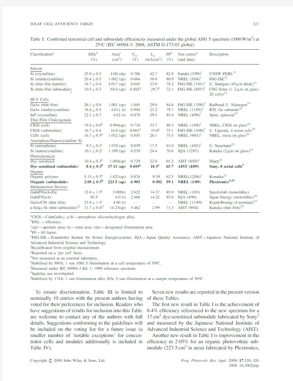
Seven new results are reported in the present version of these Tables.
The?rst new result in Table I is the achievement of 8á4%ef?ciency referenced to the new spectrum for a 17cm2dye-sensitised submodule fabricated by Sony3 and measured by the Japanese National Institute of Advanced Industrial Science and Technology(AIST). Another new result in Table I is improvement in the ef?ciency to2á05%for an organic photovoltaic sub-module(223á5cm2in area)fabricated by Plextronics,
Table I.Con?rmed terrestrial cell and submodule ef?ciencies measured under the global AM1á5spectrum(1000W/m2)at
258C(IEC60904-3:2008,ASTM G-173-03global)
Classi?cation a Ef?c b
(%)Area c
(cm2)
V oc
(V)
J sc
(mA/cm2)
FF d
(%)
Test centre e
(and date)
Description
Silicon
Si(crystalline)25á0?0á54á00(da)0á70642á782á8Sandia(3/99)f UNSW PERL11
Si(multicrystalline)20á4?0á51á002(ap)0á66438á080á9NREL(5/04)f FhG-ISE12
Si(thin?lm transfer)16á7?0á44á017(ap)0á64533á078á2FhG-ISE(7/01)f U.Stuttgart(45m m thick)13 Si(thin?lm submodule)10á5?0á394á0(ap)0á492g29á7g72á1FhG-ISE(8/07)f CSG Solar(1–2m m on glass;
20cells)14
III-V Cells
GaAs(thin?lm)26á1?0á81á001(ap)1á04529á684á6FhG-ISE(7/08)f Radboud U.Nijmegen15 GaAs(multicrystalline)18á4?0á54á011(t)0á99423á279á7NREL(11/95)f RTI,Ge substrate16
InP(crystalline)22á1?0á74á02(t)0á87829á585á4NREL(4/90)f Spire,epitaxial17
Thin Film Chalcogenide
CIGS(cell)19á4?0á6h0á994(ap)0á71633á780á3NREL(1/08)f NREL,CIGS on glass18 CIGS(submodule)16á7?0á416á0(ap)0á661g33á6g75á1FhG-ISE(3/00)f U.Uppsala,4serial cells19 CdTe(cell)16á7?0á5h1á032(ap)0á84526á175á5NREL(9/01)f NREL,mesa on glass20 Amorphous/Nanocrystalline Si
Si(amorphous)9á5?0á3i1á070(ap)0á85917á563á0NREL(4/03)f U.Neuchatel21
Si(nanocrystalline)10á1?0á2j1á199(ap)0á53924á476á6JQA(12/97)Kaneka(2m m on glass)22 Photochemical
Dye sensitised10á4?0á3k1á004(ap)0á72922á065á2AIST(8/05)f Sharp23
Dye sensitised(submodule)8á4W0á3k17á11(ap)0á693g18á3g65á7AIST(4/09)Sony,8serial cells3 Organic
Organic polymer5á15?0á3k1á021(ap)0á8769á3962á5NREL(12/06)f Konarka24
Organic(submodule)2á05W0á3k223á5(ap)6á9030á50259á1NREL(1/09)Plextronics4,25 Multijunction Devices
GaInP/GaAs/Ge32á0?1á5j3á989(t)2á62214á3785á0NREL(1/03)Spectrolab(monolithic) GaInP/GaAs30á3j4á0(t)2á48814á2285á6JQA(4/96)Japan Energy(monolithic)26 GaAs/CIS(thin?lm)25á8?1á3j4á00(t)———NREL(11/89)Kopin/Boeing(4terminal)27 a-Si/m c-Si(thin submodule)j,l11á7?0á4j,l14á23(ap)5á4622á9971á3AIST(9/04)Kaneka(thin?lm)28
a CIGS?CuInGaSe
2;a-Si?amorphous silicon/hydrogen alloy.
b Ef?c.?ef?ciency.
c(ap)?aperture area;(t)?total area;(da)?designated illumination area.
d FF??ll factor.
e FhG-ISE?Fraunhofer Institut fu¨r Solare Energiesysteme;JQA?Japan Quality Assurance;AIST?Japanese National Institute o
f Advanced Industrial Science and Technology.
f Recalibrated from original measurement.
g Reported on a‘per cell’basis.
h Not measured at an external laboratory.
i Stabilised by800h,1sun AM1á5illumination at a cell temperature of508C.
j Measured under IEC60904-3Ed.1:1989reference spectrum.
k Stability not investigated.
l Stabilised by174h,1sun illumination after20h,5sun illumination at a sample temperature of508C.
Copyright#2009John Wiley&Sons,Ltd.Prog.Photovolt:Res.Appl.2009;17:320–326
DOI:10.1002/pip SOLAR CELL EFFICIENCY TABLES321
measured by the National Renewable Energy Labora-tory(NREL)in January2009and reported by Plextronics soon after4.
A new result in Table III is achievement of23á0% ef?ciency in a large100cm2crystalline silicon cell fabricated by Sanyo using the company’s HIT cell approach(amorphous silicon/crystalline silicon het-erojunction)5and measured by AIST.
Another new result in Table III is the improvement of a small area(0á27cm2)stabilised amorphous silicon based tandem cell stack from12á1to12á5%for a device fabricated by United Solar Ovonic and
Table II.Con?rmed terrestrial module ef?ciencies measured under the global AM1á5spectrum(1000W/m2)at a cell temperature of258C(IEC60904-3:2008,ASTM G-173-03global)
Classi?cation a Ef?c.b
(%)Area c
(cm2)
V oc
(V)
I sc
(A)
FF d
(%)
Test centre
(and date)
Description
Si(crystalline)22á9?0á6778(da)5á603á9780á3Sandia(9/96)e UNSW/Gochermann29
Si(large crystalline)20á3?0á616300(ap)66á16á3578á7Sandia(8/07)e SunPower30
Si(multicrystalline)15á5?0á4f1017(ap)14á61á3778á6Sandia(10/94)e Sandia/HEM31
Si(thin-?lm polycrystalline)8á2?0á2661(ap)25á00á32068á0Sandia(7/02)e Paci?c Solar(1–2m m on glass)32 CIGSS13á5?0á73459(ap)31á22á1868á9NREL(8/02)e Showa Shell(Cd free)33
CdTe10á9?0á54874(ap)26á213á2462á3NREL(4/00)e BP Solarex34
a-Si/a-SiGe/a-SiGe(tandem)g10á4?0á5h905(ap)4á3533á28566á0NREL(10/98)e USSC35
a CIGSS?CuInGaSSe;a-Si?amorphous silicon/hydrogen alloy;a-SiGe?amorphous silicon/germanium/hydrogen alloy.
b Ef?c.?ef?ciency.
c(ap)?aperture area;(da)?designated illumination area.
d FF??ll factor.
e Recalibrated from original measurement.
f Not measured at an external laboratory.
g Light soaked at NREL for1000h at508C,nominally1-sun illumination.
h Measured under IEC60904-3Ed.1:1989reference spectrum.
Table III.‘Notable Exceptions’:‘Top ten’con?rmed cell and module results,not class records measured under the global AM1á5spectrum(1000Wmà2)at258C(IEC60904-3:2008,ASTM G-173-03global)
Classi?cation a Ef?c.b
(%)Area c
(cm2)
V oc
(V)
J sc
(mA/cm2)
FF
(%)
Test centre
(and date)
Description
Cells(silicon)
Si(MCZ crystalline)24á7?0á54á0(da)0á70442á083á5Sandia(7/99)d UNSW PERL,SEH MCZ substrate36 Si(moderate area)23á9?0á522á1(da)0á70441á981á0Sandia(8/96)d UNSW PERL,FZ substrate29
Si(large crystalline)23á0W0á6100á4(t)0á72939á680á0AIST(2/08)Sanyo HIT,n-type substrate5
Si(large crystalline)22á0?0á7147á4(t)0á67740á380á6FhG-ISE(3/06)d Sunpower n-type substrate37
Si(large multicrystalline)18á7?0á5217á4(t)0á63937á777á6AIST(2/08)d Mitsubishi Electric,honeycomb38 Cells(other)
GaInP/GaInAs/GaInAs
(tandem)
33á8?1á5e,f0á25(ap)2á96013á186á8NREL(1/07)NREL,monolithic39
CIGS(thin?lm)20á0?0á6e0á419(ap)0á69235á781á0NREL(10/07)d NREL,CIGS on glass40
a-Si/nc-Si/nc-Si(tandem)12á5W0á7g0á27(da)2á0109á1168á4NREL(3/09)United Solar stabilised6,41
Dye-sensitised11á2?0á3h0á219(ap)0á73621á072á2AIST(3/06)d Sharp42
Organic6á4W0á3h,i0á759(ap)0á58516á765á5NREL(12/08)Konarka24
a CIGS?CuInGaSe
2.
b Ef?c.?ef?ciency.
c(ap)?aperture area;(t)?total area;(da)?designated illumination area.
d Recalibrated from original measurement.
e Not measured at an external laboratory.
f Measured under IEC60904-3Ed.1:1989reference spectrum.
g Light soaked under100mW/cm2white light at508C for1000h.
h Stability not investigated.
i Light soaked under simulated AM1á5for about140hs prior to shipment to NREL.
Copyright#2009John Wiley&Sons,Ltd.Prog.Photovolt:Res.Appl.2009;17:320–326
DOI:10.1002/pip 322M.A.GREEN ET AL.
measured at NREL.This triple junction a-Si:H/nc-Si:H/nc-Si:H cell stack6gave improved current compared to the previous record a-Si:H/a-SiGe:H/a-SiGe:H device,more than offsetting a slight reduction in voltage.
Progress also continues to be made with small-area organic bulk heterojunction solar cells with the energy conversion ef?ciency increased from5á4to6á4%in three steps since the previous version of these Tables2. In a recent presentation4,Plextronics reports having a very small area cell(0á04cm2)of6á0%ef?ciency measured by the National Renewable Energy Labora-tory(NREL)in August2008(808mV,10á3mA/cm2 and71á7%for V oc,I sc and FF,respectively).In December2008,Konarka announced achievement of the6%milestone by the University of California,Santa Barbara(UCSB)and Universite′Laval7.This was for a larger but still small(0á13cm2)bulk heterojunction cell fabricated by UCSB and measured by NREL in October2008(880mV,10á6mA/cm2and64á0% for V oc,I sc and FF,respectively).The new feature of this cell was the use of a carbazole based donor polymer(PCDTBT)with PC70BM as the acceptor, together with a10nm thick TiO2hole-blocking layer as an optical spacer8.
In December2008,NREL measured a larger area (0á76cm2)cell fabricated by Konarka with6á4%ef?-ciency.The active layer consisted of a conjugated polymer/fullerene blend.Both components are pro-prietary materials.The smaller voltage and higher current density of this device as listed in Table III compared to the other6%ef?cient devices above, together with a spectral response extending beyond 800nm,suggest the use of appreciably smaller bandgap donor polymer.
Given the relatively immature state of organic cell technology,measurement results for these cells are reported before stabilisation of cell performance,in contrast to most other technologies listed.However, information has been published concerning the stabi-lity of one of the three6%organic cells above.For the carbazole-based cell,supplementary information8suggests the cell degraded1–2%relative during the week after ?rst measurement and5%relative after40days.The
Table IV.Terrestrial concentrator cell and module ef?ciencies measured under the ASTM G-173-03direct beam AM1á5
spectrum at a cell temperature of258C
Classi?cation Ef?c.a
(%)Area b
(cm2)
Intensity c
(suns)
Test centre
(and date)
Description
Single Cells
GaAs28á8W1á2f0á0504(da)232FhG-ISE(1/09)Fraunhofer ISE
Si27á6?1á0e1á00(da)92FhG-ISE(11/04)Amonix back-contact43
CIGS(thin?lm)21á8?1á5f,g0á102(da)14NREL(2/01)d NREL
Multijunction cells
GaInP/GaAs/Ge(2-terminal)40á7?2á4e0á267(da)240NREL(9/06)Spectrolab,lattice-mismatched44 GaInP/GaAs/GaInAs(2-terminal)40á8?2á4e,f0á0976(da)140NREL(7/08)NREL,inverted monolithic45 GaInP/GaInAs/Ge(2-terminal)41á1W2á5f0á0509(da)454FhG-ISE(1/09)Fraunhofer,metamorphic10 Submodules
GaInP/GaAs/Ge27á0?1á5g34(ap)10NREL(5/00)ENTECH46
Modules
Si20á5?0.f f1875(ap)79Sandia(4/89)d Sandia/UNSW/ENTECH(12cells)47‘Notable Exceptions’
GaAs/GaSb(4-terminal)32á6?1á7g0á053(da)100Sandia(10/89)d Boeing,mechanical stack48
InP/GaInAs(3-terminal)31á7?1á6f0á063(da)50NREL(8/90)d NREL,monolithic49
GaInP/GaInAs(2-terminal)30á2?1á2g0á1330(da)300NREL/FhG-ISE
(6/01)
Fraunhofer,monolithic50
GaAs(high concentration)26á6?1á00á203(da)1000Sandia(8/88)d Varian51
Si(large area)21á7?0á720á0(da)11Sandia(9/90)d UNSW laser grooved52
a Ef?c.?ef?ciency.
b(da)?designated illumination area;(ap)?aperture area.
c One sun corresponds to direct irradiance of1000Wmà2.
d Recalibrated from original measurement.
e Measured under a low aerosol optical depth spectrum similar to ASTM G-173-03direct53.
f Not measured at an external laboratory.
g Measured under old ASTM E891-87reference spectrum.
Copyright#2009John Wiley&Sons,Ltd.Prog.Photovolt:Res.Appl.2009;17:320–326
DOI:10.1002/pip SOLAR CELL EFFICIENCY TABLES323
cell was encapsulated using a glass front cover and a UV-curing expoxy on the rear and appears to have been unilluminated in air for most of this period.A good review of the stability of present and past organic cells has been published elsewhere9.
Concentrator cell and module results(Table IV)are now referenced against the direct normal spectrum tabulated in ASTM G173-03(except where otherwise noted).Two new results are reported.One is an increase in the ef?ciency of a GaAs concentrator cell to 28á8%as measured under the new reference spectrum. The cell was both fabricated and measured by the Fraunhofer Institute for Solar Energy Systems(FhG-ISE).The cell maintained the measured ef?ciency over the152–232suns concentration range(more precisely, 152–232kW/m2direct irradiance range).
A further signi?cant new result in Table IV has been a new overall record for cell performance under con-centrated sunlight.An ef?ciency of41á1%is reported10 for a metamorphic(non-lattice-matched)Ga0á35In0á65P/ Ga0á83In0á17As/Ge cell fabricated and measured by FhG-ISE under the new reference spectrum.This cell maintained this ef?ciency over the411–454suns concentration range.Parameters at454suns were 2á867V,0á3805A and87á2%for V oc,I sc and FF, respectively.An ef?ciency of40á4%was measured even at880suns concentration.Also shown in Table IV are other recent concentrator cells of comparable ef?ciency as fabricated by two other groups,with all three results close to equivalent given the measurement uncertainties.Note that the40á7%cell fabricated by Spectrolab and measured by NREL in September2006 is the highest ef?ciency device that has been fully independently con?rmed.
DISCLAIMER
While the information provided in the tables is provided in good faith,the authors,editors and publishers cannot accept direct responsibility for any errors or omissions.
REFERENCES
1.Green MA,Emery K,King DL,Igari S.Solar cell
ef?ciency tables(version15).Progress in Photovoltaics: Research and Applications2000;8:187–196.
2.Green MA,Emery K,Hishikawa Y,Warta W.Solar cell
ef?ciency tables(version33).Progress in Photovoltaics: Research and Applications2009;17:85–94.
3.Morooka M,Noda K.Development of dye-sensitized
solar cells and next generation energy devices.
88th Spring Meeting of The Chemical Society of Japan Tokyo,26March2008.
4.Tipnis R.‘‘Printed Solar Power:From Lab to Market’’,
Nortech Advanced Energy Speaker Series,February3, 2009(available at https://www.360docs.net/doc/ad5254971.html,/Docs/ Ritesh%20Tipnis%20Plextronics.pdf).
5.Maruyama E,Terakawa A,Taguchi M,Yoshimine Y,Ide
D,Baba T,Shima M,Sakata H,Tanaka M.Sanyo’s challenges to the development of high-ef?ciency HIT solar cells and the expansion of HIT business,4th World Conference on Photovoltaic Energy Conversion (WCEP-4),Hawaii,May,2006.
6.Yan B,Yue G,Guha S.‘‘Status of nc-Si:H Solar Cells at
United Solar and Roadmap for Manufacturing a-Si:H and nc-Si:H Based Solar Panels’’in‘‘Amorphous and Polycrystalline Thin-Film Silicon Science and Technol-ogy2007’’,edited by V.Chu,S.Miyazaki,A.Nathan,J.
Yang,H-W.Zan(Materials Research Society Sym-posium Proceeding,V ol.989,Warrendale,PA,2007), Paper#:0989-A15-01.
7.Press release,Konarka,December9,2009.
8.Park SH,Roy A,Beaupre S,Cho S,Coates N,Moon JS,
Moses D,Leclerc M,Lee K,Heeger AJ.Bulk hetero-junction solar cells with internal quantum ef?ciency approaching100%.Nature Photonics2009;3:297–303.
9.Jorgensen M,Norrman K,Krebs FC.Stability/Degra-
dation of polymer solar cells.Solar Energy Materials and Solar Cells2008;92:686–714.
10.http://www.ise.fraunhofer.de/press-and-media/press-
releases/press-releases-2009/world-record-41.1-ef?ciency-reached-for-multi-junction-solar-cells-at-fraunhofer-ise. 11.Zhao J,Wang A,Green MA,Ferrazza F.Novel19.8%
ef?cient‘‘honeycomb’’textured multicrystalline and
24.4%monocrystalline silicon solar cells.Applied Phy-
sics Letters1998;73:1991–1993.
12.Schultz O,Glunz SW,Willeke GP.Multicrystalline
silicon solar cells exceeding20%ef?ciency.Progress in Photovoltaics:Research and Applications2004;12: 553–558.
13.Bergmann RB,Rinke TJ,Berge C,Schmidt J,Werner
JH.Advances in monocrystalline Si thin-?lm solar cells by layer transfer Technical Digest,PVSEC-12June, 2001,Chefju Island,Korea,11–15.
14.Keevers MJ,Young TL,Schubert U,Green MA.10%
Ef?cient CSG Minimodules,22nd European Photovol-taic Solar Energy Conference,Milan,September2007.
15.Bauhuis GJ,Mulder P,Schermer JJ,HaverKamp EJ,van
Deelen J,Larsen PK.High ef?ciency thin?lm GaAs solar cells with improved radiation hardness, 20th European Photovoltaic Solar Energy Conference, Barcelona,June,2005;468–471.
16.Venkatasubramanian R,O’Quinn BC,Hills JS,Sharps
PR,Timmons ML,Hutchby JA,Field H,Ahrenkiel A,
Copyright#2009John Wiley&Sons,Ltd.Prog.Photovolt:Res.Appl.2009;17:320–326
DOI:10.1002/pip 324M.A.GREEN ET AL.
Keyes B.18.2%(AM1.5)ef?cient GaAs solar cell on optical-grade polycrystalline Ge substrate,Conference Record,25th IEEE Photovoltaic Specialists Conference Washington,May1997,31–36.
17.Keavney CJ,Haven VE,Vernon SM.Emitter structures
in MOCVD InP solar cells Conference Record,21st IEEE Photovoltaic Specialists Conference Kissimimee,May, 1990,141–144.
18.Repins I,Contreras M,Romero Y,Yan Y,Metzger W,Li
J,Johnston S,Egaas B,DeHart C,Scharf J,McCandless BE,Nou?R.‘‘Characterization of19.9%-ef?cienct CIGS Absorbers’’,IEEE Photovoltaics Specialists Con-ference Record2008;33.
19.Kessler J,Bodegard M,Hedstrom J,Stolt L.New world
record Cu(In,Ga)Se2based mini-module:16.6% Proceedings,16th European Photovoltaic Solar Energy Conference Glasgow,2000,2057–2060.
20.Wu X,Keane JC,Dhere RG,DeHart C,Duda A,Gessert
TA,Asher S,Levi DH,Sheldon P.16.5%-ef?cient CdS/ CdTe polycrystalline thin-?lm solar cell Conf.Proceed-ings,17th European Photovoltaic Solar Energy Con-ference Munich,22–26October2001,995–1000. 21.Meier J,Sitznagel J,Kroll U,Bucher C,Fay S,Moriarty
T,Shah A.Potential of amorphous and microcrystalline silicon solar cells.Thin Solid Films2004;451–452:518–524.
22.Yamamoto K,Toshimi M,Suzuki T,Tawada Y,Okamoto
T,Nakajima A.Thin?lm poly-Si solar cell on glass substrate fabricated at low temperature MRS Spring Meeting April,1998,San Francisco.
23.Chiba Y,Islam A,Kakutani K,Komiya R,Koide N,Han
L.High ef?ciency dye sensitized solar cells Technical Digest,15th International Photovoltaic Science and Engineering Conference Shanghai,October,2005, 665–666.
24.See https://www.360docs.net/doc/ad5254971.html,.
https://www.360docs.net/doc/ad5254971.html,ird D,Vaidya S,Li S,Mathai M,Woodworth B,Sheina
E,Williams S,Hammond T.‘‘Advances in Plexcore TM active layer technology systems for organic photovoltaics: Roof-top and accelerated lifetime analysis of high per-formance organic photovoltaic cells’’2007,SPIE Proc., V ol.6656,No.12.
26.Ohmori M,Takamoto T,Ikeda E,Kurita H.High ef?-
ciency InGaP/GaAs tandem solar cells Tech.Digest, International PVSEC-9Miyasaki,Japan,November, 1996,525–528.
27.Mitchell K,Eberspacher C,Ermer J,Pier D.Single
and tandem junction CuInSe2cell and module technol-ogy Conf.Record,20th IEEE Photovoltaic Specialists Conference Las Vegas,September,1988,1384–1389.
28.Yoshimi M,Sasaki T,Sawada T,Suezaki T,Meguro T,
Matsuda T,Santo K,Wadano K,Ichikawa M,Nakajima A,Yamamoto K.High ef?ciency thin?lm silicon hybrid solar cell module on1m2-class large area substrate Conf.
Record,3rd World Conference on Photovoltaic Energy Conversion Osaka,May,2003,1566–1569.
29.Zhao J,Wang A,Yun F,Zhang G,Roche DM,Wenham
SR,Green MA.20,000PERL silicon cells for the‘‘1996 World Solar Challenge’’solar car race.Progress in Photovoltaics1997;5:269–276.
30.Rose D,Koehler O,Kaminar N,Mulligan B,King D.
Mass Production of PV modules with18%total-area ef?ciency and high energy delivery per peak watt,IEEE 4th World Conference on Photovoltaic Energy Conver-sion,pp.2018–2023,May7–12,2006Waikoloa,HI.
31.King DL,Schubert WK,Hund TD.World’s?rst15%
ef?ciency multicrystalline silicon modules Conf.
Record,1st World Conference on Photovoltaic Energy Conversion Hawaii,December,1994,1660–1662. 32.Basore PA.Pilot production of thin-?lm crystalline silicon
on glass modules Conf.Record,29th IEEE Photovoltaic Specialists Conference New Orleans,May,2002,49–52.
33.Tanaka Y,Akema N,Morishita T,Okumura D,Kushiya
K.Improvement of V oc upward of600mV/cell with CIGS-based absorber prepared by Selenization/Sulfur-ization Conf.Proceedings,17th EC Photovoltaic Solar Energy Conference Munich,October,2001,989–994.
34.Cunningham D,Davies K,Grammond L,Mopas E,
O’Connor N,Rubcich M,Sadeghi M,Skinner D, Trumbly https://www.360docs.net/doc/ad5254971.html,rge area Apollo TM module performance and reliability Conf.Record,28th IEEE Photovoltaic Specialists Conference Alaska,September,2000,13–18.
35.Yang J,Banerjee A,Glatfelter T,Hoffman K,Xu X,
Guha S.Progress in triple-junction amorphous silicon-based alloy solar cells and modules using hydrogen dilution Conf.
Record,1st World Conference on Photovoltaic Energy Conversion Hawaii,December,1994,380–385.
36.Zhao J,Wang A,Green MA.24.5%ef?ciency silicon
PERT cells on MCZ substrates and24.7%ef?ciency PERL cells on FZ substrates.Progress in Photovoltaics 1999;7:471–474.
37.McIntosh K,Cudzonovic M,Smith D,Mulligan W,
Swanson R.The choice of silicon wafer for the pro-duction of rear-contact solar cells Conference.Record, 3rd World Conference on Photovoltaic Energy Conver-sion Osaka,May2003,971–974.
38.Niinobe D,Nishimura K,Matsuno S,Fujioka H,Katsura
T,Okamoto T,Ishihara T,Morikawa H,Arimoto S.
‘‘Honeycomb structured multi-crystalline silicon solar cells with18.6%ef?ciency via industrially applicable laser-process’’,23rd European Photovoltaic Solar Energy Conference and Exhibition,Valencia,Session Reference:2CV.5.74,2008.
39.Geisz J,Kurtz S,Wanlass MW,Ward JS,Duda A,
Friedman DJ,Olson JM,McMahon WE,Moriarty TE, Kiehl JT.High-ef?ciency GaInP/GaAs/InGaAs triple-junction solar cells grown inverted with a metamorphic bottom junction.Applied Physics Letters2007;91: 023502.
Copyright#2009John Wiley&Sons,Ltd.Prog.Photovolt:Res.Appl.2009;17:320–326
DOI:10.1002/pip SOLAR CELL EFFICIENCY TABLES325
40.Repins I,Contreras MA,Egaas B,DeHart C,Scharf J,
Perkins CL,To B,Nou?R.19.9%-ef?cient ZnO/CdS/ CuInGaSe2solar cell with81.2%?ll factor.Progress in Photovoltaics:Research and Applications2008;16(3): pp.235–239.
41.Yang J,Banerjee A,Sugiyama S,Guha S.Recent
progress in amorphous silicon alloy leading to13% stable cell ef?ciency Conf.Record,26th IEEE Photo-voltaic Specialists Conference Anaheim,September/ October,1997,563–568.
42.Han L,Fukui A,Fuke N,Koide N,Yamanaka R.High
ef?ciency of dye sensitized solar cell and module, 4th World Conference on Photovoltaic Energy Conver-sion(WCEP-4),Hawaii,May,2006.
43.Slade A,Garboushian V.27.6%ef?cient silicon con-
centrator cell for mass production,Technical Digest, 15th International Photovoltaic Science and Engineer-ing Conference,Shanghai,October2005;701.
44.King RR,Law DC,Edmondson KM,Fetzer CM,Kinsey
GS,Yoon H,Sherif RA,Karam NH.40%ef?cient metamorphic GaInP/GaInAs/Ge multijunction solar cells.Applied Physics Letters2007;90:183516.
45.Geisz JF,Friedman DJ,Ward JS,Duda A,Olavarria WJ,
Moriarty TE,Kiehl JT,Romero MJ,Norman AG,Jones KM.40.8%ef?cient inverted triple-junction solar cell with two independently metamorphic junctions.Applied Physics Letters2008;93:123505.
46.O’Neil MJ,McDanal AJ.Outdoor measurement of28%
ef?ciency for a mini-concentrator module,Proceedings, National Center for Photovoltaics Program Review Meeting,Denver,16–19April,2000.47.Chiang CJ,Richards EH,A20%ef?cient photovoltaic
concentrator module Conf.Record,21st IEEE Photo-voltaic Specialists Conference Kissimimee,May,1990, 861–863.
48.Fraas LM,Avery JE,Sundaram VS,Kinh VT,Davenport
TM,Yerkes JW,Gee JM,Emery KA.Over35%ef?cient GaAs/GaSb stacked concentrator cell assemblies for terrestrial applications Conf.Record,21st IEEE Photo-voltaic Specialists Conference Kissimimee,May,1990, 190–195.
49.Wanlass MW,Coutts TJ,Ward JS,Emery KA,Gessert
TA,Osterwald CR.Advanced high-ef?ciency concen-trator tandem solar cells Conf.Record,21st IEEE Photo-voltaic Specialists Conference Kissimimee,May,1990, 38–45.
50.Bett AW,Baur C,Beckert R,Diimroth F,Letay G,Hein
M,Muesel M,van Riesen S,Schubert U,Siefer G, Sulima OV,Tibbits TND.Development of high-ef?ciency mechanically stacked GaInP/GaInAs-GaSb triple-junction concentrator solar cells Conf.Record,17th European Solar Energy Conference Munich,October,2001,84–87.
51.MacMillan HF,Hamaker HC,Kaminar NR,Kuryla MS,
Ladle Ristow M,Liu DD,Virshup GF.28%ef?cient GaAs solar cells20th IEEE Photovoltaic Specialists Conference Las Vegas,September,1988,462–468. 52.Zhang F,Wenham SR,Green https://www.360docs.net/doc/ad5254971.html,rge area,concen-
trator buried contact solar cells.IEEE Transactions on Electron Devices1995;42:144–149.
53.Gueymard CA,Myers D,Emery K.Proposed reference
irradiance spectra for solar energy systems testing.Solar Energy2002;73:443–467.
Copyright#2009John Wiley&Sons,Ltd.Prog.Photovolt:Res.Appl.2009;17:320–326
DOI:10.1002/pip 326M.A.GREEN ET AL.
一文看懂光电转化效率计算方法
一文看懂光电转化效率计算方法 光电转化效率简介光电转化效率,即入射单色光子-电子转化效率(monochromaticincidentphoton-to-electronconversionefficiency,用缩写IPCE表示),定义为单位时间内外电路中产生的电子数Ne与单位时间内的入射单色光子数Np之比。 光电转化效率的公式从电流产生的过程考虑,IPCE与光捕获效率(lightharvestingefficiency)LHE(l)、电子注入量子效率finj及注入电子在纳米晶膜与导电玻璃的后接触面(backcontact)上的收集效率fc三部分相关。见公式: IPCE(l)=LHE(l)′finj′fc=LHE(l)′f(l) 其中finj′fc可以看作量子效率f(l)。由于0£LHE(l)£1,所以对于同一体系,IPCE (l)£f(l)。两者相比,IPCE(l)能更好地表示电池对太阳光的利用程度,因为f(l)只考虑了被吸收光的光电转化,而IPCE(l)既考虑了被吸收光的光电转化又考虑了光的吸收程度。譬如,若某电极的光捕获效率为1%,而实验测得量子效率f(l)为90%,但其IPCE(l)只有0.9%。作为太阳能电池,必须考虑所有入射光的利用,所以用IPCE(l)表示其光电转化效率更合理;作为LB膜或自组装膜敏化平板电极的研究主要用来筛选染料而不太注重光捕获效率,所以常用f(l)表示光电转化效果。在染料敏化太阳能电池中,IPCE(l)与入射光波长之间的关系曲线为光电流工作谱。 太阳能电池板转换效率计算公式光照强度—以AM1.5为标准,即1000W/m2 暗电流比例—Irev》6电池片所占比例 低效片比例—P156Eff《14.5%电池片所占比例 太阳能电池片功率计算公式 电池片制造商在产品规格表中会给出标准测试条件下的太阳电池性能参数:一般包括有短路电流Isc;开路电压V oc;最大功率点电压Vap;最大功率点电流Iap;最大功率Pmpp;转换效率Eff等。标准测试条件下,最大功率Pmpp与转换效率之间有如下关系:
什么是光电转化效率
光电转化效率(IPCE) 光电转化效率,即入射单色光子-电子转化效率(monochromatic incident photon-to-el ectron conversion efficiency,用缩写IPCE表示),定义为单位时间内外电路中产生的电子数Ne与单位时间内的入射单色光子数Np之比.其数学表达式见公式:IPCE= 1240 Isc / (l Pin) 其中Isc、l和Pin所使用的单位分别为μA cm-2 、nm和W m-2。 从电流产生的过程考虑,IPCE与光捕获效率(light harvesting efficiency) LHE (l)、电子注入量子效率finj及注入电子在纳米晶膜与导电玻璃的后接触面(back cont act)上的收集效率fc三部分相关。见公式: IPCE (l) = LHE (l) ′ finj ′ fc= LHE (l) ′ f(l) 其中finj′fc可以看作量子效率f (l)。由于0 £LHE (l) £1,所以对于同一体系, IPCE (l) £ f (l)。两者相比,IPCE (l)能更好地表示电池对太阳光的利用程度,因为f (l)只考虑了被吸收光的光电转化,而IPCE (l) 既考虑了被吸收光的光电转化又考虑了光的吸收程度。譬如,若某电极的光捕获效率为1%,而实验测得量子效率 f (l) 为90%,但其IPCE (l) 只有0.9%。作为太阳能电池,必须考虑所有入射光的利用,所以用IPCE (l) 表示其光电转化效率更合理;作为LB膜或自组装膜敏化平板电极的研究主要用来筛选染料而不太注重光捕获效率,所以常用f (l)表示光电转化效果。在染料敏化太阳能电池中,IPCE (l) 与入射光波长之间的关系曲线为光电流工作谱。 太阳能光伏行业: 太阳能电池的IPCE是指太阳能电池的电荷载流子数目与照射在太阳能电池表面一定能量的光子数目的比率。因此,太阳能电池的IPCE与太阳能电池对照射在太阳能电池表面的各个波长的光的响应有关。太阳能电池的IPCE与光的波长或者能量有关。如果对于一定的波长,太阳能电池完全吸收了所有的光子,并且我们搜集到由此产生的少数载流子(例如,电子在P型材料上),那么太阳能电池在此波长的IPCE 为1。对于能量低于能带隙的光子,太阳能电池的IPCE为0。理想中的太阳能电池的IPCE是一个正方形,也就是说,对于测试的各个波长的太阳能电池IPCE是一个常数。但是,绝大多数太阳能电池的IPCE会由于再结合效应而降低,这里的电荷载流子不能流到外部电路中。用稍微专业点的术语来说的话,综合器件的厚度和入射光子规范的数目来说,太阳能电池的量子效率可以被看作是太阳能电池对单一波长的光的吸收能力。 太阳能电池的IPCE通过用波长可调的单色光照射太阳能电池,同时测量太阳能电池在不同波长的单色光照射下产生的短路电流,从而得到太阳能电池的IPCE。通常太阳能电池IPCE的测试需要由宽带光源、单色仪、信号放大模块、光强校准模块、计算机控制和数据采集处理模块组成。[1] 参考资料 1.
(整理)大物实验太阳能电池.
实验62 太阳能电池特性研究 根据所用材料的不同,太阳能电池可分为硅太阳能电池,化合物太阳能电池,聚合物太阳能电池,有机太阳能电池等。其中硅太阳能电池是目前发展最成熟的,在应用中居主导地位。本实验研究单晶硅,多晶硅,非晶硅3种太阳能电池的特性。 【实验目的】 1. 太阳能电池的暗伏安特性测量 2. 测量太阳能电池的开路电压和光强之间的关系 3. 测量太阳能电池的短路电流和光强之间的关系 4. 太阳能电池的输出特性测量 【实验原理】 太阳能电池利用半导体P-N 结受光照射时的光伏效应发电,太阳能电池的基本结构就是一个大面积平面P-N 结,图1为P-N 结示意图。 P 型半导体中有相当数量的空穴,几乎没有自由 电子。N 型半导体中有相当数量的自由电子,几乎没有空穴。当两种半导体结合在一起形成P-N 结时,N 区的电子(带负电)向P 区扩散, P 区的空穴(带正 电)向N 区扩散,在P-N 结附近形成空间电荷区与势垒电场。势垒电场会使载流子向扩散的反方向作漂移运动,最终扩散与漂移达到平衡,使流过P-N 结的净电流为零。在空间电荷区内,P 区的空穴被来自N 区的电子复合,N 区的电子被来自P 区的空穴复合,使该区内几乎没有能导电的载流子,又称为结区或耗尽区。 当光电池受光照射时,部分电子被激发而产生电子-空穴对,在结区激发的电子和空穴分别被势垒电场推向N 区和P 区,使N 区有过量的电子而带负电,P 区有过量的空穴而带正电,P-N 结两端形成电压,这就是光伏效应,若将P-N 结两端接入外电路,就可向负载输出电能。 在一定的光照条件下,改变太阳能电池负载电阻的大小,测量其输出电压与输出电流,得到输出伏安特性,如图2实线所示。 负载电阻为零时测得的最大电流I SC 称为短路电流。 负载断开时测得的最大电压V OC 称为开路电压。 太阳能电池的输出功率为输出电压与输 出电流的乘积。同样的电池及光照条件,负载电 阻大小不一样时,输出的功率是不一样的。若以 输出电压为横坐标,输出功率为纵坐标,绘出的 P-V 曲线如图2点划线所示。 输出电压与输出电流的最大乘积值称为最大 输出功率P max 。 填充因子F.F 定义为: sc oc I V P F F ?=?max (1) 空间电荷区 图1 半导体P-N 结示意图 I V
太阳能光电转换材料的制备及研究进展
太阳能光电转换材料的制备及研究进展 陈泽伟 西北工业大学11070901班 摘要:本文在对太阳能电池基本原理进行介绍的基础上,综述了近年来光电转换材料的发展情况,重点对各种材料的优缺点、制备方法以及未来的发展趋势进行探讨。 关键词:太阳能电池,光电转换材料,转换效率 Solar photovoltaic conversion Preparation and Research Chen Zewei Northwestern Polytechnical University 11070901 class Abstract: In this paper, the basic principles of solar cells are described, based on the paper, the recent development of photoelectric conversion materials, focusing on the advantages and disadvantages of various materials, preparation methods and future trends are discussed. Key words: solar cells, photoelectric conversion materials, conversion efficiency. 1、前言 在20世纪的世界能源结构中,人类所利用的一次性能源主要是石油、天然气和煤炭等化石能源。这些化石能源本质上是数万年前甚至
是更长时间以来太阳能辐射到地球上的一部分能源储存到古生物,经沧海桑田的变化而演化成今天地球上的能源矿藏。经过人类数千年,特别是近百年的消费,这些化石能源已经被消耗了相当的比例。随着经济的发展、人口的增加和社会生活水平的提高,未来世界能源消费量将持续增长,世界上的化石能源消费总量总有一天将会到达极限[1]。太阳能电池作为解决人类所面临的能源与环境问题的最佳选择,具有来源广泛、使用方便、无污染等优点,在航空、航天、通讯及微功耗电子产品等领域具有广阔的应用前景[2],因而逐渐成为研究的重点方向和主流。太阳能电池, 一种利用光生伏特作用直接将太阳能转换为电能的光电池,自问世以来,受各国专家的重视,且迅速发展。因其具有众多优点,将在更多的领域中有广泛的应用。因此,对其的组成及原理的研究有着极其重要的作用。本文在对太阳能电池基本原理进行介绍的基础上,综述了近年来光电转换材料的发展情况,重点对各种材料的优缺点、制备方法以及未来的发展趋势进行探讨[3]。 2、太阳能电池的基本原理 太阳能电池的基本原理[4]: 当电池的表面受到光照时,由于减反射膜的作用,入射光线小部分被反射,大部分进入光吸收层。其中,能量大于禁带宽度的光子被吸收后,激发出光生载流子。在电池内部产生的光生电子-空穴对扩散到PN 结并受结电场影响而分开。太阳能电池的PN 结处存在一个由N 区指向P 区的内电场。在N 区产生的光生空穴会向PN 结扩散,进入PN 结后,即被内电场推向P 区; 在P
太阳能电池的的性能主要取决于它的光电转换效率和输出功率
太阳能电池板太阳能电池的的性能主要取决于它的光电转换效率和输出功率. 1.效率越大,相同面积的太阳能电池板输出功率也就越大, 用高效率的太阳 能电池板可以节省安装面积, 但是价格更贵. 2.太阳能电池的功率, 在太阳能电池板的背面标牌中, 有关于太阳能电池 板的输出参数, 如VOC开路电压,ISC短路电流,VMP工作电压,IMP工作电流, 等. 但我们只需要用工作电压和工作电流就可以了, 这两个相乘就可以得 这块太阳能电池板的输出功率. 太阳能电池板介绍:采用高质量单晶/多晶硅材料,经精密设备树脂封装生产出来的太阳能板,有良好的光电转换效果,外形美观,使用寿命长。 太阳能电池板的作用是将太阳的光能转化为电能后,输出直流电存入蓄电池中。太阳能电池板是太阳能发电系统中最重要的部件之一。 太阳能电池组件可组成各种大小不同的太阳能电池方阵,亦称太阳能电池阵列。太阳能电池板的功率输出能力与其面积大小密切相关,面积越大,在相同光照条件下的输 出功率也越大。 2.太阳能电池板的种类 (1)单晶硅太阳能电池 目前单晶硅太阳能电池的光电转换效率为15%左右,最高的达到24%,这是目前所有种类的太阳能电池中光电转换效率最高的,但制作成本很大,以致于它还不能被大量广泛和普遍地使用。由于单晶硅一般采用钢化玻璃以及防水树脂进行封装,因此其坚固耐用,使用寿命一般可达15年,最高可达25年。 (2)多晶硅太阳能电池 多晶硅太阳能电池的制作工艺与单晶硅太阳能电池差不多,但是多晶硅太阳能电池的光电转换效率则要降低不少,其光电转换效率约12%左右(2004年7月1日日本夏普上市效率为%的世界最高效率多晶硅太阳能电池)。从制作成本上来讲,比单晶硅太阳能电池要便宜一些,材料制造简便,节约电耗,总的生产成本较低,因此得到大量发展。此外,多晶硅太阳能电池的使用寿命也要比单晶硅太阳能电池短。从性能价格比来讲,单 晶硅太阳能电池还略好。
光伏系统以及提高光伏系统光电转化效率的方法与相关技术
本技术公开了光伏系统以及提高光伏系统光电转化效率的方法。其中,光伏系统包括安装场地、光伏组件以及辐射制冷层,辐射制冷层至少部分地覆盖安装场地的表面,光伏组件设于安装场地内,辐射制冷层适于反射太阳光中的至少部分光线,并能够以红外辐射的方式将安装场地内的热量通过大气窗口向太空发射。本技术的辐射制冷层一方面反射太阳辐射以减少安装场地对热量的吸收,另一方面通过红外辐射的方式将安装场地的热量发射出,从而使安装场地形成相对于周围环境独立的“冷岛”,利用冷岛效应降低光伏组件周围环境的温度,使得设置在安装场地内的光伏组件可以在相对较低的环境温度下工作,有利于提高炎热天气下光伏组件的光电转化效率以及使用寿命。 权利要求书 1.一种光伏系统,其特征在于,包括安装场地、光伏组件以及辐射制冷层,所述辐射制冷层至少部分地覆盖所述安装场地的表面,使所述安装场地形成相对于周围环境独立的冷岛,所述光伏组件设于所述安装场地内,所述辐射制冷层适于反射太阳光中的至少部分光线,并能够以红外辐射的方式将所述安装场地内的热量通过大气窗口向太空发射,所述安装场地内所述光伏组件的安装面积不超过所述辐射制冷层表面积的75%。 2.根据权利要求1所述的光伏系统,其特征在于,所述安装场地内所述光伏组件的安装面积不超过所述辐射制冷层表面积的50%。 3.根据权利要求1所述的光伏系统,其特征在于,所述安装场地的表面包括混凝土地面、混凝土屋面、沥青地面、沥青屋面、混砖地面、混砖屋面、岩石地面、岩石屋面、琉璃瓦、彩钢瓦、粘土瓦中的一种或多种。 4.根据权利要求1所述的光伏系统,其特征在于,所述光伏系统还包括安装支架,所述安装
支架用于安装、支撑所述光伏组件,所述安装支架包括固定底座,所述辐射制冷层还覆盖所述固定底座;所述光伏系统还包括逆变器,所述辐射制冷层还覆盖所述逆变器。 5.根据权利要求1所述的光伏系统,其特征在于,所述光伏组件选自单面发电组件、双面发电组件中的一种或多种。 6.根据权利要求1-5任一所述的光伏系统,其特征在于,所述安装场地在所述辐射制冷 层的下方具有储冷空间,所述储冷空间为密闭腔体。 7.根据权利要求1-5任一所述的光伏系统,其特征在于,所述辐射制冷层为辐射制冷涂料形成的涂层,所述辐射制冷涂料包括颗粒填料以及辐射制冷功能树脂,所述颗粒填料分散于所述辐射制冷功能树脂中,所述辐射制冷层在7μm~14μm波段的红外发射率大于80%,所述辐射制冷层对太阳光的反射率大于80%。 8.一种提高光伏系统光电转化效率的方法,其特征在于,包括步骤:在用于安装光伏组 件的场地表面设置辐射制冷层,所述辐射制冷层适于反射太阳光中的至少部分光线,并能够以红外辐射的方式将所述安装场地内的热量通过大气窗口向太空发射。 9.根据权利要求8所述的提高光伏系统光电转化效率的方法,其特征在于,还包括步骤:在用于支撑所述光伏组件的安装支架表面和/或光伏系统的功能部件表面设置所述辐射制冷层,所述功能部件包括储能系统、控制系统、逆变器中的一种或多种。 10.根据权利要求8或9所述的提高光伏系统光电转化效率的方法,其特征在于,所述辐射制冷层由辐射制冷涂料干燥或固化形成。 技术说明书
(完整版)光电材料
目录 目录 ------------------------------------------------------------------------------------------- 1 1前言----------------------------------------------------------------------------------------- 2 2 有机光电材料 ------------------------------------------------------------------------------ 2 2.1光电材料的分类 --------------------------------------------------------------------- 2 2.2有机光电材料的应用 ---------------------------------------------------------------- 3 2.2.1有机太阳能电池材料--------------------------------------------------------- 3 2.2.2有机电致发光二极管和发光电化学池 --------------------------------------- 4 2.2.3有机生物化学传感器--------------------------------------------------------- 4 2.2.4有机光泵浦激光器 ----------------------------------------------------------- 4 2.2.5有机非线性光学材料--------------------------------------------------------- 5 2.2.6光折变聚合物材料与聚合物信息存储材料 ---------------------------------- 5 2.2.7聚合物光纤------------------------------------------------------------------- 6 2.2.8光敏高分子材料与有机激光敏化体系 --------------------------------------- 6 2.2.9 有机光电导材料 ------------------------------------------------------------- 6 2.2.10 能量转换材料 -------------------------------------------------------------- 7 2.2.11 染料激光器----------------------------------------------------------------- 7 2.2.12 纳米光电材料 -------------------------------------------------------------- 7 3 光电转化性能原理 ------------------------------------------------------------------------- 7 4 光电材料制备方法 ------------------------------------------------------------------------- 8 4.1 激光加热蒸发法 ------------------------------------------------------------------- 8 4.2 溶胶-凝胶法 ---------------------------------------------------------------------- 8 4.3 等离子体化学气相沉积技术(PVCD)------------------------------------------ 9 4.4 激光气相合成法 ------------------------------------------------------------------ 9 5 光电材料的发展前景---------------------------------------------------------------------- 10
太阳能电池转换效率
Research on New Technologies of Photoelectric Conversion Efficiency in Solar Cell Tianze LI, Chuan JIANG, Cuixia SHENG School of Electric and Electronic Engineering Shandong University of Technology Zibo 255049 ,China e-mail: ltzwang@https://www.360docs.net/doc/ad5254971.html, Hengwei LU,Luan HOU, Xia ZHANG School of Electric and Electronic Engineering Shandong University of Technology Zibo 255049 ,China e-mail: henrylu007@https://www.360docs.net/doc/ad5254971.html, Abstract—The characteristics of the solar energy and three conversion mode of solar energy including photovoltaic conversion, solar thermal conversion, and photochemical conversion are represented in this paper. On this basis,the materials used in solar cell, as well as the working principle of solar cells, the factors of low convert efficiency of solar cells and the two major bottlenecks encountered in the solar application are analyzed.The idea that spontaneous arrangement of compound organic molecules is achieved by changing the molecular arrangement structure of the organic thin-film solar is put forward. The new structure of liquid crystal layer come into being accordingly so that the electron donor and the receptor molecules of the mixture are separated, and the contacting area between them is enlarged. So the efficiency solar photovoltaic is improved. The research and development of this new technology can solve the technical problem of the low conversion efficiency of solar cell, and open up an effective way to improve the conversion efficiency of solar cells. At last,the prospect of solar photovoltaic technology, solar energy exploit technology and the development of industry is offered in the article. Keywords- photoelectric conversion efficiency; electron donor and recipient; photovoltaic generate power technology I.I NTRODUCTION Energy is the material basis of human society survival and development. In the past 200 years?the energy system based on coal, oil, natural gas and other fossil fuel has greatly promoted the development of human society. However, material life and spiritual life is increasing, the awareness of serious consequences brought from the large-scale use of fossil fuels is increasing at the same time: depletion of resources, deteriorating environment, in addition to all of the above, it induce political and economic disputes of a number of nations and regions, and even conflict and war. After in-depth reflection of the development process of the past, human advance seriously the future path of sustainable development. Today in the 21st century, there is no a problem as important as a sustainable energy supply, especially for the benefit of solar energy development and has been highly concerned by all mankind. Around the world are faced with limited fossil fuel resources and higher environmental challenges, it is particularly important to adhere to energy conservation, improve energy efficiency, optimize energy structure, rely on scientific and technological progress, development and utilization of new and renewable sources.After analyzing two bottleneck problems which affect the conversion efficiency of the solar cell, we put forward a new structure of molecular arrangement of the solar cell to improve the conversion efficiency of the solar cell. II.T HE F EATURES O F S OLAR A ND T HREE C ONVERSION M ODES A.The Features of Solar Solar resources are solar radiation energy on the entire surface of the earth. Solar energy has four features. Firstly, solar energy is sufficient. The gross of solar radiation energy on the surface of the earth is about 6h1017kWh every year. It can be used several billions of years, which is reproducible and cleanest. It isn’t monopolized by any groups or coutries. Secondly, the energy density of solar energy is low. People want to obtain higher energy density by condensers. Thirdly, because of climatic change, the solar energy is mutative. For example, cloudy day and rainy day, the solar energy is weak. People should consider energy storage or use auxiliary devices which provide conventional energy to use solar energy in a row. Forthly, because of the earth rotation, the earth revolution and the angle between the axis of rotation and the orbital plane, days and sensons must change on the earth, solar energy must change too. Fifthly, use of solar energy can make energy level appropriate allocation, so heat energy is made used of. When the sun light shines on the earth, part of the light is reflected or scattered, some light is absorbed, only about 70% of the light which are direct light and scattered light passes through the atmosphere to reach the surface of the earth. Part of the light on the surface of the earth is absorbed by the objects surface, another part is reflected into the atmosphere. Fig.1 shows the schematic diagram of the sun incident on the ground. Figure1. Schematic diagram of the sun incident on the ground 978-1-4244-7739-5/10/$26.00 ?2010 IEEE
太阳能电池的的性能主要取决于它的光电转换效率和输出功率
太阳能电池板 太阳能电池的的性能主要取决于它的光电转换效率和输出功率. 1.效率越大,相同面积的太阳能电池板输出功率也就越大, 用高效率的太阳能电池板可以节省安装面积, 但是价格更贵. 2.太阳能电池的功率, 在太阳能电池板的背面标牌中, 有关于太阳能电池板的输出参数, 如VOC开路电压,ISC短路电流,VMP工作电压,IMP工作电流, 等. 但我们只需要用工作电压和工作电流就可以了, 这两个相乘就可以得这块太阳能电池板的输出功率. 太阳能电池板介绍:采用高质量单晶/多晶硅材料,经精密设备树脂封装生产出来的太阳能板,有良好的光电转换效果,外形美观,使用寿命长。 太阳能电池板的作用是将太阳的光能转化为电能后,输出直流电存入蓄电池中。太阳能电池板是太阳能发电系统中最重要的部件之一。 太阳能电池组件可组成各种大小不同的太阳能电池方阵,亦称太阳能电池阵列。太阳能电池板的功率输出能力与其面积大小密切相关,面积越大,在相 同光照条件下的输出功率也越大。 2.太阳能电池板的种类 (1)单晶硅太阳能电池 目前单晶硅太阳能电池的光电转换效率为15%左右,最高的达到24%,这是目前所有种类的太阳能电池中光电转换效率最高的,但制作成本很大,以致于它还不能被大量广泛和普遍地使用。由于单晶硅一般采用钢化玻璃以及防水树脂进行封装,因此其坚固耐用,使用寿命一般可达15年,最高可达25年。 (2)多晶硅太阳能电池 多晶硅太阳能电池的制作工艺与单晶硅太阳能电池差不多,但是多晶硅太阳能电池的光电转换效率则要降低不少,其光电转换效率约12%左右(2004年7月1日日本夏普上市效率为14.8%的世界最高效率多晶硅太阳能电池)。从制作成本上来讲,比单晶硅太阳能电池要便宜一些,材料制造简便,节约电耗,总的生产成本较低,因此得到大量发展。此外,多晶硅太阳能电池的使用寿命也要比单晶硅太阳能电池短。从性能价格比来讲,单晶硅太阳能电池还略好。 :
光电转换原理
光纤系统光接收部分光电转换原理 光接收机是光纤通信系统的重要组成部分,其作用是将来自光纤的光信号转换成电信号,恢复光载波所携带的原信号。图4.3.1-8给出了数字光接收机的组成框图。 1.光检测器 光电检测器是光接收机的第一个关键部件,其作用是将由光纤传送来的光信号转换成电信号。光电检测器主要有PIN光电二极管和雪崩光电二极管APD两种。PIN管使用简单,只需10~20V 的反向偏压,但PIN管没有增益。APD管具有10~200倍的增益,可以提高光接收机的灵敏度,但需要几十伏以上的偏压,增益特性受温度的影响较严重 2、前臵放大器 经光电检测器检测到的微弱的信号电流,流经负载电阻建立起信号电压后,由前臵放大器进行预放大。除光电检测器性能优劣影响光接收机的灵敏度之外,前臵放大器对光接收机的灵敏度有十分重要的影响。为此,前臵放大器必须是低噪声、宽频带的放大器。 3.主放大器 主放大器用来提供高的增益,将前臵放大器的输出信号放大到适合判决电路所需的电平。前臵放大器的输出信号电平一般为mV量级,而主放大器的输出信号电平一般为1~3V。 4、均衡器 光在光纤中传输时,由于将受到色散的影响,信号将发生畸变与展宽,使码元间相互影响,出现误码。均衡器的作用是对主放大器输出的失真的数字脉冲信号进行整形,使之成为最有利于判决、码间干扰最小的波形,通常为升余弦波 5、判决再生与定时提取 判决即是用一判决电平与均衡器输出信号进行比较,当在判决时刻输出的电压信号比判决电平高,则判断为“1”码,否则判断为“0”码。这样,可在判决再生电路的输出端得到一个和发送端发出的数字脉冲信号基本是一致由矩形脉冲组成的数字脉冲序列。为了精确地确定“判决时刻”,就需要从信号码流中提取准确的定时信息用来标定,以保证和发送端一致。这个工作由“定时提取”电路来完成。 6、峰值检波器与AGC放大器
太阳能光电_光热综合利用系统
引言 随着节能减碳问题的日益紧迫,可再生能源的 开发利用受到了越来越多的关注。 而太阳能作为一种储量巨大,分布广泛,清洁安全的新能源,已经在世界范围引起了广泛的重视。太阳辐射到达地球表面的能量高达4×10¹⁵MW ,约为全球能耗的2000倍。目前太阳能的主要利用方式有:太阳能光伏发 电、太阳能热发电、太阳能制氢、太阳烟囱、太阳能 制冷、 太阳能热水器等。其中太阳能光伏利用技术已经日益成熟,从光伏电站到太阳能路灯,太阳能光伏技术已经被广泛应用。但在太阳能光伏利用方面仍存在两个亟待解决的问题:光伏发电成本较高以及光电转化效率相对较低。 工业生产的晶体硅太阳电池转化效率大约在16%~17%,转化效率较高 摘 要:太阳能储量巨大,分布广泛,清洁安全。但太阳能光伏发电存在成本较高和能量转化效率较 低的问题。因此本文提出太阳能光电-光热综合利用方式。通过聚光降低成本,通过分频综合利用提高系统效率。在分频利用技术上,寻找具有特定吸收发射特性的纳米流体流经光伏电池上层,吸收光伏电池不能加以利用的部分能量。此外,利用光学薄膜,将光伏电池可利用的波段反射给光伏电池,其余部分的能量透射用以其他形式的能量转换。文章对两种太阳能光电-光热综合利用系统进行了设计和探索。结果表明,通过光电-光热综合利用能够对太阳能利用效率实现有效提升。 关键词:太阳能;分频;纳米流体;光学薄膜;综合利用 Solar Energy Optic-Electro and Optic-Thermal Composite Utilization System Wei wei ,Luo zhong yang ,Zhao jia fei ,Shou chun hui ,Zhang yan mei ,Wu ting ting ,Ni ming jiang Abstract:solar energy is enormously reserved,widespread,safe and clean.But solar energy photovoltaic power cost is high and its conversion efficiency is low.So this article brings up Solar energy optic-electro and optic-thermal composite utilization.Through spotlights cost reducing and frequency division utilization it improves system efficiency.Based on frequency division technology,some specific absorption -emission characteristic nanometer fluid passing above photovoltaic battery will absorb some energy which can not be used by photovoltaic batter.Otherwise it will use optical thin-film to reflect some wave band which photovoltaic battery can use to photovoltaic battery,as for the rest energy,it will transmit into other means of conversion.This article discuss two ways of solar energy,designs and explores optic -electro and optic -thermal composite utilization system.The results shows that solar energy use efficiency improves a lot through optic-electro and optic-thermal composite utilization. Keywords:solar energy,frequency division,nanometer fluid,optical thin -film,composite utilization 太阳能光电-光热综合利用系统 魏 葳1骆仲泱1赵佳飞1,2寿春晖1张艳梅1武婷婷1倪明江1 1浙江大学能源清洁利用国家重点实验室 2大连理工大学海洋能源利用与节能教育部重点实验室
光电转换原理及电光转换原理
二、光电转换原理及电光转换原理 1.光电转换原理 光电转换是靠摄像管来完成的,其结构如图1-4所示: 图1-4 光电导摄像管 ⑴组成 ①电子枪灯丝用来加热阴极 阴极发射电子 栅极控制电子流的大小 (第一阳极)加速极(A1),加有300V电压 (第二阳极)聚焦极(A2)加有0-300V 的电压 网电极与A2 连在一起,在靶前形成均匀减速电场, 从而使电子束在靶面能均匀垂直上靶。 ②光敏靶 光敏靶是由几层不同的半导体材料构成的,其厚度只有10-20μm。 朝向景物的一侧是信号板也叫信号电极,它是喷涂在玻璃上的一层透明 金属导电层,在信号板的另一侧,则蒸镀了一层具有内光电效应的光敏半 导体材料。该材料在光的照射下电导率增加(即电阻减少),被摄景物各部 分亮度不同,靶面上各部分的电导率相应变化,与较亮像素对应的靶单元 电阻较小,而且各靶单元相互绝缘。于是图像上的不同亮度就变成了靶面 上各单元的不同电导率(即电阻)。 ⑵工作过程 当摄像管加上正常的工作电压时,阴极便向外发射电子,并在加速极和 聚焦电场的作用下,形成很细的一束电子流射向靶面,如图1-5 所示。 当电子束射向靶面某点时,便把该点对应的等效电阻R接入信号检,并 与负载电阻RL、电源 E 构成一个回路。如下图,于是回路便有电流产生,即I=E/(RL +R1)) 当对应的像素发生变化时,R 便发生变化,于是I 也发生变化。I 流过 负载RL 时,在RL 两端形成变化的电压VRL,由于这个电压反应了对应像素亮度随时间的变化,因而便为图像信号。 当在偏转磁场的作用下,电子束按照从左到右,从上到下的规律扫描靶 面上各像素点时,便把按平面分布的各个像素的亮度依次转换成按时间顺 序传送的电信号,实现了图像的分解与光电转换。 图1-5 光电转换原理示意图 ⑶图像信号的极性 ①正极性。被摄景物上的像素越亮,对应的信号电平越高,称正极性。 ②负极性。被摄景物上的像素越亮,对应的信号电平越低,称负极性。2.电光转换原理 电光转换是靠显像管来完成的。其结构如下图1-6所示。 图1-6显像管结构示意图 ⑴结构 ①电子枪 灯丝阴极栅极加速极(第一阳极)二、四阳极(高 压阳极)聚焦极(第三阳极) ②玻璃外壳
薄膜太阳能电池光电转换材料研究进展
收稿日期:2009-12-07 基金项目:国防科技大学校预研项目(JC08-01-06) 作者简介:郑春满, 1976年出生,博士,副教授.主要从事能源材料研究。E -mail :zhengchunman@sohu.com 薄膜太阳能电池光电转换材料研究进展 郑春满 郭宇杰谢凯韦永滔 (国防科技大学航天与材料工程学院,长沙410073) 文 摘 在对太阳能电池基本原理进行介绍的基础上,综述了近年来光电转换材料的发展情况,重点对各 种材料的优缺点、制备方法以及未来的发展趋势进行探讨。 关键词 太阳能电池,薄膜,光电转换材料,转换效率 Recent Progress in Developing Photoelectric Conversation Materials for Thin-Film Solar Cells Zheng Chunman Guo Yujie Xie Kai Wei Yongtao (Department of Material Engineering and Applied Chemistry ,School of Aerospace &Materials Engineering , National University of Defense Technology ,Changsha 410073) Abstract The photoelectric conversation materials are the key part ,which decides the conversation efficiency of the thin-film solar cells.The photoelectric conversation materials that can be used in the thin film solar cells mainly include inorganic semiconductor materials and organic materials.In the present paper ,the basic principle of thin film solar cells is introduced and the development of the two materials is reviewed.The advantage and disadvantage ,the preparation methods and the future trends of every material are discussed. Key words Solar cells ,Thin-film ,Photoelectric conversation materials ,Conversation efficiency 1 引言 太阳能电池作为解决人类所面临的能源与环境 问题的最佳选择,具有来源广泛、使用方便、无污染等优点, 在航空、航天、通讯及微功耗电子产品等领域具有广阔的应用前景[1] ,因而逐渐成为研究的重点方向和主流 [2-3] 。 薄膜太阳能电池具有轻质、高效、高比功率、耗材 少等一系列优点,可同时作为能源部件和结构部件使用 [4] 。在薄膜太阳能电池制备中,光电转换材料被 沉积在不同的基底上,如玻璃、不锈钢箔或聚合物等。因此,太阳能电池要求光电转换材料具有强烈的光吸收,低温结晶、低温器件制作和稳定的材料特性等,是关系电池转换效率的重要组成部分,因此一直是太阳能电池开发研究的重点 [5] 。 可用于薄膜太阳能电池的光电转换材料主要包括无机半导体材料和有机材料两类,本文在对太阳能电池基本原理进行介绍的基础上, 综述了近年来光电转换材料的发展情况,重点对各种材料的优缺点、制 备方法以及未来的发展趋势进行探讨。2 太阳能电池的基本原理太阳能电池的基本原理 [6] :当电池的表面受到 光照时,由于减反射膜的作用,入射光线小部分被反 射,大部分进入光吸收层。其中,能量大于禁带宽度的光子被吸收后,激发出光生载流子。在电池内部产生的光生电子-空穴对扩散到PN 结并受结电场影响而分开。太阳能电池的PN 结处存在一个由N 区指向P 区的内电场。在N 区产生的光生空穴会向PN 结扩散,进入PN 结后,即被内电场推向P 区;在P 区产生的光生电子先向PN 结扩散,进入PN 结后,即被内电场推向N 区;而在PN 结区附近产生的电子—空穴对,则立即被内电场分别推向N 区和P 区。因此,在N 区积累了大量的光生电子,而P 区积累了大量空穴,在PN 结两侧出现了光生电动势。若在两边 的集电极间接上负载, 则会产生光生电流。如图1所