Si7020-A20 数据手册

Rev. 1.2 8/16Copyright ? 2016 by Silicon Laboratories
Si7020-A20
UMIDITY AND EMPERATURE ENSOR
Features
Applications
Description
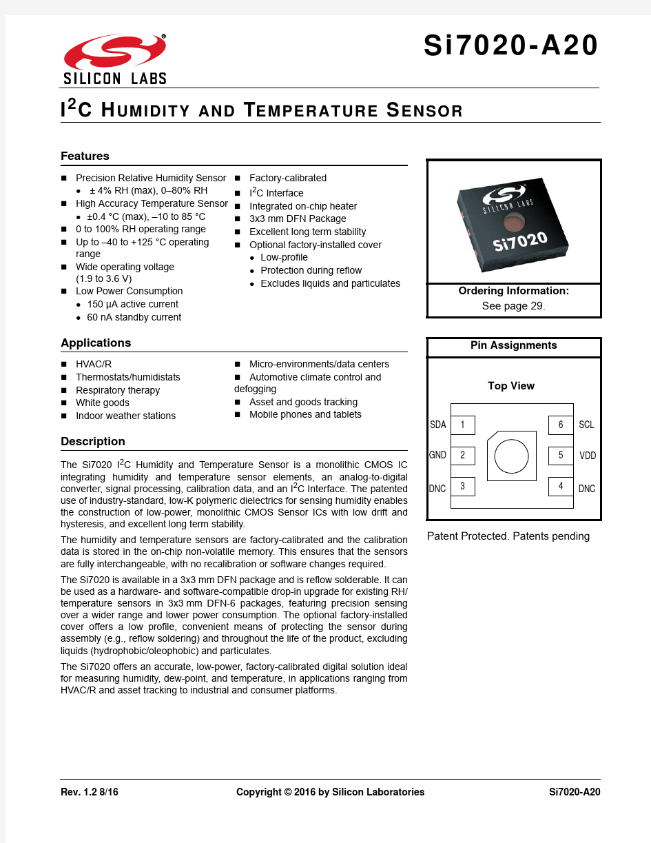
The Si7020 I 2C Humidity and Temperature Sensor is a monolithic CMOS IC integrating humidity and temperature sensor elements, an analog-to-digital converter, signal processing, calibration data, and an I 2C Interface. The patented use of industry-standard, low-K polymeric dielectrics for sensing humidity enables the construction of low-power, monolithic CMOS Sensor ICs with low drift and hysteresis, and excellent long term stability.
The humidity and temperature sensors are factory-calibrated and the calibration data is stored in the on-chip non-volatile memory. This ensures that the sensors are fully interchangeable, with no recalibration or software changes required.The Si7020 is available in a 3x3mm DFN package and is reflow solderable. It can be used as a hardware- and software-compatible drop-in upgrade for existing RH/temperature sensors in 3x3mm DFN-6 packages, featuring precision sensing over a wider range and lower power consumption. The optional factory-installed cover offers a low profile, convenient means of protecting the sensor during assembly (e.g., reflow soldering) and throughout the life of the product, excluding liquids (hydrophobic/oleophobic) and particulates.
The Si7020 offers an accurate, low-power, factory-calibrated digital solution ideal for measuring humidity, dew-point, and temperature, in applications ranging from HVAC/R and asset tracking to industrial and consumer platforms.
?Precision Relative Humidity Sensor ● ± 4% RH (max), 0–80% RH
?High Accuracy Temperature Sensor ● ±0.4°C (max), –10 to 85°C ?0 to 100% RH operating range ?Up to –40 to +125°C operating range
?Wide operating voltage (1.9 to 3.6V)
?
Low Power Consumption ● 150μA active current ● 60nA standby current
?Factory-calibrated
?I 2C Interface
?Integrated on-chip heater ?3x3mm DFN Package
?Excellent long term stability ?
Optional factory-installed cover ● Low-profile
● Protection during reflow
● Excludes liquids and particulates
?HVAC/R
?Thermostats/humidistats ?Respiratory therapy ?White goods
?
Indoor weather stations
?
Micro-environments/data centers ?Automotive climate control and defogging
?Asset and goods tracking ?Mobile phones and tablets
Patent Protected. Patents pending
Ordering Information:
See page
29.
Si7020-A20 Functional Block Diagram
Si7020-A20
Rev. 1.23
T ABLE OF C ONTENTS
Section
Page
1. Electrical Specifications . . . . . . . . . . . . . . . . . . . . . . . . . . . . . . . . . . . . . . . . . . . . . . . . . . .4
2. Typical Application Circuits . . . . . . . . . . . . . . . . . . . . . . . . . . . . . . . . . . . . . . . . . . . . . . .12
3. Bill of Materials . . . . . . . . . . . . . . . . . . . . . . . . . . . . . . . . . . . . . . . . . . . . . . . . . . . . . . . . . .13
4. Functional Description . . . . . . . . . . . . . . . . . . . . . . . . . . . . . . . . . . . . . . . . . . . . . . . . . . .14
4.1. Relative Humidity Sensor Accuracy . . . . . . . . . . . . . . . . . . . . . . . . . . . . . . . . . . . . .154.2. Hysteresis . . . . . . . . . . . . . . . . . . . . . . . . . . . . . . . . . . . . . . . . . . . . . . . . . . . . . . . . .164.3. Prolonged Exposure to High Humidity . . . . . . . . . . . . . . . . . . . . . . . . . . . . . . . . . . .164.4. PCB Assembly . . . . . . . . . . . . . . . . . . . . . . . . . . . . . . . . . . . . . . . . . . . . . . . . . . . . .164.
5. Protecting the Sensor . . . . . . . . . . . . . . . . . . . . . . . . . . . . . . . . . . . . . . . . . . . . . . . .184.
6. Bake/Hydrate Procedure . . . . . . . . . . . . . . . . . . . . . . . . . . . . . . . . . . . . . . . . . . . . . .184.
7. Long Term Drift/Aging . . . . . . . . . . . . . . . . . . . . . . . . . . . . . . . . . . . . . . . . . . . . . . . .185. I2C Interface . . . . . . . . . . . . . . . . . . . . . . . . . . . . . . . . . . . . . . . . . . . . . . . . . . . . . . . . . . . .19
5.1. Issuing a Measurement Command . . . . . . . . . . . . . . . . . . . . . . . . . . . . . . . . . . . . . .205.2. Reading and Writing User Registers . . . . . . . . . . . . . . . . . . . . . . . . . . . . . . . . . . . . .245.3. Electronic Serial Number . . . . . . . . . . . . . . . . . . . . . . . . . . . . . . . . . . . . . . . . . . . . .245.4. Firmware Revision . . . . . . . . . . . . . . . . . . . . . . . . . . . . . . . . . . . . . . . . . . . . . . . . . .255.5. Heater . . . . . . . . . . . . . . . . . . . . . . . . . . . . . . . . . . . . . . . . . . . . . . . . . . . . . . . . . . . .25
6. Control Registers . . . . . . . . . . . . . . . . . . . . . . . . . . . . . . . . . . . . . . . . . . . . . . . . . . . . . . . .26
6.1. Register Descriptions . . . . . . . . . . . . . . . . . . . . . . . . . . . . . . . . . . . . . . . . . . . . . . . .26
7. Pin Descriptions: Si7020 (Top View) . . . . . . . . . . . . . . . . . . . . . . . . . . . . . . . . . . . . . . . .28
8. Ordering Guide . . . . . . . . . . . . . . . . . . . . . . . . . . . . . . . . . . . . . . . . . . . . . . . . . . . . . . . . . .29
9. Package Outline . . . . . . . . . . . . . . . . . . . . . . . . . . . . . . . . . . . . . . . . . . . . . . . . . . . . . . . . .30
9.1. Package Outline: 3x3 6-pin DFN . . . . . . . . . . . . . . . . . . . . . . . . . . . . . . . . . . . . . . . .309.2. Package Outline: 3x3 6-pin DFN with Protective Cover . . . . . . . . . . . . . . . . . . . . . .3110. PCB Land Pattern and Solder Mask Design . . . . . . . . . . . . . . . . . . . . . . . . . . . . . . . . .3211. Top Marking . . . . . . . . . . . . . . . . . . . . . . . . . . . . . . . . . . . . . . . . . . . . . . . . . . . . . . . . . . .33
11.1. Si7020 Top Marking . . . . . . . . . . . . . . . . . . . . . . . . . . . . . . . . . . . . . . . . . . . . . . . .3311.2. Top Marking Explanation . . . . . . . . . . . . . . . . . . . . . . . . . . . . . . . . . . . . . . . . . . . .3312. Additional Reference Resources . . . . . . . . . . . . . . . . . . . . . . . . . . . . . . . . . . . . . . . . . .34Document Change List . . . . . . . . . . . . . . . . . . . . . . . . . . . . . . . . . . . . . . . . . . . . . . . . . . . . .35
Si7020-A20
1. Electrical Specifications
Unless otherwise specified, all min/max specifications apply over the recommended operating conditions.
Table 1. Recommended Operating Conditions
Parameter
Symbol Test Condition
Min Typ Max Unit Power Supply
V DD 1.9— 3.6V Operating Temperature T A I and Y grade –40—+125°C Operating Temperature
T A
G grade –40
—
+85
°C
Table 2. General Specifications
1.9 < V DD <3.6V; T A =–40 to 85°C (G grade) or –40 to 125°C (I/Y grade); default conversion time unless otherwise noted.
Parameter Symbol Test Condition Min Typ Max Unit Input Voltage High V IH SCL, SDA pins 0.7xV DD
——V Input Voltage Low V IL SCL, SDA pins
——0.3xV DD V Input Voltage Range V IN SCL, SDA pins with respect to GND
0.0—V DD V Input Leakage I IL SCL, SDA pins
——1μA Output Voltage Low
V OL
SDA pin; I OL =2.5mA;V DD =3.3V
——0.6V SDA pin; I OL =1.2mA;
V DD =1.9V
——0.4V Current
Consumption
I DD RH conversion in progress —150180μA Temperature conversion in progress
—90120μA Standby, –40 to +85°C 2—0.060.62μA Standby, –40 to +125°C 2—0.06 3.8μA Peak IDD during powerup 3— 3.5 4.0mA Peak IDD during I 2C operations 4
— 3.5 4.0mA Heater Current 5
I HEAT
—
3.1 to 9
4.2
—
mA
Notes:
1.Initiating a RH measurement will also automatically initiate a temperature measurement. The total conversion time will
be t CONV (RH) + t CONV (T).
2. No conversion or I 2C transaction in progress. Typical values measured at 25°C.
3. Occurs once during powerup. Duration is <5msec.
4. Occurs during I 2C commands for Reset, Read/Write User Registers, Read EID, and Read Firmware Version. Duration is
<100μs when I 2C clock speed is >100kHz (>200kHz for 2-byte commands).
5. Additional current consumption when HTRE bit enabled. See Section “5.5. Heater” for more information.
Si7020-A20
Conversion Time 1
t CONV
12-bit RH —1012ms
11-bit RH — 5.8710-bit RH — 3.7 4.58-bit RH — 2.6 3.114-bit temperature —710.813-bit temperature —4 6.212-bit temperature — 2.4 3.811-bit temperature
— 1.5 2.4Powerup Time
t PU
From V DD ≥1.9V to ready for a
conversion, 25°C —1825ms
From V DD ≥1.9V to ready for a conversion, full temperature range ——80After issuing a software reset
command
—
5
15
Table 2. General Specifications (Continued)
1.9 < V DD <3.6V; T A =–40 to 85°C (G grade) or –40 to 125°C (I/Y grade); default conversion time unless otherwise noted.
Parameter Symbol Test Condition Min Typ Max Unit
Notes:
1.Initiating a RH measurement will also automatically initiate a temperature measurement. The total conversion time will
be t CONV (RH) + t CONV (T).
2. No conversion or I 2C transaction in progress. Typical values measured at 25°C.
3. Occurs once during powerup. Duration is <5msec.
4. Occurs during I 2C commands for Reset, Read/Write User Registers, Read EID, and Read Firmware Version. Duration is
<100μs when I 2C clock speed is >100kHz (>200kHz for 2-byte commands).
5. Additional current consumption when HTRE bit enabled. See Section “5.5. Heater” for more information.
Si7020-A20
Figure 1.I
C Interface Timing Diagram
Table 3. I 2C Interface Specifications 1
1.9≤ V DD ≤ 3.6V; T A = –40 to +85°C (G grade) or –40 to +125°C (I/Y grade) unless otherwise noted.
Parameter
Symbol Test Condition Min Typ Max Unit Hysteresis V HYS High-to-low versus low-to-high transition
0.05 x V DD
——V SCLK Frequency 2f SCL ——400kHz SCL High Time t SKH 0.6——μs SCL Low Time t SKL 1.3——μs Start Hold Time t STH 0.6——μs Start Setup Time t STS 0.6——μs Stop Setup Time t SPS 0.6
——μs Bus Free Time t BUF Between Stop and Start 1.3——μs SDA Setup Time t DS 100——ns SDA Hold Time t DH 100
——ns SDA Valid Time
t VD;DAT From SCL low to data valid ——0.9μs SDA Acknowledge Valid Time t VD;ACK From SCL low to data valid
——0.9μs Suppressed Pulse Width 3
t SPS
50
—
—
ns
Notes:
1.All values are referenced to V IL and/or V IH .
2. Depending on the conversion command, the Si7020 may hold the master during the conversion (clock stretch). At
above 100kHz SCL, the Si7020 may also hold the master briefly for user register and device ID transactions. At the highest I 2C speed of 400kHz the stretching will be <50μs.3. Pulses up to and including 50ns will be suppressed.
Si7020-A20
Table 4. Humidity Sensor
1.9 ≤ V DD ≤ 3.6V; T A = 30°C; default conversion time unless otherwise noted.
Parameter Symbol Test Condition Min Typ Max Unit
Operating Range 1Non-condensing 0—100%RH Accuracy 2, 30 – 80% RH —±3±4%RH
80 – 100% RH See Figure 2.
Repeatability/Noise
12-bit resolution —0.025—%RH RMS
11-bit resolution —0.05—10-bit resolution —0.1—8-bit resolution —0.2—Response Time 4τ63%
1m/s airflow, with cover —18—S 1m/s airflow, without cover
—17—Drift vs. Temperature —0.05—%RH/°C Hysteresis
—±1—%RH Long Term Stability 3
—
<0.25
—
%RH/yr
Notes:
1.Recommended humidity operating range is 20% to 80% RH (non-condensing) over –10°C to 60°C. Prolonged
operation beyond these ranges may result in a shift of sensor reading, with slow recovery time.
2. Excludes hysteresis, long term drift, and certain other factors and is applicable to non-condensing environments only.
See Section “4.1. Relative Humidity Sensor Accuracy” for more details.
3. Drift due to aging effects at typical room conditions of 30°C and 30% to 50% RH. May be impacted by dust, vaporized
solvents or other contaminants, e.g., out-gassing tapes, adhesives, packaging materials, etc. See Section “4.7. Long Term Drift/Aging” .
4. Response time to a step change in RH. Time for the RH output to change by 63% of the total RH change.
Si7020-A20
Figure2.RH Accuracy at 30°C
Si7020-A20
Table 5. Temperature Sensor
1.9≤ V DD ≤3.6V; T A =–40 to +85°C (G grade) or –40 to +125°C (I/Y grade) default conversion time, unless otherwise noted.
Parameter Symbol Test Condition Min Typ Max Unit
Operating Range I and Y Grade –40—+125°C G Grade
–40—+85°C Accuracy 1
–10°C ±0.3±0.4 °C –40 Figure 3. Repeatability/Noise 14-bit resolution —0.01—°C RMS 13-bit resolution —0.02—12-bit resolution —0.04—11-bit resolution —0.08—Response Time 2 τ63% Unmounted device —0.7—s Si7020-EB board — 5.1 —s Long Term Stability — 0.01 — °C/Yr Notes: 1.14b measurement resolution (default). 2. Time to reach 63% of final value in response to a step change in temperature. Actual response time will vary dependent on system thermal mass and air-flow. Si7020-A20 Figure 3. Temperature Accuracy* *Note: Applies only to I and Y grade devices beyond +85°C. Si7020-A20 Table 6. Thermal Characteristics Parameter Symbol Test Condition DFN-6Unit 256°C/W Junction to Air Thermal ResistanceθJA JEDEC 2-Layer board, No Airflow 224°C/W Junction to Air Thermal ResistanceθJA JEDEC 2-Layer board, 1 m/s Airflow Junction to Air Thermal ResistanceθJA JEDEC 2-Layer board, 205°C/W 2.5 m/s Airflow Junction to Case Thermal ResistanceθJC JEDEC 2-Layer board22°C/W Junction to Board Thermal ResistanceθJB JEDEC 2-Layer board134°C/W Table 7. Absolute Maximum Ratings1 Parameter Symbol Test Condition Min Typ Max Unit Ambient temperature –55—125°C under bias Storage Temperature2–65—150°C Voltage on I/O pins –0.3—V DD+0.3V V –0.3— 4.2V Voltage on VDD with respect to GND ESD Tolerance HBM——2kV CDM—— 1.25kV MM——250V Notes: 1.Absolute maximum ratings are stress ratings only, operation at or beyond these conditions is not implied and may shorten the life of the device or alter its performance. 2. Special handling considerations apply; see application note, “AN607: Si70xx Humidity Sensor Designer’s Guide”. Si7020-A20 2. Typical Application Circuits The primary function of the Si7020 is to measure relative humidity and temperature. Figure4 demonstrates the typical application circuit to achieve these functions. Figure4. Si7020-A20 3. Bill of Materials Table 8. Typical Application Circuit BOM for Relative Humidity and Temperature Measurement Reference Description Mfr Part Number Manufacturer R1Resistor, 10kΩ, ±5%, 1/16W, 0603CR0603-16W-103JT Venkel R2Resistor, 10kΩ, ±5%, 1/16W, 0603CR0603-16W-103JT Venkel C1Capacitor, 0.1μF, 16V, X7R, 0603C0603X7R160-104M Venkel U1IC, Digital Temperature/humidity Sensor Si7020-A20-GM Silicon Labs Si7020-A20 4. Functional Description Figure 5.Si7020 Block Diagram The Si7020 is a digital relative humidity and temperature sensor that integrates temperature and humidity sensor elements, an analog-to-digital converter, signal processing, calibration, polynomial non-linearity correction, and an I 2C interface all in a single chip. The Si7020 is individually factory-calibrated for both temperature and humidity,with the calibration data stored in on-chip non-volatile memory. This ensures that the sensor is fully interchangeable, with no recalibration or changes to software required. Patented use of industry-standard CMOS and low-K dielectrics as a sensor enables the Si7020 to achieve excellent long term stability and immunity to contaminants with low drift and hysteresis. The Si7020 offers a low-power, high-accuracy, calibrated and stable solution ideal for a wide range of temperature, humidity, and dew-point applications including medical and instrumentation, high-reliability automotive and industrial systems, and cost-sensitive consumer electronics.While the Si7020 is largely a conventional mixed-signal CMOS integrated circuit, relative humidity sensors in general and those based on capacitive sensing using polymeric dielectrics have unique application and use requirements that are not common to conventional (non-sensor) ICs. Chief among those are: ? The need to protect the sensor during board assembly, i.e., solder reflow, and the need to subsequently rehydrate the sensor. ? The need to protect the senor from damage or contamination during the product life-cycle. ? The impact of prolonged exposure to extremes of temperature and/or humidity and their potential effect on sensor accuracy. ? The effects of humidity sensor “memory”. Each of these items is discussed in more detail in the following sections. Si7020-A20 4.1. Relative Humidity Sensor Accuracy To determine the accuracy of a relative humidity sensor, it is placed in a temperature and humidity controlled chamber. The temperature is set to a convenient fixed value (typically 25–30°C) and the relative humidity is swept from 20 to 80% and back to 20% in the following steps: 20% – 40% – 60% – 80% – 80% – 60% – 40% – 20%. At each set-point, the chamber is allowed to settle for a period of 60 minutes before a reading is taken from the sensor. Prior to the sweep, the device is allowed to stabilize to 50%RH. The solid trace in Figure 6, “Measuring Sensor Accuracy Including Hysteresis,” shows the result of a typical sweep. Figure 6. Measuring Sensor Accuracy Including Hysteresis The RH accuracy is defined as the dotted line shown in Figure 6, which is the average of the two data points at each relative humidity set-point. In this case, the sensor shows an accuracy of 0.25%RH. The Si7020 accuracy specification (Table 4) includes: ? Unit-to-unit and lot-to-lot variation ? Accuracy of factory calibration ? Margin for shifts that can occur during solder reflow The accuracy specification does not include: ? Hysteresis (typically ±1%) ? Effects from long term exposure to very humid conditions ? Contamination of the sensor by particulates, chemicals, etc.? Other aging related shifts ("Long-term stability") ? Variations due to temperature (see Drift vs. Temperature in Table 4). RH readings will typically vary with temperature by less than ± 0.05% ? C . Si7020-A20 4.2. Hysteresis The moisture absorbent film (polymeric dielectric) of the humidity sensor will carry a memory of its exposure history, particularly its recent or extreme exposure history. A sensor exposed to relatively low humidity will carry a negative offset relative to the factory calibration, and a sensor exposed to relatively high humidity will carry a positive offset relative to the factory calibration. This factor causes a hysteresis effect illustrated by the solid trace in Figure 6. The hysteresis value is the difference in %RH between the maximum absolute error on the decreasing humidity ramp and the maximum absolute error on the increasing humidity ramp at a single relative humidity setpoint and is expressed as a bipolar quantity relative to the average error (dashed trace). In the example of Figure 6, the measurement uncertainty due to the hysteresis effect is ±1.0%RH. 4.3. Prolonged Exposure to High Humidity Prolonged exposure to high humidity will result in a gradual upward drift of the RH reading. The shift in sensor reading resulting from this drift will generally disappear slowly under normal ambient conditions. The amount of shift is proportional to the magnitude of relative humidity and the length of exposure. In the case of lengthy exposure to high humidity, some of the resulting shift may persist indefinitely under typical conditions. It is generally possible to substantially reverse this affect by baking the device (see Section “4.6. Bake/Hydrate Procedure” ). 4.4. PCB Assembly 4.4.1. Soldering Like most ICs, Si7020 devices are shipped from the factory vacuum-packed with an enclosed desiccant to avoid any RH accuracy drift during storage and to prevent any moisture-related issues during solder reflow. The following guidelines should be observed during PCB assembly: ? Si7020 devices are compatible with standard board assembly processes. Devices should be soldered using reflow per the recommended card reflow profile. See Section “10. PCB Land Pattern and Solder Mask Design” for the recommended card reflow profile. ? A "no clean" solder process is recommended to minimize the need for water or solvent rinses after soldering. Cleaning after soldering is possible, but must be done carefully to avoid impacting the performance of the sensor. See “AN607: Si70xx Humidity Sensor Designer’s Guide” for more information on cleaning. ? It is essential that the exposed polymer sensing film be kept clean and undamaged. This can be accomplished by careful handling and a clean, well-controlled assembly process. When in doubt or for extra protection, a heat-resistant, protective cover such as Kapton? KPPD-1/8 polyimide tape can be installed during PCB assembly. Si7020s may be ordered with a factory-fitted, solder-resistant protective cover. This cover provides protection during PCB assembly or rework but without the time and effort required to install and remove the Kapton tape. It can be left in place for the lifetime of the product, preventing liquids, dust or other contaminants from coming into contact with the polymer sensor film. See Section “8. Ordering Guide” for a list of ordering part numbers that include the cover.4.4.2. Rehydration The measured humidity value will generally shift slightly after solder reflow. A portion of this shift is permanent and is accounted for in the accuracy specifications in Table 4. After soldering, an Si7020 should be allowed to equilibrate under controlled RH conditions (room temperature, 45–55%RH) for at least 48 hours to eliminate the remainder of the shift and return the device to its specified accuracy performance. Si7020-A20 4.4.3. Rework To maintain the specified sensor performance, care must be taken during rework to minimize the exposure of the device to excessive heat and to avoid damage/contamination or a shift in the sensor reading due to liquids, solder flux, etc. Manual touch-up using a soldering iron is permissible under the following guidelines: ? The exposed polymer sensing film must be kept clean and undamaged. A protective cover is recommended during any rework operation (Kapton? tape or the factory installed cover). ? Flux must not be allowed to contaminate the sensor; liquid flux is not recommended even with a cover in place. Conventional lead-free solder with rosin core is acceptable for touch-up as long as a cover is in place during the rework. ? If possible, avoid water or solvent rinses after touch-up. Cleaning after soldering is possible, but must be done carefully to avoid impacting the performance of the sensor. See “AN607: Si70xx Humidity Sensor Designer’s Guide” for more information on cleaning. ? Minimize the heating of the device. Soldering iron temperatures should not exceed 350 °C and the contact time per pin should not exceed five seconds. ? Hot air rework is not recommended. If a device must be replaced, remove the device by hot air and solder a new part in its place by reflow following the guidelines above. *Note:All trademarks are the property of their respective owners. Figure7. Si7020 with Factory-Installed Protective Cover Si7020-A20 4.5. Protecting the Sensor Because the sensor operates on the principal of measuring a change in capacitance, any changes to the dielectric constant of the polymer film will be detected as a change in relative humidity. Therefore, it is important to minimize the probability of contaminants coming into contact with the sensor. Dust and other particles as well as liquids can affect the RH reading. It is recommended that a cover is employed in the end system that blocks contaminants but allows water vapor to pass through. Depending on the needs of the application, this can be as simple as plastic or metallic gauze for basic protection against particulates or something more sophisticated such as a hydrophobic membrane providing up to IP67 compliant protection. The Si7020 may be ordered with a factory-fitted, solder-resistant cover that can be left in place for the lifetime of the product. It is very low-profile, hydrophobic and oleophobic. See Section “8. Ordering Guide” for a list of ordering part numbers that include the cover. A dimensioned drawing of the IC with the cover is included in Section “9. Package Outline” . Other characteristics of the cover are listed in Table9. Table 9. Specifications of Protective Cover Parameter Value Material PTFE Operating Temperature–40 to 125°C Maximum Reflow Temperature260°C IP Rating (per IEC 529)IP67 4.6. Bake/Hydrate Procedure After exposure to extremes of temperature and/or humidity for prolonged periods, the polymer sensor film can become either very dry or very wet, in each case the result is either high or low relative humidity readings. Under normal operating conditions, the induced error will diminish over time. From a very dry condition, such as after shipment and soldering, the error will diminish over a few days at typical controlled ambient conditions, e.g., 48hours of 45≤%RH≤55. However, from a very wet condition, recovery may take significantly longer. To accelerate recovery from a wet condition, a bake and hydrate cycle can be implemented. This operation consists of the following steps: ? Baking the sensor at 125°C for ≥ 12 hours ? Hydration at 30°C in 75% RH for ≥ 10 hours Following this cycle, the sensor will return to normal operation in typical ambient conditions after a few days. 4.7. Long Term Drift/Aging Over long periods of time, the sensor readings may drift due to aging of the device. Standard accelerated life testing of the Si7020 has resulted in the specifications for long-term drift shown in Table4 and Table5. This contribution to the overall sensor accuracy accounts only for the long-term aging of the device in an otherwise benign operating environment and does not include the effects of damage, contamination, or exposure to extreme environmental conditions. Si7020-A20 5. I2C Interface The Si7020 communicates with the host controller over a digital I2C interface. The 7-bit base slave address is 0x40. Table 10. I2C Slave Address Byte A6A5A4A3A2A1A0R/W 10000000 Master I2C devices communicate with the Si7020 using a command structure. The commands are listed in the I2C command table. Commands other than those documented below are undefined and should not be sent to the device. Table 11. I2C Command Table Command Description Command Code Measure Relative Humidity, Hold Master Mode0xE5 Measure Relative Humidity, No Hold Master Mode0xF5 Measure Temperature, Hold Master Mode0xE3 Measure Temperature, No Hold Master Mode0xF3 Read Temperature Value from Previous RH Measurement0xE0 Reset0xFE Write RH/T User Register 10xE6 Read RH/T User Register 10xE7 Write Heater Control Register0x51 Read Heater Control Register0x11 Read Electronic ID 1st Byte0xFA 0x0F Read Electronic ID 2nd Byte0xFC 0xC9 Read Firmware Revision0x84 0xB8 Si7020-A20 5.1. Issuing a Measurement Command The measurement commands instruct the Si7020 to perform one of two possible measurements; Relative Humidity or Temperature. The procedure to issue any one of these commands is identical. While the measurement is in progress, the option of either clock stretching (Hold Master Mode) or Not Acknowledging read requests (No Hold Master Mode) is available to indicate to the master that the measurement is in progress; the chosen command code determines which mode is used. Optionally, a checksum byte can be returned from the slave for use in checking for transmission errors. The checksum byte will follow the least significant measurement byte if it is acknowledged by the master. The checksum byte is not returned if the master “not acknowledges” the least significant measurement byte. The checksum byte is calculated using a CRC generator polynomial of x8 + x5 + x4 + 1, with an initialization of 0x00. The checksum byte is optional after initiating an RH or temperature measurement with commands 0xE5, 0xF5, 0xE3, and 0xF3. The checksum byte is required for reading the electronic ID with commands 0xFA 0x0F and 0xFC 0xC9. For all other commands, the checksum byte is not supported. Table 12. I2C Bit Descriptions Name Symbol Description START S SDA goes low while SCL high. STOP P SDA goes high while SCL high. Repeated START Sr SDA goes low while SCL high. It is allowable to generate a STOP before the repeated start. SDA can transition to high before or after SCL goes high in preparation for generating the START. READ R Read bit=1 WRITE W Write bit=0 All other bits—SDA value must remain high or low during the entire time SCL is high (this is the set up and hold time in Figure1). In the I2C sequence diagrams in the following sections, bits produced by the master and slave are color coded as shown: Master Slave 国家开放大学教师教育网 学员使用说明书 自强求知有为 目录 一、登录到学员工作室 1、在网页地址栏输入“”),进入国家开放大学教师教育培训网首页,(建议收藏本网址,以便后续可以快速进入培训界面,同时按住crl+D可收藏网址) 2、点击下图中红框标注部分,在打开的界面中输入账号、密码进入培训平台。 温馨提示: (1)用户名请使用下发的账号,初次登录时密码使用下发的初始密码 (2)如果忘记密码,可以联系中央电大 3.登录之后进入到了选课页面,因为本项目课程全部为必修,点击页面下方的“保存选课”按钮即可,如下图: 4.选课成功之后就进入到了个人信息确认页面,按照页面提示一步一步填写个人信息即可。 二、学员工作室首页简介 学员成功登录到学习工作室后的页面如下图所示,主要分为了7各部分,如下图中红框所示,此外右下角还有本省学员登录平台时间的排行榜。以下将分别介绍各个版块的功能及操作。 三、功能介绍及操作说明 (一)页面顶端导航栏 1 2 3 4 5 6 1、工作室首页:学员在个人工作室浏览到任何界面时,点击“工作室首页” 均可返回到工作室首页。 2、我的社区:可从下拉菜单中分别选择广场、区域、学校及其他工作坊进 入查看资源和活动。 3、资源中心:可进入查看国家开放大学教师教育网所有的生成性资源,与 所有参训老师分享培训所获。 4、 消息: 通过这个小功能可以给别人发站内信,查看、回复其他人给自己发的站内信、也可以查询自己给别人发信的记录。发站内信的操作如下图所示: 5、 设置:点击设置,学员可修改、完善个人信息,修改密码,详见下图。 6、 退出:点击退出按钮,退出登录状态,返回到“国家开放大学教师教育网”首页。 (二)查看功能 了解该项目的学习要求,考核方案、学习进度、班级简报、课程简报、学 查收、回复收到的站内信 查看已发的站内信 给别人发站 内信 修改、完善个人 修改 公共数据开放平台 产品白皮书 第一章行业背景 随着各行各业飞速迅猛的发展,信息资源也在日新月异的增长,信息掌握的多寡成为各国软实力和竞争力的重要标志。2011年以来,美国、英国等国家在全球掀起了政府开放数据热潮,至今全球已有超过65个国家已加入公共信息资源开放的行列中,普遍建立了依托互联网面向社会提供开放数据的统一网站。我国各省市也纷纷开始实施数据开放工作,继北京、上海之后,浙江、青岛等省市也纷纷开通了数据网站。 虽然国内各地的数据网站都在逐步建立,但都是各自为营、相对独立,缺少统一的标准、统一的格式、统一的目录等,使得国内没有一个统一的数据开放网站,对外缺少统一的面向世界的中国数据开放网站。 因此,我们设计实现的公共数据开放平台,在国家级、省级“两级建设”,在国家、省、市、县、乡镇“五级使用”,基于互联网,构成集中的、专用的信息资源开放共享平台。 第二章产品概述 公共数据开放平台,能够为各级政府职能部门、企事业单位提供关于政府部门业务信息、公共事业服务信息等资源的发布、展示、下载、查询和交流等功能。本产品是基于互联网的、专用的、集中的网站,是公共信息资源开放共享的载体。信息资源形式包括结构化数据和非结构化数据,基于云计算技术,充分利用现有的电子政务公共平台,采用自主可控的软硬件设备进行构建,满足快速部署、安全可靠、易于扩展和多并发访问。 本产品作为管理机构、开放机构、社会公众的共用平台,能够起到四方面作用: 1、渠道作用:通过数据网站开放公共信息资源;社会公众通过数据网站获取公共信息资源;管理机构通过数据网站对公共信息资源开放共享过程进行管理、对成效进行评估考核。 2、桥梁作用:通过数据网站建立起开放机构和社会公众交流互动的桥梁,社会公众可通过数据网站向开放机构提出数据开放需求,评价已开放数据的质量;开放机构则可以通过数据网站响应社会公众需求,不断扩大开放范围,提高数据质量。 3、窗口作用:数据网站是公共信息资源开放的宣传和监督窗口,公布公共信息资源开放共享相关要求、开放计划、开放机构的考核排名,接受社会各界监督;公布鼓励公共信息资源开放共享和再利用的政策、发布优秀信息服务产品,促进信息服务产业链形成。 4、支撑作用:数据网站要为公共信息资源开放全过程提供基础设施资源、网络资源、计算资源、存储资源等信息化基础支撑;为公共信息资源的开放、存储和再利用提供数据采集工具、管理工具、分析处理工具等技术支撑。 第三章产品定位 1、解决的问题:本产品主要是满足各级政府部门、公共企事业单位开放各自的数据,能够集中统一建设可以避免重复投资和资源浪费,可以实现数据再处理以及信息产品的生产和提供,可使社会公众方便、低成本的使用和获取开放数据。 2、服务的客户群:本产品通过互联网面向社会公众,大体分两类用户:开放机构和使用数据用户。开放机构通过网站进行上传、管理各自的数据,使用者包括个人、企业机构、科研院所等,可以下载数据直接利用,或再次加工成数据产品、APP应用等。 3、与竞品的差异:本产品与其他省、市的数据开放网站不同在于,能够建设统一的实体数据网站,采用唯一的顶级域名,社会公众可从统一的入口进入,对全省的数据进行检索。所属地市可在省级实体网站上创建各自的虚拟网站,拥有二级域名,并不实际占用存储空间。能够降低建设成本、缩短建设周期。另外, h u t. e d u.c n 1.如何阅读本章 所有LPC111x系列中的SPI模块均相同。第二个SPI模块,SPI1,只存在于 LQFP48和PLCC44封装上,在HVQFN33封装上则没有。 注释:两个SPI模块都包含全部的SSP特征集,所有相关寄存器都使用 SSP前缀命名。 2.特性 ?兼容Motorola SPI、4线TI SSI和美国国家半导体公司的Microwire总线。 ?同步串行通信。 ?支持主机和从机操作。 ?收发均有8帧FIFO。 ?每帧有4-16位数据。 3.基本描述 SPI/SSP是一个同步串行端口(SSP)控制器,可控制SPI、4线SSI和Microwire总线。它 可以与总线上的多个主机和从机相互作用。在数据传输过程中,总线上只能有一个主机与 一个从机进行通信。原则上数据传输是全双工的,4~16位帧的数据由主机发送到从机或 由从机发送到主机。但实际上,大多数情况下只有一个方向上的数据流包含有意义的数 据。 LPC111x系列处理器有两个SPI/同步串行端口控制器。 u p .w u p .w h u t.e d u .c n 4.引脚描述 表16 1622.SPI引脚描述 SCK0/1I/O SCK CLK SK串行时钟。SCK/CLK/SK是用来同步数据传输的时 钟信号。它由主机驱动,从机接收。当使用SPI接口 时,时钟可编程为高电平有效或低电平有效,否则 总是高电平有效。SCK仅在数据传输过程中切换。 在其它时间里,SPI/SSP接口保持无效状态或不驱 动它(使其处于高阻态)。 SSEL0/1I/O SSEL FS CS帧同步/从机选择。当SPI/SSP接口是总线主机 时,它在串行数据启动前驱动该信号为有效状态。 在数据发送出去之后又将该信号恢复为无效状态。 该信号的有效状态根据所选的总线和模式可以是高 或低。当SPI/SSP接口作为总线从机时,该信号根 据使用的协议来判断主机数据的存在。 当只有一个总线主机和一个总线从机时,来至主机 的帧同步信号或从机选择信号直接与从机相应的输 入相连。当总线上接有多个从机时,需要管理好这 些从机的帧选择/从机选择输入,以免一次传输有多 个从机响应。 MISO0/1I/O MISO DR(M) DX(S) MOSI0/1I/O MOSI DX(M) DR(S)SI(M) SO(S) SO(M) SI(S) 主机输入从机输出。MISO信号线从从机传送串行数 据传送到主机。当SPI/SSP作为从机,串行数据从 该信号输出。当SPI/SSP作为主机,从该信号得到 串行数据时钟。当SPI/SSP作为从机但未被 FS/SSEL选定,它不会驱动该信号(保持高阻态)。 主机输出从机输入。MOSI信号线从主机传送串行 数据到从机。当SPI/SSP作为主机,串行数据从 该信号输出。当SPI/SSP作为从机,从该信号得 到串行数据时钟。 注释:SCK0功能在三个不同的引脚上复用(在HVQFN封装上有两个引脚)。通过设置IOCON_LOC寄存器(见7–4.2小节)选择一个引脚作为SCK0功能,另外在IOCON寄存器中设置功能。SCK1引脚没有复用。 京东商城数据开放平台使用手册 系统简介 京东数据开放平台是京东最新推出的、为POP商家提供运营管理及决策支持的数据平台。它通过对店铺的客户访问题及经营状况等数据进行分析、解读,帮助掌柜更好的了解店铺的经营情况,为店铺经营决策提供充分的数据支持。 术语说明 最近上架时间:商品最近一次设置为可售状态的时间。 SPU:是商品信息聚合的最小单位,是一组可复用、易检索的标准化信息的集合,该集合描述了一个产品的特性。通俗点讲,属性值、特性相同的商品就可以称为一个SPU。SKU:即库存进出计量的单位,可以是以件、盒、托盘等为单位。在服装、鞋类商品中使用最多最普遍。例如纺织品中一个SKU通常表示:规格、颜色、款式。 合并SKU:合并SKU,统计到SPU粒度;不选择合并SKU,数据统计到SKU粒度。 指标说明 数据开放平台涉及到的统计指标主要有:上架商品数量、下单量、下单商品件数、下单金额、下单客户数、平均订单金额、客单价、客户转化率、下单转化率、商品关注量、客单量、下单商品SKU数量、浏览量(PV)、访问次数、访客数(UV)。 上架商品数量:统计期截止时间点的上架的商品数量。 下单量:统计期内客户提交的总订单量(先款订单付款后列入统计,先货订单提交后列入统计) 下单商品件数:统计期内提交的订单包含的总商品件数(先款订单付款后列入统计,先货订单提交后列入统计) 下单金额:统计期内提交的订单金额之和(先款订单付款后列入统计,先货订单提交后列入统计) 下单客户数:统计期内提交订单的客户数(先款订单付款后列入统计,先货订单提交后列入统计) 平均订单金额:平均订单金额=下单金额/订单量。 客单价:客单价=下单金额/下单客户数。 客户转化率:客户转化率=下单客户数/访客数。 下单转化率:下单转化率=下单量/访问次数。 商品关注量:统计期截止时间点对商品添加关注的客户数。 供应商协同平台商品管理操作说明书 目录 1引言........................................................... 错误!未定义书签。 系统用途..................................................... 错误!未定义书签。 编写目的..................................................... 错误!未定义书签。 参考资料..................................................... 错误!未定义书签。 术语和缩写词................................................. 错误!未定义书签。2系统概述....................................................... 错误!未定义书签。 状态图....................................................... 错误!未定义书签。 用户描述。................................................... 错误!未定义书签。 3.系统使用过程................................................... 错误!未定义书签。 系统访问地址................................................. 错误!未定义书签。 新品提报..................................................... 错误!未定义书签。 流程说明................................................. 错误!未定义书签。 操作说明................................................. 错误!未定义书签。 录入基本信息规则说明................................. 错误!未定义书签。 录入规格参数......................................... 错误!未定义书签。 录入扩展属性......................................... 错误!未定义书签。 录入商品介绍......................................... 错误!未定义书签。 录入视频介绍........................................ 错误!未定义书签。 提交审核............................................. 错误!未定义书签。 预览................................................. 错误!未定义书签。 克隆................................................. 错误!未定义书签。 老品维护..................................................... 错误!未定义书签。 流程说明................................................. 错误!未定义书签。 操作说明................................................. 错误!未定义书签。 菜单位置............................................. 错误!未定义书签。 修改基本信息规则说明................................. 错误!未定义书签。 修改规格参数......................................... 错误!未定义书签。 APC330/Si4438小功率无线数传模块DVER1.0 APC330模块是高度集成低功耗半双工小功率无线数据传输模块,其嵌入高速低功耗单片机和高性能射频芯片SI4438,创新的采用高效的循环交织纠检错编码,抗干扰和灵敏度都大大提高,APC330模块提供了多个频道的选择,可在线修改串口速率,收发频率,发射功率,射频速率等各种参数。 APC330模块工作电压为3.5-5.5V,在接收状态下仅消耗16mA。APC330模块能够透明传输任何大小的数据,而用户无须编写复杂的设置与传输程序, 应用: ●无线电能表 ●无线传感器 ●集装箱信息管理 ●自动化数据采集 ●工业遥控,遥测 ●POS系统,资产管理 ●楼宇小区自动化与安防 ● 机器人控制同时小体积宽电较远传输距离,使之能够应用与非常广泛的领域。 特点: ●1500米传输距离(1Kbps) ●频率425-450MHz,或470-510MHz ●-120dBm@1Kbps高灵敏度 ●最大发射功率100mW(可设置) ●多频道可设,双256Bytes数据缓冲区●高效的循环交织纠错编码 ●内置watchdog APC330模块是新一代的多通道嵌入式无线数传模块,可设置多个频道,步进为1KHz,发射功率最大100mW,体积32.1mm x18.3mm x7.0mm,很方便客户嵌入系统之内,APC330模块具有较低的功耗,非常适合于电池供电系统。 APC330模块创新的采用了高效的循环交织纠检错编码,其编码增益高达近3dBm,纠错能力和编码效率均达到业内的领先水平,远远高与一般的前向纠错编码,抗突发干扰和灵敏度都较大的改善。同时编码也包含可靠检错能力,能够自动滤除错误及虚假信息,真正实现了透明的连接。所以APC330模块特别适合于在工业领域等强干扰的恶劣环境中使用。 APC330模块内设双256Bytes大容量缓冲区,在缓冲区为空的状态下,用户可以1次传输256Bytes的数据,当设置空中波特率大于串口波特率时,可1次传输无限长度的数据,同时APC330模块提供标准的UART/TTL接口,1200/2400/4800/9600/19200/38400/57600bps七种速率,和三种接口校验方式。APC330模块外部接口采用透明数据传输传输方式,能适应标准或非标准的用户协议,所收的数据就是所发的数据。 设置模块采用串口设置模块参数,具有丰富便捷的软件编程设置选项,包括频点,空中速率,以及串口速率,校验方式,等都可设置,设置方式有二种方式,一是通过配套提供的设置软件RF-Magic利用PC串口即可,二是动态在线设置,用串口发命令动态修改,具体方法参见APC330模块的参数设置章节。 引脚定义: APC330模块共有9个接脚,具体定义如下表: APC330引脚定义 引脚定义方向说明 1GND-地0V 2VCC- 2.1V-3.6V,可定制3.5-5.5V 3EN输入(有极弱上拉)使能脚,高电平有效,上拉电阻为1M 4RXD输入(有弱上拉)UART输入口,TTL电平,上拉电阻约47K 5TXD输出UART输出口,TTL电平,可定制OC输出 新点大数据平台软件 操作手册 一、第一章、平台建设背景 当今世界,信息技术与经济社会的交会融合引发数据迅猛增长,数据已成为国家基础性战略资源。大数据的发展和应用正日益对全球生产、流通、分配、消费活动以及经济运行机制、社会生活方式和政府治理能力产生重要影响。 2014年,“大数据”被首次写入政府工作报告以来,中央主要领导对大数据中心的建设及大数据技术的应用高度重视,国务院及有关部门也陆续发布了一系列的文件。2015年,《关于运用大数据加强对市场主体服务和监管的若干意见》、《关于积极推进“互联网+”行动的指导意见》和《促进大数据发展行动纲要》陆续颁布,2016年,《政务信息资源共享管理暂行办法》,明确规范政务部门间政务信息资源共享工作,2017年,《政务信息系统整合共享实施方案》,建立全国政务信息资源目录体系,政务信息系统整合共享取得显著成效,重要政务信息系统实现互联互通。这几份重磅文件密集出台,标志着我国政府大数据战略部署和顶层设计正式确立,大数据的开发应用必将使政府治理“如虎添翼”。 二、第二章、建设原则 建设大数据平台可以划分为四个阶段:信息资源规划、数据共享、数据开放、融合应用。 2.1、信息资源规划 信息资源规划是政府管理、资源共享、电子政务建设的基础。信息资源规划是以摸清政府部门信息资源底数为基础,以较为明确的需求如人口、法人、电子证照、地理信息为导向,通过信息资源规划IRP理论体系,按照三定方案或职责清单对政府业务进行分析,划分职能、梳理职能事项,并识别事项运行所发生的信息资源,详细描述信息资源的基础属性、采集属性、共享属性、开放属性等各类属性。 2.2、数据共享 政务大数据平台建设第二阶段的主要任务就是先把政府部门之间的数据共享做起来,以数据应用为导向,综合考虑管理难度和技术难度,通过统一规划, Vishay Siliconix Si3993DV Dual P-Channel 30-V (D-S) MOSFET FEATURES ?Halogen-free According to IEC 61249-2-21 Definition ?TrenchFET ? Power MOSFET ?Symetrical Dual P-Channel ?Compliant to RoHS Directive 2002/95/EC APPLICATIONS ?Battery Switch for Portable Devices ?Computers - Bus Switch - Load Switch PRODUCT SUMMARY V DS (V)R DS(on) (Ω)I D (A)- 30 0.133 at V GS = - 10 V - 2.20.245 at V GS = - 4.5 V - 1.6 Notes: a. Surface Mounted on 1" x 1" FR4 board. ABSOLUTE MAXIMUM RATINGS T A = 25 °C, unless otherwise noted Parameter Symbol 5 s Steady State Unit Drain-Source Voltage V DS - 30V Gate-Source Voltage V GS ± 20 Continuous Drain Current (T J = 150 °C)a T A = 25 °C I D - 2.2- 1.8A T A = 70 °C - 1.7 - 1.4 Pulsed Drain Current I DM - 8 Continuous Source Current (Diode Conduction)a I S - 1.05- 0.75Maximum Power Dissipation a T A = 25 °C P D 1.150.83W T A = 70 °C 0.73 0.53 Operating Junction and Storage T emperature Range T J , T stg - 55 to 150°C THERMAL RESISTANCE RATINGS Parameter Symbol Typical Maximum U nit Maximum Junction-to-Ambient a t ≤ 5 s R thJA 93110°C/W Steady State 130150Maximum Junction-to-Foot (Drain)Steady State R thJF 75 90 信息服务平台使用说明 技术部开发的信息服务平台的目的在于为我院广大学生和合作助学站点提供信息查询及相关业务操作的服务,使他们能够直接通过互联网能够查询到自身相关信息,提高我院办学服务水平。 目前已开放学生的查询功能和学位课程申报功能,站点的功能正在开发中。 1.使用流程 首先通过我院网站首页进入信息服务平台的首页(图1),该平台用户主要有三类:院内用户,学生用户及站点用户。院内用户指我院内部相关的业务人员,而学生用户指我院学生(成教或自考),站点用户指我院合作办学的站点相关人员。院内用户和站点用户的用户名为创建用户时提供的电子邮箱地址,自考学生的用户名为考籍号, 成教学生的用户为学号,三类用户的初始密码与各自用户名相同。登录成功后应尽快修改密码。 图1 登录页面 !注意事项!:信息服务平台对浏览器兼容性有一定要求,不支持IE6,建议使用IE7之上的版本或Google Chrome类浏览器,如果使用的360浏览器之类第三方浏览器,必须将模式设定为极速模式。 图2 360浏览器的极速模式 学生用户登录注意选择学生类别,根据自身实际选择“成人教育”,“湖南自考”,“海南自考”,”青海自考”等(见图3)。 图3 学生用户选择学生类别 2.学生用户功能 学生用户目前能够查询自身基本信息,查询自身成绩数据,以及进行学位课程报考。 3.站点用户功能 站点用户功能尚在开发中,拟开发的功能包括:查询站点本身的基本信息,站点所属学生的基本信息和远程学籍异动申报,站点学生成绩远程申报(成教). 3.1查询功能 站点用户能够查询自身管理的站点的学生基本信息和成绩信息。 图 4 站点查询 内蒙古自治区地方标准《大数据平台数据标准》 (征求意见稿)编制说明 一、工作简况,包括任务来源,起草单位,协作单位,主要起草人; 2019年6月按照内蒙古自治区市场监督管理局2019年第一批内蒙古自治区地方标准制修订项目计划,批准文号为:内市监标准字[2019]170号,内蒙古大数据发展管理局启动了《大数据平台数据标准》的制定工作。起草单位为内蒙古自治区大数据发展管理局、内蒙古大学图书馆、内蒙古自治区大数据与云计算标准化委员会、内蒙古自治区发改委社会信用管理中心、内蒙古自治区标准化院信息中心、浪潮集团、内蒙古大学、中国电信股份有限公司内蒙古分公司、新华三技术有限公司等。归口单位为内蒙古自治区大数据发展管理局。主要起草人为:崔连伟、张建军、刘实、常亮、郭新灵、张文辉、李敏、崔波、孟晖、李向前、万磊。 二、制定标准的必要性和意义; 国务院2015年8月31日印发《国务院关于印发促进大数据发展行动纲要的通知(国发〔2015〕50 号)》和国务院办公厅2017年5月3日印发《政务信息系统整合共享实施方案》(国办发[2017]39号)明确要求建设相关标准体系,加快建立政府部门、事业单位等公共机构的数据标准和统计标准体系,推进数据采集、政府数据开放、指标口径、分类目录、交换接口、访问接口、数据质量、数据交易、技术产品、安全保密等关键共性标准的制定和实施同时加快建立大数据市场交易标准体系。开展标准验证和应用试点示范,建立标准符合性评估体系,充分发挥标准在培育服务市场、提升服务能力、支撑行业管理等方面的作用。积极参与相关国际标准制定工作。今年,党的十九大中再次提出,要“推动互联网、大数据、人工智能和实体经济深度融合”,为我国大数据领域的建设给出了指导意见。 《内蒙古自治区“十三五”信息化发展规划》要求推进政务大数据开发和共享利用。进一步加快人口、法人单位、电子证照、空间地理、统计、金融、信用体系等基础信息资源库共建共享,加快推进政府数据共享开放目录、指南和清单、整合形成自治区政府数据统一共享交换开放平台,促进政务在线协同和数据创新应用。围绕医疗卫生、文化教育、社会信用、综合治税、社会保障、食药监管、环境保护、电子监察、应急管理和法律监督等需求迫切、效益明显的业务需求,积极推进扩部门、跨地区、跨层级的信息共享和业务协同。 内蒙古自治区人民政府办公厅2017年3月14日印发“内蒙古自治区人民政 开放式接入平台二〇一七年五月 目录 1.前言 (2) 1.1.编写目的 (2) 1.2.文档结构 (2) 1.3.读者对象 (2) 1.4.名词定义 (2) 1.5.参考文档 (3) 2.文件清单 (3) 3.环境准备 (3) 3.1.数据规划 (3) 3.2.基本配置 (4) 4.停止应用 (4) 5.数据库服务器 (4) 5.1.上传脚本 (4) 5.2.执行脚本 (5) 5.3.数据检查 (5) 6.应用服务器 (6) 6.1.更新sipflds.fml文件 (6) 6.1.1.备份文件 (6) 6.1.2.上传文件 (6) 6.2.更新schema文件 (7) 6.2.1.备份文件 (7) 6.2.2.上传文件 (8) 6.3.更新esb.properties文件 (10) 6.3.1.备份文件 (10) 6.3.2.上传文件 (10) 6.4.更新config.xml文件 (11) 6.4.1.备份文件 (11) 6.4.2.上传文件 (11) 6.5.更新EAR文件 (12) 6.5.1.备份ESB.ear文件 (12) 6.5.2.上传ESB.ear文件 (13) 7.重启应用 (13) 前言 编写目的 本手册的编写主要是为了描述开放式接入平台八月份版本上线运行过程的部署步骤的详细流程。使管理员准确地配置和使用开放式接入平台,方案描述了开放式接入平台基本的配置使用方法,为系统上线及维护提供指导与依据。 文档结构 整个文档分为以下七个部分: 第一部分,前言。 第二部分,文件清单。 第三部分,环境准备。 第四部分,停止应用。 第五部分,数据库服务器。 第六部分,应用服务器。 第七部分,重启应用。 读者对象 ?系统管理人员 ?系统维护人员 名词定义 ●ESB:开放式接入平台 ●SIP:标准接口 u p . w h d 1. 如何阅读本章 所有 LPC111x 系列中的 SPI 模块均相同。第二个 SPI 模块, SPI1,只存在于 LQFP48和 PLCC44封装上,在 HVQFN33封装上则没有。 注释:两个 SPI 模块都包含全部的 SSP 特征集,所有相关寄存器都使用 SSP 前缀命名。 2. 特性 ? 兼容 Motorola SPI 、 4线 TI SSI 和美国国家半导体公司的 Microwire 总线。 ? 同步串行通信。? 支持主机和从机操作。? 收发均有 8帧 FIFO 。? 每帧有 4-16位数据。 3. 基本描述 SPI/SSP是一个同步串行端口 (SSP控制器,可控制 SPI 、 4线 SSI 和 Microwire 总线。它可以与总线上的多个主机和从机相互作用。在数据传输过程中,总线上只能有一个主机与一个从机进行通信。原则上数据传输是全双工的, 4~16位帧的数据 由主机发送到从机或由从机发送到主机。但实际上,大多数情况下只有一个方向上的数据流包含有意义的数据。 LPC111x 系列处理器有两个 SPI/同步串行端口控制器。 u d u UM10398 Semiconductors LPC1100开发,尽在 第 11章 :LPC111x 带有 SSP 的 SPI0/1 4. 引脚描述 表 16 1622. SPI 引脚描述 SCK0/1I/OSCK CLK SK 串行时钟。 SCK/CLK/SK是用来同步数据传输的时 钟信号。它由主机驱动,从机接收。当使用 SPI 接口时,时钟可编程为高电平有效或低电平有效,否则总是高电平有效。 SCK 仅在数据传输过程中切换。在其它时间里, SPI/SSP接口保持无效状态或不驱动它(使其处于高阻态。 SSEL0/1I/OSSEL FS CS 帧同步 /从机选择。当 SPI/SSP接口是总线主机时,它在串行数据启动前驱动该信号为有效状态。在数据发送出去之后又将该信号恢复 为无效状态。该信号的有效状态根据所选的总线和模式可以是高或低。当 SPI/SSP接口作为总线从机时,该信号根据使用的协议来判断主机数据的存在。 当只有一个总线主机和一个总线从机时,来至主机的帧同步信号或从机选择信号直接与从机相应的输入相连。当总线上接有多个从机时,需要管理好这些从机的帧选择 /从机选择输入,以免一次传输有多个从机响应。 MISO0/1I/OMISO DR(M DX(S MOSI0/1I/OMOSI DX(M DR(S SI(M ? by HARMAN 快速入门指南v1.0 重要提示 在使用你的第一台调音台前请仔细阅读本手册。 该设备符合电磁兼容指令2004/108 / EC 和LVD 2006/95 / EC 本产品是批准的安全标准 IEC 60065:2005 + A1:2005 EN60065:2006 + A1:2006 + A11:2008 UL60065第七版 / CSA-E60065-03 + A1:2006 和EMC标准 EN551031:2009(E2) EN55103-2:2009(E2) 警告:任何修改或更改这个设备,除非明确哈曼,批准 无效的授权设备。操作的一个未经授权的设备是禁止通讯法案的302节1934年修订,47章的第2部分的第1部分的代码的联邦法规。 注意:该设备经过测试,发现符合B类数码设备的限制,根据联邦通讯委员会第15部分的规定。这些限制是为了提供合理的住宅安装防止有害干扰。这个设备生成、使用和可以放射射频能量,如果没有安装和使用按照指示,可能会对无线电通讯造成有害干扰。然而,没有保证干扰不会发生在一个特定的安装。如果本设备造成有害干扰电台或电视接收,可由关闭设备,鼓励用户试图纠正的干涉的一个或多个以下措施: *调整或搬迁接收天线。 *增加设备和接收机之间的分离。 *设备连接到一个不同的电路插座上的接收器连接。 *咨询经销商或一位经验丰富的广播/电视技术人员寻求帮助。 详情联系 哈曼国际工业有限公司Cranborne房子,Cranborne路,陶工酒吧,赫特福德郡EN6 3约,英国电话+ 44(0)1707 665000传真+ 44(0)1707 660742,电子邮件:soundcraft@https://www.360docs.net/doc/b418809679.html, 2012年?哈曼国际工业集团有限公司 保留所有权利。部分的设计,本产品可能受全球专利保护。部分5029091号发布v1.0 Soundcraft是哈曼国际工业集团有限公司的交易部门信息在本手册是主题 改变,恕不另行通知,并不代表承诺的供应商。Soundcraft不得承担任何损失或损害因使用本手册中包含的信息或任何错误。 不得复制本手册的一部分,储存在检索系统,或传播,以任何形式或任何 意味着,电子、电器、机械、光学、化学、包括复印和记录,为任何目的没有Soundcraft的书面许可。 哈曼国际工业有限公司 Cranborne房子,Cranborne路,陶工酒吧,赫特福德郡,英国EN6 3约 电话:+ 44 665000 1707(0) 传真:+ 44 660742 1707(0) https://www.360docs.net/doc/b418809679.html, 前言 本标准以第三代架构整体规划为指导,明确定义了中国移动省级能力开放平台的功能架构和系统边界,用以指导现有能力开放平台系统建设。 本标准主要包括能力开放平台系统架构、系统功能和技术要求等。 本标准是第三代架构系列标准之一,该系列标准的名称如下: 序号标准编号标准名称 本标准由中移技﹝﹞号文件印发。 本标准由中国移动通信集团业务支撑系统部提出,集团公司技术部归口。 本标准起草单位: 本标准主要起草人: 1.概述 本编制说明是依据《能力开放平台业务规范》(以下简称“业务规范”)、《能力开放平台技术规范》(以下简称“技术规范”)、《能力开放平台接入规范》(以下简称“接入规范”),结合中国移动各省公司的实际建设情况,就有关问题做出补充说明。 编制说明用途在于: 1、便于相关人员更好地阅读、理解、执行规范,更好地遵循能力开放平台规范建设 各省公司的业务运营支撑系统。 2、提升服务管控、能力管控、标准化能力运营和运营者集中化管理的支撑能力,推 进省级业务支撑系统能力通过省能力开放平台向内/外部渠道开放。 3、提供重点、热点问题的可选技术方案,开阔思路,供各省系统建设参考。 本文以语言简明、重点突出为原则,针对能力开放平台建设时可能出现的关键问题,进行了针对性的阐述。 2.能力开放平台规范导读 2.1.编写目标 中国移动编制能力开放平台规范的目标体现在以下几个层面: 1、全面实现省级系统能力开放,对接全网渠道。开放标准化能力,对接一级能力开放 平台,实现天猫、京东及苹果直营店等第三方合作伙伴的统一接入,在此基础上根据本省业务需求向本省第三方合作伙伴开放能力。 2、实现省级业务支撑系统能力通过能力开放平台向内、外部渠道开放。 3、实现开发者应用快速上线和运营者集中化管理。 4、实现规范化的能力管控和标准化的能力运营,统一管理省级内部系统能力接口。2.2.起草过程 2015年初中国移动通信集团公司业务支撑系统部组织开展本规范的编写工作。在集团公司、各省公司领导和专家的意见基础上,开始了能力开放平台的规范编写。在广泛咨询、论证的基础上,编制小组对规范进行了多次修改,在2015年5月下旬,基本完成了业务规范、技术规范、接入规范、编制说明以及相关分册的编写。 2.3.组成部分及其主要内容 能力开放平台规范包括能力开放平台业务规范、能力开放平台技术规范、能力开放平台接入规范和规范编制说明。 能力开放平台业务规范,阐述了中国移动能力开放平台建设的目标、原则以及内容,描述了能力开放平台内部各个功能域需要具备的业务能力。 能力开放平台技术规范,阐述了中国移动能力开放平台的系统架构、信息模型、能力标准化要求、关键技术、系统技术要求、安全管控要求以及相关的测试要求。 能力开放平台接入规范,阐述了中国移动能力开放平台的能力提供者、能力使用者以及开放能力范围,描述了典型应用场景,明确定义接口协议和内容。 S3C2410X 32位RISC微处理器 用户手册 Revision 1 修订版1 第一章产品概述 第一章产品概述 (3) 简介 (3) 特性 (4) 方框图 (8) 引脚分配 (9) 第一章产品概述 简介 这个手册描述了SAMSUNG公司的S3C2410X16/32位RISC微处理器。这个产品计划用于低成本、低功耗和高性能手持设备和一般应用的单片微处理器解决方案。为了降低系统成本,S3C2410X包含了如下部件:独立的16KB指令和16KB数据缓存,用于虚拟内存管理的MMU 单元,LCD控制器(STN & TFT),非线性(NAND)Flash引导单元,系统管理器(包括片选逻辑和SDRAM控制器),3通道的异步串行口(UART),4个通道的DMA,4个通道的带脉宽调制器(PWM)的定时器,输入输出端口,实时时钟单元(RTC),带有触摸屏接口的8通道10位AD 转换器,IIC总线接口,IIS总线接口,USB的主机(Host)单元,USB的设备(Device)接口,SD卡和MMC(Multi-Media Card)卡接口,2通道SPI接口和锁相环(PLL)时钟发生器。 S3C2410X微处理器是使用ARM920T核、采用0.18um 工艺CMOS标准宏单元和存储编译器开发的。 它的低功耗精简和出色的全静态设计特别适用于对成本和功耗敏感的应用。 应用中,它采用了一种新的总线结构,即高级微控制器总线结构(AMBA)。 S3C2410X的杰出特性是它的CPU核,采用了由ARM公司设计的16/32位ARM920T RISC 处理器。ARM920T实现了MMU、AMBA总线和独立的16KB指令和16KB数据哈佛结构的缓存,每个缓存均为8个字长度的流水线。 S3C2410X通过提供全面的、通用的片上外设,使系统的全部成本降到最低,并且不需要配置额外的部件。这个文档将包含以下完整的在片功能的介绍。 1.8V ARM920T内核,1.8V/ 2.5V/ 3.3V存储系统,带有3.3V16KB指令和16KB数据缓存及MMU 单元的外部O接口的微处理器 外部存储器控制(SDRAM控制和芯片选择逻辑) LCD控制器(支持4K颜色的STN或256K色TFT的LCD),带有1个通道的LCD专用DMA控制器 4通道DMA,具有外部请求引脚 3通道UART(支持IrDA1.0,16字节发送FIFO及16字节接收FIFO)/2通道SPI接口 1个通道多主IIC总线控制器/1通道IIS总线控制器 1.0版本SD主机接口及 2.11版本兼容的MMC卡协议 2个主机接口的USB口/1个设备USB口(1.1版本) 4通道PWM定时器/1通道内部计时器 看门狗定时器 117位通用目的I/O口/24通道外部中断源 电源控制:正常、慢速、空闲及电源关闭模式 带触摸屏接口的8通道10位ADC 带日历功能的实时时钟控制器 具有PLL的片上时钟发生器 ———————————————————— 第一章系统介绍 一、系统概况 EDC数据平台系统是利用最新开发技术设计的,具有开放性好,组态灵活,运行稳定,扩充方便等特点。本系统集成了数据报表,实时画面编辑,实时报警等功能。各部分协调统一在系统中,运行安全。能够满足自动化功能规范要求。同时,系统在设计之中也充分考虑了实现综合自动化以及无人值班后的要求,更具实用性。 二、系统软、硬件平台 硬件: 2G 内存/40G硬盘/1G显存以上配置。(最低配置) 软件环境:采用中文WIN7/10、office2016 第二章系统使用说明 系统登录 在桌面上的软件的图标,双击之后会显示界面加载的弹出框提示,当加载完成后进入到软件的登录界面。如图所示: 在这个窗口中需要输入用户名与密码,在输入用户名和密码之后点击登录。必须在用户名与密码正确的情况下才能通过认证进入系统,使用系统的各种功能。详情如下图所示: 在界面中必须输出入正确的密码账号,输入完成后方能进入到主界面中,输入错误时系统会弹出提示框提示,点击其中是的按钮重新输入账号密码,密码账号错误不能超过三次,错误三次后,系统会自动进入保护模式,在三小时之内锁定账户密码。 系统主页 在上一步登录成功之后就会进入软件的主界面,主界面包含多个核心功能,但是在第一次加载系统的时候系统会加载数据所以需要一定的时间,待加载完成后就会成功进入系统。详情如下图所示: 个人信息显示 如图用户可以直观的了解到的详细内容,并且根据实际的自身需求,在界面内进行相关的功能操作,节省了用户的时间,满足更多的需求。点击界面内的相关按键,软件会自动弹出对应的窗口,详情如下图所示: ——中国金融数据及工具首席服务商 9311509 Wind Python数据及交易接口 Version 1.1 修订时间:2014.02.12 上海万得信息技术股份有限公司 Shanghai Wind Information Co., Ltd. 地址上海浦东新区福山路33号建工大厦9楼 邮编Zip 200120 电话Tel (8621)6888 2280 传真Fax (8621)6888 2281 主页 https://www.360docs.net/doc/b418809679.html, 版本历史 目录 1WINDPY接口说明 (1) 1.1W IND P Y接口概述 (1) 1.2W IND P Y接口安装 (2) 1.2.1WindPy对系统环境要求 (2) 1.2.2Python环境安装 (2) 1.2.3正常WindPy接口安装 (3) 1.2.4特殊安装WindPy方式 (6) 1.3命令生成器 (6) 1.4W IND P Y获取帮助途径 (7) 1.4.1本用户手册 (7) 1.4.2量化交易群和R语言交流群 (8) 1.5W IND P Y接口相关规范 (1) 1.5.1以下所有命令都有如下假设 (1) 1.5.2命令区分大小写,且“w.”不能省略 (1) 1.5.3中文以及单字节码和双字节码的问题 (1) 1.5.4品种、指标、参数等引号内的部分不区分大小写 (1) 1.5.5参数支持list输入 (2) 1.5.6时间、日期支持Python语言的时间、日期格式 (2) 1.5.7参数中有缺省值的可以不用输入 (2) 1.5.8可以带参数名输入 (2) 1.5.9Showblank参数 (3) 1.5.10交易接口中Showfields参数 (3) 1.5.11ErrorCode定义 (4) 2WIND PY插件命令说明 (1) 2.1FROM W IND P Y IMPORT *:装载W IND P Y包 (1) 2.2W.START:启动W IND P Y (1) 2.3W.STOP:停止W IND P Y (2) 2.4W.ISCONNECTED:判断是否已经登录 (2) 2.5W.CANCEL R EQUEST:取消订阅 (2) 2.6W.WSD:获取历史序列数据 (3) 2.7W.WSI:获取分钟数据 (3) 2.8W.WST:获取日内TICK级别数据 (4) 2.9W.WSS:获历史截面数据 (5) 2.10W.WSQ:获取和订阅实时行情数据 (5) 2.11W.WSET:获取板块、指数等成分数据 (6) 2.12W.WEQS:获取条件选股结果 (7) 2.13W.WPF:获取资产管理、组合管理数据 (7) 2.14交易相关函数 (8) 2.14.1w.tlogon交易登录 (8) 2.14.2w.tlogout交易登出 (9) 2.14.3w.torder委托下单 (10) 2.14.4w.tcancel撤销委托 (11)平台的操作手册
公共数据开放平台V1.0产品白皮书
NXP LPC111x芯片中文手册—11 带SSP的SPI01
京东商城数据开放平台使用手册
京东供应商协同平台商品管理操作手册
Si4438模块数据手册Datasheet
新点大数据平台软件操作手册
SI3993DV-T1-GE3;中文规格书,Datasheet资料
信息服务平台使用说明
《大数据平台数据标准》编制说明
开放式接入平台手册
NXPLPC111x芯片中文手册―11带SSP的SPI01
Si Expression 2快速操作指南中文
能力开放平台规范编制说明
S3C2410X中文手册
EDC数据平台系统_用户手册
Wind量化平台-用户手册(Python)