自动化专业外文文献翻译材料
Intelligent Control and Automation, 2012, 3, 285-290
doi:10.4236/ica.2012.34033 Published Online November 2012 (https://www.360docs.net/doc/d015306580.html,/journal/ica)
Lift System Design of Tail-Sitter Unmanned Aerial Vehicle
Dizhou Zhang, Zili Chen, Junwei Lv
Optics and Electronic Department Mechanical Engineering College, Shijiazhuang, China
Email: oec_ljw2009@https://www.360docs.net/doc/d015306580.html,
Received June 20,2012; revised August 28, 2012; accepted September 4, 2012
ABSTRACT
The main advantage of tail-sitter unmanned aerial vehicle (UAV) are introduced. Three design solutions of rotor tail-sitter lift system of UAV have been presented and the respective control strategies and characteristics of three solu-tions are also analyzed in the paper, through the related experiments the design of twin-rotor lift system is verified, and its feasibility is proved. The characteristics and the applying background of the twin-rotor tail-sitter UAV are described in detail. Some useful conclusions of the lift system for tail-sitter UAV are obtained.
Keywords: Tail-Sitter UAV; Vertical Take-Off and Landing (VTOL); Rotor; Flight Control
1. Introduction
Quadrotor helicopter is a kind of vertical take-off and landing (VTOL) multi-rotor unmanned aerial vehicles (UAV). This kind of helicopter has many characteristics e.g., stable hovering and maneuverable flight in tough environment, its important advantage is load capacity. As these advantages, quadrotor helicopter has many utilities, such as search and rescue, building exploration, security and inspection, etc. especially in dangerous and inacces-sible environments. So the aircraft has been widely used in various fields due to the advantages, such as air trans-port, crop monitoring and military reconnaissance. Con-ventional fixed-wing aircraft can fly at very high flight speed, but must rely on the runway in taking off and landing process. On the contrary, the helicopter can take off vertically out of the shackles of the runway, but its flight speed has been greatly hindered. After the Second World War, some companies in the United States, Can-ada and Europe started to develop a kind of vertical take- off and landing (VTOL) aircraft which has the advan-tages of both fixed-wing aircraft and helicopter, obtain-ing high speed at the same time getting rid of the de-pendence on the runway.
VTOL aircraft can take off and land with zero velocity and hover in the air like a helicopter, and fly at high speed horizontally like fixed-wing aircraft [1]. The tail- sitter UAV is a kind of superior performance VTOL air-craft due to its flexible handling and does not require complex thrust reversing mechanism.
The paper is organized as follows, Section 2 introduce the main advantage of tail-sitter UAV. Three kinds of lift system for tail-sitter UAV are presented and discussed in Section 3; Section 4 describes the twin-rotor tail-sitter UAV in detail; Section 5 concludes the paper.
2. Situation of VTOL Aircraft Research Compared with manned aircraft, the size and required power of the VTOL aircraft are relatively small, and the flight speed is low. Therefore, the power system of the VTOL aircraft mainly applies low-power turbine shaft and piston engine. Power system determines most of the VTOL UAV adopts the rotor. According to the imple-mentation of the power system, the current rotor VTOL aircraft can be divided into two sorts, directional thrust aircraft and convertible thrust aircraft. The typical repre-sentative of the directional thrust aircraft is helicopter. The types of convertible thrust aircraft are tail-sitter, tilt-rotor, tilt-body, tilt-ducted fan, tilt-wing, etc.
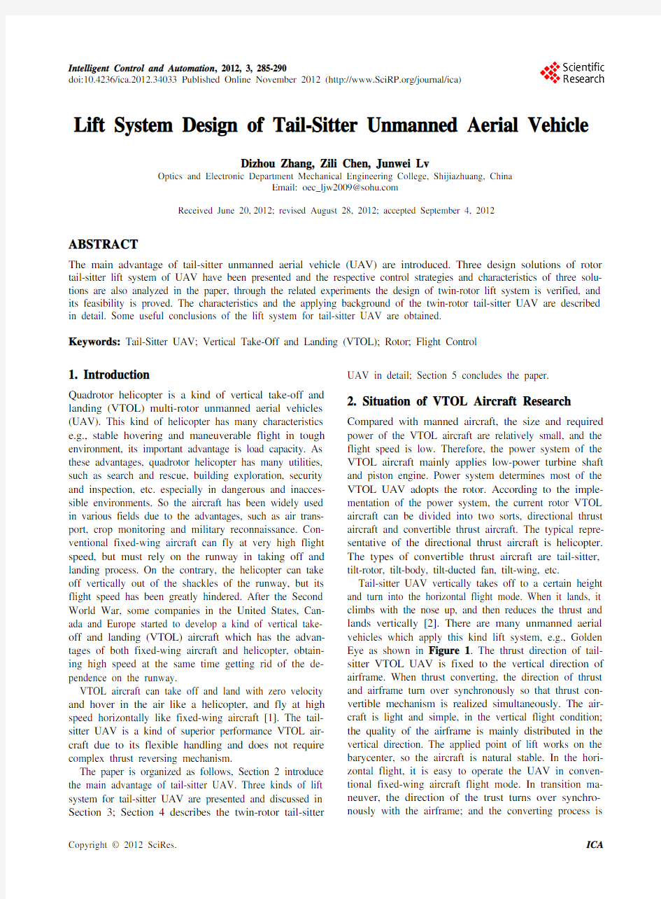
Tail-sitter UAV vertically takes off to a certain height and turn into the horizontal flight mode. When it lands, it climbs with the nose up, and then reduces the thrust and lands vertically [2]. There are many unmanned aerial vehicles which apply this kind lift system, e.g., Golden Eye as shown in Figure 1. The thrust direction of tail- sitter VTOL UAV is fixed to the vertical direction of airframe. When thrust converting, the direction of thrust and airframe turn over synchronously so that thrust con-vertible mechanism is realized simultaneously. The air-craft is light and simple, in the vertical flight condition; the quality of the airframe is mainly distributed in the vertical direction. The applied point of lift works on the barycenter, so the aircraft is natural stable. In the hori-zontal flight, it is easy to operate the UAV in conven-tional fixed-wing aircraft flight mode. In transition ma-neuver, the direction of the trust turns over synchro-nously with the airframe; and the converting process is
D. Z. ZHANG ET AL. 286
simplified into the maneuver of the fixed-wing aircraft.
3. Lift System Program of Tail-Sitter UAV The majority of the Tail-Sitter UAV relies on lift gener-ated by rotors for flight. The lift system involves single rotor and two rotors. Changes of the lift in the size and direction will have a direct impact on the flight of the UAV, so the choice of lift system is very important for aircraft [3]. Here are three system layout programs of tail-sitter UAV’s lift and the control methods of each program in vertical mode, transition maneuver and hori-zontal flight.
3.1. Single-Rotor Tail-Sitter UAV Lift System
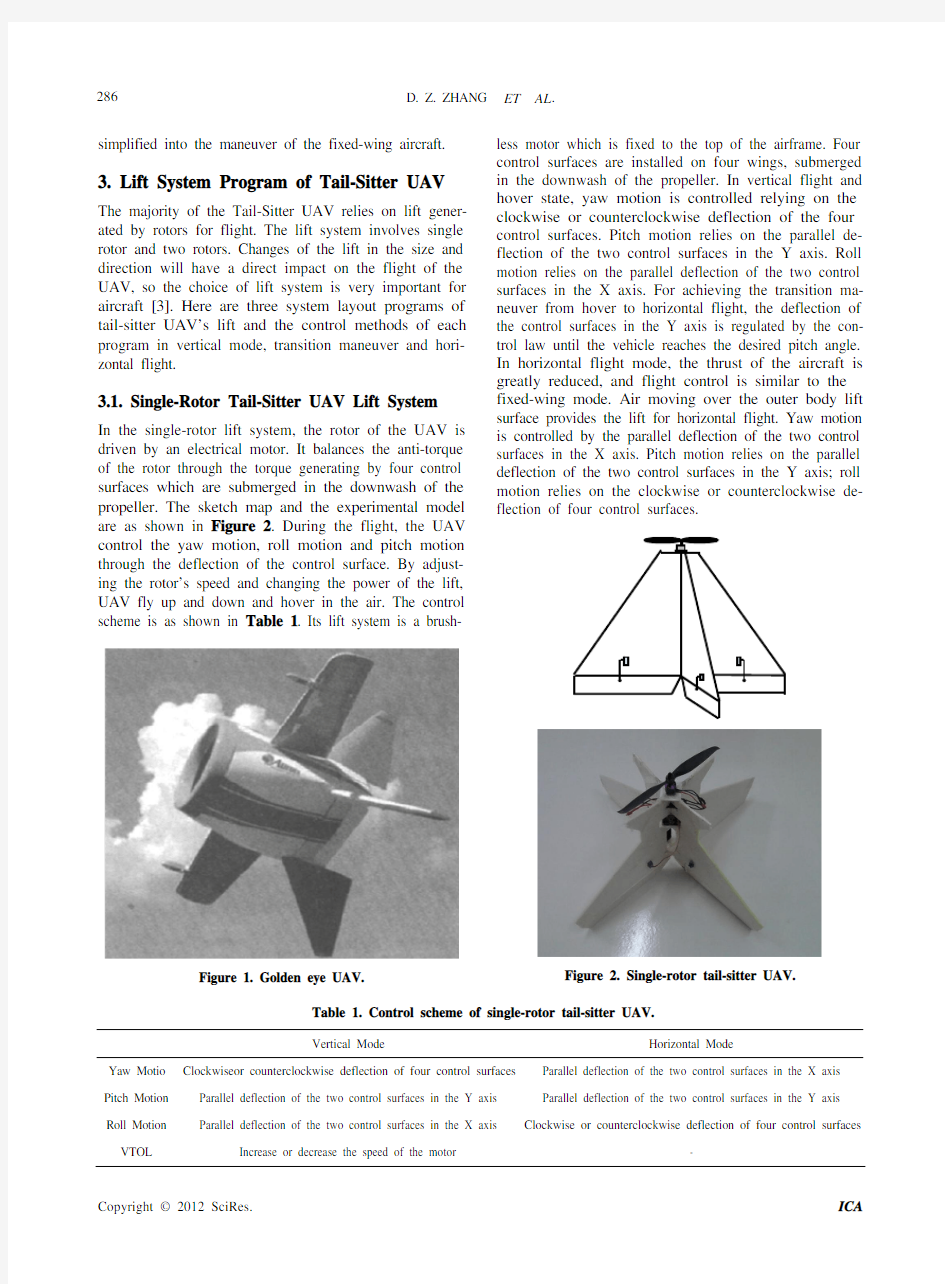
In the single-rotor lift system, the rotor of the UAV is driven by an electrical motor. It balances the anti-torque of the rotor through the torque generating by four control surfaces which are submerged in the downwash of the propeller. The sketch map and the experimental model are as shown in Figure 2. During the flight, the UAV control the yaw motion, roll motion and pitch motion through the deflection of the control surface. By adjust-ing the rotor’s speed and changing the power of the lift, UAV fly up and down and hover in the air. The control scheme is as shown in Table 1. Its lift system is a brush-
Figure 1. Golden eye UAV. less motor which is fixed to the top of the airframe. Four control surfaces are installed on four wings, submerged in the downwash of the propeller. In vertical flight and hover state, yaw motion is controlled relying on the clockwise or counterclockwise deflection of the four control surfaces. Pitch motion relies on the parallel de-flection of the two control surfaces in the Y axis. Roll motion relies on the parallel deflection of the two control surfaces in the X axis. For achieving the transition ma-neuver from hover to horizontal flight, the deflection of the control surfaces in the Y axis is regulated by the con-trol law until the vehicle reaches the desired pitch angle. In horizontal flight mode, the thrust of the aircraft is greatly reduced, and flight control is similar to the fixed-wing mode. Air moving over the outer body lift surface provides the lift for horizontal flight. Yaw motion is controlled by the parallel deflection of the two control surfaces in the X axis. Pitch motion relies on the parallel deflection of the two control surfaces in the Y axis; roll motion relies on the clockwise or counterclockwise de-flection of four control surfaces.
Figure 2. Single-rotor tail-sitter UAV.
Table 1. Control scheme of single-rotor tail-sitter UAV.
Vertical Mode Horizontal Mode
Yaw Motio Clockwiseor counterclockwise deflection of four control surfaces Parallel deflection of the two control surfaces in the X axis Pitch Motion Parallel deflection of the two control surfaces in the Y axis Parallel deflection of the two control surfaces in the Y axis Roll Motion Parallel deflection of the two control surfaces in the X axis Clockwise or counterclockwise deflection of four control surfaces VTOL Increase or decrease the speed of the motor -
D. Z. ZHANG ET AL.287
In the single-rotor lift system, the control surfaces need to be adjusted to balance the anti-torque generated by the single-rotor rotation before taking off, in order to avoid unnecessary deflection of the airframe which is harm to the steady flight of the UAV. The two wings on the X axis play the role of balancing the anti-torque in vertical flight, but in horizontal flight, they don’t gener-ate lift force, but they greatly increase weight of the body.
3.2. Coaxial Dual-Rotor Tail-Sitter UAV Lift
System
Coaxial dual-rotor tail-sitter utilizes a propulsion system having a pair of brushless motor in coaxial configuration, which is shown as Figure 3. It balances the anti-torque of the rotors by the inverse rotating of the two rotors, to stabilize the flight attitude [4]. During the flight, the alti-tude of the UAV is controlled by decreasing or increas-ing the combined thrust of the two propellers. The yaw, pitch and roll motion is controlled via rudder and stabi-lizer installed below the two rotors, and the control scheme is shown in Table 2.
Figure 3. Coaxial dual-rotor tail-sitter UAV.
During the Vertical flight, the vehicle balances the anti-torque precisely by regulating the speed of the two motors to stabilize the flight attitude. Differential veloc-ity of the two motors can control the yaw motion of the aircraft. Pitch motion of this configuration is controlled via the deflection of horizontal stabilizer. To control the roll motion, the aircraft moves the rudder. Converted from the vertical mode to the horizontal flight, the de-flection of horizontal stabilizer is regulated until the UAV reaches the desired angle. During the horizontal mode, the aircraft is airborne and the forward motion is attained-air moving over the outer body wings and pro-vides the lift for horizontal flight. In horizontal flight; the yaw motion is controlled by the rudder which provides the direction of the aircraft. When Pitch motion is changed to horizontal stabilizer motion, Roll motion is controlled by the differential velocity of the two motors and the vehicle thrust is regulated by the velocity of the propulsion system.
In coaxial dual-rotor lift system, the two motors are installed in the same axis direction precisely, and the speed difference between the two motors needs to be controlled within an allowable range. There are also higher requirements in the mechanical installation and control Alpha. However, in this lift system, if one motor failure, the aircraft can rely on the other motor to con-tinue the flight through using the rudder to balance the anti-torque generated by the motor.
3.3. Twins-Rotor Tail-Sitter UAV Lift System
In the twin-rotor tail-sitter UAV Lift System, there are two brushless motors on the top of the airframe [5] as Shown in Figure 4. The motors rotate inversely to bal-ance the anti-torque of each rotor. Decreasing or in-creasing the combined thrust of the two rotors could con-trol the flight attitude. Two ailerons are installed under the two rotors. Yaw, pitch and roll motion of the aircraft are controlled through the deflection of ailerons and ad-justing the speed of the two motors.
In the Vertical flight mode, the UAV balances the anti-torque precisely by regulating the speed of the two motors, to stabilize the flight attitude. Yaw motion is controlled through the Differential deflection of the two ailerons; while to control the pitch motion, two ailerons need to deflect in parallel. Differential velocity of the
Table 2. Control scheme of coaxial dual-rotor tail-sitter UAV.
VerticalMode Horizontal
Mode Yaw Motion Differential velocity of the two motors Rudde
Pitch Motion Stabilizer Stabilizer
Roll Motion Rudde Differential velocity of the Two motors VTOL Increase or decrease the combined thrust of the two motors-
D. Z. ZHANG ET AL. 288
two motors can control the roll motion of the aircraft. Decreasing or increasing the combined thrust of the two rotors could control the flight attitude. Converted from the vertical mode to the horizontal flight, the deflection of two ailerons is regulated until the UAV reaches the desired angle. In the horizontal mode, when forward mo-tion of the aircraft is attained-air moving over the outer body wings provides the lift for horizontal flight. During horizontal flight, the yaw motion is controlled by the differential velocity of the two motors. Pitch motion is controlled by the parallel deflection of the two ailerons. Roll motion is controlled through differential deflection of the two ailerons. The vehicle thrust is regulated by the velocity of the propulsion system (See Table 3).
In the twin-rotor lift system, two motors need to be in-stalled symmetrically in Z axis direction, and the speed of the two motors are required to controlled precisely, in order to stabilize the aircraft in flight. If one motor fails during the flight, the aircraft can’t continue the flight relying on the other motor.
Figure 4. Twin-rotor tail-sitter UAV. 4. Twin-Rotor Experimental Model of UAV According to the analysis and comparison of the three kinds of lift system above mentioned. The twin-rotor lift system can provide greater lift power compared with the
single-rotor. Meanwhile, compared to the coaxial dual-
rotor, the twin-rotor is relatively simple in terms of me-chanical installation .So we finally decide to adopt the twin-rotor lift system to manufacture an experimental UAV model. The well-made twin-rotor tail-sitter UAV is shown in Figure 5.
The airframe of the UAV is built of polystyrene foam sheet, and the vehicle is powered by propulsion systems which consists of two brushless motors juxtaposed on the airframe, which drive a pair of propellers of 90 × 50 in. The motor were driven by two 30A electronic speed con-trollers (ESC), and the power is provided by a Li-Poly battery. At the bottom of the airframe, two ailerons are installed under the downwash of the propellers. The de-flection of the rudders is controlled by two servos, which is used to control the pitch and yaw motion of the aircraft in vertical flight. Parameters of this aircraft are shown in Table 4.
An inertial measurement unit (IMU) is placed in the UAV in order to measure the aircraft motion, which con-sists of three-axis digital gyroscope (L3G4200D), three- axis digital accelerometer (ADXL345) and three-axis Figure 5. Well-made twin-rotor experimental UAV model.
Table 3. Control scheme of twin-rotor tail-sitter UAV.
Vertical Mode Horizontal Mode
Yaw Motion Differential deflection of the two ailerons Differential velocity of the two motors Pitch Motion Parallel deflection of the two ailerons Parallel deflection of the two ailerons Roll Motion Differential velocity of the two motors Differential
deflection of the two ailerons VTOL Increase or decrease the combined thrust of the two motors -
D. Z. ZHANG ET AL.289
Table 4. Parameters of the twin-rotor tail-sitter UAV.
Parameter Value
Airfoil shape Plate
Wing chord 0.5 m
Wing span 0.75 m
Aspect ratio 1.5
Thickness 0.007
Wing area 0.37 m2
Mass vehicle 0.73 kg
digital magnetometers (HMC5883L).
An inertial measurement unit (IMU) is placed in the
UAV in order to measure the aircraft motion, which con-
sists of three-axis digital gyroscope (L3G4200D), three- axis digital accelerometer (ADXL345) and three-axis digital magnetometers (HMC5883L).The MCU (at-mage328) receives and processes the data from the IMU in order to obtain a suitable control [6]. The MCU con-verts the flight information from the IMU into control signals for the motors and severs to control the flight speed of the UAV and the yaw, pitch and roll motion [7]. In Figure 6, (a) the aircraft is in the hover mode, (b) the aircraft is in horizontal flight. The aircraft finally can achieve the given height hover and high-speed horizontal flight under the suitable control law.
5. Conclusions
The experimental results show that the twin-rotor tail-sitter UAV can provide large lift power and its flight attitude is flexible. During the vertical flight, the UAV can be controlled like a helicopter, and the transition maneuver from vertical to horizontal mode is quit easy control by the two ailerons deflecting in parallel. In the horizontal flight, the aircraft is controlled as an airborne. The twin-rotor lift system of the experimental UAV model is well designed and the mechanical installation of it is simple. The overall structure of the UAV is compact and flexible operated.
Although the flight experiment of the twin-rotor tail- sitter UAV has been initially completed, but its automatic control law is far more complex than the common fixed- wing aircraft and the accuracy requirements of attitude estimate is extraordinary higher. Therefore, future work should l be mainly focused on the research of control law. In addition, more sensors need to be added to the aircraft to achieve the navigation of autonomous flight. When incorporating GPS navigation and vision-based naviga-tion [8], UAV will be controlled automatically taking off and landing in the urban environment, and complete the task of trajectory tracking and indoor vertical flight.
After the text edit has been completed, the paper is
(a)
(b)
Figure 6. Twin-rotor experimental UAV model in Hover mode.
ready for the template. Duplicate the template file by using the Save As command, and use the naming con-vention prescribed by your journal for the name of your paper. In this newly created file, highlight all of the con-tents and import your prepared text file. You are now ready to style your paper.
REFERENCES
[1] D. L. Kohlman, “Introduction to V/STOL Airplanes,”
Iowa State University Press, 1981.
[2]H. Stone, “Aerodynamic Modelling of a Wing-in-Slip-
stream Tail-Sitter UAV,” 2002 Biennial International Powered Lift Conference and Exhibit, Williamsburg, 5-7 November 2002.
[3]M. A.·GokhanInalhan, “Design Methodology of a Hybrid
Propulsion Driven Electric Powered Miniature Tailsitter Unmanned Aerial Vehicle,” Journal of Intelligent and Robotic Systems, Vol. 57, 2010, pp. 505-529.
doi:10.1007/s10846-009-9368-0
[4]J. Escareno, A. Sanchez, O. Garcia and R. Lozano, “Mo-
D. Z. ZHANG ET AL. 290
deling and Global Control of the Longitudinal Dynamics of a Coaxial Convertible Mini-UAV in Hover Mode,”
Journal of Intelligent and Robotic Systems, Vol. 54, 2009, pp. 261-273. doi:10.1007/s10846-008-9265-y
[5]J. Escareno, S. Salazar and R. Lozano, “Modelling and
Control of a Convertible VTOL Aircraft,” Proceedings of the 45th IEEE Conference on Decision & Control, San Diego, 13-15 December 2006.
[6]J. Escareno, S. Salazar-Cruz and R. Lozano, “Embedded
Control of a Four-Rotor UAV,” Proceedings of the 2006 American Control Conference, Minneapolis, 14-16 June 2006.
[7]R. H. Stone, “Control Architecture for a Tail-Sitter Un-
manned Air Vehicle,” 5th Asian Control Conference,
Melbourne, 20-23 July 2004.
[8]P. T. Millet, “Vision-Based Precision Landings of a Tail-
sitter UAV,” Master’s Thesis, Brigham Young University, 2010.
复合材料与工程专业毕业设计外文文献翻译
毕业设计外文资料翻译 题目POLISHING OF CERAMIC TILES 抛光瓷砖 学院材料科学与工程 专业复合材料与工程 班级复材0802 学生 学号20080103114 指导教师 二〇一二年三月二十八日
MATERIALS AND MANUFACTURING PROCESSES, 17(3), 401–413 (2002) POLISHING OF CERAMIC TILES C. Y. Wang,* X. Wei, and H. Yuan Institute of Manufacturing Technology, Guangdong University ofTechnology, Guangzhou 510090, P.R. China ABSTRACT Grinding and polishing are important steps in the production of decorative vitreous ceramic tiles. Different combinations of finishing wheels and polishing wheels are tested to optimize their selection. The results show that the surface glossiness depends not only on the surface quality before machining, but also on the characteristics of the ceramic tiles as well as the performance of grinding and polishing wheels. The performance of the polishing wheel is the key for a good final surface quality. The surface glossiness after finishing must be above 208 in order to get higher polishing quality because finishing will limit the maximum surface glossiness by polishing. The optimized combination of grinding and polishing wheels for all the steps will achieve shorter machining times and better surface quality. No obvious relationships are found between the hardness of ceramic tiles and surface quality or the wear of grinding wheels; therefore, the hardness of the ceramic tile cannot be used for evaluating its machinability. Key Words: Ceramic tiles; Grinding wheel; Polishing wheel
《自动化专业英语》中英文翻译-中文部分
第二部分 控制理论 第1章 1.1控制系统的引入 人类控制自然力量的设计促进人类历史的发展,我们已经广泛的能利用这种量进行在人类本身力量之外的物理进程?在充满活力的20世纪中,控制系统工程的发展已经使得很多梦想成为了现实?控制系统工程队我们取得的成就贡献巨大?回首过去,控制系统工程主要的贡献在机器人,航天驾驶系统包括成功的实现航天器的软着陆,航空飞机自动驾驶与自动控制,船舶与潜水艇控制系统,水翼船?气垫船?高速铁路自动控制系统,现代铁路控制系统? 以上这些类型的控制控制系统和日常生活联系紧密,控制系统是一系列相关的原件在系统运行的基础上相互关联的构成的,此外控制系统存在无人状态下的运行,如飞机自控驾驶,汽车的巡航控制系统?对于控制系统,特别是工业控制系统,我们通常面对的是一系列的器件,自动控制是一个复合型的学科?控制工程师的工作需要具有力学,电子学,机械电子,流体力学,结构学,无料的各方面的知识?计算机在控制策略的执行中具有广泛的应用,并且控制工程的需求带动了信息技术的与软件工程的发展? 通常控制系统的范畴包括开环控制系统与闭环控制系统,两种系统的区别在于是否在系统中加入了闭环反馈装置? 开环控制系统 开环控制系统控制硬件形式很简单,图2.1描述了一个单容液位控制系统, 图2.1单容液位控制系统 我们的控制目标是保持容器的液位h 在水流出流量V 1变化的情况下保持在一定 可接受的范围内,可以通过调节入口流量V 2实现?这个系统不是精确的系统,本系 统无法精确地检测输出流量V 2,输入流量V 1以及容器液位高度?图2.2描述了这 个系统存在的输入(期望的液位)与输出(实际液位)之间的简单关系, 图2.2液位控制系统框图 这种信号流之间的物理关系的描述称为框图?箭头用来描述输入进入系统,以及
矫直机中英文对照外文翻译文献
中英文资料翻译 原文: AUTOMATING THE CONTROL OF MODERN EQUIPMENT FOR STRAIGHTENING FLAT-ROLLED PRODUCTS The company Severstal’ completed the successful introduction of new in-line plate-straightening machines (PSMs) on its 2800 and 5000 mills in August 2003 [1, 2, 3]. The main design features of the machines are as follows: ●each machine is equipped with hydraulic hold-down mechanisms (to improve the dynamics and accuracy of the machine adjustments and more reliably maintain a constant gap); ●the machines have mechanisms to individually adjust each work roller with the aid of hydraulic cylinders (this broadens the range of straightening regimes that can be realized by providing a measure of control over the change in the curvature of the plate); ●each work roller is provided with its own adjustable drive (to eliminate rigid kinematic constraints between the spindles); ●the system of rollers of the PSM is enclosed in cassettes (to facilitate repairs and reduce roller replacement costs); ●the PSM has a system that can be used to adjust the machine from a nine-roller straightening scheme to a five- ●roller scheme in which the distance between the rollers is doubled (this is done to widen the range of plate thick-nesses that the machine can accomodate). Thus, the new straightening machine is a sophisticated multi-function system of mechanisms that includes a wide range of hydraulically and electrically driven components controlled by digital and analog signals. The entire complex of PSM mechanisms can be divided into two functional groups: the main group, which includes the mechanisms that partici-pate directly in the straightening operation (the hold-down mechanisms, the mechanisms that individually adjust the rollers,the mechanisms that adjust the components for different straightening regimes, the mechanism that moves the top roller of the feeder, and the main drive); the auxiliary group (which includes the cassette replacement mechanism, the
外文翻译
Load and Ultimate Moment of Prestressed Concrete Action Under Overload-Cracking Load It has been shown that a variation in the external load acting on a prestressed beam results in a change in the location of the pressure line for beams in the elastic range.This is a fundamental principle of prestressed construction.In a normal prestressed beam,this shift in the location of the pressure line continues at a relatively uniform rate,as the external load is increased,to the point where cracks develop in the tension fiber.After the cracking load has been exceeded,the rate of movement in the pressure line decreases as additional load is applied,and a significant increase in the stress in the prestressing tendon and the resultant concrete force begins to take place.This change in the action of the internal moment continues until all movement of the pressure line ceases.The moment caused by loads that are applied thereafter is offset entirely by a corresponding and proportional change in the internal forces,just as in reinforced-concrete construction.This fact,that the load in the elastic range and the plastic range is carried by actions that are fundamentally different,is very significant and renders strength computations essential for all designs in order to ensure that adequate safety factors exist.This is true even though the stresses in the elastic range may conform to a recognized elastic design criterion. It should be noted that the load deflection curve is close to a straight line up to the cracking load and that the curve becomes progressively more curved as the load is increased above the cracking load.The curvature of the load-deflection curve for loads over the cracking load is due to the change in the basic internal resisting moment action that counteracts the applied loads,as described above,as well as to plastic strains that begin to take place in the steel and the concrete when stressed to high levels. In some structures it may be essential that the flexural members remain crack free even under significant overloads.This may be due to the structures’being exposed to exceptionally corrosive atmospheres during their useful life.In designing prestressed members to be used in special structures of this type,it may be necessary to compute the load that causes cracking of the tensile flange,in order to ensure that adequate safety against cracking is provided by the design.The computation of the moment that will cause cracking is also necessary to ensure compliance with some design criteria. Many tests have demonstrated that the load-deflection curves of prestressed beams are approximately linear up to and slightly in excess of the load that causes the first cracks in the tensile flange.(The linearity is a function of the rate at which the load is applied.)For this reason,normal elastic-design relationships can be used in computing the cracking load by simply determining the load that results in a net tensile stress in the tensile flange(prestress minus the effects of the applied loads)that is equal to the tensile strength of the concrete.It is customary to assume that the flexural tensile strength of the concrete is equal to the modulus of rupture of the
英文翻译 机械自动化类
Mechatronics Electrical machinery and electronics, also known as the integration of science, English as Mechatronics, it is by English mechanics of the first half of Mechanics and Electronics of the latter part of a combination of Electronics. Mechatronics 1971, first appeared in Japanese magazine, "Machine Design" on the supplement, with the mechanical-electrical integration of the rapid development of technology, electromechanical integration, the concept was widely accepted and we have universal application. With the rapid development of computer technology and extensive application of mechatronics technology unprecedented development. Mechatronics present technology, mechanical and micro-electronics technology is closely a set of technologies, the development of his machine has been cold humane, intelligent. Specific mechanical and electrical integration technologies, including the following: (1) mechanical engineering machinery and technology is the basis of mechatronics, mechanical technology, focused on how to adapt to mechanical and electrical integration technologies, the use of other high and new technology to update the concept, the realization of the structure, materials, the performance changes to meet the needs to reduce weight, reduce the size and improve accuracy, increase the stiffness and improving the performance requirements. Mechatronic systems in the manufacturing process, the classical theory and technology of mechanical computer-aided technology should help, while the use of artificial intelligence and expert systems, the formation of a new generation of mechanical manufacturing technology. (2) Computer and Information Technology Which information exchange, access, computing, judge and decision-making, artificial intelligence techniques, expert system technology, neural networks are computer information processing technology. (3) System Technology System technology that is the concept of the overall application of related technology organizations, from the perspective of the overall objectives and systems will be interconnected into the overall number of functional units, system interface technology is an important aspect of technology, it is an organic part of the realization of system guarantee connectivity.
建筑学毕业专业外文翻译文献doc资料
本科毕业设计(外文翻译) 题目居住区交往空间规划与设计 院(系部)xxx学院 专业名称xx 年级班级xx 学生姓名xx 指导教师xx xx 年xx 月x 日 Planning and Design of Association Space of residential District
Xia dong liang 【Abstract】:The association space refers to the indoor and outdoor space for communication between residents.The article presents an overall discussion of the necessity,hierarchy and functionality of association space,with a wish to create positive and healthy association atmosphere and stimulate good communication among residents so that the residential area can become a homeland full of love and harmony. 【Keyword】:residential area;association space;necessity;hierarchy;Functionality 【Foreword】:As the housing system reform and the rapid development of real estate, urban residential areas large urban settlements have emerged on the layout of residential buildings, public buildings, public green space, life and living facilities such as roads, to provide urban residents live in the community and The establishment, is an integral part of the city. Exchanges between the living room area residents is to communicate and exchange of indoor and outdoor space. At this stage, people's living standards greatly improved the living environment of continuous improvement district. Developers should not only focus on residential construction and the reasonable comfort, paying greater attention to the construction of residential environment. However, the current environment in the construction of residential areas, they are often the natural ecology of greening the environment is much more to consider, and the promotion of exchanges between the residents of the space environment to consider less, environmental construction can not meet the occupants of the psychological characteristics and needs. From the basic physiological needs gradually to meet the psychological and cultural fields of promoting a higher level, the residential area is not only the function of living, but also people's thinking and feelings of the local exchange. Therefore, the strengthening of exchanges between the residential areas of space construction, increase residential neighbourhood affinity, should be developed in the planning and construction of residential areas should also consider the issue. How to conduct exchanges between the residential areas of space planning and design, improve people's quality of life, the author of his own real estate development
电气工程及其自动化专业_外文文献_英文文献_外文翻译_plc方面
1、 外文原文 A: Fundamentals of Single-chip Microcomputer Th e si ng le -c hi p m ic ro co mp ut er i s t he c ul mi na ti on of both t h e de ve lo pm en t o f t he d ig it al co m pu te r an d th e i n te gr at ed c i rc ui t a rg ua bl y t h e to w m os t s ig ni f ic an t i nv en ti on s o f t he 20th c e nt ur y [1]. Th es e t ow ty pe s of ar ch it ec tu re a re fo un d i n s in g le -ch i p m i cr oc om pu te r. So m e em pl oy t he spl i t pr og ra m/da ta m e mo ry o f th e H a rv ar d ar ch it ect u re , sh ow n in Fi g.3-5A -1, o th ers fo ll ow t he p h il os op hy , wi del y a da pt ed f or ge n er al -p ur po se co m pu te rs a nd m i cr op ro ce ss o r s, o f ma ki ng n o log i ca l di st in ct ion be tw ee n p r og ra m an d d at a m e mo ry a s i n t he P r in ce to n ar ch ite c tu re , sh ow n i n F ig.3-5A-2. In g en er al te r ms a s in gl e -chi p m ic ro co mp ut er i s c h ar ac te ri ze d b y t h e i nc or po ra ti on o f a ll t he un it s of a co mp uter i n to a s in gl e d ev i ce , as s ho wn in Fi g3-5A -3. Fig.3-5A-1 A Harvard type Program memory Data memory CPU Input& Output unit memory CPU Input& Output unit
有关隧道方面外文文献与翻译
A convection-conduction model for analysis of the freeze-thaw conditions in the surrounding rock wall of a tunnel in permafrost regions HE Chunxiong( 何春雄 ), (State Key Laboratory of Frozen Soil Engineering, Lanzhou Institute of Glaciology and Geocryology, Chinese Academy of Sciences, Lanzhou 730000, China; Department of Applied Mathematics, South China University of Technology, Guangzhou 510640, China) WU Ziwang( 吴紫汪 )and ZHU Linnan( 朱林楠 ) (State key Laboratory of Frozen Soil Engineering, Lanzhou Institute of Glaciology and Geocryology Chinese Academy of Sciences, Lanzhou 730000, China) Received February 8, 1999 Abstract Based on the analyses of fundamental meteorological and hydrogeological conditions at the site of a tunnel in the cold regions, a combined convection-conduction model for air flow in the tunnel and temperature field in the surrounding has been constructed. Using the model, the air temperature distribution in the Xiluoqi No. 2 Tunnel has been simulated numerically. The simulated results are in agreement with the data observed. Then, based on the in situ conditions of sir temperature, atmospheric pressure, wind force, hydrogeology and engineering geology, the air-temperature relationship between the temperature on the surface of the tunnel wall and the air temperature at the entry and exit of the tunnel has been obtained, and the freeze-thaw conditions at the Dabanshan Tunnel which is now under construction is predicted. Keywords: tunnel in cold regions, convective heat exchange and conduction, freeze-thaw. A number of highway and railway tunnels have been constructed in the permafrost regions and their neighboring areas in China. Since the hydrological and thermal
毕业设计外文翻译资料
外文出处: 《Exploiting Software How to Break Code》By Greg Hoglund, Gary McGraw Publisher : Addison Wesley Pub Date : February 17, 2004 ISBN : 0-201-78695-8 译文标题: JDBC接口技术 译文: JDBC是一种可用于执行SQL语句的JavaAPI(ApplicationProgrammingInterface应用程序设计接口)。它由一些Java语言编写的类和界面组成。JDBC为数据库应用开发人员、数据库前台工具开发人员提供了一种标准的应用程序设计接口,使开发人员可以用纯Java语言编写完整的数据库应用程序。 一、ODBC到JDBC的发展历程 说到JDBC,很容易让人联想到另一个十分熟悉的字眼“ODBC”。它们之间有没有联系呢?如果有,那么它们之间又是怎样的关系呢? ODBC是OpenDatabaseConnectivity的英文简写。它是一种用来在相关或不相关的数据库管理系统(DBMS)中存取数据的,用C语言实现的,标准应用程序数据接口。通过ODBCAPI,应用程序可以存取保存在多种不同数据库管理系统(DBMS)中的数据,而不论每个DBMS使用了何种数据存储格式和编程接口。 1.ODBC的结构模型 ODBC的结构包括四个主要部分:应用程序接口、驱动器管理器、数据库驱动器和数据源。应用程序接口:屏蔽不同的ODBC数据库驱动器之间函数调用的差别,为用户提供统一的SQL编程接口。 驱动器管理器:为应用程序装载数据库驱动器。 数据库驱动器:实现ODBC的函数调用,提供对特定数据源的SQL请求。如果需要,数据库驱动器将修改应用程序的请求,使得请求符合相关的DBMS所支持的文法。 数据源:由用户想要存取的数据以及与它相关的操作系统、DBMS和用于访问DBMS的网络平台组成。 虽然ODBC驱动器管理器的主要目的是加载数据库驱动器,以便ODBC函数调用,但是数据库驱动器本身也执行ODBC函数调用,并与数据库相互配合。因此当应用系统发出调用与数据源进行连接时,数据库驱动器能管理通信协议。当建立起与数据源的连接时,数据库驱动器便能处理应用系统向DBMS发出的请求,对分析或发自数据源的设计进行必要的翻译,并将结果返回给应用系统。 2.JDBC的诞生 自从Java语言于1995年5月正式公布以来,Java风靡全球。出现大量的用java语言编写的程序,其中也包括数据库应用程序。由于没有一个Java语言的API,编程人员不得不在Java程序中加入C语言的ODBC函数调用。这就使很多Java的优秀特性无法充分发挥,比如平台无关性、面向对象特性等。随着越来越多的编程人员对Java语言的日益喜爱,越来越多的公司在Java程序开发上投入的精力日益增加,对java语言接口的访问数据库的API 的要求越来越强烈。也由于ODBC的有其不足之处,比如它并不容易使用,没有面向对象的特性等等,SUN公司决定开发一Java语言为接口的数据库应用程序开发接口。在JDK1.x 版本中,JDBC只是一个可选部件,到了JDK1.1公布时,SQL类包(也就是JDBCAPI)
自动化外文翻译
景德镇陶瓷学院 毕业设计(论文)有关外文翻 译 院系:机械电子工程学院 专业:自动化 姓名:肖骞 学号: 201010320116 指导教师:万军 完成时间: 2014.5.8 说明
1、将与课题有关的专业外文翻译成中文是毕业设计(论文)中的一个不可缺少的环节。此环节是培养学生阅读专业外文和检验学生专业外文阅读能力的一个重要环节。通过此环节进一步提高学生阅读专业外文的能力以及使用外文资料为毕业设计服务,并为今后科研工作打下扎实的基础。 2、要求学生查阅与课题相关的外文文献3篇以上作为课题参考文献,并将其中1篇(不少于3000字)的外文翻译成中文。中文的排版按后面格式进行填写。外文内容是否与课题有关由指导教师把关,外文原文附在后面。 3、指导教师应将此外文翻译格式文件电子版拷给所指导的学生,统一按照此排版格式进行填写,完成后打印出来。 4、请将封面、译文与外文原文装订成册。 5、此环节在开题后毕业设计完成前完成。 6、指导教师应从查阅的外文文献与课题紧密相关性、翻译的准确性、是否通顺以及格式是否规范等方面去进行评价。 指导教师评语: 签名: 年月日
TMS320LF2407, TMS320LF2406, TMS320LF2402 TMS320LC2406, TMS320LC2404, MS320LC2402 DSP CONTROLLERS The TMS320LF240x and TMS320LC240x devices, new members of the ‘24x family of digital signal processor (DSP) controllers, are part of the C2000 platform of fixed-point DSPs. The ‘240x devices offer the enhanced TMS320 architectural design of the ‘C2xx core CPU for low-cost, low-power, high-performance processing capabilities. Several advanced peripherals, optimized for digital motor and motion control applications, have been integrated to provide a true single chip DSP controller. While code-compatible with the existing ‘24x DSP controller devices, the ‘240x offers increased processing performance (30 MIPS) and a higher level of peripheral integration. See the TMS320x240x device summary section for device-specific features. The ‘240x family offers an array of memory sizes and different peripherals tailored to meet the specific price/performance points required by various applications. Flash-based devices of up to 32K words offer a reprogrammable solution useful for: ◆Applications requiring field programmability upgrades. ◆Development and initial prototyping of applications that migrate to ROM-based devices. Flash devices and corresponding ROM devices are fully pin-to-pin compatible. Note that flash-based devices contain a 256-word boot ROM to facilitate in-circuit programming. All ‘240x devices offer at least one event manager module which has been optimized for digital motor control and power conversion applications. Capabilities of this module include centered- and/or edge-aligned PWM generation, programmable deadband to prevent shoot-through faults, and synchronized analog-to-digital conversion. Devices with dual event managers enable multiple motor and/or converter