飞秒激光器的应用
Industrial femtosecond lasers and material processing
01/22/2019
NORMAN HODGSON, MICHAEL LAHA, TONY S. LEE, ALBRECHT STEINKOPFF, and SEBASTIAN HEMING
Over the last five years, material processing with femtosecond pulses in the range of 300 to 900 fs has gained in popularity due to the small heat-affected zone (HAZ) and increased energy penetration depth resulting from the high laser pulse intensity. Industrial ultrashort-pulse (USP) diode-pumped solid-state and fiber lasers are now being used to cut foils for flat panel displays, to cut stents, and to drill fuel injector nozzles, as well as for wafer scribing and surface microstructuring.
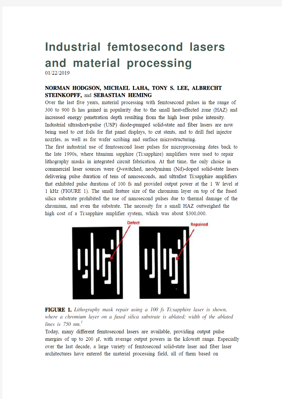
The first industrial use of femtosecond laser pulses for microprocessing dates back to the late 1990s, where titanium sapphire (Ti:sapphire) amplifiers were used to repair lithography masks in integrated circuit fabrication. At that time, the only choice in commercial laser sources were Q-switched, neodymium (Nd)-doped solid-state lasers delivering pulse duration of tens of nanoseconds, and ultrafast Ti:sapphire amplifiers that exhibited pulse durations of 100 fs and provided output power at the 1 W level at 1 kHz (FIGURE 1). The small feature size of the chromium layer on top of the fused silica substrate prohibited the use of nanosecond pulses due to thermal damage of the chromium, and even the substrate. The necessity for a small HAZ outweighed the high cost of a Ti:sapphire amplifier system, which was about $300,000.
FIGURE 1. Lithography mask repair using a 100 fs Ti:sapphire laser is shown, where a chromium layer on a fused silica substrate is ablated; width of the ablated lines is 750 nm.1
Today, many different femtosecond lasers are available, providing output pulse energies of up to 200 μJ, with average output powers in the kilowatt range. Especially over the last decade, a large variety of femtosecond solid-state laser and fiber laser architectures have entered the material processing field, all of them based on
ytterbium (Yb)-doped gain materials. Average output powers of up to 100 W are currently employed in industrial applications, with pulse durations between 300 and 900 fs and repetition rates of up to 2 MHz. Compared to the original Ti:sapphire amplifier systems, the output powers have increased by two orders of magnitude, while system cost has been considerably decreased at the same time.
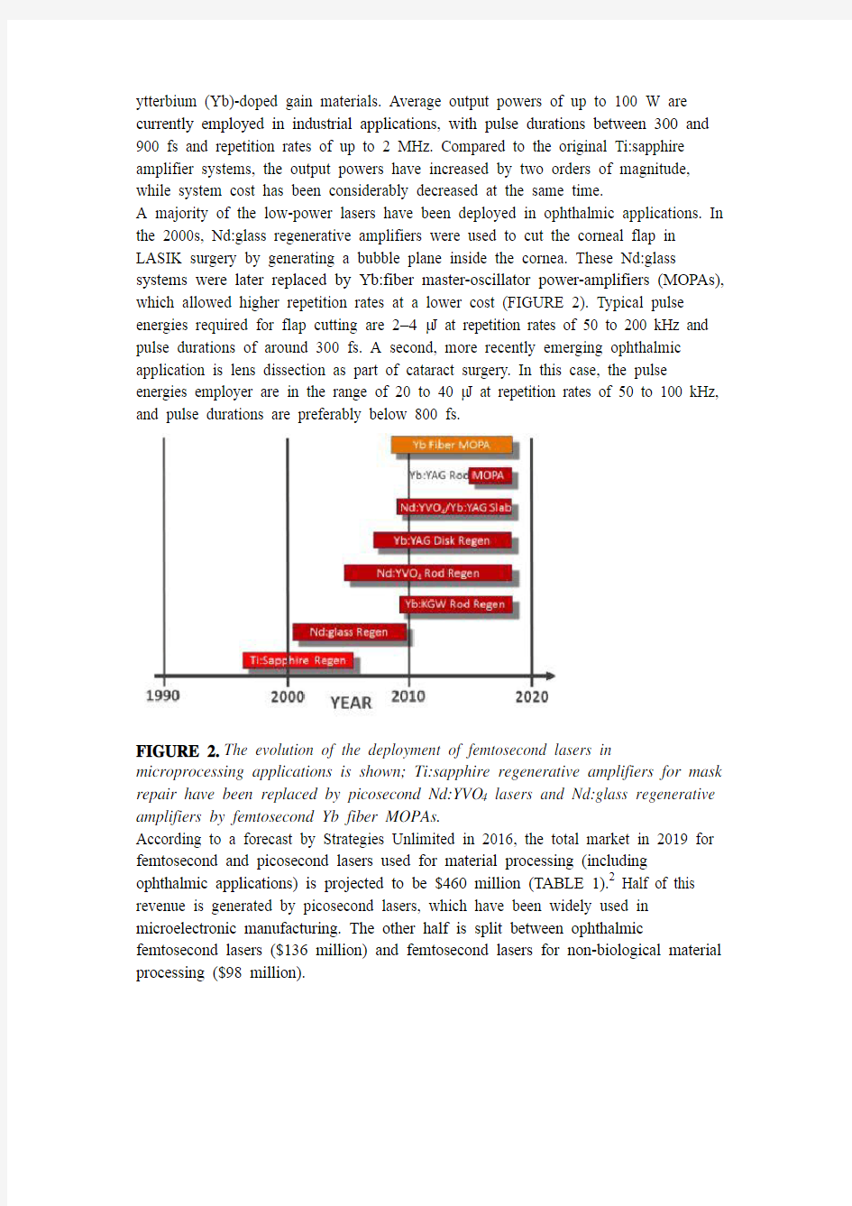
A majority of the low-power lasers have been deployed in ophthalmic applications. In the 2000s, Nd:glass regenerative amplifiers were used to cut the corneal flap in LASIK surgery by generating a bubble plane inside the cornea. These Nd:glass systems were later replaced by Yb:fiber master-oscillator power-amplifiers (MOPAs), which allowed higher repetition rates at a lower cost (FIGURE 2). Typical pulse energies required for flap cutting are 2–4 μJ at repetition rates of 50 to 200 kHz and pulse durations of around 300 fs. A second, more recently emerging ophthalmic application is lens dissection as part of cataract surgery. In this case, the pulse energies employer are in the range of 20 to 40 μJ at repetition rates of 50 to 100 kHz, and pulse durations are preferably below 800 fs.
FIGURE 2.The evolution of the deployment of femtosecond lasers in microprocessing applications is shown; Ti:sapphire regenerative amplifiers for mask repair have been replaced by picosecond Nd:YVO4 lasers and Nd:glass regenerative amplifiers by femtosecond Yb fiber MOPAs.
According to a forecast by Strategies Unlimited in 2016, the total market in 2019 for femtosecond and picosecond lasers used for material processing (including ophthalmic applications) is projected to be $460 million (TABLE 1).2 Half of this revenue is generated by picosecond lasers, which have been widely used in microelectronic manufacturing. The other half is split between ophthalmic femtosecond lasers ($136 million) and femtosecond lasers for non-biological material processing ($98 million).
TABLE 1. The 2016 Revenue Forecast of femtosecond and picosecond lasers in material processing is shown, where values for 2014 and 2015 are actual revenues; femtosecond lasers include ophthalmic lasers.2
Mechanism and benefits of femtosecond laser processing
The interaction of femtosecond and picosecond pulses with matter is governed by the absorption of the light by the electrons and subsequent energy transfer to the lattice. In the case of metals, the photons are absorbed by the electron gas, which increases its temperatures to values of several 10,000°C. The electrons will transfer their energy to the lattice within the electron-phonon relaxation time, which for most materials is in the range of 100 fs to 1 ps at room temperature. The lattice has about 100X higher heat capacity compared to the electrons. This leads to a substantial delay between the incidence of the laser pulse and the time when the lattice has reached melting temperature (FIGURE 3). For high laser fluences, the ablation of the heated material occurs several tens of picoseconds after the laser pulse is absorbed.
FIGURE 3.Interaction of ultrafast pulses with a metal is shown. The electron gas absorbs the laser light, leading to a hot, thermalized electron distribution within 100 fs; the lattice will heat up with a delay of 4 to 30 ps.
The light-matter interaction for ultrashort laser pulses can be mathematically described by the Two-Temperature Model, which provides the temporal and spatial evolution of the temperature of electron gas and lattice by incorporating the coupling between both systems via the electron–phonon relaxation time.3 This model has been used very successfully over the last decades to calculate damage threshold fluence, ablation rates, and HAZ for ultrashort pulse processing (FIGURE 4).4-8 The main results are that for pulses that are shorter than 10 ps, the damage threshold fluence remains constant, while for larger pulse durations, the threshold fluence increases in
proportion to the square-root of the pulse duration, independent of incident laser pulse wavelength.
FIGURE 4.Calculated temporal temperature distribution of electron gas (left) and lattice for copper after irradiation with a 100 fs pulse at an average fluence of 0.14
J/cm2 and a wavelength of 800 nm.7
Similarly, the HAZ remains constant for pulse durations below 10 ps, again independent of the wavelength of the laser light. The basic reason for this behavior is the delay in the temperature increase of the lattice and of heat conduction into the material. This regime of pulsed laser-matter interaction is therefore referred to as cold ablation, since the lattice stays cold during irradiation by the laser pulse. This name is a bit misleading, though, since the material will have to reach melting temperature to induce ablation.
The most interesting effect of ultrashort pulse interaction, however, is the increase in the energy penetration depth and ablation depth with decreasing pulse duration. Decreasing the pulse duration at a given energy fluence leads to an increase in the temperature of the electron gas and a simultaneous increase of the electron-phonon relaxation time.
In a more mechanical model, this can be easily understood: the velocity of the electrons traveling through the lattice can become as high as 100,000 m/s for femtosecond pulses due to the very high intensity, and this high speed results in deeper penetration of the electron into the lattice without transferring energy to the lattice.8
The material processing efficiency and quality depends on the duration of the laser pulses. For pulses in the nanosecond regime, the absorption of the laser pulse is determined by the linear optical absorption depth of the laser light and the energy dissipation is a result of heat conduction into the material (FIGURE 5). For pulses that are shorter than 10 ps, the initial energy penetration depends strongly on the light intensity and leads to deeper penetration depth for femtosecond pulses. In addition, the lack of thermal conduction during the pulse and the time of lattice heating results in a very low HAZ. For metals, HAZ of less than 5 μm can be achieved, while for plastic materials, the HAZ is typically in the range of 30 to 50 μm.
FIGURE 5. Absorption of a laser pulse in a medium is shown, where energy penetration is represented in blue and volume heated via heat conduction in red.
The increase of the penetration depth for shorter pulses leads to an increase in the maximum ablation rates when the pulses become shorter than about 20 ps (as shown in FIGURE 6 for aluminum). As will be discussed subsequently, at any pulse duration the maximum ablation rate is achieved at a pulse fluence of about 7.5X the ablation threshold fluence. Compared to Q-switched laser pulses with pulse durations of tens of nanoseconds, the increased electron velocity in the material leads to ablation rates for sub-picosecond pulses that are only a factor of three lower.
FIGURE 6. Maximum ablation rates of aluminum with Coherent's measured values (red dots) and using values taken from data published by Breitling et al. (blue dots).9 For pulsed lasers, ablation becomes most efficient at a pulse energy fluence equal to e2 times the threshold fluence. This is a result of the saturation of the ablated volume with increasing pulse fluence. At a fixed output power, more volume can therefore be ablated if the energy fluence is lowered, while simultaneously increasing pulse repetition rate and therefore throughput (FIGURE 7). The maximum value is achieved at the optimum fluence. The ablation rate, C (in mm3/W/min), is given by:
where F is the peak fluence in J/mm2, F th is the peak threshold fluence, and d is the energy penetration depth per pulse in millimeters.10 Typical values for the energy penetration depth per pulse are in the range of 20 to 100 nm for metals, semiconductors, and plastics, and >500 nm for glasses and transparent crystals.
FIGURE 7. Ablated volume per pulse (blue curve) and ablated volume per second (green curve) at constant laser power are shown.10
FIGURE 8 shows the measured ablation rates for Nitinol as a function of the average pulse fluence for various pulse durations. Nitinol is used to manufacture stents and requires femtosecond pulses to increase the throughput. The laser was a 1035 nm modelocked fiber MOPA, where the settings of the compressor were changed to implement different pulse durations, and external second- and third-harmonic generation (SHG and THG, respectively) stages could be added to access wavelengths of 517 and 345 nm. A rectangular area of about 0.5 × 1.5 mm was ablated to a depth of about 200 μm using a spot diameter of 20 μm with a spot overlap of 60% in both directions. Decreasing the pulse duration to 400 fs resulted in an increase in the ablation rate by a factor of two compared to 19 ps pulses. This increase in ablation efficiency for femtosecond pulses is common amongst metals and semiconductors. For transparent dielectrics, however, the ablation rate is higher for picosecond pulses. This is due to the lack of free electrons, which requires high threshold fluences to ablate the material. For femtosecond pulses, the resulting peak powers are too high and lead to optical breakdown and decreased ablation rates.
FIGURE 8. Measured ablation rates of Nitinol at 1035 nm as a function of average pulse fluence are shown; the parameter is the pulse duration.
Ablation rates vary with laser wavelength, depending on the absorption spectrum of the material. In general, the ablation rates become higher when the material already has a linear absorption at the incident wavelength.
FIGURE 9 shows steel ablation rates for infrared (IR), green, and ultraviolet (UV). While the ablation rates for the 517 nm laser are 50% higher as compared to IR, there is also a 2X decrease in laser efficiency when converting an IR laser to green emission using extra-cavity SHG. Considering typical conversion efficiencies of 50% and 30% for green and UV generation, respectively, there are not many materials where using harmonic wavelengths will increase the absolute value of the ablation rate. Exceptions are aluminum, Nitinol, and gold for green emission wavelengths, and plastic materials (PET, OLED layers, polarizers, etc.), where UV will lead to increased ablation and better cut quality. In all other cases, the biggest benefit of using harmonic wavelengths is the increased Rayleigh range, which results in an increased depth of field or in smaller kerf widths.
FIGURE 9.Measured ablation rates for steel at different wavelengths as a function of energy fluence and pulse duration are shown.
The comparison of maximum ablation rates for a variety of materials for 10 ps and 400 fs pulses at three different laser wavelengths is presented in FIGURE 10. While there are variations in ablation rates between different wavelengths, the variations are relatively small, and the choice of wavelength is more determined by focusing conditions and the linear absorption of the material. Exceptions are transparent materials that require IR laser wavelengths at pulse durations of tens of picoseconds.
FIGURE 10.Measured maximum ablation rates for various materials at IR, green, and UV laser wavelengths and two different pulse durations of 10 ps/400 fs for IR and green, and 10 ps/500 fs for UV are shown.
Note that the typical ablation rates are on the order of 0.2 mm3/(W min), which means that with a 100 W laser, the equivalent volume of a 10-cent U.S. coin piece can be ablated within about 2 minutes of laser-on time.
Increased throughput with burst mode
One of the challenges of USP laser material processing is that maximum ablation rates are achieved at relatively low average pulse fluences. TABLE 2 provides an overview of the measured optimum (maximum ablation rate) average pulse fluences
for various materials. With the exception of transparent dielectrics, the optimum fluences are on the order of 1 J/cm2 or lower.
TABLE 2.Measured optimum average pulse fluences and maximum ablation rates for 400 fs pulse duration and a wavelength of 1035 nm are shown.
However, achieving these low optimum fluences (and therefore optimum ablation rates) in practice is problematic. For example, a laser with an output power of 50 W at a 500 kHz repetition rate will yield an average energy fluence of 14 J/cm2 at the work surface when focused to a 30 μm spot diameter. Operating at this high fluence results in a much lower ablation rate, as well as an increased HAZ, since the heat-affected area increases with increasing pulse fluence. To approach the optimum fluence, the laser has to be either focused to a 3–5X larger spot size, which in many cases would be too large, or alternately, be operated at 10-20X the repetition rate, which is prohibited by the current scanner technology.
A solution to this problem is provided by operating in so-called seeder burst mode. To understand seeder burst mode, realize that all industrial USP lasers are based on a modelocked seed laser, which typically operates at a repetition rate of about 50 MHz. To produce 500 kHz final output (as in the preceding example), a pulse picker separates out every hundredth pulse and amplifies it. The rest of the pulses are discarded.
In one implementation of seeder burst mode, instead of picking out every hundredth pulse, a train of 3 to 10 pulses, each of which are about 20 ns apart, is utilized. As a result, the individual pulse fluence is reduced by a factor of N, where N is the number of pulses in the burst, while the average power of the laser remains constant (FIGURE 11). This allows operation at, or near, the optimum fluence to produce a substantial increase in ablation rate. Also, note that the pulse separation is sufficient so that, for metals and semiconductors, the lattice returns to its initial temperature between pulses, meaning individual pulses hit the cold target again. This is also true for most glasses, where the workpiece is ‘cold’ after <10 ns.
FIGURE 11.Change in ablation rate at constant laser power by using a burst of 5 seed pulses instead of a single pulse at 200 kHz is shown.
Burst mode has a different effect when cutting deep trenches, as the plasma generated cannot escape and will interact with the subsequent pulse. In this case, there is interaction between the individual laser pulses via absorption in the plasma.11,12 This effect is used with picosecond and femtosecond lasers for filament cutting of glasses, where long filaments with diameters of several microns are generated through a balance of self-focusing and de-focusing after plasma generation (FIGURE 12). Since the plasma lifetime is on the order of 30 ns, a seeder burst mode with seed frequency of 50 MHz or greater will generate an interaction of the next laser pulse with the plasma generated by the previous one, leading to a long chain of focusing and defocusing events inside the material. By placing filaments next to each other, glasses can be cut at speeds of meters per second with thicknesses of up to 5 mm, and surface roughness of <0.3 μm RMS. Filament cutting is used in the automotive and aviation industries to cut window glass and mirror glass.
FIGURE 12.Filament cutting of glass by generating long filaments inside the material via self-focusing and de-focusing by the generated plasma is shown; close
positioning of the filaments leads to smooth cut surfaces with a roughness of <0.3 μm RMS.
Building reliable USP lasers with burst mode
While all industrial femtosecond laser amplifiers are based on Yb-doped crystals or fibers, there are two distinct amplifier architectures used depending on the geometry of the gain materials they employ (FIGURE 13). For amplifiers based on fibers, slabs or multi-rod systems, the gain per pass is high enough to use a MOPA architecture, where a seed laser providing power of tens of milliwatts (for fibers), and several watts for slabs and rods, at repetition rates of around 50 MHz is pulse-picked and then amplified to more than 100 W. The MOPA architecture has several advantages, like operation at high repetition rates up to tens of megahertz, easy implementation of seeder burst mode, and power-scaling by adding additional amplifier stages.
FIGURE 13. The two laser architectures used for industrial femtosecond lasers are MOPA for fibers, slabs, and multi-rod systems (top) and regenerative amplifier for low-gain systems (disks and single rods; bottom); both architectures use CPA.
For amplifiers utilizing Yb:YAG disk lasers and single rods, the gain per pass is too low to get enough amplification of the seed laser, and regenerative amplifiers are used to achieve the 100+ W output power. For Yb:YAG disks, the seed pulses are switched into the amplifier cavity via a Pockels-cell, and the pulse makes about 150 round-trips inside the resonator before the Pockels-cell ejects the high energy pulse again. Regenerative amplifiers are limited in repetition rate to ~1 MHz (due to the
Pockels-cell switching electronics) and it is difficult to implement seeder burst mode in this architecture. For this reason, MOPA architectures have a clear advantage for femtosecond and picosecond material processing (TABLE 3).
TABLE 3. Operating parameters of employed industrial femtosecond lasers are shown; all three systems have a demonstrated power-scaling capability of kilowatts, but only up to 100 W output power is currently being used.
Independent of the amplifier architecture (MOPA or regen), all USP laser systems use chirped pulse amplification (CPA) to stretch and compress the pulse after amplification. A femtosecond laser therefore will also provide picosecond pulses by changing the compressor settings—a distinct advantage when optimizing a given process by varying the pulse duration.
Since 2015, Coherent has offered a family of femtosecond fiber-MOPA-based laser products under the name MONACO. Average powers of up to 60 W, pulse energy of up to 80 μJ, and tunable pulse durations between 300 fs and 10 ps, plus easy access to burst mode operation, make the MONACO lasers the ultimate tool for ultrashort laser processing. Models with green and UV output wavelengths are also available.
FIGURE 14. Industrial applications of femtosecond lasers include injector nozzle cutting, stent cutting, glass filament cutting, and microtexturing of metals. Applications
At present, femtosecond lasers are used in a variety of applications that require the creation of small structures with low HAZ and high quality of the ablated surface areas. While the majority of new femtosecond laser installations are still for ophthalmic applications, the non-biologic material processing market has seen double-digit growth over the last couple of years. Some of the main applications are shown in FIGURE 14. There is particularly strong growth in the semiconductor and display markets, where femtosecond and picosecond lasers are used to cut foils used in flat panel displays (FIGURE 15) and for thin wafer scribing.
FIGURE 15.UV picosecond and femtosecond lasers are used to cut OLED foil; the UV wavelength generates lower HAZ and cleaner cuts in plastic foils as compared to IR laser pulses.
It is estimated that the non-biological microprocessing portion of femtosecond and picosecond laser market will grow at a CAGR of 13%, leading to a total revenue of $675 million in 2025.2 In addition, about $200 million of ophthalmic femtosecond lasers are expected to be sold annually by 2025, representing a 6% CAGR.
Over this time period, higher-power femtosecond lasers providing several hundreds of watts will enter the industrial application space, and new USP processing techniques will emerge, especially for cutting multilayered structures, processing novel compound materials, and laser cutting of smartphone display glass. At present, all smartphone display glasses are cut mechanically using diamond wheels and grinders. Once an all-laser solution for display glass cutting is found (this includes not only cutting the periphery, but also chamfering and cutting the holes for speakers and homing button),13 the growth of industrial femtosecond lasers may far exceed the 13% projected CAGR.
飞秒,皮秒以及纳秒激光器切割固体
飞秒,皮秒以及纳秒激光器溶解固体 摘要:0.2—5000ps激光溶解固体 题目:蓝宝石激光脉冲的开发、模型以及其性质的展示。飞秒激光对精密材料进行加工的优势也进行了讨论和展示。 正文:高效的利用激光对精密材料进行加工离不开对于调解激光辐射与物质之间相互影响的重要规律的知识。为了实现这一目标,激光与物质之间相互影响的系统研究是必要的。由于现在激光系统的进步,尤其是那些基于啁啾脉冲扩展技术,这样系统的研究已经在非常广泛的激光领域成为可能。CPA系统能够使激光脉冲持续时间从大约100飞秒变至几十纳秒,而其他特性不改变。这就允许我们对多种不稳定的激光与物质之间相互影响的过程进行细致的分析。举些例子,最近的学术研究对于损伤阈值、分割阈值以及高强度激光溶解都有提及。这个系统的研究只是刚刚开始,更多的研究将会帮助我们了解和证实飞秒激光系统对于精密材料加工的潜质。 最近进行的一些关于飞秒和纳秒脉冲溶解固体的实验。飞秒激光的染色和受激分子激光系统对精密材料加工的优势已经体现无疑。在这一研究报告中,我们展示了激光溶解和打孔技术的商业用途,蓝宝石激光提供了一个780nm,能量为100mJ,持续时间可在0.2—5000ps进行变化的激光系统。实验处于一个低影响的体系中,在其中,只是很少量的超出蒸发阈值。这个体系对于溶解精密固体实验意义非凡,这样一来,固体内的能量沉积和热影响区域都会被降到最低。我们讨论和举例飞秒激光脉冲的优点,希望能刺激在这个领域新的研
究。第一部分中,我们将展示三种不同持续时间的脉冲在低影响条件下溶解金属的特点:飞秒,皮秒以及纳秒激光器这三种实验对象。关于实验的配置和结果,我们将在第二部分中给出。 1、理论知识背景 在低强度的短波激光脉冲作用于金属物时,由于反方向的韧制辐射,激光的能量会被自由电子吸收。然后,被吸收的激光能量需要在电子系统中热能化,将能量传输到晶格中,由于电子的热量传输给了溶解目标,导致能量流失。如果我们假定,在电子系统中的热能化是非常快而且其电子和晶格系统都以热量为表征( T&i T),那么能量 e 进入金属中的过程就可描述为一维下,以两个温度为变化量的扩散模型: 在上式中,z为与固体目标表面垂直的一个分量,Q(z)是热流量,S为激光加热源项,I(t)是激光光强,A=1-R和α分别是材料表面透射率和材料的吸收常数, C和i C分别是电子和晶格系统的单位 e 体积比热容,γ是电子-晶格耦合的特征参量, k是电子的热导率。 e 在上式中,忽略了晶格系统中的热导率。电子比热容远远低于晶格比热,因此电子会被加热到一个非常高的瞬时温度。当电子的温度(单位能量)残留小于费米能量时,电子比热容和非平衡态的电子比热容
飞秒激光的发展和应用
飞秒激光的发展和应用 (.) 摘要:随着激光技术的研究、开发和应用十分活跃。本文简要介绍了飞秒激光发展、特点及技术研究进展和发展趋势。 关键词:飞秒,激光技术,激光手术,激光武器,飞秒脉冲,飞秒激光 作者简介: 0 引言 20世纪以光科学与工程技术研究为基础所积累的丰硕成果,已在世界范围内对人类现代物质和精神文明做出了巨大的贡献。21世纪将是光子技术进一步大发展的时代,激光技术将成为世界各国竞争的焦点之一,以激光技术为核心的相关产业将成为知识经济时代和信息时代的重要驱动力量。 飞秒激光是过去20年间由激光科学发展起来的最强有力的新工具之一。飞秒脉冲是如此的短,目前已经达到了4 fs以内(可见光-近红外波段),1飞秒(fs,即10-15 s),仅仅是1千万亿分之一秒,如果将10 fs作为几何平均来衡量宇宙,其寿命仅不过1 min而已。飞秒脉冲又是如此之强,采用多级啁啾脉冲放大(CPA)技术获得的最大脉冲峰值功率可达到100太瓦(TW,即1012 W)甚至皮瓦(PW,即1015 W)量级,其可聚焦强度比将太阳辐射到地球上的全部光聚焦成针尖般大小后的能量密度还要高[1]。飞秒激光完全是人类创造的奇迹。 1 飞秒激光的原理 众所周知,组成物质的分子和原子,每时每刻都在快速地运动,这是微观物质重要的基本属性。飞秒激光产生后,人类能够在原子和电子的层面上观察到它们超快运动的过程并加以利用。在高强度飞秒激光的作用下,气态、液态、固态物质会在瞬息间变成等离子体。高功率飞秒激光与电子束碰撞,能够产生X 射线飞秒激光、射线激光以及正负电子对。此外,利用飞秒激光能够有效地加速电子,使加速器的规模得到上千倍的压缩。高功率飞秒激光与物质相互作用,能够产生足够数量的中子,实现激光受控核聚变的快速点火[2]。 通过对飞秒的研究,除了揭示自然科学的奥妙之外,还促进了新型“飞秒激光”技术的应用和发展。飞秒激光是一种周期可以用飞秒计算的超强超短脉冲激光。它的出现为人类提供了前所未有的全新实验手段与物理条件,有着十分广阔的应用前景。 2 飞秒激光的特点 根据飞秒激光超短和超强的特点,大体上可以将应用研究领域分成超快瞬态现象的研究和超强现象的研究。它们都是随着激光脉冲宽度的缩短和脉冲能量的增加而不断的得以深入和发展。 飞秒激光的特点:(1)持续时间极短,只有几个飞秒,是人类目前在实验条件下所能获得的最短的脉冲,所以飞秒激光是无穿透性的,对眼内组织无损伤。(2)具有极高瞬时功率,可达到百万亿瓦。近红外激光脉冲,在经过角膜组织表面时不被吸收,通过调节聚焦透镜和角膜表面相对位置。将脉冲聚焦在预定深度的一个小点上,当每次脉冲达到聚焦点时,触发一次称为激光诱导光衰变作用,多脉冲定位在同一个焦点深度,通过形成一层小直径的气泡来实现切割手术。(3)能聚焦到比头发丝直径还要小的空间区域。每个脉冲的连接的紧密性,决定了切割平面的光滑性。
飞秒激光器在加工铁和钨零件的应用
摘要: 飞秒激光增材制造第一次被证明。具有非常不同的熔融温度和机械性能的纯铁和钨粉末用于演示。制造各种形状的零件,例如环形和立方体,对制造的样品进行微硬度和极限拉伸强度的研究。研究的结果也与由连续激光器制成的类似部件进行比较。发现飞秒激光增材制造可以获得更好的机械性能,而且可以加工以前不能加工的材料。 1、简介 在过去二十年中,增材制造(AM),特别是激光辅助增材制造AM,引起了广泛的关注[1,2]。近年来金属部件的激光增材制造被研究的最多[3,4]。目前,大功率连续激光器(CW)以及一些长脉冲激光器(脉冲持续时间纳秒到毫秒)被广泛应用[4,5]。虽然已经取得了许多突破,但仍然存在许多难题,例如由于热影响区大而缺乏准确性,以及材料种类的限制[6],特别是对于具有高导热性(> 100 W(mK))的高温(> 3000℃)材料,如钨[7]和一些陶瓷[8],需要极高的功率才能使样品完全熔化,这不实际。 超快激光器引起了更多的关注,在诸如材料加工[9],光谱学[10]和生物医学成像等领域有很多重要的应用[11]。区别于其他激光源,超快激光器有极短的脉冲持续时间和极高的峰值功率等特点。像局部温度高,热影响区域小[9]以及能产生极高温度的特点(>7000℃)[12,13],给了飞秒激光器特殊加工的机会,在增材制造中发挥前所未有的作用,最近,我们首次发布由飞秒光纤激光器用于熔化具有极高熔点的材料的研究[14],在此研究中,使用单层粉末来证明高温材料钨(熔化温度3422℃)铼(3182℃)完全熔化的可行性和一些超高温陶瓷(> 3000℃),这项研究展示了在激光增材制造AM中采用飞秒光纤激光器的巨大前景。 在这项工作中,我们将研究扩展到多层熔化或成型零件。第一次由飞秒光纤激光器制造各种形状的零件(环和立方体)。铁和钨粉末用于测试,详细研究了制造零件的机械性能和显微组织,也分析对比了由连续器激光制成的类似零件。 2、实验设置 在我们的实验中,使用了两种类型的激光 - 飞秒激光器和连续激光器。它们是1MHz重复平率飞秒掺镱 Yb光纤激光器(Uranus-mJ,PolarOnyx laser,Inc.,California毫焦高能飞秒光纤激光器)80MHz重复频率飞秒掺镱 Yb光纤激光器(天王星,PolarOnyx激光公司,加利福尼亚州)和连续掺镱Yb光纤激光器。所有激光器的中心波长为1030nm。1MHz和80 MHz激光器分别具有400和350飞秒的脉冲半高宽度(FWHM)。自制选择性激光熔化设置用于测试(图1)。激光束被引导通过声光调制器(AOM),其用于控制激光器的开/关和变化激光功率。配备有F-theta透镜(100mm长焦距)的激光振镜与AOM同步,并用于在粉末表面上扫描激光束。将扫描器安装在电动平台上以控制激光束使粉末表面的位于焦点位置。粉末均匀地分布在具有刀片的基底上。将样品容器安装在z台上并充满氩气以防止金属粉末氧化。扫描一层粉末后,将样品容器降低一定距离,并使用刮刀将新的粉末重新涂覆在其上,新粉末表面保持与上一次相同的高度。 在这里测试了两种材料,铁粉(1-5微米,大西洋设备工程公司,新泽西州)
飞秒激光器的应用研究
飞秒激光器的应用研究 院系:信息科学与技术系 专业班:光信0801班 姓名:周紫雁 学号:20081182002 2012年5月
飞秒激光器的应用研究The Study of the Applications of Femtosecond Laser
摘要 飞秒激光是人类目前在实验室条件下所能获得最短脉冲的技术手段,它的独特优势使飞秒激光器在各领域的应用倍受关注,飞秒激光器在高速光通讯、强场科学、纳米科学、生物医学等领域具有广泛的应用。通过研究其应用现状以及供需量,不但可以了解飞秒激光的基本特性与工业优势,并且可以给各企业的激光器开发提供参考。 首先,本文对飞秒激光的物理特性及主要用途进行了概述,阐述了飞秒激光的优势与特性。通过翻阅资料与数据,对飞秒激光器国际方面应用现状进行分析。虽然目前飞秒激光器在激光加工行业所占份额很小,但是它的应用前景不可估量。在数据分析之后,以实际考察以及案例分析的方法,对飞秒激光器在中国的应用现状进行了分析,由于飞秒激光微加工在国内运用少之又少,但是在屈光矫正方面应用广泛,并对此进行详细的考察。结论得出,飞秒激光目前处于供小于求的状态,若广泛引进可以达到很高的效益。 关键词:飞秒激光工业应用眼科应用
Abstract Currently, femtosecond laser is the shortest pulse technology which we can obtain in the laboratory conditions. Due to these advantages, the applications of the femtosecond laser in different fields raise folks’ attentions. Femtosecond lasers have a great applying prospect in high-speed optical communication, strong field science, Nano science, biology medicine. To study the market situation and the demands and supply, not only can we grasp the information of the major nature and industrial advantages of femtosecond laser, but also can give the departments of retailer and the manager a great reference to make the long-term strategic plan. Firstly,the physical characteristics and the use of femtosecond has been illustrated basically. It is illumined the unique advantages and nature of femtosecond laser. Then, I analyzed the international market of the femtosecond laser via the date and paging the information. Although the industry of femtosecond laser accounts for a small market share, it has a mega international market prospect. Through the investigation and case analysis, the Chinese market of femtosecond lasers is analyzed. Due to the little application of femtosecond laser in the domestic micro processing field and the wide use in LASIK, I laid more emphasis in the biology and medicine market and made the conclusion, that recently the supply of the femtosecond laser is less than the demands, if abundant equipment can be imported, it can bring large quantities of economic effects. Key words:Femtosecond laser industrial application ophthalmology application
半导体激光器 薄片激光器 飞秒光纤激光器在材料加工领域和太阳能电池领域的应用
半导体激光器薄片激光器飞秒光纤激光器在材料加工领 域和太阳能电池领域的应用 关键词:金属穿孔卷绕激光器、发射极穿孔卷绕激光器、激光烧制接触激光器、SiN / SiO 层掺杂、MWT激光、EWT激光、LFC激光、硅太阳能电池激光设备、薄膜太阳能电池激光设备、太阳能电池薄片激光器、激光焊接、激光打孔、飞秒激光加工、薄片激光器材料加工、高功率飞秒光纤激光器、固体激光器材料加工、激光熔融、激光熔覆、薄片激光器、飞秒光纤激光器、频率脉宽可独立调制 太阳能电池加工(硅太阳能电池) 在硅太阳能电池领域,激光加工在金属穿孔卷绕(MWT)、发射极穿孔卷绕(EWT)、激光烧制接触、SiN / SiO层掺杂方面发挥了重要作用; 金属穿孔卷绕、发射极穿孔卷绕:最高20000个孔/秒,孔直径20~60μm,3~4个脉冲/孔。 激光烧制接触:最高15000接点/秒,接点尺度50~80μm,1个脉冲/接点。 SiN / SiO dielectric layer opening:最高100000接点/秒,熔接直径20~70μm,1个脉冲/接点。(更多半导体激光模块知识可参见深圳顶尖(科仪)的博客)
在薄膜太阳能电池领域,复合物薄膜和基底有多种选择,对于每一种不同的组合所用到的激光加工工艺都是不同的,下面以几个典型的结构为例进行介绍。 a-Si / CdTe type solar cells:结构为玻璃/TCO/发射层/金属,接触点p1和p3层。激光器选用JenLas? fiber ns 10-4。 CIGS type solar cells:结构和a-Si / CdTe type相反。发射极加工:JenLas? fiber ns 10-40或JenLas? D2.fs。 JenLas? disk IR50是45W的红外声光调Q薄片激光器,具有非常好的光束质量,特别适合于各种工业上的微加工。 JenLas? disk IR50 / JenLas? disk IR70 1、波长1030nm, 2、声光调Q 3、平均功率 > 45W/65W 4、宽脉冲宽度,200~2000ns/650~1600ns可调 5、快速,重复频率8~30kHz(高级模式最大100kHz), 6、单脉冲能量高达5/7mJ @8kHz 7、光束质量好M2<1.2 JenLas? mopa N35 1、基本同上 2、固态二极管泵浦调Q激光器,功率35W 3、波长1064nm 4、重复频率30~150kHz 0.2mJ @150kHz 5、OEM设计,运行费用低 6、稳定性 8h ±3%
光纤激光器的特点与应用
光纤激光器的特点与应用 光纤激光器是在EDFA技术基础上发展起来的技术。近年来,随着光纤通信系统的极大的应用和发展,超快速光电子学、非线性光学、光传感等各种领域应用的研究已得到日益重视。光纤激光器在降低阂值、振荡波长范围、波长可调谐性能等方面,已明显取得进步。它是目前光通信领域的新兴技术,它可以用于现有的通信系统,使之支持更高的传输速度,是未来高码率密集波分复用系统和未来相干光通信的基础。 1.光纤激光器工作原理 光纤激光器主要由三部分组成:由能产生光子的增益介质、使光子得到反馈并在增益介质中进行谐振放大的光学谐振腔和可使激光介质处于受激状态的泵浦源装置。光纤激光器的基本结构如图1所示。 掺稀土元素的光纤放大器推动了光纤激光器的发展,因为光纤放大器可以通过适当的反馈机理形成光纤激光器。当泵浦光通过光纤中的稀土离子时,就会被稀土离子所吸收,这时吸收光子能量的稀土原子电子就会激励到较高激射能级,从而实现离子数反转。反转后的离子数就会以辐射形式从高能级转移到基态,并且释放出能量,完成受激辐射。从激发态到基态的辐射方式有两种,即自发辐射和受激辐射,其中受激辐射是一种同频率、同相位的辐射,可以形成相干性很好的激光。激光发射是受激辐射远远超过自发辐射的物理过程,为了使这种过程持续发生,必须形成离子数反转,因此要求参与过程的能级应超过两个,同时还要有泵浦源提供能量。光纤激光器实际上也可以称为是一个波长转化器,通过它可以将泵浦波长光转化为所需的激射波长光。例如掺饵光纤激光器将980nm的泵浦光进行泵浦,输出1550nm的激光。激光的输出可以是连续的,也可以是脉冲形式的。 光纤激光器有两种激射状态,三能级和四能级激射。三能级和四能级的激光原理如图2所示,泵浦(短波长高能光子)使电子从基态跃迁到高能态E4或者E3,然后通过非辐射方式跃迁过程跃迁到激光上能级E43或者E3 2,当电子进一步从激光上能级跃迁到下能级E扩或者E3,时,就会出现激光的过程。
飞秒激光器
飞秒激光是过去20年间由激光科学发展起来的最强有力的新工具之一。飞秒脉冲时域宽度是如此的短,目前已经达到了4fs以内。1飞秒(fs),即10-15s ,仅仅是1千万亿分之一秒,如果将10fs作为几何平均来衡量宇宙,其寿命仅不过1min而已;飞秒脉冲又是如此之强,采用多级啁啾脉冲放大(CPA)技术获得的最大脉冲峰值功率可达到百太瓦(TW,即1012W)甚至拍瓦(PW,即1015W)量级,其聚焦强度比将太阳辐射到地球上的全部光聚焦成针尖般大小后的能量密度还要高。飞秒激光完全是人类创造的奇迹。 近二十年来,从染料激光器到克尔透镜锁模的钛宝石飞秒激光器,以及后来的二极管泵浦的全固态飞秒激光器和飞秒光纤激光器,虽然说脉冲宽度和能量的记录在不断刷新,但最大进展莫过于获得超飞秒脉冲变得轻而易举了。桑迪亚国家实验室的R.Trebino说:“过去1 0年中,(超快)技术已有显著改善, 钛蓝宝石激光器和现在的光纤激光器正在使这种(飞秒) 激光器的运转变得简洁和稳定。这种激光器现在人们已可买到, 而10年前, 你却必须自己建立。”比如,著名的飞秒激光系统生产商美国Clark-MXR公司将产生高功率飞秒脉冲的所有部件全部集成到一个箱子里,采用掺铒光纤飞秒激光器作为种子源,加上无需调整(NO Tweak)的特殊设计,形成了世界上独一无二,超稳定、超紧凑的CPA2000系列钛宝石啁啾脉冲放大系统。这种商品化的系统不需要飞秒专家来操作,完全可以广泛应用于科研和工业上的许多领域里。 根据飞秒激光超短和超强的特点,大体上可以将应用研究领域分成超快瞬态现象的研究和超强现象的研究。它们都是随着激光脉冲宽度的缩短和脉冲能量的增加而不断的得以深入和发展。飞秒脉冲激光的最直接应用是人们利用它作为光源, 形成多种时间分辨光谱技术和泵浦/探测技术。它的发展直接带动物理、化学、生物、材料与信息科学的研究进入微观超快过程领域, 并开创了一些全新的研究领域, 如飞秒化学、量子控制化学、半导体相干光谱等。飞秒脉冲激光与纳米显微术的结合, 使人们可以研究半导体的纳米结构(量子线、量子
大功率光纤激光器技术及其应用
的构想 , 但直到 20 世纪 80 年代, 随着激光二极管泵浦技术的发展和双包层结构光纤的提出 , 光纤激光 现于世 第 21 卷 第 6 期 山 东 科 学 Vol. 21 No. 6 2008 年 12 月 SHANDONG SCIENCE Dec. 2008 文章编号: 1002 4026( 2008) 06 0072 06 大功率光纤激光器技术及其应用 宋志强 ( 山东省 科学院激光研究所, 山东 济南 250014) 摘要: 光纤激光器是当今光电子技术研究领域中最炙手可热的研究课题, 尤其是大功率光纤激光器, 已在很多 领域表现 出取代传统 固体激光 器和 CO 2 激光器 的趋势。本文 从光纤激 光器的结构 出发, 详细论述 了大功率 光纤激光器的工作原理和关键技术, 重点介绍了应用更为广泛 的脉冲型 光纤激光器 技术, 最后简单 列举了大 功率光纤激光器的优势及其在工业加工、国防、医疗等领 域里的应用情况。 关键词: 光纤激光器; 包层泵浦技术; 双包层掺杂光纤; 光纤光栅; 应用 中图分类号: TN249 文献标识码: A The Development of High Power Fiber Laser and Its Applications SONG Zhi qiang ( Institute of Laser , Shandong Academy of Sciences , Jinan 250014, China ) Abstract: The technology of fiber lasers is one of research focuses topics in current optoelectronic area, especially for a high power fiber opt ic laser that has exhibited a tendency substituting traditional solid state laser and CO 2 laser in many areas. We fully expound its principles and some key technologies from its structure, emphasize the technology of a pulse fiber optic laser that is more widely applied, and enumerate its superiorit ies and applications in such areas industrial processing, national defense, medical service, etc. Key words: fiber optic laser; cladding pump; double clad rare earth doped fiber; fiber Bragg grating; application 所谓光纤激光器就是利用稀土掺杂光纤作为增益介质的激光器, 它的发展历史几乎和激光器技术一样 长。早在 20 世纪 60 年代初, 美国光学公司的 E. Snitzer 等人就已经提出了掺稀土元素光纤激光器和放大器 [ 1] [ 2] 器才进入了一个蓬勃发展的阶段。最近十年, 适合各种不同应用目的和领域的光纤激光器已雨后春笋般涌 [ 3- 5] 。 1 工作原理及关键技术 同其他类型激光器一样, 光纤激光器主要由泵浦源、谐振腔和增益介质三要素构成, 具体包括泵浦 LD 、 DCDF 、大模场 FBG 和光纤合束器等, 如图 1 所示。光纤激光器的所有器件均可由光纤介质制作, 因此光纤技 术是决定光纤激光器性能的关键因素。 收稿日期: 2008 08 23 基金项目: 山东省仪器设备改造项目资助( 2007GG1TC04039) 。 作者简介: 宋志强( 1982- ) , 男, 硕士, 主要研究方向为大功率光纤激光器技术。E mail: zhiqiangs@ gmail. com
飞秒光纤激光器的应用
飞秒光纤激光器的应用 飞秒光纤激光器是一种主要由光纤激光器构成,具有飞秒(10负15次秒)区持续时间的脉冲激光器。 飞秒激光器的脉宽极窄,瞬问功率极高,既使平均输出功率为lW,峰值功率也能达到千瓦级至兆瓦级以上。飞秒激光器现已应用于以往纳秒脉冲激光器或连续波激光器无法应用的各种领域。 1990年,日本爱信精机公司以IMRA AmericaInc.的名字在美国成立了一家子公司,门从事飞秒光纤激光器的研发、生产、销售与应用开发工作。因此“IMRA”既是美国研究法人的名字,又是爱信精机公司生产的激光器的商标名称,这是在美国研究开发、日本制造的激光器。 1、飞秒光纤激光器的优点 1.1、小型轻便 光纤激光器在确保必要光学长度的同时,可将光纤卷成半径约3cm的环形。与固体激光器相比,光纤激光器的体积大幅缩小。光纤形态每单位体积的表面积大于棒状或片状晶体激光器,散热效果好,不需要冷却器等外围装置,因此在这方面又大幅缩小了激光器的体积。 1.2、高可靠性高稳定性 光纤激光器是由光纤部件组装而成。这些光纤部件采用电弧熔接的方法,因此光学轴长期无偏移,这种连接方法确保了光纤激光器的稳定性和可靠性。另外,IMRA激光器系统外部采购的元器件都严格选用高可靠性的光通信部件,这也对激光器系统的高可靠性提供了保障。 1.3、高光束质量 单模光纤输出的光是近乎理想的点光源,输出光束的圆度和强度分布较容易获得接近理想的高质量输出光束。飞秒光纤激光器在用于微细加工时,聚焦光束很容易达到透镜的聚焦极限,因此适于微细加工。 1.4、低功耗 现已广泛使用的钛宝石飞秒激光振荡器的晶体吸收波长在530nm附近,将大功率Nd:YAG激光器的波长转换成530nm来泵浦激光器,既需要大型Nd:Y AG激光器,又需要冷却器,其电能消耗很大。而光纤激光器则不需要冷却器,可以用二极管激光器直接泵浦。结果表明,飞秒光纤激光器的电光转换效率优于钛宝石飞秒激光器1个数量级。 2、飞秒光纤激光振荡器 虽然20世纪90年代初问世的飞秒光纤激光器的光学轴具有长期无偏移的特点,但因温度的变化等会使偏振面光纤旋转,从而导致输出功率的改变,因此需要偏振面的调整机构,并需要维护。 1994年,Fermann等人利用新结构的被动锁模飞秒脉冲激光振荡器实现了无调整运转。科研人员在谐振腔的两端对置法拉第转子,以往返运转来补偿因环境变化所引起的偏振旋
飞秒激光超微细加工技术简介
飞秒激光超微细加工技术简介 摘要:本文首先简单地介绍了飞秒激光和超微细加工技术飞秒激光加工技术的技术背景,然后较为详细地介绍了飞秒激光超微细加 工技术及其特点与应用,结合飞秒激光超微细加工技术的特点 将其与其它的微机械加工技术进行了比较,最后分析飞秒激光 超微细加工技术的发展趋势和应用前景。 关键词:飞秒激光超微细加工技术飞秒激光超微细加工 Femtosecond laser micro machining technology Introduction Abstract: This paper first briefly describes the technical background of the femtosecond laser and micro machining technology and femtosecond laser micro machining technology, then a more detailed description the femtosecond laser micro machining technology and its features and applications, combined with the femtosecond laser micro machining technology will be characterized by with other micro-machining technology, the final analysis of the femtosecond laser micro machining technology trends and application prospects. Keywords:femtosecond laser micro machining technology femtosecond laser ultra-fine processing 0引言 激光(Laser,即Light Amplification by stimulated Emission of Radiation的缩写),意思是利用辐射受激得到的加强光,激光加工(Laser Beam Machining)就是把激光的方向性好和输出功率高的特性应用到材料的加工领域中去。【1】用聚焦的方法,把激光束汇聚在面积很小的一个区域,从而在该区域提供足够的热量使该区域的材料荣华或者气化从而达到机械加工的目的,显然激光加工是一种非接触式的加工,可以用于各种材料的微细加工。知道了什么是激光加工,那么飞秒激光超微细加工和普通的激光加工又有什么区别呢?
激光20wmopa系列光纤激光器应用介绍2018.2.22
20W MOPA光纤激光器应用介绍 应用工程师:无锡创永激光刘工 2016年7月18日
20W MOPA参数表 长脉宽单脉冲能量高,热效应明显,窄脉宽单脉冲能量低,热效应弱;高频率,平均功率高,热效应明显,低频率(10KHz),平均功率低,热效应弱;低扫描速度,低填充密度,激光能量集中,热效应明显,高扫描速度,中等填充密度(),激光能量分散,热 效应弱。
固定脉宽,100%功率,频率由小增大,平均功率线性增大,直至降功率频率(4ns400KHz),降功率频率到最大频率,功率趋于稳定。 固定脉宽,100%功率,频率由小增大,峰值功率增大,直至降功率频率(4ns400KHz),降功率频率到最大频率,峰值功率呈反比例函数递减。 其他脉宽类似。 MOPA光纤激光器,脉宽可调,脉冲频率范围大,应用范围十分广泛,本文中介绍了20W MOPA光纤激光器部分常见应用,用于20W MOPA应用介绍和推广。其中不同材料参数设置有所差异,文中参数
可作为参考,如有不同之处,敬请谅解。
1. 阳极氧化铝标刻 小米手机壳阳极氧化铝标刻黑色LOGO 小米充电宝阳极氧化铝标刻白色LOGO 阳极氧化铝上标刻黑色二维码,显微镜下可扫描 2. 304不锈钢标刻 304不锈钢打彩色LOGO 304不锈钢名牌标刻黑色 304不锈钢深雕 3.部分高分子材料标刻 公牛插座、苹果手机数据线等某些白色高分子材料标刻深色 PA66+、PE等某些黑色高分子材料标刻浅色 4. 电子器件标刻 电解电容标记黑色参数 PCB板标刻白色二维码和参数 电镀电子器件标刻 IC芯片等电子器件参数标刻 5. 漆剥除 汽车、电脑、手机等透光件漆剥除 亚克力瓶、橡胶按键表面漆剥除 电脑铝制外壳导通处漆剥除 6. 铜制器件标刻 黄铜件标记白色尺寸参数 7. 微弧氧化铝合金标刻黑色名牌 8. 碳钢轴承标记黑色参数 9. 铝箔、锡箔、铜箔切割
光纤激光器的原理及应用
光纤激光器的原理及应用 张洪英 哈尔滨工程大学理学院 摘要:由于在光通信、光数据存储、传感技术、医学等领域的广泛应用,近几年来光纤激光器发展十分迅速,且拥有体积小、重量轻、检测分辨率高、灵敏度高、测温范围宽、保密性好、抗电磁干扰能力强、抗腐蚀性强等明显优势。本文简要介绍了光纤激光器的基本结构、工作原理及特性,并对目前几种光纤激光器发展现状及特点做了分析,总结了光纤激光器的发展趋势。 关键词:光纤激光器原理种类特点发展趋势 1引言 对掺杂光纤作增益介质的光纤激光器的研究20世纪60年代,斯尼泽(Snitzer)于1963年报道了在玻璃基质中掺激活钕离子(Nd3+)所制成的光纤激光器。20世纪70年代以来,人们在光纤制备技术以及光纤激光器的泵浦与谐振腔结构的探索方面取得了较大进展。而在20世纪80年代中期英国南安普顿大学掺饵(EI3+)光纤的突破,使光纤激光器更具实用性,显示出十分诱人的应用前景[1]。 与传统的固体、气体激光器相比,光纤激光器具有许多独特的优越性,例如光束质量好,体积小,重量轻,免维护,风冷却,易于操作,运行成本低,可在工业化环境下长期使用;而且加工精度高,速度快,寿命长,省能源,尤其可以智能化,自动化,柔性好[2-3]。因此,它已经在许多领域取代了传统的Y AG、CO2激光器等。 光纤激光器的输出波长范围在400~3400nm之间,可应用于:光学数据存储、光学通信、传感技术、光谱和医学应用等多种领域。目前发展较为迅速的掺光纤激光器、光纤光栅激光器、窄线宽可调谐光纤激光器以及高功率的双包层光纤激光器。 2光纤激光器的基本结构与工作原理 2.1光纤激光器的基本结构 光纤激光器主要由三部分组成:由能产生光子的增益介质、使光子得到反馈并在增益介质中进行谐振放大的光学谐振腔和可使激光介质处于受激状态的泵浦源装置。光纤激光器的基本结构如图2.1所示。
14 飞秒激光器-成像
第十四章飞秒激光成像技术 飞秒激光脉冲技术在生物学中测量领域也有广泛的应用。例如利用时间分辨的透射光谱测量组织的散射和吸收,并检测脑内血红蛋白的氧化。飞秒光学测距技术已应用于视网膜和皮肤的微观结构测量[1]。更引人注目的是对于透明物体的双光子吸收荧光显微镜[2]和对于高度散射物体的光学断层扫描(层析)成像技术的发展[3]。飞秒激光成像技术的最大优点是高分辨率。本章着重介绍这两种成像技术。 14.1飞秒激光显微镜 14.1.1双光子吸收荧光显微镜 共焦显微镜是普通光学断层扫描成像仪器之一,其原理如图14.1.1所示,激光光源聚焦在被测物体上。在显微镜探测器前放一小孔光阑,只允许物镜焦点的光进入探测器,而离焦的光线则被挡住。这样就可以只观察和记录在焦点的发光。如果做横向和纵向的扫描,就可得到被观察物体的三维成像。该成像技术已经被广泛应用于观察活体生物。但是利用共焦显微镜观察存在如下问题:1)观察生物样品常常要涂荧光染料。这些染料通常需要用紫外光来激发。但是强紫外光对活体生物样品有杀伤作用。2)焦点的小孔光阑尺寸对显微镜分辨率有显著影响。光阑太大,分辨率就会降低;光阑太小,则通过的光太弱,影响信噪比。 双光子吸收[4] (Two Photon Absorption: TPA)荧光显微镜是用红外光源代替紫外光源, 利用非线性效应, 使染料吸收两个红外光子获得激发而发光的技术。Kaiser等在CaF2: Eu2+晶体中首次观察到了双光子激发现象[5]。1990年Denk 和Webb 首次将双光子激发应用到共聚焦荧光显微镜中[2]。在双光子吸收显微镜中,该非线性吸收效应将染料的激发局限在焦点,即只有在焦点处光强达到一定程度时, 双光子吸收作用才明显增强,在焦点之外由于光强相对较弱, 不能产生双光子吸收而发光。因此只在空间的某一点即焦点发光(如图14.1.2)。相对于紫外光光源,双光子吸收荧光显微镜仅需要可见光或者红外光作为激发光源,也不需要用紫外透过率高的物镜,可以减少紫外光对于样品的光漂白和光损伤。这是双光子吸收激发荧光的主要优点之一。把激发光局限在焦点,而不是整个样品,小孔光阑也就不是必要的了,这样就不会限制入射到探测器的光子数目,有利于提高信噪比。另外,荧光发光强度正比于激发光强度的平方,有效地减少了发光点的尺寸,提高了分辨率(如图14.1.3)。多光子吸收法采用更长波长的光源,分辨率会更高。 图14.1.1 共焦显微镜及相关显微镜结构示意图
飞秒激光技术
飞秒激光技术 金属的氧化腐蚀一度是件让人头疼的事。如何让金属不在岁月中失去光泽?飞秒激光技术从光学手段入手,不但让金属免遭腐蚀,还能将其变成神奇的超疏水材料。 水是生命之源,哪怕在一些只能算作潮湿的地方,细菌等微生物都能够得以生存或成长;同时水也是许多化学反应所需的基本条件,比如因水的存在,金属会以不被察觉的速度氧化。 不过在许多地方,人们并不希望金属氧化或菌落滋生——比如室外的天线、飞机的机翼、煮饭的锅……人们期待将一些疏水、超疏水材料用在这些地方。 其实超疏水材料在我们身边比比皆是:“出淤泥而不染,濯清涟而不妖”的荷花、荷叶就是典型的超疏水材料,许多昆虫的足上也有超疏水材料,比如大名鼎鼎的水黾,它们正是靠着“不沾水的腿”,在水面行走如飞。 在疏水材料家族中,鲜见金属的身影。不过,美国罗切斯特大学光学院的物理学家郭春雷(音译)与同事最新的研究发现,利用一项叫作飞秒激光的技术,他们能够把金属变成比荷花还要疏水的“极疏水材料”。疏水效果之强,以至于水滴滴在金属表面不仅不会散开,甚至会不断弹起。 飞秒激光让金属获超疏水“技能” 这项听来让人难以置信的研究刊发于美国物理联合会1月20日出版的《应用物理杂志》上。郭春雷研究团队使用超高能且超短的激光脉冲来改变金属的表面,持续时间为毫微微秒(即飞秒)量级。他们用这样的超短飞秒脉冲轰击铂、钛、铜3种样品,获得了上述新型的表面材料。 这种工艺的优势在于“激光在金属上创造的结构本质上是材料表面的一部分。”郭春雷在近期的新闻报道中说,这意味着它们不会被擦掉,并且正是这些结构使得金属具有超级疏水性能。 据研究人员介绍,超能激光脉冲在金属表面刻蚀出大量肉眼不及的诸如洼坑、小珠状和细纹等“痕迹”,这些痕迹形成了密集分布且高低不平的纳米微结构。这种纳米微结构从根本上改变了金属表面的光学性质和润湿性质。 特氟龙是一种常规疏水材料,常作为“不粘锅”涂层的不二之选。但飞秒激光处理过的金属材料远比特氟龙光滑。水滴从特氟龙涂层表面滚落,需要在水滴滚落之前将这个表面倾斜到70度,而经飞秒激光轰击过的金属,只需要倾斜不到5度甚至不必倾斜,水滴就能从表面滚落。
飞秒激光器的市场调查分析报告
飞秒激光器的市场调查分析报告 院系:信息科学与技术系 专业班:光信0801班 姓名:周紫雁 学号:20081182002 2012年5月
飞秒激光器的市场调查分析报告
摘要 从1980年后期起, 超短光脉冲的产生及放大技术迅速发展。飞秒激光的特征是超高速和超高强度, 正是由于飞秒激光器的这种优势使飞秒激光器及其在各领域的应用倍受关注。飞秒激光是人类目前在实验室条件下所能获得最短脉冲的技术手段。飞秒激光在瞬间发出的巨大功率比全世界发电总功率还大,科学家预测飞秒激光将为新能源的产生发挥重要作用。就目前来说,飞秒激光器在高速光通讯、强场科学、纳米科学、生物医学等领域具有广泛的应用和潜在的市场前景。 本文旨在研究其市场情况以及供需量,可以得出其投放入市场的适用量,从而可以对产品市场的销售商、生产的管理部门提高工参考依据以及为其做长期战略性规划提供参照。本文第一章主要对飞秒激光的物理特性及主要用途进行了概述,第二章通过翻阅资料和统计数据对飞秒激光器国际市场行情分析,第三章通过实际考察以及案例分析,对于飞秒激光器中国市场行情进行了分析。 关键词:飞秒激光市场分析调研
Abstract (Times New Roman字体,小二号加粗,居中) (空一行) The dissolution of labour contract by employer………………………………(小四号Times New Roman字体)……………………………………………………………… Key words(顶格四号Times New Roman字体,加粗):labor contract dissolute by employer dissolute right away(用小四号Times New Roman书写词条,各词条间用两个英文空格隔开,其它格式同中文摘要)
飞秒激光器
可以使光速减慢的飞秒激光器
学员:1111414李鹏辉1111437王小平1111434田朝光1111415李曦 摘要:近年来,随着高新科技的发展,自超短频脉光学问世以来,已经历了25年的发展历程,而这时,飞秒激光器现已在工业加工中得到了应用。因为脉冲短的原因,飞秒激光器也就能拍摄到很多完全想象不到的画面。利用这个,可以对很多领域的学科进行更加细致,更加周密的系统性研究。 论文关键词:超短脉冲组合光玻色-爱因斯坦凝聚 飞秒的概念:飞秒是一种时间单位,1飞秒只有1秒的一千万亿分之一,即1e?15秒或0.001皮秒(1皮秒是,1e?12秒),。它有多快呢?我们知道,光速是30万千米每秒,即 3×10^8m/s。而在1飞秒之内,光只能走0.3 μm,这只是不到一根头发丝的百分之一。 飞秒激光器是指利用锁模技术来获得的飞秒量级短脉冲的激光器。所谓飞秒,也叫做毫微微秒,即1飞秒只有10的负15次方秒。飞秒激光不是单色光,而是中心波长在800nm左右的一段波长连续变化光的组合,利用这段范围内连续波长光的空间相干来获得时间上极大的压缩,从而实现飞秒量级的脉冲输出。所采用的激光晶体为激光谱线很宽的钛宝石晶体。说白了就是一个可以以千兆分之一秒左右的超短时间放光的“超短脉冲光”发生装置。所谓脉冲光是仅在一瞬间放光。 超短脉冲激光器从上世纪80年代开始,经历了从染料到固体飞秒激光器的发展,开辟了科学和工业应用的新时代。但其昂贵的价格,庞大的体积,对环境的稳定性差等缺陷阻碍了飞秒激光的应用。探索新机理,突破现有飞秒激光局限,研制新一代飞秒激光成为世界范围内热门研究课题。自90年代初,光纤激光器利用半导体激光器泵浦,具有小巧、结构简单、无需水冷和可集成化的特点,逐步发展起来并成为钛宝石激光器强有力的竞争者和替代者。早期的飞秒光纤激光器,采用掺铒的通信光纤,工作波长1550nm,普通单模光纤色散为负,能提供与自相位调制对应的啁啾补偿,于是孤子锁模(Soliton mode locking)和展宽脉冲(Stretched pulse)锁模就成为主流机制。由于其倍频光的波长在775nm,经过拉曼移频可移到800nm附近,在商用激光器上,已经用作钛宝石放大器的种子脉冲。但是,由于铒光纤的掺杂浓度不能很高,以及锁模机制的限制,输出脉冲能量仍然很低(10pJ-10nJ量级),限制了此种光纤激光器的应用。进入新世纪后,随着高掺杂掺镱光纤激光器的发展,自相似(Self-similar)和全正色散(All-normal-dispersion)锁模理论被提出并在实验上获得证实,使光纤振荡器的单脉冲能量突破10n。 与其平行的是,90年代中期光子晶体光纤的问世,使得飞秒光纤激光器多了一个选择支。光子晶体光纤的主要特点是大模场面积光纤比普通的双包层光纤能更好地保持单模特性,在放大器上有重要应用。但是,光子晶体增益光纤特别是双包层大模场面积光子晶体光纤价格非常昂贵,远远高于晶体的价格;而且泵浦光的耦合需要在空间进行,对机械件稳定性能要求很高,不像普通单模光纤以及普通的双包层光纤有直接的光纤合成。 对于工作在1微米波段的光子晶体光纤,不同于普通的单模光纤,可以提供负色散,但也仅仅限于光纤芯径在1~2微米的光纤。在这样细的光纤中,孤子能量非常小,否则就会导致脉冲分裂,也不可能作为放大后的压缩器。由于以上缺点,除了放大器,光子晶体光纤做飞秒激光器振荡器并无明显优势。目前国内外报道的光子晶体光纤激光器,都是空间耦合的,并含有光栅对等需要空间的元件,不是低成本、抗击外部环境影响的封闭式结构。 光纤激光器的最大优点是小型化、封闭式及无水冷。如果反过来做成空间式的,那就只有效率高这样的优点,稳定性甚至不如固体激光器。因此,作为放大器的种子光源以及对小能量应用(脉冲能量小于1mJ,例如光波导的刻划、THz波的产生、精密时频传输、纠缠光子对的产生、泵浦探针测量等),普通单模光纤飞秒激光器以及普通大模场面积光纤飞秒放