Integrated hardware interfaces for modular sensor networks
德尔·艾美 S5148F-ON 25GbE 顶层架(ToR)开放网络交换机说明书

The Dell EMC S5148 switch is an innovative, future-ready T op-of-Rack (T oR) open networking switch providing excellent capabilities and cost-effectiveness for the enterprise, mid-market, Tier2 cloud and NFV service providers with demanding compute and storage traffic environments.The S5148F-ON 25GbE switch is Dell EMC’s latest disaggregated hardware and software data center networking solution that provides state-of-the-art data plane programmability, backward compatible 25GbE server port connections, 100GbE uplinks, storage optimized architecture, and a broad range of functionality to meet the growing demands of today’s data center environment now and in the future.The compact S5148F-ON model design provides industry-leading density with up to 72 ports of 25GbE or up to 48 ports of 25GbE and 6 ports of 100GbE in a 1RU form factor.Using industry-leading hardware and a choice of Dell EMC’s OS10 or select 3rd party network operating systems and tools, the S5148F-ON Series offers flexibility by provision of configuration profiles and delivers non-blocking performance for workloads sensitive to packet loss. The compact S5148F-ON model provides multi rate speedenabling denser footprints and simplifying migration to 25GbE server connections and 100GbE fabrics.Data plane programmability allows the S5148F-ON to meet thedemands of the converged software defined data center by offering support for any future or emerging protocols, including hardware-based VXLAN (Layer 2 and Layer 3 gateway) support. Priority-based flow control (PFC), data center bridge exchange (DCBX) and enhanced transmission selection (ETS) make the S5148F-ON an excellent choice for DCB environments.The Dell EMC S5148F-ON model supports the open source Open Network Install Environment (ONIE) for zero touch installation of alternate network operating systems.Maximum performance and functionalityThe Dell EMC Networking S-Series S5148F-ON is a high-performance, multi-function, 10/25/40/50/100 GbE T oR switch purpose-built for applications in high-performance data center, cloud and computing environments.In addition, the S5148F-ON incorporates multiple architectural features that optimize data center network flexibility, efficiency, and availability, including IO panel to PSU airflow or PSU to IO panel airflow for hot/Key applications •Organizations looking to enter the software-defined data center era with a choice of networking technologies designed to deliver the flexibility they need• Use cases that require customization to any packet processing steps or supporting new protocols• Native high-density 25 GbE T oR server access in high- performance data center environments• 25 GbE backward compatible to 10G and 1G for future proofing and data center server migration to faster uplink speeds. • Capability to support mixed 25G and 10G servers on front panel ports without any limitations• iSCSI storage deployment including DCB converged lossless transactions• Suitable as a T oR or Leaf switch in 100G Active Fabric implementations• As a high speed VXLAN L2/L3 gateway that connects the hypervisor-based overlay networks with non-virtualized • infrastructure•Emerging applications requiring hardware support for new protocolsKey features •1RU high-density 25/10/1 GbE T oR switch with up to forty eight ports of native 25 GbE (SFP28) ports supporting 25 GbE without breakout cables• Multi-rate 100GbE ports support 10/25/40/50 GbE• 3.6 Tbps (full-duplex) non-blocking, cut-through switching fabric delivers line-rate performance under full load**• Programmable packet modification and forwarding • Programmable packet mirroring and multi-pathing • Converged network support for DCB and ECN capability • IO panel to PSU airflow or PSU to IO panel airflow • Redundant, hot-swappable power supplies and fans • IEEE 1588v2 PTP hardware supportDELL EMC NETWORKING S5148F-ON SERIES SWITCHProgrammable high-performance open networking top-of-rack switch with native 25Gserver ports and 100G network fabric connectivity• FCoE transit (FIP Snooping)• Full data center bridging (DCB) support for lossless iSCSI SANs, RoCE and converged network.• Redundant, hot-swappable power supplies and fans• I/O panel to PSU airflow or PSU to I/O panel airflow(reversable airflow)• VRF-lite enables sharing of networking infrastructure and provides L3 traffic isolation across tenants• 16, 28, 40, 52, 64 10GbE ports availableKey features with Dell EMC Networking OS10• Consistent DevOps framework across compute, storage and networking elements• Standard networking features, interfaces and scripting functions for legacy network operations integration• Standards-based switching hardware abstraction via Switch Abstraction Interface (SAI)• Pervasive, unrestricted developer environment via Control Plane Services (CPS)• Open and programmatic management interface via Common Management Services (CMS)• OS10 Premium Edition software enables Dell EMC layer 2 and 3 switching and routing protocols with integrated IP Services,Quality of Service, Manageability and Automation features• Platform agnostic via standard hardware abstraction layer (OCP-SAI)• Unmodified Linux kernel and unmodified Linux distribution• OS10 Open Edition software decoupled from L2/L3 protocol stack and services• Leverage common open source tools and best-practices (data models, commit rollbacks)• Increase VM Mobility region by stretching L2 VLAN within or across two DCs with unique VLT capabilities• Scalable L2 and L3 Ethernet Switching with QoS, ACL and a full complement of standards based IPv4 and IPv6 features including OSPF, BGP and PBR• Enhanced mirroring capabilities including local mirroring, Remote Port Mirroring (RPM), and Encapsulated Remote Port Mirroring(ERPM).• Converged network support for DCB, with priority flow control (802.1Qbb), ETS (802.1Qaz), DCBx and iSCSI TLV• Rogue NIC control provides hardware-based protection from NICS sending out excessive pause frames48 line-rate 25 Gigabit Ethernet SFP28 ports6 line-rate 100 Gigabit Ethernet QSFP28 ports1 RJ45 console/management port with RS232signaling1 Micro-USB type B optional console port1 10/100/1000 Base-T Ethernet port used asmanagement port1 USB type A port for the external mass storage Size: 1 RU, 1.72 h x 17.1 w x 18.1” d (4.4 h x 43.4 w x46 cm d)Weight: 22lbs (9.97kg)ISO 7779 A-weighted sound pressure level: 59.6 dBA at 73.4°F (23°C)Power supply: 100–240 VAC 50/60 HzMax. thermal output: 1956 BTU/hMax. current draw per system:5.73A/4.8A at 100/120V AC2.87A/2.4A at 200/240V ACMax. power consumption: 516 Watts (AC)T yp. power consumption: 421 Watts (AC) with all optics loadedMax. operating specifications:Operating temperature: 32° to 113°F (0° to 45°C) Operating humidity: 5 to 90% (RH), non-condensingFresh Air Compliant to 45CMax. non-operating specifications:Storage temperature: –40° to 158°F (–40° to70°C)Storage humidity: 5 to 95% (RH), non-condensingRedundancyHot swappable redundant power suppliesHot swappable redundant fansPerformanceSwitch fabric capacity: 3.6TbpsPacket buffer memory: 16MBCPU memory: 16GBMAC addresses: Up to 512KARP table: Up to 256KIPv4 routes: Up to 128KIPv6 routes: Up to 64KMulticast hosts: Up to 64KLink aggregation: Unlimited links per group, up to 36 groupsLayer 2 VLANs: 4KMSTP: 64 instancesLAG Load Balancing: User Configurable (MAC, IP, TCP/UDPport)IEEE Compliance802.1AB LLDPTIA-1057 LLDP-MED802.1s MSTP802.1w RSTP 802.3ad Link Aggregation with LACP802.3ae 10 Gigabit Ethernet (10GBase-X)802.3ba 40 Gigabit Ethernet (40GBase-X)802.3i Ethernet (10Base-T)802.3u Fast Ethernet (100Base-TX)802.3z Gigabit Ethernet (1000BaseX)802.1D Bridging, STP802.1p L2 Prioritization802.1Q VLAN T agging, Double VLAN T agging,GVRP802.1Qbb PFC802.1Qaz ETS802.1s MSTP802.1w RSTPPVST+802.1X Network Access Control802.3ab Gigabit Ethernet (1000BASE-T) orbreakout802.3ac Frame Extensions for VLAN T agging802.3ad Link Aggregation with LACP802.3ae 10 Gigabit Ethernet (10GBase-X)802.3ba 40 Gigabit Ethernet (40GBase-SR4,40GBase-CR4, 40GBase-LR4, 100GBase-SR10,100GBase-LR4, 100GBase-ER4) on optical ports802.3bj 100 Gigabit Ethernet802.3u Fast Ethernet (100Base-TX) on mgmtports802.3x Flow Control802.3z Gigabit Ethernet (1000Base-X) with QSAANSI/TIA-1057 LLDP-MEDJumbo MTU support 9,416 bytesLayer2 Protocols4301 Security Architecture for IPSec*4302 I PSec Authentication Header*4303 E SP Protocol*802.1D Compatible802.1p L2 Prioritization802.1Q VLAN T agging802.1s MSTP802.1w RSTP802.1t RPVST+802.3ad Link Aggregation with LACPVLT Virtual Link TrunkingRFC Compliance768 UDP793 TCP854 T elnet959 FTP1321 MD51350 TFTP2474 Differentiated Services2698 T wo Rate Three Color Marker3164 Syslog4254 SSHv2791 I Pv4792 ICMP826 ARP1027 Proxy ARP1035 DNS (client)1042 Ethernet Transmission1191 Path MTU Discovery1305 NTPv41519 CIDR1812 Routers1858 IP Fragment Filtering2131 DHCP (server and relay)5798 VRRP3021 31-bit Prefixes3046 DHCP Option 82 (Relay)1812 Requirements for IPv4 Routers1918 Address Allocation for Private Internets2474 Diffserv Field in IPv4 and Ipv6 Headers2596 Assured Forwarding PHB Group3195 Reliable Delivery for Syslog3246 Expedited Assured Forwarding4364 VRF-lite (IPv4 VRF with OSPF andBGP)*General IPv6 Protocols1981 Path MTU Discovery*2460 I Pv62461 Neighbor Discovery*2462 Stateless Address AutoConfig2463 I CMPv62464 Ethernet Transmission2675 Jumbo grams3587 Global Unicast Address Format4291 IPv6 Addressing2464 Transmission of IPv6 Packets overEthernet Networks2711 IPv6 Router Alert Option4007 IPv6 Scoped Address Architecture4213 Basic Transition Mechanisms for IPv6Hosts and Routers4291 IPv6 Addressing Architecture5095 Deprecation of T ype 0 Routing Headers inI Pv6IPv6 Management support (telnet, FTP, TACACS,RADIUS, SSH, NTP)OSPF (v2/v3)1587 NSSA1745 OSPF/BGP interaction1765 OSPF Database overflow2154 MD52328 OSPFv22370 Opaque LSA3101 OSPF NSSA3623 OSPF Graceful Restart (Helper mode)*BGP 1997 Communities 2385 MD52439 Route Flap Damping 2796 Route Reflection 2842 Capabilities 2918 Route Refresh 3065 Confederations 4271 BGP-44360 Extended Communities 4893 4-byte ASN5396 4-byte ASN Representation 5492Capabilities AdvertisementLinux Distribution Debian Linux version 8.4Linux Kernel 3.16MIBSIP MIB– Net SNMPIP Forward MIB– Net SNMPHost Resources MIB– Net SNMP IF MIB – Net SNMP LLDP MIB Entity MIB LAG MIBDell-Vendor MIBTCP MIB – Net SNMP UDP MIB – Net SNMP SNMPv2 MIB – Net SNMP Network Management SNMPv1/2SSHv2FTP, TFTP, SCP SyslogPort Mirroring RADIUS 802.1XSupport Assist (Phone Home)Netconf APIs XML SchemaCLI Commit (Scratchpad)AutomationControl Plane Services APIs Linux Utilities and Scripting Tools Quality of Service Access Control Lists Prefix List Route-MapRate Shaping (Egress)Rate Policing (Ingress)Scheduling Algorithms Round RobinWeighted Round Robin Deficit Round Robin Strict PriorityWeighted Random Early Detect Security 2865 RADIUS 3162 Radius and IPv64250, 4251, 4252, 4253, 4254 SSHv2Data center bridging802.1QbbPriority-Based Flow Control802.1Qaz Enhanced Transmission Selection (ETS)*Data Center Bridging eXchange(DCBx) DCBx Application TLV (iSCSI, FCoE*)Regulatory compliance SafetyUL/CSA 60950-1, Second Edition EN 60950-1, Second EditionIEC 60950-1, Second Edition Including All National Deviations and Group DifferencesEN 60825-1 Safety of Laser Products Part 1: EquipmentClassification Requirements and User’s GuideEN 60825-2 Safety of Laser Products Part 2: Safety of Optical Fibre Communication Systems FDA Regulation 21 CFR 1040.10 and 1040.11Emissions & Immunity EMC complianceFCC Part 15 (CFR 47) (USA) Class A ICES-003 (Canada) Class AEN55032: 2015 (Europe) Class A CISPR32 (International) Class AAS/NZS CISPR32 (Australia and New Zealand) Class AVCCI (Japan) Class A KN32 (Korea) Class ACNS13438 (T aiwan) Class A CISPR22EN55022EN61000-3-2EN61000-3-3EN61000-6-1EN300 386EN 61000-4-2 ESDEN 61000-4-3 Radiated Immunity EN 61000-4-4 EFT EN 61000-4-5 SurgeEN 61000-4-6 Low Frequency Conducted Immunity NEBSGR-63-Core GR-1089-Core ATT -TP-76200VZ.TPR.9305RoHSRoHS 6 and China RoHS compliantCertificationsJapan: VCCI V3/2009 Class AUSA: FCC CFR 47 Part 15, Subpart B:2009, Class A Warranty1 Year Return to DepotLearn more at /Networking*Future release**Packet sizes over 147 BytesIT Lifecycle Services for NetworkingExperts, insights and easeOur highly trained experts, withinnovative tools and proven processes, help you transform your IT investments into strategic advantages.Plan & Design Let us analyze yourmultivendor environment and deliver a comprehensive report and action plan to build upon the existing network and improve performance.Deploy & IntegrateGet new wired or wireless network technology installed and configured with ProDeploy. Reduce costs, save time, and get up and running cateEnsure your staff builds the right skills for long-termsuccess. Get certified on Dell EMC Networking technology and learn how to increase performance and optimize infrastructure.Manage & SupportGain access to technical experts and quickly resolve multivendor networking challenges with ProSupport. Spend less time resolving network issues and more time innovating.OptimizeMaximize performance for dynamic IT environments with Dell EMC Optimize. Benefit from in-depth predictive analysis, remote monitoring and a dedicated systems analyst for your network.RetireWe can help you resell or retire excess hardware while meeting local regulatory guidelines and acting in an environmentally responsible way.Learn more at/Services。
Endress+Hauser DeviceCare设备配置工具说明书
Configuration tool for devices via fieldbus protocols and Endress+Hauser service protocolsApplicationDeviceCare is the tool developed by Endress+Hauser for the configuration of Endress+Hauser devices. All smart devices in a plant can be configured via a point-to-point or point-to-bus connection. The status information given provides users with a simple yet effective tool for monitoring devices. Automatic functions and wizards guide the user easily through the program. The user-friendly menus enable transparent and intuitive access to the field devices.Your benefits•Fast and easy installation, online application updates, one-click connection to devices •Automatic hardware identification and driver catalog update •Device configuration with DTMs, Heartbeat verification support •Multi-language support, touch-ready for tablet use •Integrated help, wizards and event reporting •The following communication protocols are supported: HART, PROFIBUS DP/PA,FOUNDATION Fieldbus, Modbus, CDI and Endress+Hauser service interfaces •Hardware interfaces for modems (USB/RS232), Bluetooth, TCP/IP and USBProducts Solutions ServicesTechnical Information DeviceCare SFE100Configuration of Endress+Hauser devicesTI01134S/04/EN/06.1771379781DeviceCare SFE1002Endress+HauserTable of contentsDocument information .......................3Symbols for certain types of information .. (3)Function and system design (3)Function ...................................3System design ................................3Operation .................................5System integration . (5)Ordering Information (6)Additional documentation ....................6DeviceCare SFE100............................6FieldCare SFE500.............................6Plant Asset Management (6)Registered trademarks (6)DeviceCare SFE100Endress+Hauser 3Document informationFunction and system designFunction DeviceCare is a free configuration tool for Endress+Hauser devices. It supports devices with the following protocols, provided a suitable device driver (DTM) is installed: HART, PROFIBUS,FOUNDATION Fieldbus, Ethernet/IP, Modbus, CDI, ISS, IPC and PCP. The tool is aimed at customers without a digital network in plants and workshops and Endress+Hauser service technicians. The devices can be connected directly via a modem (point-to-point) or a bus system (point-to-bus).DeviceCare is fast, easy and intuitive to use. It can run on a PC, laptop or tablet with a Windows operating system.System designHART point-to-point connectionFig. 1 shows a HART point-to-point connection with an FXA195 USB/HART modem. If an FXA195 is connected to the computer, DeviceCare can connect to the device automatically.1Point-to-point connection with a HART field device 1DeviceCare 2HART FXA1953Field deviceTo establish communication with the HART device, a resistor of at least 250 Ω must be provided in the circuit. The way in which this is done depends upon the system architecture and power source used. Please read the FXA195 manual carefully.DeviceCare SFE1004Endress+HauserPROFIBUS point-to-bus connectionFig. 2 shows how the connection from PROFIBUS DP to PROFIBUS PA can be established using a Siemens DP/PA Link or a Pepperl+Fuchs SK3.2PROFIBUS point-to-bus connection 1DeviceCare 2FieldgateSFG5003PROFIBUS DP 4Segment coupler 5PROFIBUS PACDI point-to-point connectionFig. 3 shows a CDI point-to-point connection with an FXA291 modem. If an FXA291 is connected tothe computer, DeviceCare can connect to the device automatically.3CDI point-to-point connection to a device 1DeviceCare 2CDI FXA2913Field deviceDeviceCare SFE100Endress+Hauser 5Operation•Standard configurable Windows graphical user interface with icons, short cuts etc.•Hardware: Windows PC, laptop, tablet •Supported operating systems: Windows 7, 8, 8.1, 10 (32/64-bit)•Connection to Endress+Hauser devices automatic or via wizard •Choice of languages in DeviceCare: AR, CS, DE, ES, FI, FR, ID, IT, JA, KO, NL, PL, PT, RU, SA, SV, TH,TR, VI, ZH •DTM graphical user interface and language depend on the device and supplierSystem integrationSystem requirementsOperating systemThe date indicates when standard supports ends. It is possible to extend Microsoft support by another five years.HardwareSoftware required•Microsoft .Net 3.5•Microsoft .Net 4.x •PDF readerInstalled software•DeviceCare •USB driver •CommDTMs •Microsoft .Net 3.5•The DeviceDTMs for your devices must be selected and installed by the user •Endress+Hauser DTMs for SFG500 and SWA70 must be additionally installed •A PDF printer must be installed to save the device reports in PDF format •The DTM for Siemens DP/PA Link must be additionally installed •The DTM for Modbus must be additionally installedDeviceCare SFE1006Endress+HauserOrdering InformationDetailed information about the product structure is available:•In the Product Configurator on the Endress+Hauser web site: /SFE100•From the Endress+Hauser Sales Center: Additional documentationDeviceCare SFE100Innovations IN01047S/04/EN FieldCare SFE500•Getting Started KA01303S/04/EN •Operating Instructions BA00065S/04/EN •Technical Information TI00028S/04/EN •Tutorial for FieldCare projects SD01928S/04/EN •Competence Brochure CP00001S/04/ENPlant Asset Management Fields of Activity FA00024S/04/ENRegistered trademarksPROFIBUS® is a registered trademark of the PROFIBUS User Organization, Karlsruhe/Germany.FOUNDATION Fieldbus TM is the trademark of the FieldComm Group, Austin, TX 78759, USA.HART®, WirelessHART® is the registered trademark of the FieldComm Group, Austin, TX 78759,USA.Ethernet/IP is the registered trademark of ODVA, Michigan USA.Modbus is the registered trademark of Modicon, Incorporated.Microsoft®, Windows 8.1®, Windows XP®, Windows 2008 Server®, Windows 7®, Windows 10®,Internet Explorer® and the Microsoft logo are registered trademarks of the Microsoft Corporation.All other brand and product names are trademarks or registered trademarks of the companies and organizations in question.。
铁路信号专用名词缩写对照表
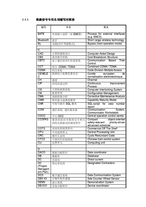
1.1.1 铁路信号专用名词缩写对照表自动站间闭塞:Automatic inter-sation block铁路信号:Railway singal无绝缘轨道电路:Jointless track circuit综合防雷:Synthesized lightning protection铁路车站电码化技术条件:railway station coding of continuous truck circuits specificationZPW-2000A无绝缘移频轨道电路:ZPW-2000A jointless audio frequency-shift modulate truck circuit电码化:Coding正线电码化:main line coding防雷:lightning protection屏蔽:shielding转辙机:Switching machine机车信号:Cab signal补偿电容:Compensative Capacitor轨道电路:truck circuit电磁兼容:Electromagnetic compatibility (EMC)闭环电码化轨道电路:Closed loop coded track circuit站内电码化系统:Coded System Within Station双机热备:Dual machine hot standby微机监测:Computerized monitoring侧线:side line正线:main line计轴:Axle counter铁路运行:railway transport计算机联锁系统:Computer Interlocking system (CIS)管理信息系统:Manage Information system (MIS)单线:single line信号机:Signal自动控制:Automatic control高速铁路:High-speed line铁路行车调度信号系统:Railway Traffic Control Information system客运专线:passenger special line传输协议:Transport Protocols列车自动保护:Automatic train protection (AIP)应答器:balise固态继电器:Solid State Relay(SSR)发送器:transmitter接收器:receiver低道床电阻:Low ballast bed resistance安全防护:Safety Protection道口信号:Level crossing signal。
HEIDENHANN Connected Machining 产品说明说明书

Connected Machining Individual Solutions for Digital Order Management in Production09/20172The center of every metalworking manu-facturing company is the workshop. Highly qualifi ed specialists work here on modern milling machines and lathes. This is where the workpieces are produced. This is where experience and expertise determine the quality of the products and the effi ciency of the manufacturing process.The discussion about digitization raises big expectations in many manufacturing companies, but it also presents new challenges. The main question is how digital networking and software solutions can be used to analyze one’s own manu-facturing processes, improve internal processes, and tailor the use of external services, such as cloud solutions.C onnected Machining With its Connected Machining package of functions, HEIDENHAN offers solutions for individual networking of production pro-cesses. These solutions place the user at the center of digital order management through the control of his milling or turning machine. The HEIDENHAIN control is net-worked with all production-related areas within the company on a very individual ba-sis tailored to the existing structures and open for future developments.Y ou are supported in your work through simple data usage, time-saving workfl ows and transparent processes in all company areas. This applies of course in the work-shop, but also during design and produc-tion planning, as well as in management, logistics, servicing, etc. The production-related strengths of modern machines and plants are thus supplemented through a uniform digital job management with Connected Machining.Contents34Networked manufacturing –Making know-how useable and protecting it at the same timeCreativity and innovative power drive the important and unique features that make a production company successful. This is driven by innovative and motivatedemployees who place their expertise at the service of the company. T o use this private, highly sensitive know-how in a targeted manner and protect it at the same time places manufacturing companies before crucial challenges.Connected Machining deliberately makes control of the machine in the workshop the focal point of digital order management. HEIDENHAIN is therefore consistently pursuing what it already began with the TNC control and the Klartext programming format as a dialog-oriented programming language in the mid-1970s: providing the specialist in the workshop with powerful, intuitive solutions for the production of high-quality workpieces.The realization of uniform digital order management with Connected Machining through HEIDENHAIN control leaves the necessary leeway for individual design and connection of the network. Connected Machining offers the necessary openness with its comprehensive capabilities and digital interfaces.Even a simple TNC control systemintegrated into the company network via Ethernet offers with its standard functions a wide range of options for receiving and using digital job data directly on the control:•PDF viewer, e.g. for displaying of fi xture diagrams and design drawings •DXF viewer, e.g. for displaying 3-D models•Image display, e.g. for displaying fi xture situations and manufacturing notes •Web browser for accessing web-based applications, such as ERP and MESclients, e-mail clients, and HTML5 clientsBeyond this, the following solutions and options are offered:•The StateMonitor software creates transparent processes through data acquisition and data analysis.•The Remote Desktop Manager(option 133) allows access to PCs and the installed software right at the control •The HEIDENHAIN DNC interface (option 18) connects the control to enterprise-resource planning and production-activity control systems •The Extended Workspace display provides clear representation and processing of the job data on the machineThe employees in the company keep the digital threads in their hands to be able to use the internal know-how individually—whether on the machine tool in the workshop, in the design stage or in production planning.In production, on the machine, all the information is quickly and immediately available that is necessary for continuous high-quality production planning and enables a fl exible order management from a batch size of one.5Order data and due datesImportant information such as order number, desired delivery date, order volume and required materials can be viewed directly with the integrated web browser of the HEIDENHAIN controls and corresponding web applications or with the help of the Remote Desktop Manager directly on the order server. Preparations on the machine can be quick, paperless and free of routing slips.Preparation of productionThe necessary production data such as NC programs, fi xture and test plans, or 2-D and 3-D data can be transmitted digitally to the control via the DNC interface. HEIDENHAIN controls offer even as standard features an image display as well as PDF and DXF viewers to view these data.Communication interfaces allow toolmanagement systems to directly compare data with the controller. It is also possible to send confi rmation of fi nished orders via the control automatically, either via DNC interface or the StateMonitor software. With appropriate MES and ERP systems, the user can also enter them manually through a web browser.–Powerful solutions on the controlData access during production Fast and fl exible reaction to changes requires clearly laid out, always available data. If, for example, machining strategies are wrong, or if the part program has to be examined in more detail and even edited, the NC data generation of the CAM system quickly comes into play.The Remote Desktop Manager allows access to the data of the CAM system from the PLC during NC machining. With its help, the user is able to call up the fi rst information on the machine and conduct examinations.Overview and documentation during productionWith the expanded display of Extended Workspace, the user has additionalworkspace available on which he displays the CAM system as needed. He has the NC program running in parallel on the control screen.In addition, Extended Workspace also makes it possible to display other applica-tions such as process monitoring, monitor-ing and status information. Whether a workspace camera or display of multi-ma-chine status at the push of a button—a clear status overview helps the user to quickly locate and correct problems on a machine such as a tool failure.StateMonitor can also send targeted status messages on events via e-mail. The events and recipients of the status e-mails are freely confi gurable.6Networked manufacturing –Support in the offi ceSimple production planningConnected Machining also supports production planning. If all production-relevant data are known and prepared for an order, the order data can be transmitted to the machine tool via a DNC interface or can be provided on a server for retrieval. The user receives information digitally via e-mail or through a web application. He can either use an e-mail client on an IPC or the web browser of the HEIDENHAIN control via the Remote Desktop Manager. This reduces paperwork and eliminates superfl uous communications.The constantly available information about current production orders is also a valuable tool for production planning. This informa-tion can be displayed and tracked quickly and easily via StateMonitor's machine data acquisition. But StateMonitor does not simply display machine data. The software also allows its evaluation and comments on events. This provides important data for optimizing the organizational sequence of production.Data exchange for continuous horizontal integrationIn an automated production setup,Connected Machining can implement a targeted data exchange over the DNC interface. Handover units or tool andworkpiece handling systems for example, then always provide the right information at the right time in order to make the fl ow of automation trouble-free. The communica-tion is over Ethernet interface, supported by commonly available fi eldbus systems.Coordinated order and production planningA good overview of the current production process facilitates further planning, e.g. for the procurement of tools, the preparation of follow-up orders or the logistics around the fi nished parts. In particular the manag-ers of manufacturing and production re-quire simple and easily accessible informa-tion as provided by StateMonitor. These data ensure plannable production that is successful in the long term and offers the necessary security for investments.Systematically reduce unplanned shutdownsStateMonitor provides confi gurable fault messages and, if desired, documents machine messages in the log that are then available as machine history. Their evaluation can show creeping wear and tear or possible disturbances, so that early preventive measures can be planned and production losses can be avoided.For maintenance and service, the DNC in-terface also supports planning in advance. Third party providers, for example, can pick up the necessary machine data via HEIDEN-HAIN DNC from the control for evaluation and use it to assess the maintenance situa-tion or to correct problems.Sound investment planning Machine utilization and the effi ciency of the machines are a key aspect in investment planning. They provide valuable information on whether old machines should be mod-ernized, machinery should be expanded or further automation should be considered. The StateMonitor helps you with these decisions and ensures transparency.7StateMonitor – Acquiring and evaluating machine dataStateMonitor records the states of the machines in production and visualizesthem. By evaluating important data such as current machine status, machine messag-es, override positions and utilization history, StateMonitor provides in-depth information on the machine's degree of utilization. StateMonitor also uses the collected data to show existing optimization possibilities. The operator can enter comments on machine downtimes and set-up times in order to uncover machine-specifi c as well as organizational potential for optimization. Using the messenger function, StateMonitor notifi es the responsible person by e-mail of specifi c events such as program end, machine standstill, or service warnings based on individually combinable machine signals and statuses.State Monitor is installed on a server in the company network and collects machine states of HEIDENHAIN controls via the HEIDENHAIN DNC interface. The software runs in the local network as a client-server application and has a web-based user interface. This allows StateMonitor to be displayed and operated via any device (TNC controls, PCs, mobile devices) that has a web browser and has access to the respective server. No further software or app has to be installed on the respective display and control units. It is suffi cient to enter or store the respective web address. The user interface of StateMonitor adapts to the respective screen resolution and can be operated by mouse as well as by a touchscreen.StateMonitor captures and visualizes the following information of the networked machines:• Operating modes• Override positions (spindle, rapid traverse, feed rate)• Program status and program name, if appropriate also subprograms • Program run time• SIK number and software number • Machine messages StateMonitor is installed on a server or PC with Windows operating system, the so-called host. The hardware prerequisites depend on the number of machines to be connected. The HEIDENHAIN controls to be connected must be accessible from the server through the IP address or DHCP name. Also, HEIDENHAIN control must have HEIDENHAIN DNC (option 18).8k+CAMERPPPSCADTNC 640IPC R emote Desktop Manager– Display and remote control of external computer unitsIn daily operations it can often be neces-sary to make entries in planning and con-trol systems or perform diagnostics usingWindows-based software. The RemoteDesktop Manager option provides theuser with the opportunity to operate one ormore Windows PCs directly from the TNC.It offers complete integration of WindowsPC operation in the user interface of theTNC control’s screen.With a simple keystroke on the machineoperating panel you can switch betweenthe control screen and the screen of a sep-arate Windows PC in your local network.And it makes no difference whether theWindows computer operates as an indus-trial PC (e.g. IPC 6641) in the machine’scontrol cabinet, or as a server in the localnetwork.Possible applications include the centralmanagement of job orders or tools and NCprograms, all the way to remote operationof CAD/CAM systems from the machine.In this way, the machine tool operatingpanel becomes a fl exible and effi cientworkplace for the steps in the CAD/CAM/CNC process chain, including decentralizedorder processing.The Remote Desktop Manager can be setup through the control’s operating system.Remote Desktop Manager Option 133ID 894423-01TNC 640 HSCITNC 620 HSCITNC 320iTNC 530 HSCIiTNC 530As of NC SW 34059x-01As of NC SW 81760x-01–As of NC SW 60642x-02–Installation by IT specialistsFor more information see the T echnical ManualsConnected Machining permits uniformlydigital order management in networkedmanufacturing Y ou also profi t from:• Easy data usage• Time-saving procedures• T ransparent processesDocumentsE-mail9Paperless order management requires the seamless exchange of data about all process steps in the production process. The HEIDENHAIN DNC option enables a Windows application to access data of the TNC, and to edit the data if required. Possible fi elds of application include, for example:• Software solutions controlling the manufacturing process – M achine and operating-data acquisition systems (MDA/PDA) – C onnection to higher -level ERP/MES systems – P lanning of preventive maintenance based on the actual condition of the machine• Standard or customer -specifi c PC software – I ncrease in process reliability and system availability – E rror reporting systems that, for example, send the customer amessage to his smartphone reporting problems with the currently running machining process – O verview plans that provideinformation about the current condition of all machines used in production – C reation of a database for comprehensive data mining RemoT ools SDK development package T o enable you to use the HEIDENHAIN DNC software interface, HEIDENHAIN offers the RemoT ools SDK software devel-opment package. RemoT ools SDK provides a Microsoft COM component for the devel-opment environments on Windows operat-ing systems in order to make communi-cation with the HEIDENHAIN control possible. During the installation of Remo-T ools SDK the COM component is regis-tered in the Windows operating system.HEIDENHAIN DNC– Communication via COM components10Extended Workspace – Expanded displayExtended Workspace makes it possible to work in parallel on the machine and job management directly at the machine and control. A second screen with an integrat-ed computer is simply connected to the controller via Ethernet and confi gured as an additional screen in the TNC operating system. This enables the user to work ef-fectively and knowledgeably with additional applications on the second screen without losing his grasp on the center of his work on the control screen.The applications for the additional screen workspace are multiple:• Parallel work during NC program run on: –Order management–CAD/CAM programming (e.g. via Remote Desktop Manager) –Documentation –Machine-specifi c applications(e.g. the use of maintenance software)• Monitoring the working space• Operating two or more machines by one machine operator, display of StateMonitor's machine overview on the second screenExtended Workspace can be confi gured individually for the desired applications. The computer integrated in the second screen has a powerful processor and thus relieves the main computer of the controller. The applications run natively on the computer of Extended Workspace which, however, receives all necessary data from the TNC controller and can also be used for display processes (e.g. PDF and DXF viewer, web browser and image display) during concurrent processes.11Connected Machining– OverviewY ou can fi nd more information in the brochure titled Options and Accessories.HEIDENHAIN worldwide Mastering nano meter accuracy1225632-20 · 3 · 09/2017 · H · Printed in Germany DR. JOHANNES HEIDENHAIN GmbH Dr.-Johannes-Heidenhain-Straße 583301 Traunreut, Germany +49 8669 31-0 +49 8669 32-5061******************。
XMC4500自动化输入输出芯片模块说明书
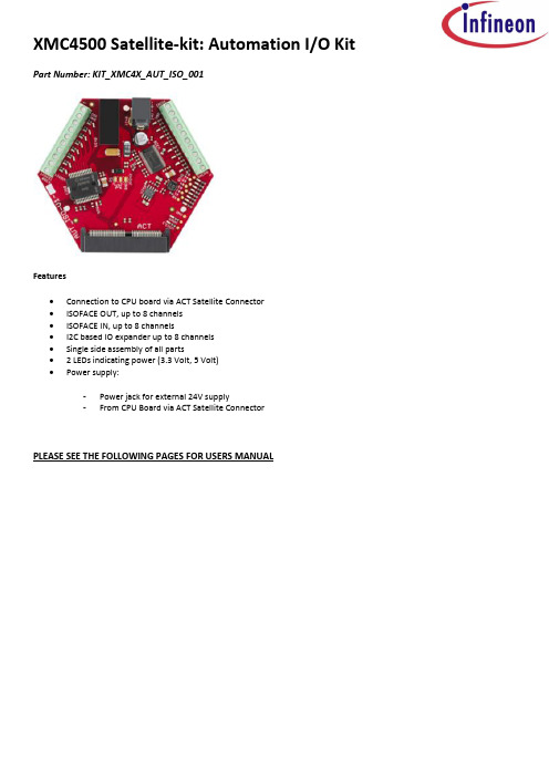
XMC4500 Satellite-kit: Automation I/O Kit Part Number: KIT_XMC4X_AUT_ISO_001Features∙Connection to CPU board via ACT Satellite Connector∙ISOFACE OUT, up to 8 channels∙ISOFACE IN, up to 8 channels∙I2C based IO expander up to 8 channels∙Single side assembly of all parts∙ 2 LEDs indicating power (3.3 Volt, 5 Volt)∙Power supply:-Power jack for external 24V supply-From CPU Board via ACT Satellite ConnectorPLEASE SEE THE FOLLOWING PAGES FOR USERS MANUALHexagon Application Kit For XMC4000 FamilyAUT_ISO-V1Automation I/O CardBoard User's Manual Revision 1.0, 2012-02-28Edition 2012-02-28Published byInfineon Technologies AG81726 Munich, Germany© 2012 Infineon Technologies AGAll Rights Reserved.Legal DisclaimerThe information given in this document shall in no event be regarded as a guarantee of conditions or characteristics. With respect to any examples or hints given herein, any typical values stated herein and/or any information regarding the application of the device, Infineon Technologies hereby disclaims any and all warranties and liabilities of any kind, including without limitation, warranties of non-infringement of intellectual property rights of any third party.InformationFor further information on technology, delivery terms and conditions and prices, please contact the nearest Infineon Technologies Office ().WarningsDue to technical requirements, components may contain dangerous substances. For information on the types in question, please contact the nearest Infineon Technologies Office.Infineon Technologies components may be used in life-support devices or systems only with the express written approval of Infineon Technologies, if a failure of such components can reasonably be expected to cause the failure of that life-support device or system or to affect the safety or effectiveness of that device or system. Life support devices or systems are intended to be implanted in the human body or to support and/or maintain and sustain and/or protect human life. If they fail, it is reasonable to assume that the health of the user or otherTrademarks of Infineon Technologies AGAURIX™, C166™, CanPAK™, CIPOS™, CIPURSE™, EconoPACK™, CoolMOS™, CoolSET™, CORECONTROL™, CROSSAVE™, DAVE™, EasyPIM™, EconoBRIDGE™, EconoDUAL™, EconoPIM™, EiceDRIVER™, eupec™, FCOS™, HITFET™, HybridPACK™, I²RF™, ISOFACE™, IsoPACK™, MIPAQ™, ModSTACK™,my-d™, NovalithIC™, OptiMOS™, ORIGA™, PRIMARION™, PrimePACK™, PrimeSTACK™, PRO-SIL™, PROFET™, RASIC™, ReverSave™, SatRIC™, SIEGET™, SINDRION™, SIPMOS™, SmartLEWIS™, SOLID FLASH™, TEMPFET™, thinQ!™, TRENCHSTOP™, TriCore™.Other TrademarksAdvance Design System™ (ADS) of Agilent Technologies, AMBA™, ARM™, MULTI-ICE™, KEIL™, PRIMECELL™, REALVIEW™, THUMB™, µVision™ of ARM Limited, UK. AUTOSAR™ is licensed by AUTOSAR development partnership. Bluetooth™ of Bluetooth SIG Inc. CAT-iq™ of DECT Foru m. COLOSSUS™, FirstGPS™ of Trimble Navigation Ltd. EMV™ of EMVCo, LLC (Visa Holdings Inc.). EPCOS™ of Epcos AG. FLEXGO™ of Microsoft Corporation. FlexRay™ is licensed by FlexRay Consortium. HYPERTERMINAL™ of Hilgraeve Incorporated. IEC™ of Commission Electrotechnique Internationale. IrDA™ of Infrared Data Association Corporation. ISO™ of INTERNATIONAL ORGANIZATION FOR STANDARDIZATION. MATLAB™ of MathWorks, Inc. MAXIM™ of Maxim Integrated Products, Inc. MICROTEC™, NUCLEUS™ of Mentor Graphics Corporation. Mifare™ of NXP. MIPI™ of MIPI Alliance, Inc. MIPS™ of MIPS Technologies, Inc., USA. muRata™ of MURATA MANUFACTURING CO., MICROWAVE OFFICE™ (MWO) of Applied Wave Research Inc., OmniVision™ of OmniVision Technologies, Inc. Openwave™ Openwave Systems Inc. RED HAT™ Red Hat, Inc. RFMD™ RF Micro Devices, Inc. SIRIUS™ of Sirius Satellite Radio Inc. SOLARIS™ of Sun Microsystems, Inc. SPANSION™ of Spansion LLC Ltd. Symbian™ of Symbian Software Limited. TAIYO YUDEN™ of Taiyo Yuden Co. TEAKLITE™ of CEVA, Inc. TEKTRONIX™ of Tektronix Inc. TOKO™ of TOKO KABUSHIKI KAISHA TA. UNIX™ of X/Open Company Limited. VERILOG™, PALLADIUM™ of Cadence Design Systems, Inc. VLYNQ™ of Texas Instruments Incorporated. VXWORKS™, WIND RIVER™ of WIND RIVER SYSTEMS, INC. ZETEX™ of Diodes Zetex Limited.Last Trademarks Update 2011-02-24Table of ContentsTable of Contents1Overview (7)1.1Key Features (7)1.2Block Diagram (8)2Hardware Description (8)2.1ISOFACE OUT (9)2.2ISOFACE IN (9)2.3IO Expander (10)2.4Power (11)2.5Satellite Connector (12)3Production Data (13)3.1Schematics (13)3.2Layout and Geometry (16)3.3Bill of Material (17)List of FiguresFigure 1Automation I/O Card (AUT_ISO-V1) (8)Figure 2Automation I/O Card Interfaces (8)Figure 3Power Circuit (11)Figure 4ACT Satellite Connector (12)Figure 5Satellite Connector Type ACT (12)Figure 6Satellite Connector, IO Expander, Power (14)Figure 7ISOFACE (15)Figure 8Automation I/O Card Layout (16)List of TablesTable 1ISOFACE OUT Connector Pinout (9)Table 2ISOFACE OUT signal connection to the Satellite Connector (9)Table 3ISOFACE IN Connector Pinout (9)Table 4ISOFACE IN signal connection to the Satellite Connector (10)Table 5GPIO channel LED/SMD pad mapping (10)Table 6IO Expander I2C signal connection to the Satellite Connector (10)Table 7Power LED’s (11)Table 8PowerScale Jumper (11)Table 9Automation I/O Card BOM (17)OverviewIntroductionThis document describes the features and hardware details of the Automation I/O Card (AUT_ISO-V1) designed to work with Infineon’s XMC4500 CPU board. This board is part of Infineon’s Hexagon Application Kits.1 OverviewThe AUT_ISO-V1 board is an application expansion satellite card of the Hexagon Application Kits. The satellite card along with a CPU board (e.g. CPU_45A-V2 board) demonstrates ISOFACE capabilities together with XMC4500. The focus is safe operation under evaluation conditions. The satellite card is not cost optimized and cannot be seen as reference design.1.1 Key FeaturesThe AUT_ISO-V1 satellite card is equipped with following featuresConnection to CPU board (e.g. CPU_45A-V2) via satellite connector ACTISOFACE OUT, up to 8 channelsISOFACE IN, up to 8 channelsI2C based IO expander up to 8 channelsPower supplyo Powerjack for external 24 V supplyo From CPU board via ACT satellite connector1.2Block DiagramFigure 1 shows the block diagram of the AUT_ISO-V1 satellite card. There are following building blocks:Figure 1Automation I/O Card (AUT_ISO-V1)2 Hardware DescriptionThe following sections give a detailed description of the hardware and how it can be used.Figure 2 Automation I/O Card InterfacesISOFACE OUT (ISO1H812G)ISOFACE IN (ISO1I811T)Power 3.3 V (IFX1763SJV33)ISOFACE IN ConnectorACT Satellite ConnectorPower Jack24 V2.1 ISOFACE OUTISOFACE output device used in AUT_ISO-V1 satellite card is ISO1H812G. It is supplied by VDD3.3 on the CPU side and VDD24 for the ISOFACE OUT side. VDD24 and GNDISO can to be connected either by X300 or by X240(24 V external power jack). This is the same net that supplies the DC/DC converter. VDD24 is +24 Vdc (referred to GNDISO)Table 1 below gives the signal details of ISOFACE OUT connector.Table 12 below gives the details of SPI signal connection to the satellite connector.2.2 ISOFACE INISOFACE input device used in AUT_ISO-V1 satellite card is ISO1I811T. It is supplied by 3.3 V on the CPU side and VBB (24V) for the ISOFACE IN side. VBB and GNDBB need a separate connection to 24 V external power source through connector X320.Resistor R337 is used on board for setting input type to IEC61131-2 Type 1.Resistors R326 and R327 sets the frequency of ISOFACE IN to 100 kHz (default).Table 3 gives the details of ISOFACE IN connector pin mapping.Table 3 ISOFACE IN Connector PinoutISOFACE IN shares the same SPI lines with ISOFACE OUT except the chip select as shown in Table 4.2.3 IO ExpanderThe AUT_ISO-V1 satellite card supports GPIO expansion though I2C IO-Expander on board (U230). The I2C Address for IO expander device is 0x1001000X. The satellite card supports 8 such GPIO’s. All t he GPIO’s are connected to LEDs (V230-V237) and SMD-Pads (TP230 – TP237). The Table 5 gives the GPIO channel and corresponding LED/PAD mapping.Table 6 shows the connection of the IO Expander device to the ACT satellite connector.2.4 PowerThe AUT_ISO-V1 satellite card can be supplied by an external power supply (24 V / 1 A) to be connected to the power jack X240 or by a 5 V supply via the 80-pin ACT satellite connector. An external power supply is necessary only in case the current coming via the ACT satellite connector is not sufficient.A DC-DC converter on board (U240) steps down the input voltage from the power jack X240 to 5 V (VDD5). The input voltage can be in the range from 12 V to 24 V. An on board linear voltage regulator is generating a 3.3 V (VDD3.3) power supply out of the VDD5.Figure 3 Power CircuitA Diode V242 protects the reverse flow of current to an external source. Therefore a simultaneous power supply of the satellite boards via both the power jack and the satellite connector with not harm.LED V210 indicates the presence of 5 V power and LED V211 indicates the presence of 3.3 V power.Table 7 Power LED’sThe AUT_ISO-V1 satellite card supports a PowerScale probe for power measurement purpose.Table 8 PowerScale Jumper2.5 Satellite ConnectorThe satellite connector of the AUT_ISO-V1 satellite card interfaces it’s the signals to a CPU board e.g. CPU_45A-V2. Take care to connect the ACT satellite card always to the corresponding ACT satellite connector of the CPU board only.Figure 4 ACT Satellite ConnectorThe signal mapping of the ACT satellite connector and correponding CPU function are provided in figure 6Figure 5 Satellite Connector Type ACT3 Production Data3.1 SchematicsThis chapter contains the schematics for the Automation I/O Card:Satellite Connector, IO Expander, PowerISOFACEFigure 6 Satellite Connector, IO Expander, PowerFigure 7 ISOFACE3.2 Layout and GeometryFigure 8 Automation I/O Card Layout3.3 Bill of MaterialTable 9 Automation I/O Card BOMTable 9 Automation I/O Card BOMw w w.i n f i n e o n.c o m。
SPARC V8处理器基于PC 104嵌入式计算机模块设计说明书
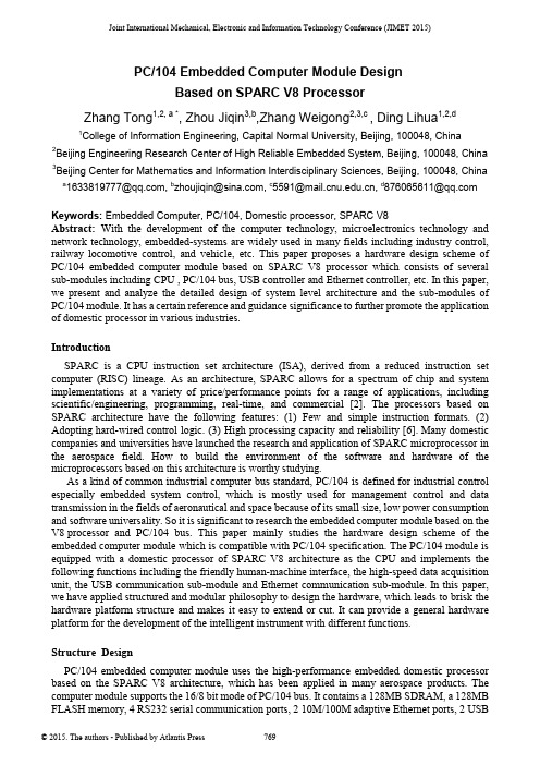
Joint International Mechanical, Electronic and Information Technology Conference (JIMET 2015)PC/104 Embedded Computer Module DesignBased on SPARC V8 ProcessorZhang Tong1,2, a *, Zhou Jiqin3,b,Zhang Weigong2,3,c , Ding Lihua1,2,d1College of Information Engineering, Capital Normal University, Beijing, 100048, China2Beijing Engineering Research Center of High Reliable Embedded System, Beijing, 100048, China 3Beijing Center for Mathematics and Information Interdisciplinary Sciences, Beijing, 100048, China a*****************,b******************,c*************,d****************Keywords: Embedded Computer, PC/104, Domestic processor, SPARC V8Abstract: With the development of the computer technology, microelectronics technology and network technology, embedded-systems are widely used in many fields including industry control, railway locomotive control, and vehicle, etc. This paper proposes a hardware design scheme of PC/104 embedded computer module based on SPARC V8 processor which consists of several sub-modules including CPU , PC/104 bus, USB controller and Ethernet controller, etc. In this paper, we present and analyze the detailed design of system level architecture and the sub-modules of PC/104 module. It has a certain reference and guidance significance to further promote the application of domestic processor in various industries.IntroductionSPARC is a CPU instruction set architecture (ISA), derived from a reduced instruction set computer (RISC) lineage. As an architecture, SPARC allows for a spectrum of chip and system implementations at a variety of price/performance points for a range of applications, including scientific/engineering, programming, real-time, and commercial [2]. The processors based on SPARC architecture have the following features: (1) Few and simple instruction formats. (2) Adopting hard-wired control logic. (3) High processing capacity and reliability [6]. Many domestic companies and universities have launched the research and application of SPARC microprocessor in the aerospace field. How to build the environment of the software and hardware of the microprocessors based on this architecture is worthy studying.As a kind of common industrial computer bus standard, PC/104 is defined for industrial control especially embedded system control, which is mostly used for management control and data transmission in the fields of aeronautical and space because of its small size, low power consumption and software universality. So it is significant to research the embedded computer module based on the V8 processor and PC/104 bus. This paper mainly studies the hardware design scheme of the embedded computer module which is compatible with PC/104 specification. The PC/104 module is equipped with a domestic processor of SPARC V8 architecture as the CPU and implements the following functions including the friendly human-machine interface, the high-speed data acquisition unit, the USB communication sub-module and Ethernet communication sub-module. In this paper, we have applied structured and modular philosophy to design the hardware, which leads to brisk the hardware platform structure and makes it easy to extend or cut. It can provide a general hardware platform for the development of the intelligent instrument with different functions.Structure DesignPC/104 embedded computer module uses the high-performance embedded domestic processor based on the SPARC V8 architecture, which has been applied in many aerospace products. The computer module supports the 16/8 bit mode of PC/104 bus. It contains a 128MB SDRAM, a 128MB FLASH memory, 4 RS232 serial communication ports, 2 10M/100M adaptive Ethernet ports, 2 USBports and a VGA display port with 1600*1200 display resolution. In this PC/104 module, we have configured VxWorks operating system including BSP, USB keyboard mouse driver, Ethernet driver, UART driver, TFFS file system and other software driver [1]. Drivers are designed for the corresponding hardware devices, such as USB, Ethernet, UART and display control circuit to manage the underlying hardware, which can provide a standardized and hardware-independent interface to the high-level application software. Fig. 1 shows the main block diagram of PC/104 embedded computer module.Fig. 1 The main block diagram of PC/104 embedded computer moduleHardware Module Design Based on Domestic ProcessorCPU Sub-module A 32-bit microprocessor based on SPARC V8 architecture with the high degree of integration and high performance is adopted in this design. Fig. 2 shows the internal structure of the processor. From Fig. 2, we can see the processor chip contains an on-chip integer processing unit IU, a floating-point unit (FPU), independent data caches and instruction caches, 5 stage pipeline, hardware multiplier and divider and so on. Moreover, interrupt controller, hardware debug unit with tracking buffer storage (DSU), two common timer (timer0, timer1), serial interface, PCI interface, watchdog timer and memory controller supporting PROM, SRAM, SDRAM and I/O space accessing and so on are integrated in this processor chip[4].Fig. 2 The structure diagram of SPARC V8 CPUPC/104 Bus Sub-module The electrical logic of PC/104 specification uses ISA bus specification. It defines two types ofaddress space including I/O space and memory space, supporting 8-bit and 16-bit data accessing. The hardware of PC/104 can configure 11 interrupt sources and provide 7 DMA Channels. Due to the characteristics of V8 processor chip, in the designing of PC/104 module, we use dual space mapping mode to support the 8/16 read-write functions of PC/104 bus. The I/O space of V8 processor has the following two regions:(1) One region is used to deal with the 16-bit read-write functions of PC/104 bus, which can be divided into two subspaces, namely I/O space and memory space. The PC/104 bus accessing operations to this space are all considered to be 16-bit read-write mode. In this region, the MEMCS16# and IOCS16# signals are all ignored (assuming the device accessed is 16 bits).(2) Another region is specifically designed for 8-bit read-write functions of PC/104 bus, which can also be divided into two subspaces, namely IO space and storage space. The PC/104 bus accessing operations to this space are considered to be 8-bit read-write mode. The accessed device is served as an 8-bit device or a 16-bit device by the MEMCS16# and IOCS16# signal and the PC/104 data bus is mapped into the corresponding space of the processor.In order to improve the efficiency of bus accessing and the controlling flexibility, we implement the bus sequential control logic circuits on a FPGA chip. Through this designing method, the PC/104 bus sequence can be set flexibly by configuring the software, for example, the length (T1) of the address latch signal (BALE) or the default length (T2) of the bus access cycle can be changed by modifying the control register. The PC/104 bus sequence waveforms are shown in Fig. 3. In this figure, the term T4 is the time gap between the BALE falling edge and read-write signal falling edge, which has a minimum value of zero.As shown in Fig. 3, the length of T1 can be set by the BALEW domain of PC/104 bus sequence control register (ISATIMING). The length of T4 is 0~10ns. The length of T3 is T2-T1-T3. The default value of T2 is set by the ISAW domain of ISATIMING register.Fig. 3 PC/104 bus waveform DiagramUSB Sub-module In this paper, we use CH374U (produced by Nanjing QinHeng Electronics Co.,Ltd.) as the USB controller of PC/104 embedded computer module and implement two USB1.0 ports (usb0, usb1), which can connect keyboard, mouse, or the other USB external devices. The interface of USB adopts PulseGuard ESD protection circuit to implement the over-voltage protection. CH374U supports both USB-HOST and USB-DEVICE mode with root hub of 3 ports. It has multiple transmission method, including low speed and full speed control transmission, bulk transmission, interrupt transmission, and synchronous transmission. CH374U uses four I/O registers to interact with the CPU and can generate an interrupt request to CPU. The four registers are all adopted 16-bit accessing mode, but only low 8 bits are effective. High 8 bits are read with constant zero and writing in is arbitrary. The hardware block diagram of USB is shown in Fig. 4.Fig. 4 USB signal connection diagramEthernet Sub-module The two-way 10M/100M adaptive Ethernet interface (LAN1, LAN2) is implemented with the module using DM9000CIEP owned by Davicom Semiconductor, Inc. In order to improve the reliability of the internal work of the PC/104 embedded computer module, the double isolation interface scheme is adopted in the Ethernet interface, namely the input and output signals separated by the transformer. Two way Ethernet interfaces can work independently and also can be redundant backup for each other used under the driver management [5]. The hardware block diagram is shown in Fig. 5.ADRESSBALER/WIOCHRDYRead DataWrite DataFig. 5 Ethernet signal connection DiagramTest resultsThe cast plate is made according to the above design and the module real figure is shown in Fig. 6. The PCB boards are put to the test and the tests are mainly about the validity of the various functions modules of the PC/104 embedded computer module. The tests are mainly as follows:Fig. 6 Module physical Diagram(1) CPU functional testing, the main function is to test the cache, perform the same cycle, it is 19us to open the cache code, 195us to close the cache code time.(2) In order to test the PC/104 module more fully, we design a motherboard with a CPLD chip which implements several registers including ISA bus interrupt request control register, accessing latency control register, clock-timing registers.The V8 PC/104 computer module can access these functional registers by internal ISA bus in order to control the CPLD to generate the bus interrupts or modify the bus latency. Using these control method, we can implement the test of PC/104 module.The generation and clear of the PC/104 bus interrupt signal is controlled by the interrupt request register and the interrupt enable register, which is how the bus interrupt signal is tested.The bus access cycle controller is mainly to test the validity of the bus access after inserting the different length of wait states the maximum of which is 256us. These waiting for the cycle controllers is only effective for testing the functional registers (IO address 0000 ~ 00FFH). The signal IOCHRDY is in the state of high resistance and the default cycle is adopted while the registers are accessed by other ISA address.The timer is set with a kind of bus clock when the clock timing is tested. And firstly the 33MHz (CPLD operating clock), 14.318MHz (bus BCLK clock), 14.318MHz (bus OSC clock) are respectively divided into 1MHz by an internal frequency divider, and then the signal is stipulated-timing-controlled by a set of registers. When it comes to overflowing in the timer, the interrupt request is applied to the ISA bus by the interrupt request signal (IRQ12, 14 or 15). And the timer can be tested by software reading the timer count.(3) Ethernet communication test: Two way Ethernet are connected to the test monitoring computer with the router. Ethernet transferring the data is normal and the average transfer rate is about 1Mbps, and the error rate is zero, and the packet loss rate is zero.(4) In the operating system, SDRAM memory which is not occupied by the operating system is accessing tested. In order to accurately test the validity of the data bus, writing-in data must have wide adaptability, including 0x55555555、0xaaaaaaaa、0x1、0x2、0x4、0x8、0x10、……、0x80000000. The data in two formats is mainly tested for reading the preliminarily stored data in the FLASH memory. One is the binary data stored in the space that is not changed into the file system, the other is a file stored in the file system, and the test results are correct. Display images and memory access test: After receiving the test command, the specific graphics display functions are called so that the specific graphics can be displayed on the display and the read and write accessing to the display buffer memory is normal. In the RS232 communication test, four RS232 interfaces of the V8 PC/104 computer module are two-two interconnected to send and receive data, and serial data transmission is normal, and the average Baud rate is about 90kbps, and the error rate is zero.ConclusionsThe embedded system has been widely used in the field of industrial control, such as industrial process control, intelligent instrument, and numerical control system. Especially with the network technology and communication technology rapidly booming, the networked site of the industrial control has become a trend. In this paper, after studying the development situation of the embedded system at home and abroad, the relatively complete solution to the embedded application system is designed with a high-performance domestic embedded processor based on SPARC V8 architecture. And the 128MB bytes of FLASH that is used to store all the program codes and parameters is extended in this system and the 128MB bytes of SDRAM that is used to store running programs and data is extended in this system and PC/104 bus is extended in this system to improve the efficiency of bus access and control flexibility. Moreover, USB, Ethernet communication interface and etc. are designed in this system. The testing results indicate that the function indexes and performance indexes meet the requirements. This module is featured in a small size, powerful functions, low power consumption, high reliability, good compatibility and low cost [3], which means it can be applied in different fields of the industrial occasions.AcknowledgmentsThis work was supported in part by the National Natural Science Foundation of China (No.61170009, No.61472260, No.61402302); Beijing Natural Science Foundation of China (No.4132016, No.4143060); the Project of Construction of Innovative Teams and Teacher Career Development for Universities and Colleges Under Beijing Municipality(No.IDHT20150507); the Scientific Research Base Development Program of the Beijing Municipal Commission of Education. References[1] Zhang Lihong, Ren Yu, Chen Jianzheng, Data Acquisition System Based On PC/104, Engineering and Test,2009,3[2] The SPARV Architecture Manual, Version 8[3] Cao Zhijin, Hou Xia, Wu Qiuping, Master-slave data acquisition systems and applications based on PC/104,Electrical Measurement and Instrumentation, 2003,4[4] Yu Dan, Zhang Zhuancheng, Feng Lijie, Lai Yuqiang, LEON2 processor-based SoC designs based on LEON2 processor, Modern electronic technology, 2005[5] Chen Yi, Wang Lei, Zhou guojia, Li Zhe, Radiation Monitoring Network and Ethernet Interface Based On CAN bus, Nuclear Electronics and Detection Technology,2011[6] Zhu Xiaoyan, Zhang Weigong, Wang Jianfeng, Duan Qingya, and Liu Shurong, “The design of high reliable serial system BUS”. Proceedings of Computer Design and Applications, Qinhuangdao,Hebei, China, 25-27 June 2010; pp.V4-14-V4-17.。
莫萨公司MGate MB3180 MB3280 MB3480系列1、2和4端口标准串行到以太网Mod

MGate MB3180/MB3280/MB3480Series1,2,and4-port standard serial-to-Ethernet Modbus gatewaysFeatures and Benefits•Supports Auto Device Routing for easy configuration•Supports route by TCP port or IP address for flexible deployment•Converts between Modbus TCP and Modbus RTU/ASCII protocols•1Ethernet port and1,2,or4RS-232/422/485ports•16simultaneous TCP masters with up to32simultaneous requests permaster•Easy hardware setup and configurationCertificationsIntroductionThe MB3180,MB3280,and MB3480are standard Modbus gateways that convert between Modbus TCP and Modbus RTU/ASCII protocols.Up to 16simultaneous Modbus TCP masters are supported,with up to31RTU/ASCII slaves per serial port.For RTU/ASCII masters,up to32TCP slaves are supported.Routing through the serial ports can be controlled by IP address,TCP port number,or ID mapping.Serial-port routing by TCP port and IP address allows access for up to4TCP clients/masters(MB3280/MB3480models),while routing by ID mapping allows access for up to16 TCP clients/masters(MB3180/MB3280/MB3480).Standard Modbus Network IntegrationThe three standard MGate™models(MB3180,MB3280,and MB3480)are designed for easy integration of Modbus TCP and RTU/ASCII networks. With these models,Modbus serial slave devices can be seamlessly incorporated into an existing Modbus TCP network,and Modbus TCP slaves can be made accessible to serial masters.The MB3180,MB3280,and MB3480offer features that make network integration easy,customizable, and compatible with almost any Modbus network.High Density,Cost-Effective GatewaysThe MGate™MB3000gateways can effectively connect a high density of Modbus nodes to the same network.The MB3280can manage up to62 serial slave nodes,and the MB3480can manage up to124serial slave nodes.Each RS-232/422/485serial port can be configured individually for Modbus RTU or Modbus ASCII operation and for different baudrates,allowing both types of networks to be integrated with Modbus TCP through one Modbus gateway.Auto-Device Routing for Easy Configuration(patented)Moxa’s Auto-Device Routing function helps eliminate many of the problems and inconveniences encountered by engineers who need to configure large numbers of Modbus devices.A single mouse click is all that’s required to set up a slave ID routing table and configure Modbus gateways to automatically detect Modbus requests from a supervisory control and data acquisition(SCADA)system.By removing the need to manually create the slave ID routing table,the Auto-Device Routing function saves engineers significant time and cost.SpecificationsEthernet Interface10/100BaseT(X)Ports(RJ45connector)Auto MDI/MDI-X connectionMagnetic Isolation Protection 1.5kV(built-in)Ethernet Software FeaturesIndustrial Protocols Modbus TCP Client(Master)Modbus TCP Server(Slave)Configuration Options All models:Web Console(HTTP),Device Search Utility(DSU),MGate Manager,MCCTool,Telnet ConsoleMGate MB3280/MB3480only:Web Console(HTTPS)Management All models:ARP,DHCP Client,DNS,HTTP,SNMPv1/v2c/v3,TCP/IP,Telnet,UDPMGate MB3280/MB3240only:HTTPS,SMTP,SNMP Trap,NTP ClientMIB RFC1213,RFC1317Time Management NTP Client(MGate MB3180Excluded)Security FunctionsAuthentication Local databaseEncryption HTTPSAES-128AES-256SHA-256Security Protocols SNMPv3HTTPS(TLS1.2)(except MGate MB3180)Serial InterfaceNo.of Ports MGate MB3180:1MGate MB3280:2MGate MB3480:4Connector DB9maleSerial Standards RS-232/422/485(software selectable)Baudrate50bps to921.6kbpsData Bits7,8Parity NoneEvenOddSpaceMarkStop Bits1,2Flow Control DTR/DSRRTS Toggle(RS-232only)RTS/CTSRS-485Data Direction Control ADDC(automatic data direction control)Pull High/Low Resistor for RS-4851kilo-ohm,150kilo-ohmsTerminator for RS-485MGate MB3180:NoneMGate MB3280/MB3480:120ohmsSerial SignalsRS-232TxD,RxD,RTS,CTS,DTR,DSR,DCD,GNDRS-422Tx+,Tx-,Rx+,Rx-,GNDRS-485-2w Data+,Data-,GNDRS-485-4w Tx+,Tx-,Rx+,Rx-,GNDSerial Software FeaturesIndustrial Protocols Modbus RTU/ASCII MasterModbus RTU/ASCII SlaveModbus(Transparent)Max.No.of Client Connections16Max.No.of Server Connections32Power ParametersInput Voltage12to48VDCInput Current MGate MB3180:200mA@12VDCMGate MB3280:250mA@12VDCMGate MB3480:365mA@12VDCPower Connector MGate MB3180:Power jackMGate MB3280/MB3480:Power jack and terminal blockPhysical CharacteristicsHousing MetalIP Rating IP301Dimensions(with ears)MGate MB3180:22x75x80mm(0.87x2.95x3.15in)MGate MB3280:22x100x111mm(0.87x3.94x4.37in)MGate MB3480:35.5x102.7x181.3mm(1.40x4.04x7.14in)Dimensions(without ears)MGate MB3180:22x52x80mm(0.87x2.05x3.15in)MGate MB3280:22x77x111mm(0.87x3.03x4.37in)MGate MB3480:35.5x102.7x157.2mm(1.40x4.04x6.19in)Weight MGate MB3180:340g(0.75lb)MGate MB3280:360g(0.79lb)MGate MB3480:740g(1.63lb)Environmental LimitsOperating Temperature MGate MB3180:0to55°C(32to131°F)MGate MB3280:0to60°C(32to140°F)MGate MB3480:0to55°C(32to131°F)Storage Temperature(package included)-40to85°C(-40to185°F)Ambient Relative Humidity5to95%(non-condensing)Standards and CertificationsEMC EN55032/35EMI CISPR32,FCC Part15B Class AEMS IEC61000-4-2ESD:Contact:4kV;Air:8kVIEC61000-4-3RS:80MHz to1GHz:3V/mIEC61000-4-4EFT:Power:1kV;Signal:0.5kVIEC61000-4-5Surge:Power:1kV(MB3180/MB3280)IEC61000-4-5Surge:Power:1kV;Signal:2kV(MB3480)IEC61000-4-6CS:3VIEC61000-4-8PFMFIEC61000-4-11Safety MB3180Models:EN62368-1and UL60950-1MB3280/3480Models:IEC/UL62368-11.For the MGate MB3480,the two screws provided with the wall-mounting kit must be used to fasten the kit to the bottom of the MGate,and the MGate must beproperly attached to the terminal block for power input.MTBFTime MGate MB3180:2,762,384hrsMGate MB3280:749,455hrsMGate MB3480:1,213,993hrsStandards Telcordia SR332WarrantyWarranty Period5yearsDetails See /warrantyPackage ContentsDevice1x MGate MB3180/MB3280/MB3480Series gatewayPower Supply1x power adapter,suitable for your regionDocumentation1x quick installation guide1x warranty cardDimensionsOrdering InformationModel Name No.of Serial Ports MGate MB31801MGate MB32802MGate MB34804 Accessories(sold separately)CablesCBL-F9M9-150DB9female to DB9male serial cable,1.5mCBL-F9M9-20DB9female to DB9male serial cable,20cmConnectorsMini DB9F-to-TB DB9female to terminal block connectorDIN-Rail Mounting KitsDK35A DIN-rail mounting kit,35mmWall-Mounting KitsWK-35-01Wall-mounting kit with2plates(35x44x2.5mm)and6screws©Moxa Inc.All rights reserved.Updated Aug07,2023.This document and any portion thereof may not be reproduced or used in any manner whatsoever without the express written permission of Moxa Inc.Product specifications subject to change without notice.Visit our website for the most up-to-date product information.。
MX行业领先云管理系统说明书

INDUSTRY-LEADING CLOUD MANAGEMENT• Unified firewall, switching, wireless LAN, and mobile device man-agement through an intuitive web-based dashboard• Template based settings scale easily from small deployments to tens of thousands of devices• Role-based administration, configurable email alerts for a variety of BRANCH GATEWAY SERVICES• Built-in DHCP, NAT, QoS, and VLAN management services • Web caching: accelerates frequently accessed content• Load balancing: combines multiple WAN links into a single high-speed interface, with policies for QoS, traffic shaping, and failover FEATURE-RICH UNIFIED THREAT MANAGEMENT (UTM) CAPABILITIES• Application-aware traffic control: bandwidth policies for Layer 7 application types (e.g., block Y ouTube, prioritize Skype, throttle BitTorrent)• Content filtering: CIPA-compliant content filter, safe-seach enforcement (Google/Bing), and Y ouTube for Schools• Intrusion prevention: PCI-compliant IPS sensor using industry-leading SNORT® signature database from Cisco• Advanced Malware Protection: file reputation-based protection engine powered by Cisco AMP• Identity-based security policies and application managementINTELLIGENT SITE-TO-SITE VPN WITH MERAKI SD-WAN• Auto VPN: automatic VPN route generation using IKE/IPsec setup. Runs on physical MX appliances and as a virtual instance within the Amazon AWS or Microsoft Azure cloud services• SD-WAN with active / active VPN, policy-based-routing, dynamic VPN path selection and support for application-layer performance profiles to ensure prioritization of the applications types that matter • Interoperates with all IPsec VPN devices and services• Automated MPLS to VPN failover within seconds of a connection failure• Client VPN: L2TP IPsec support for native Windows, Mac OS X, iPad and Android clients with no per-user licensing feesOverviewCisco Meraki MX Security & SD-WAN Appliances are ideal for organizations considering a Unified Threat Managment (UTM) solution fordistributed sites, campuses or datacenter VPN concentration. Since the MX is 100% cloud managed, installation and remote management are simple. The MX has a comprehensive suite of network services, eliminating the need for multiple appliances. These services includeSD-WAN capabilities, application-based firewalling, content filtering, web search filtering, SNORT® based intrusion detection and prevention, Cisco Advanced Malware Protection (AMP), web caching, 4G cellular failover and more. Auto VPN and SD-WAN features are available on our hardware and virtual appliances, configurable in Amazon Web Services or Microsoft Azure.Meraki MXCLOUD MANAGED SECURITY & SD-WANRedundant PowerReliable, energy efficient design with field replaceable power suppliesWeb Caching 128G SSD diskDual 10G WAN Interfaces Load balancing and SD-WAN3G/4G Modem Support Automatic cellular failover1G/10G Ethernet/SFP+ Interfaces 10G SFP+ interfaces for high-speed LAN connectivityEnhanced CPU Layer 3-7 firewall and traffic shapingAdditional MemoryFor high-performance content filteringINSIDE THE CISCO MERAKI MXMX450 shown, features vary by modelModular FansHigh-performance front-to-back cooling with field replaceable fansManagement Interface Local device accessMulticolor Status LED Monitor device statusFRONT OF THE CISCO MERAKI MXMX450 shown, features vary by modelCryptographic AccelerationReduced load with hardware crypto assistCisco Threat Grid Cloud for Malicious File SandboxingIdentity Based Policy ManagementIronclad SecurityThe MX platform has an extensive suite of security features including IDS/IPS, content filtering, web search filtering, anti-malware, geo-IP based firewalling, IPsec VPN connectivity and Cisco Advanced Malware Protection, while providing the performance required for modern, bandwidth-intensive yer 7 fingerprinting technology lets administrators identifyunwanted content and applications and prevent recreational apps like BitT orrent from wasting precious bandwidth.The integrated Cisco SNORT® engine delivers superior intrusion prevention coverage, a key requirement for PCI 3.2 compliance. The MX also uses the Webroot BrightCloud® URL categorization database for CIPA / IWF compliant content-filtering, Cisco Advanced Malware Protection (AMP) engine for anti-malware, AMP Threat Grid Cloud, and MaxMind for geo-IP based security rules.Best of all, these industry-leading Layer 7 security engines and signatures are always kept up-to-date via the cloud, simplifying network security management and providing peace of mind to IT administrators.Organization Level Threat Assessment with Meraki Security CenterSD-WAN Made SimpleTransport independenceApply bandwidth, routing, and security policies across a vari-ety of mediums (MPLS, Internet, or 3G/4G LTE) with a single consistent, intuitive workflowSoftware-defined WAN is a new approach to network connectivity that lowers operational costs and improves resource us-age for multisite deployments to use bandwidth more efficiently. This allows service providers to offer their customers the highest possible level of performance for critical applications without sacrificing security or data privacy.Application optimizationLayer 7 traffic shaping and appli-cation prioritization optimize the traffic for mission-critical applica-tions and user experienceIntelligent path controlDynamic policy and perfor-mance based path selection with automatic load balancing for maximum network reliability and performanceSecure connectivityIntegrated Cisco Security threat defense technologies for direct Internet access combined with IPsec VPN to ensure secure communication with cloud applications, remote offices, or datacentersCloud Managed ArchitectureBuilt on Cisco Meraki’s award-winning cloud architecture, the MX is the industry’s only 100% cloud-managed solution for Unified Threat Management (UTM) and SD-WAN in a single appliance. MX appliances self-provision, automatically pulling policies and configuration settings from the cloud. Powerful remote management tools provide network-wide visibility and control, and enable administration without the need for on-site networking expertise.Cloud services deliver seamless firmware and security signature updates, automatically establish site-to-site VPN tunnels, and provide 24x7 network monitoring. Moreover, the MX’s intuitive browser-based management interface removes the need for expensive and time-consuming training.For customers moving IT services to a public cloud service, Meraki offers a virtual MX for use in Amazon Web Services and Microsoft Azure, enabling Auto VPN peering and SD-WAN for dynamic path selection.The MX67W, MX68W, and MX68CW integrate Cisco Meraki’s award-winning wireless technology with the powerful MX network security features in a compact form factor ideal for branch offices or small enterprises.• Dual-band 802.11n/ac Wave 2, 2x2 MU-MIMO with 2 spatial streams • Unified management of network security and wireless • Integrated enterprise security and guest accessIntegrated 802.11ac Wave 2 WirelessPower over EthernetThe MX65, MX65W, MX68, MX68W, and MX68CW include two ports with 802.3at (PoE+). This built-in power capability removes the need for additional hardware to power critical branch devices.• 2 x 802.3at (PoE+) ports capable of providing a total of 60W • APs, phones, cameras, and other PoE enabled devices can be powered without the need for AC adapters, PoE converters, or unmanaged PoE switches.MX68 Port ConfigurationVirtual MX is a virtual instance of a Meraki security appliance, dedicated specifically to providing the simple configuration benefits of site-to-site Auto VPN for customers running or migrating IT services to the public cloud. A virtual MX is added via the Amazon Web Services or Azure marketplace and then configured in the Meraki dashboard, just like any other MX. It functions like a VPN concentrator, and features SD-WAN functionality like other MX devices.• An Auto VPN to a virtual MX is like having a direct Ethernetconnection to a private datacenter. The virtual MX can support up to 500 Mbps of VPN throughput, providing ample bandwidth for mission critical IT services hosted in the public cloud, like Active Directory, logging, or file and print services.• Support for Amazon Web Services (AWS) and AzureMeraki vMX100MX68CW Security ApplianceLTE AdvancedWhile all MX models feature a USB port for 3G/4G failover, the MX67C and MX68CW include a SIM slot and internal LTE modem. This integrated functionality removes the need for external hardware and allows for cellular visibility and configuration within the Meraki dashboard.• 1 x CAT 6, 300 Mbps LTE modem • 1 x Nano SIM slot (4ff form factor)• Global coverage with individual orderable SKUs for North America and WorldwideMX67C SIM slotSmall branch Small branch Small branch Small branch50250 Mbps250 Mbps250 Mbps200 Mbps1Requires separate cellular modemMX67MX67C MX68MX68CW 1Requires separate cellular modemMedium branch Large branch Campus orVPN concentrator Campus orVPN concentratorRack Mount Models 1Requires separate cellular modemVirtual AppliancesExtend Auto-VPN and SD-WAN to public cloud servicesAmazon Web Services (AWS) and Microsoft Azure1 + VirtualIncluded in the BoxPackage Contents Platform(s)Mounting kit AllCat 5 Ethernet cable (2)AllAC Power Adapter MX64, MX64W, MX65, MX65W, MX67, MX67W, MX67C, MX68, MX68W, MX68CWWireless external omni antenna (2)MX64W, MX65W, MX67W, MX68W250W Power Supply (2)MX250, MX450System Fan (2)MX250, MX450SIM card ejector tool MX67C, MX68CWFixed external wireless and LTE paddle antennas MX68CWRemovable external LTE paddle antennas MX67CLifetime Warranty with Next-day Advanced ReplacementCisco Meraki MX appliances include a limited lifetime hardware warranty that provides next-day advance hardware replacement. Cisco Meraki’s simplified software and support licensing model also combines all software upgrades, centralized systems management, and phone support under a single, easy-to-understand model. For complete details, please visit /support.ACCESSORIES / SFP TRANSCEIVERSSupported Cisco Meraki accessory modulesNote: Please refer to for additional single-mode and multi-mode fiber transceiver modulesPOWER CABLES1x power cable required for each MX, 2x power cables required for MX250 and MX450. For US customers, all required power cables will beautomatically included. Customers outside the US are required to order power cords separately.SKUMA-PWR-CORD-AUThe Cisco Meraki MX84, MX100, MX250, MX450 models support pluggable optics for high-speed backbone connections between wir-ing closets or to aggregation switches. Cisco Meraki offers several standards-based Gigabit and 10 Gigabit pluggable modules. Each appliance has also been tested for compatibility with several third-party modules.Pluggable (SFP) Optics for MX84, MX100, MX250, MX450AccessoriesManagementManaged via the web using the Cisco Meraki dashboardSingle pane-of-glass into managing wired and wireless networksZero-touch remote deployment (no staging needed)Automatic firmware upgrades and security patchesTemplates based multi-network managementOrg-level two-factor authentication and single sign-onRole based administration with change logging and alertsMonitoring and ReportingThroughput, connectivity monitoring and email alertsDetailed historical per-port and per-client usage statisticsApplication usage statisticsOrg-level change logs for compliance and change managementVPN tunnel and latency monitoringNetwork asset discovery and user identificationPeriodic emails with key utilization metricsDevice performance and utilization reportingNetflow supportSyslog integrationRemote DiagnosticsLive remote packet captureReal-time diagnostic and troubleshooting toolsAggregated event logs with instant searchNetwork and Firewall ServicesStateful firewall, 1:1 NAT, DMZIdentity-based policiesAuto VPN: Automated site-to-site (IPsec) VPN, for hub-and-spoke or mesh topologies Client (IPsec L2TP) VPNMultiple WAN IP, PPPoE, NATVLAN support and DHCP servicesStatic routingUser and device quarantineWAN Performance ManagementWeb caching (available on the MX84, MX100, MX250, MX450)WAN link aggregationAutomatic Layer 3 failover (including VPN connections)3G / 4G USB modem failover or single-uplinkApplication level (Layer 7) traffic analysis and shapingAbility to choose WAN uplink based on traffic typeSD-WAN: Dual active VPN with policy based routing and dynamic path selection CAT 6 LTE modem for failover or single-uplink1MX67C and MX68CW only Advanced Security Services1Content filtering (Webroot BrightCloud CIPA compliant URL database)Web search filtering (including Google / Bing SafeSearch)Y ouTube for SchoolsIntrusion-prevention sensor (Cisco SNORT® based)Advanced Malware Protection (AMP)AMP Threat Grid2Geography based firewall rules (MaxMind Geo-IP database)1 Advanced security services require Advanced Security license2 Threat Grid services require additional sample pack licensingIntegrated Wireless (MX64W, MX65W, MX67W, MX68W, MX68CW)1 x 802.11a/n/ac (5 GHz) radio1 x 802.11b/g/n (2.4 GHz) radioMax data rate 1.2 Gbps aggregate (MX64W, MX65W), 1.3Gbps aggregate (MX67W,MX68W, MX68CW)2 x 2 MU-MIMO with two spatial streams (MX67W, MX68W, MX68CW)2 external dual-band dipole antennas (connector type: RP-SMA)Antennagain:*************,3.5dBi@5GHzWEP, WPA, WPA2-PSK, WPA2-Enterprise with 802.1X authenticationFCC (US): 2.412-2.462 GHz, 5.150-5.250 GHz (UNII-1), 5.250-5.350 GHZ (UNII-2), 5.470-5.725 GHz (UNII-2e), 5.725 -5.825 GHz (UNII-3)CE (Europe): 2.412-2.484 GHz, 5.150-5.250 GHz (UNII-1), 5.250-5.350 GHZ (UNII-2)5.470-5.600 GHz, 5.660-5.725 GHz (UNII-2e)Additional regulatory information: IC (Canada), C-Tick (Australia/New Zealand), RoHSIntegrated Cellular (MX67C and MX68CW only)LTE bands: 2, 4, 5, 12, 13, 17, and 19 (North America). 1, 3, 5, 7, 8, 20, 26, 28A, 28B, 34, 38, 39, 40, and 41 (Worldwide)300 Mbps CAT 6 LTEAdditional regulatory information: PTCRB (North America), RCM (ANZ, APAC), GCF (EU)Power over Ethernet (MX65, MX65W, MX68, MX68W, MX68CW)2 x PoE+ (802.3at) LAN ports30W maximum per portRegulatoryFCC (US)CB (IEC)CISPR (Australia/New Zealand)PTCRB (North America)RCM (Australia/New Zealand, Asia Pacific)GCF (EU)WarrantyFull lifetime hardware warranty with next-day advanced replacement included.Specificationsand support). For example, to order an MX64 with 3 years of Advanced Security license, order an MX64-HW with LIC-MX64-SEC-3YR. Lifetime warranty with advanced replacement is included on all hardware at no additional cost.*Note: For each MX product, additional 7 or 10 year Enterprise or Advanced Security licensing options are also available (ex: LIC-MX100-SEC-7YR).and support). For example, to order an MX64 with 3 years of Advanced Security license, order an MX64-HW with LIC-MX64-SEC-3YR. Lifetime warranty with advanced replacement is included on all hardware at no additional cost.*Note: For each MX product, additional 7 or 10 year Enterprise or Advanced Security licensing options are also available (ex: LIC-MX100-SEC-7YR).and support). For example, to order an MX64 with 3 years of Advanced Security license, order an MX64-HW with LIC-MX64-SEC-3YR. Lifetime warranty with advanced replacement is included on all hardware at no additional cost.*Note: For each MX product, additional 7 or 10 year Enterprise or Advanced Security licensing options are also available (ex: LIC-MX100-SEC-7YR).。
- 1、下载文档前请自行甄别文档内容的完整性,平台不提供额外的编辑、内容补充、找答案等附加服务。
- 2、"仅部分预览"的文档,不可在线预览部分如存在完整性等问题,可反馈申请退款(可完整预览的文档不适用该条件!)。
- 3、如文档侵犯您的权益,请联系客服反馈,我们会尽快为您处理(人工客服工作时间:9:00-18:30)。
Integrated hardware interfaces for modular sensor networksJ. Portilla1, A. de Castro2, A. Abril1, T. Riesgo 11Universidad Politécnica de Madrid. Centro de Electrónica Industrial.c/ José Gutiérrez Abascal, 2. 28006 Madrid (Spain)2Universidad Autónoma de Madrid. Escuela Politécnica Superior.Avda. Tomás y Valiente, 11. 28049 Madrid (Spain)ABSTRACTSensor networks have reached a great relevance during the last years. The idea is to use a large number of nodes measuring different physical parameters in several environments, which implies different research challenges (low power consumption, communication protocols, platform hardware design, etc). There is a tendency to use modular hardware nodes in order to make easier rapid prototyping as well as to be able to redesign faster and reuse part of the hardware modules. One of the main obstacles for rapid prototyping is that sensors present heterogeneous interfaces. In this paper, a VHDL library for sensors/actuators interfaces is proposed. The purpose is to have a set of different sensor interfaces that include the most common in the sensors/actuators world, enabling the rapid connection to a new sensor/actuator. Moreover, the concept presented here may be used for new interfaces that can be easily developed. The VHDL implementation is independent of the final platform (any FPGA or ASIC) in order to minimize redesign effort and make easier rapid prototyping. The interfaces are installed in a UPM platform for sensor networks.Keywords: sensor networks, hardware interfaces, modular design, reuse1.INTRODUCTIONWireless sensor networks (WSNs) are a new and promising technology that is rapidly being introduced in the market and in everyone’s life. The ubiquitous behavior, the transparency to the final user and the variety of applications foreseen are some of the most important features of this technology. Several fields are involved in WSN, like sensor technology, communication protocols, low power consumption techniques, hardware design of the nodes, algorithms, etc [1]. The tendency is promising, and it is expected that the sensor networks market will grow up to $43 billion in 2008 [2].The hardware node design becomes critical in WSN, in order to achieve the targets already commented. In this way, several approaches exist in the state of the art, but there is a tendency to make the node hardware platform modular [3], [4], [5]. With a modular approach, it is easy to redesign the platform to adapt the system to different scenarios and applications. Moreover, modularity allows rapid prototyping. This concept was developed in previous works of this research group, and a modular platform is actually available as a niche for researching and developing [6]. Fig. 1 shows the four-layered platform developed by UPM-CEI, whose main features are: modularity, low cost, medium size and easy adaptation to different applications.This modular platform is divided in four functional layers: communication, processing, power supply and sensing/actuating layer. The processing layer includes a microcontroller and an FPGA (Field Programmable Gate Array), which gives much processing power to the platform, as well as flexibility. Modularity in the hardware node must be combined with flexibility in the processing devices in order to obtain the maximum adaptability. In this context, sensors present heterogeneous interfaces, which make difficult developing applications in a fast way. When adopting a new sensor, most of the work must be started from scratch.teresa.riesgo@upm.es. Phone: +34 91 3363191, fax: +34 91 5645966. www.upmdie.upm.es6 cm2 cm4 cm Fig. 1 Four layer architecture for sensor nodes in WSNDifferent works have been done in order to minimize this fact, the most of them with a software point of view [7]. It would be desirable to standardize in some manner sensor interfaces to accelerate development time. Some efforts have been done as the IEEE 1451 standards family, for smart sensors [8].In this paper, a VHDL library for transducers (sensors or actuators) interfaces is presented, which allows implementation in any custom hardware device (FPGA or ASIC). Different common interfaces for commercial sensors have been chosen, like PWM or I2C among others. The purpose is to minimize redesign time when new sensors are integrated in the system, because the interface is standardized. The designer deals with each transducer as a “channel”, but all the channels are used in the same way independently of the interface that transducer has.2. LIBRARY OF INTERFACES FOR SENSORS/ACTUATORSAt the present time, there are a lot of different transducers (sensors/actuators) interfaces. Although there are some interfaces that have reached much diffusion, like I2C, probably there will never be a common unique interface for all the transducers due to commercial interests and special features of every transducer or application.In order to simplify the connection and use of transducers, it would be desirable to have a library with the most common interfaces for sensors, and to improve and to extend this library with more interfaces for new transducers in the market. This situation would make easier rapid prototyping and redesign.Fig. 2 shows a diagram of the implementation strategy used for the interfaces presented along the paper, using the UPM platform as the base for the WSN.ADuC831Fig. 2. Interfaces for transducer control adapted to WSN platformA VHDL library has been developed in order to achieve this purpose. Different interfaces have been described in VHDL, which makes the solution independent of the final implementation as long as it is based on custom hardware (FPGA or ASIC). The library is composed of different modules which deal directly with every transducer (analog or digital) and present a common interface with the rest of the circuit independently of the specific transducer. The transducer is connected to the corresponding module of the library, which is different for every interface, and finally this module is connected through the common interface to the rest of the circuit (see Fig.3).Commoninterfacefor all thesensorsFig. 3 General structure chosen for the control of a transducerThe signals that compose this interface are the following ones:Inputso NTrigCh (1 bit): Used to request the module to take a measure from a sensor or to write a value in an actuator.o DataToDAC (8 bits): The data to be written in the actuator is received by this bus (not included in sensor channels).Outputso NAckCh (1 bit): Acknowledge that shows that a sensor has been read or a value has been written in an actuator.o ReadN (1 bit): Used to request data to be written in the actuator (not included in sensor channels).o WriteN (1 bit): Used to alert that a value read from a sensor is put in the bus DataFromADC (not included in actuator channels).o ByteNumber (8 bits): Used to assign a number to each byte sent by DataFromADC or received from DataToDAC. Each data can include up to 256 bytes.o DataFromADC (8 bits): The data to be read from the sensors is received by this bus (not included in actuator channels).Every module has been designed following a philosophy inspired in the IEEE 1451 family of standards, but can be used without being compatible with them. Each transducer is “seen” as a channel (or set of channels) by the transducer controller. Two kinds of channels are recognized: sensor channel and actuator channel. Some sensors, like the SHT11 from Sensirion, supply different measures (in this case, humidity and temperature). So, for the same sensor two different channels are needed. This will be explained in more detail in the following section.The heart of every module is a set of nested FSMs (Finite States Machines). At the top, there is a main state machine, TrigStates, common to every module, which responds to the trigger signal. It controls the lower level FSMs and theacknowledge signal. This FSM follows the 1451 philosophy. At a second level there is another FSM, DataStates, that controls the data acquisition process and the communication through the common interface with the rest of the system (see Fig. 4). This second FSM exists in all the modules of the library, but changes from module to module depending on the specific needs of each interface. Finally, some modules use a third or even fourth FSM if the communication with the transducer is complex. This will be detailed in section 3.DataStatesTrigStatesFig. 4 Top FSM, TrigStates and secondary FSM DataStates.The different modules developed in the proposed library are used for the following transducer interfaces: PWMFrequency/Period modulationI2CSensirion interface (similar to I2C)Interface for analog transducers (module to interact with ADCs and DACs)1-Wire ®3.TRANSDUCER INTERFACESIn this section, more detailed information of every transducer interface is given.3.1 PWMSome sensors in the market give their measurements using PWM (Pulse Width Modulation). Basically, the sensor generates a signal with fixed period and variable duty cycle depending on the value of the measurement.Reading this signal demands a lot of resources if done via software. The microprocessor should be reading it continuously during at least one cycle, which is usually in the order of tenths or thousands of µs, or even ms, stopping the rest of tasks during this time. In the other side, an FPGA can process this signal in parallel with the rest of system, without stopping it, and with higher precision thanks to its high processing speed. Therefore, this is a good example of the benefits of implementing transducer interfaces in hardware.A module for the family of accelerometers ADXL from Analog Devices has been developed. This module may be adapted to any other sensor with PWM interface with a minimal effort.The acceleration would be normally calculated using the value T 1/T 2 (where T 1 is the time during which the output signal is ‘1’ and T 2 is the period) which implies including a divider in the design, that consumes many resources in hardware terms. In order to avoid the divider, it has been supposed that T 2 is constant. This assumption is valid once R SET (resistance value that fixes the period of the signal) is fixed. A parameter that represents T 2 is included in the module as a constant, so adjusting the module to different periods only needs correcting this constant, but there is no divider circuit.3.2 Period/FrequencyThere are a lot of sensors whose output is codified in period or frequency. The library includes modules designed for these coding strategies, which have been applied to two specific temperature sensors. These sensors are MAX6576 and MAX6577 from Maxim. The former gives the temperature codified in period and the latter in frequency. The modules in the library are easily adaptable to other sensors with similar output signals.If a period interface is used, the measurement consists on counting the number of clock cycles in each output cycle. In the case of the frequency coding strategy, the same interface could be used, calculating the inverse of the period. However, in order to avoid the divider, which demands a lot of hardware resources, a different measurement method has been used. It is based on counting the number of output cycles in a certain constant time, as this number is proportional to the frequency.3.3 I2CI2C (Inter-Integrated Circuit) is a serial bidirectional bus developed by Philips which uses two lines (SCL or clock and SDA or data). It was thought to make easier the communication between peripherals in a motherboard or an embedded system.This kind of interface is very usual in sensors today, probably the most popular, so it has been included in the library. As an example, a module for the DS1629 temperature sensor from Maxim has been designed. This temperature sensor also includes a real time clock.The sensor is treated as two sensor channels (temperature and real time clock) and an actuator channel (for programming the clock), using the IEEE 1451 philosophy: including a different channel for each functionality (Fig. 5). TemperatureRealDS1629Sensor TimeClock Sensor Channel →TemperatureSensor Channel →Read clock Actuator Channel →Clock ConfigurationFig. 5 Module structure for I2C interfaceDue to the complexity of this interface compared to the previous ones, the structure of this module uses four levels of nested FSMs. Each level has the following functionality:Attending triggers from each channel. There is a separate TrigStates FSM for each channel but, as the I2Cinterface is shared, if all the channels are triggered simultaneously they receive access to the interface depending on their priority level, which is set in the module.Managing the requests to the sensor. This second level (DataStates) is common in all the modules of the library.The difference is that, in this case, it is not in charge of controlling directly the interface signals due to the complexity of the process. Its task is managing the FSMs at lower levels.Sending and receiving I2C frames. The third level is in charge of managing the frames sent or received from the sensor. Two different FSMs control each kind of frame: ReadStates for receiving data and WriteStates for sending data.Sending and receiving bytes. As all the information in I2C is sent in separate bytes, the task of sending or receiving each individual byte is done in this fourth level. Again, there are two FSMs: SendStates, for sending a byte to the sensor, and ReceiveStates, for receiving a byte from the sensor.3.4 Sensirion interface (similar to I2C)There is a series of sensors (SHT1x/SHT7X) from Sensirion that use an interface similar to I2C. These sensors are very common in sensor networks applications due to their low size and digital output. The Sensirion interface presents mainly the following differences from I2C. Signals are named SCK and DATA, instead of SCL and SDA. SCK is not open-drain, and its default value is ‘0’ instead of ‘1’. The “start” sequence is also different and there is no “stop” sequence in the Sensirion interface. The communication finishes when there is no acknowledge to a byte.The chosen sensor, SHT11, is seen as two different channels, because it includes two different measurements: temperature and humidity. In this case, a three level FSMs strategy was used, instead of the four level strategy in the I2C module. However, the main idea is similar to the previous one.3.5 Analog transducersMany sensors in the market have analog outputs. Because of this, the interfaces library must include a way of dealing with these sensors.All the previous modules deal with digital signals, so a VHDL implementation can be in charge of them directly. However, for analog transducers an ADC or a DAC will be necessary, depending on whether it is a sensor or an actuator respectively. Therefore, the control of an analog transducer is equivalent to the control of an ADC or a DAC.In the library, modules for controlling two different ADCs and a DAC have been included. The ADCs have been chosen because they represent the two most usual interfaces in ADCs, in particular:o AD0808: this ADC has 8 analog multiplexed inputs. This is a problem if every analog input has to be defined asa sensor channel. The reason is that the number of signals in the interface with the rest of the system would bemultiplied by 8. The solution was to include an actuator channel in order to tell the interface module which input must be used at each time. In this way, the controller can set the active input from the ADC. Regarding the conversion interface, it is controlled through two signals: “start of conversion” and “end of conversion”.o HI5805: this ADC converts its input continuously. It only needs an external clock input (0.5-5 MHz) as interface. The analog to digital conversion is done using a pipelined flash structure, which introduces a latency of 3 clock cycles. This is taken into account in the module to synchronize the measurement with high accuracy.o DAC8562: this DAC has a 12-bit parallel input. It has a 12-bit latch controlled by the CE signal, and an additional clear signal.All these three modules include two FSMs, TrigStates and DataStates, as explained in the previous section. This interface is difficult to be generalized as there are many different types of ADCs or DACs and each has its own interface.3.6 The 1-Wire® interfaceThe 1-Wire interface is a proprietary communication protocol from Dallas Semiconductor. The 1-Wire bus is a simple signaling scheme that performs half-duplex bidirectional communications between a host/master controller and one or more slaves sharing a common data line [9]. The slaves can take the energy from the data line, charging an internal capacitor when this data line is high state (actually, the 1-Wire protocol is a “two wire” because of the ground signal). There are a lot of different products available with this standard, like temperature sensors, memories (EEPROM, EPROM and SRAM) and analog to digital converters from Dallas, among others. In this context, and foreseeing future new devices from this and other manufacturers, a hardware interface for the 1-Wire protocol has been developed. Dealing with the 1-Wire signals using a microprocessor demands performing the timing functions (bit-banging). TheCPU is idled for up to 60 microseconds for every bit sent and at least 480 microseconds when generating a 1-Wire Reset [10].Dallas distributes a 1-Wire master (Fig. 6) available in VHDL, in order to make easier 1-Wire integration without overload the microprocessor.The host only has to load commands into the 1-Wire master and read and write data. Depending on the application, it will be better to implement the 1-Wire master into the microcontroller or outside. This is a clear example of the use of generic hardware interfaces to deal with sensors and actuators. In this case, the interface is based in a public core from Dallas, and can be easily adapted to the general structure for the library of interfaces. It is necessary only to include a module to adapt the core from Dallas to the generic architecture for the interfaces presented in this paper. In this way, the microcontroller will send a trigger every time a measure has to be taken, and the interface will make all the rest of tasks. The development effort is short and the generality of the interface allows adapting it to different 1-Wire devices in an easy way.Fig. 6. 1-Wire bus master schematic.4.VERIFICATION AND EXPERIMENTAL RESULTSAll the modules in the library have been tested using a Xilinx Spartan 3 XC3S200 FPGA. But before starting with the experimental verification, exhaustive simulations have been carried out for each module. In order to do so, a functional model of each sensor has been written in VHDL. This model is connected with its respective module, and the test bench generates the different values that are measured by the model of the sensor. Furthermore, the test bench is also in charge of the signals for every channel, such as the trigger.Then, two kinds of simulations have been accomplished for every module. The first simulation is a simple one, just to know if the module works correctly with its sensor. This simulation was verified watching the waveforms. The second simulation guarantees that the module works appropriately even in bizarre conditions. For instance, conditions such as simultaneous triggers of different channels, rapid changes in the sensor values for synchronization verification, errors in the sensor communication, etc, were tested. Very long simulations were necessary for these exhaustive verifications, so visual inspection of waveforms was inappropriate. Therefore, automatic verification mechanisms were included in the test bench, making use of VHDL procedures and functions. All these conditions were reported through text messages. The simulation tool was ModelSim.After simulations were correct, experimental tests were made in hardware using real sensors. In this way, the interface modules were synthesized in the FPGA and the different sensors were attached to the system. In order to complete the hardware verification, additional VHDL blocks were developed for managing the channels of each module and showing the results through LEDs and displays. The last step is to include these interfaces in the modular platform for wireless sensor networks (Fig. 7).Fig. 7 Modular platform for wireless sensor networks and sensor layer with ADXL213 accelerometer, MAX 6576,DS18S20 and DS1629 temperature sensors5.CONCLUSIONSA VHDL library for sensor/actuator interfaces has been presented. The library is used on a modular platform for wireless sensor networks. The library makes the sensor almost transparent for the user, who always sees the same signals independently of the sensor being used.Exhaustive simulations have been carried out in order to make sure that the modules are correct. Furthermore, experimental tests have also been accomplished for every module in the library. Finally, the transducer interface modules have been integrated in the modular platform for wireless sensor networks.These interfaces integrated in the UPM platform are currently being used for different applications that are being developed: structural control of walls, mining industry application, fruit transportation control and an amusement application made to produce effects on music.REFERENCES1.Chee-Yee Chong, Srikanta P. Kumar, “Sensor Networks: Evolution, Opportunities and Challenges,” Proc. of theIEEE, vol. 91, Nº 8, Aug. 2003, pp. 1247–1256.2.Y. Zhang, Y. Gu, V. Vlatkovic, X. Wang, “Progress of Smart Sensors and Smart Sensor Networks,” Proc. of the5th IEEE World Congress on Inteligent Control and Automation, Jun. 2004, pp. 3600–3606.3. A.Y. Benbasat, J.A. Paradiso, “A Compact Modular Wireless Sensor Platform,” Proc. of the 4th IEEEInternational Symposium on Information Processing in Sensor Networks, Apr. 2005, pp. 410–415.4.L. Nachman, R. Kling, R. Adler, J. Huang, V. Hummel, “The Intel Mote Platform: a Bluetooth-Based SensorNetwork for Industrial Monitoring,” Proc. of the 4th IEEE International Symposium on Information Processing in Sensor Networks, Apr. 2005, pp. 437-442.5.S. Yamshita, T. Shimura, K. Aiki, K. Ara, Y. Ogata, I. Shimokawa, T. Tanaka, H. Kuriyama, K. Shimada, K.Yano, “A 15x15, 1 µA, Reliable Sensor-Net Module: Enabling Application-Specific Nodes,” Proc. of the 5th IEEE/ACM International Conference on Information Processing in Sensor Networks, April. 2006, pp. 383–390. 6.J. Portilla, A. de Castro, E. de la Torre, T. Riesgo, “A Modular Architecture for Nodes in Wireless SensorNetworks”, Journal of Universal Computer Science, vol. 12, nº 3, March 2006, pp. 328-339.7. D. Chu, K. Lin, A. Linares, G. Nguyen, J. M. Hellerstein, "Sdlib: a Sensor Network Data and CommunicationsLibrary for Rapid and Robust Application Development," Proc. of the 5th IEEE/ACM International Conference on Information Processing in Sensor Networks, April 2006, pp. 432–440.8.K. B. Lee, R. D. Schneeman, “Distributed measurement and control based on the IEEE 1451 smart transducerinterface standards,” IEEE Transactions on Instrumentation and Measurement, vol. 49, issue 3, pp. 621–627, Jun.2000.9.Dallas Semiconductor 1-Wire web page: /appnotes.cfm/appnote_number/398910.Specification for the Synthesizable 1-Wire Bus Master: /en/ds/DS1WM.pdf。