EPS12V Spec 2_92
Leuze电子FRK92...Ex光学反射光扫描器说明书

W e r e s e r v e t h e r i g h t t o m a k e c h a n g e s • D S _F R K 92_e x _e n .f m●Compact construction with robust diecast zinc housing and glass optics for protection against environmental influences●Switching output acc. to IEC 60947-5-6(NAMUR)●EU type examination certificate DMT 03ATEX E 029●II 2G Ex ia IIC T6●II 2D Ex iaD 21T80°C0.03…0.3mAccessories:(available separately)●Mounting systems (BT 92, UMS 1)●Blue connection cable for intrinsically safe circuits:KB-092-5000-4…Ex 50037784KB-092-5000-4A …Ex 50037783●Isolated switching amplifier (VS403…)Dimensioned drawingA Scanning range adjustmentB Indicator diodeC Optical axisPreferred entry direction for objects + +Electrical connectionFRK 92Ex i Diffuse reflection light scanner with background suppressione n 08-2011/0150111476SpecificationsOptical dataScanning range (white 90%) 30…300mm Adjustment range50…300mm Light beam characteristic divergentLight source LED (modulated light)Wavelength 880nm (infrared light) Intensity<1.1mW/mm²TimingSwitching frequency 60Hz Response time8.5ms Delay before start-up≤100msElectrical dataNominal voltage8.2VDCOperating voltage U B 5.5…13VDC (incl. residual ripple) Residual ripplemax.0.35V SS Bias current (without reflection)≤1mASwitching outputNAMUR (IEC 60947-5-6)Function characteristics light switching (light/dark setting on switching amplifier)IndicatorsLED yellowreflectionMechanical dataHousing diecast zinc Surface antistatic epoxy coating (acc. to EN 50014)Optics glassWeight 140g Connection type M12 connector Environmental dataAmbient temp. (operation/storage) -20°C …+50°C / -30°C …+70°C VDE safety class 1)1)Rating voltage 250VACII Protective circuit 2)2)2=polarity reversal protection2 Protection class IP 67LED class1 (acc. to EN 60825-1)Standards appliedIEC 60947-5-2Explosion protectionCertificationII 2G Ex ia IICT6II 2D Ex ia D21T80°CMaximum safe voltage max 13V Maximum safe current I max 40mA Internal capacitance C i ≤70nF Internal inductance L i≤200μHOrder guideDesignation Part No.FRK 92/3-300 L Ex50080724TablesDiagramsRemarks●Approved purpose :This product may only be used by qualified person-nel and must only be used for the approved purpose. This sensor is not a safety sensor and is not to be used for the protection of persons.●For operation inpotentially explosiveatmospheres, an isolated switching amplifier is required.FRK 92Ex iOperating Instructions for the 92Ex Series for Use in Potentially Explosive AreasThe sensors produced by Leuze electronic GmbH + Co. KG for use in potentially explosive areas are sensors which function on the optical electronic principle. Without making physical contact, these sensors detect objects which are located in or which pass through the light beam.The devices of the 92 Ex series (LS throughbeam photoelectric sensor, PRK retro-reflective photoelectric sensor and FRK diffuse reflection light scanner) were designed for use in potentially explosive areas of Zones 1 and 21 (device group II, device category 2) in compliance with standards EN 60079 and EN 61241.The intrinsic safety of the sensors is ensured only in combination with corresponding electrical equipment according to IEC 60947-5-6 (NAMUR), e.g. isolated switching amplifier VS 403.Installation, CommissioningDuring installation and commissioning of the devices, the EC type examination certificate DMT 03ATEX E 029 is to be observed. To connect the intrinsically safe sensors with corresponding equipment, it is possible to use, for example, the blue connection cableKB-092-5000-4Ex (angular connector, part no. 50037784) or KB-092-5000-4A Ex (axial connector, part no. 50037783) from Leuze electronic GmbH + Co. KG.MaintenanceNo changes may be made to the devices of the 92Ex series for potentially explosive areas.Repairs to the sensors may only be performed by persons trained for such work or by the manufacturer.Defective devices must be replaced immediately.Cyclical maintenance of the sensors is not necessary.Depending on the environmental conditions, it may occasionally be necessary to clean the light-emission surfaces of the sensors.This cleaning must only be performed by persons trained for performing this task.Chemical ResistanceThe 92 Ex series sensors demonstrate good resistance against many diluted acids and bases.Exposure to organic solvents is possible only under certain circumstances and only for short periods of time.Resistance to chemicals should be examined on a case by case basis.Notes!-An isolated switching amplifier must be used for each sensor. In the case of the throughbeam photoelectric sensor, an isolated switching amplifier is required for both the transmitter and the receiver. -The sensors must not be connected together at an isolated switching amplifier.-When using an isolated switching amplifier, it must be ensured that the characteristic data specific to explosion pro-tection of both devices are not exceeded.Attention!-Due to the physical circumstances, the photoelectric sensors of the 92Ex series must not be used for the protection of persons or for purposes of emergency shutdown.-The photoelectric sensors of the 92Ex series must only be installed and maintained by trained electricians.-The respective applicable national regulations for the installation of electrical equipment in potentially explosive ar-eas must be observed.FRK 92Ex i Diffuse reflection light scanner with background suppressionFRK92Ex i。
EPS主要元器件配置清单
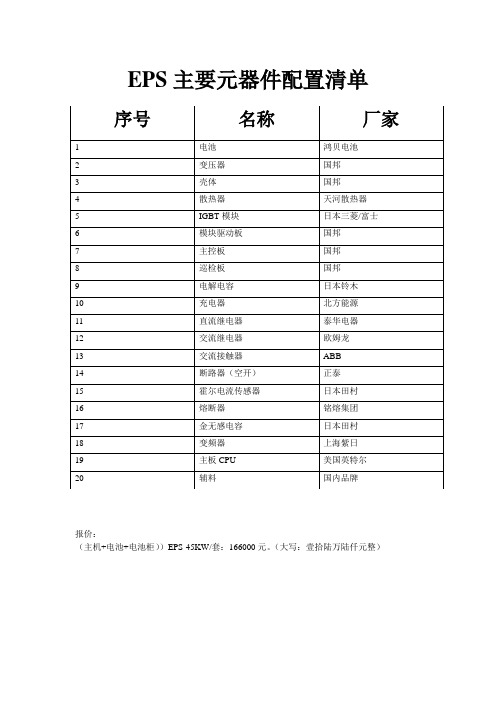
EPS主要元器件配置清单报价:(主机+电池+电池柜))EPS-45KW/套:166000元。
(大写:壹拾陆万陆仟元整)消防应急电源的技术参数:WGBS系列EPS消防应急电源性能说明一、产品概述消防集中应急电源系统也称为EPS,专门为消防设备发生火情或其他紧急情况下,为标志灯、照明灯及其他设施提供电源而设计,当电网电压正常时,电网交流电源经本设备内互投装置直接给负载供电,同时本设备内的充电器对电池组进行充电。
当电网停电或电网电压过低于15%或过高于15%额定电压时,本设备将立即切换到应急供电,有电池组设备用电源逆变器输出交流续给负载提供电源,使用本设备请详细阅读使用说明书。
二、注意事项1、在安装使用前必须详细阅读使用说明书。
2、遵照指示步骤进行正确操作。
3、布线请依照说明施工。
4、妥善保管使用说明书,作为日后参考。
5、出现问题请速与本公司联系。
6、按照说明书要求,对设备进行日常维护。
7、负载功率不应超过本机额定功率,否则会造成自动保护或本机故障。
三、储存搬运说明1、产品存放环境温度为-10~55℃,相对湿度<20%。
2、产品存放不含酸性、碱性以及其他腐蚀性及易燃易爆气体的气体环境下。
3、产品的存放应置于防尘、防雨、防潮的环境内,设备暂存时用高于10cm的木踏板,将设备与地面隔离。
4、搬运设备时应采用机械设备平行搬运、严禁倒置。
5、搬运设备落地时应小心轻放,切勿重放。
四、安装说明1、整机应置于水平安装、避免放置阳光直射寸淋或潮湿处。
2、保持设备良好的通风环境避免置于会腐蚀的气体处,工作环境温度0℃~40℃。
3、检查电池有无损坏现象,再以串联的方式将电池连接号,串联后的电压为DC492V。
4、电池上的“+”“-”标志接好连线请切勿接反。
5、请使用与之相匹配的专用插座或电缆线再遵照线路图的说明书将市电的输入输出接好。
五、EPS原理图(见图)六、技术特性1、操作简介,维护方便。
2、高度可靠的安全保护,采用变频输出技术保证为您的负载提供可靠能源,使其在停电时正常工作。
ABS、EBS、ESC产品介绍

4.EBS可以优先使用缓速器等辅助制动 系统,如减速不够再使用行车制动系统
5
4
5.EBS可以不断调整制动压力,使实际 的减速度与期望的减速度一致
6.EBS可以通过计算自动分配前后轴,
电子稳定性控 制ABS+ESC
1. RSC车辆防侧翻系统. 2. 方向控制:监测车辆转弯角度、偏航率。当 车辆偏航时,功能激活,通过发动机制动或者 车轮制动,防止车辆偏航,控制车辆按照驾驶 员需求驾驶行使, 提高车辆在转弯时的稳定性.
−减少车辆行使不稳定和70%的翻车事故 −避免车辆出现转向不足,转向过度,主
易于拓展新的功能 可满足新的欧洲法规
CAN通讯
EBS具有更多的功能
14
减速度 [m/ss] 压力 [bar] 行车制动
辅助制动集成示例
4,0
车速
3,5
3
总制动
2,5
2
辅助制动
1,5
1
Z_ist
0,5
p_Friction brake M_DBremsen (Retarder)
v_vehicle
0
时t 间
ECU接收制动信号传输器(脚阀)传输的制动需求,在确保安 全的前提下,优先使用辅助制动,辅助制动力不够,再使用行 车制动。
尽可能多的使用无磨损制动,减少摩擦 片磨损 降低车辆使用、维护费用
CAN通讯
通过控制挂车控制阀的输出压力,实现主挂车一致性; 主挂 车都带EBS系统,通过减速度来调节主挂车的一致性; 如果挂 车只带ABS系统,通过标定越前量和压力梯度曲线 专为中国市场开发的Load-frame功能,在挂车不带任何轮速 传感器时,可将挂车作为载荷计算,进行制动力分配,采用闭
乐珀尔蓄电池合格证模板
乐珀尔蓄电池合格证模板
摘要:
1.乐珀尔蓄电池概述
2.乐珀尔蓄电池的参数及规格
3.乐珀尔蓄电池的标准
4.乐珀尔蓄电池的优点
5.乐珀尔蓄电池的合格证模板
正文:
乐珀尔蓄电池是一种高品质的蓄电池产品,其采用了独特的多元合金配方,并利用高性能设备和严格的温度控制技术,使得其板栅不仅厚度、重量均匀性好,而且耐腐蚀性强,浮充寿命长。
乐珀尔蓄电池的参数及规格如下:电池型号为6-gfm-38,电压为12V,电流为38A,容量为38Ah。
这款蓄电池的板栅采用了多元合金配方,使得其具有良好的耐腐蚀性和较长的浮充寿命。
乐珀尔蓄电池符合多项标准,包括JIS C 8707-1992 阴极吸收式密封固定型铅酸蓄电池标准、JB/T 8451-96中华人民共和国机械行业标准以及YD/T 799-2006 通信电源设备抗地震检测规范等。
乐珀尔蓄电池的优点主要体现在其独特的多元合金配方、严格的温度控制以及良好的耐腐蚀性和浮充寿命。
这些优点使得乐珀尔蓄电池在众多蓄电池产品中脱颖而出,成为了消费者的首选。
乐珀尔蓄电池的合格证模板如下:
【乐珀尔蓄电池合格证】
电池型号:6-gfm-38
电压:12V
电流:38A
容量:38Ah
项目| 规格| 测试结果
--- | --- | ---
电压| 12V | 12.05V
电流| 38A | 38.5A
容量| 38Ah | 38.5Ah
浮充电压| 14.1V | 14.15V
充电时间| 6 小时| 5 小时45 分钟
放电时间| 3 小时| 3 小时15 分钟
结论:根据测试结果,该批乐珀尔蓄电池符合相关标准,质量合格。
防硫化电阻产品特性

RMS10JT1R5 RMS10JT183 RMS10JT185 RMS10JT152 RMS10JT150 RMS10JT123 RMS10JT123 RMS10JT132 RMS10JT154 RMS10JT150 RMS10JT123 RMS10JT101 RMS10JT122 RMS10JT122 RMS10JT123 RMS10JT201 RMS10JT201 RMS10JT202 RMS10JT202 RMS10JT202 RMS10JT243 RMS10JT242 RMS10JT243 RMS10JT243 RMS10JT243 RMS10JT244 RMS10JT272 RMS10JT244 RMS10JT304 RMS10JT272 RMS10JT2R0 RMS10JT302 RMS10JT2R0 RMS10JT3R0 RMS10JT330 RMS10JT472 RMS10JT475 RMS10JT511 RMS10JT512 RMS10JT512 RMS10JT514 RMS10JT514 RMS10JT514 RMS10JT681 RMS10JT6R8 RMS10JT823 RMS10JT750 RMS10JT512 RMS10JT201 RMS10JT823 RMS10JT912 RMS10JT913 更多防硫化贴片电阻,抗硫化精密电阻,抗硫化低温漂电阻,防腐蚀低温漂电阻,防腐蚀精密电阻 厚膜抗硫化电阻,薄膜抗硫化电阻,高精度抗硫化电阻,抗硫化晶片电阻 欢迎来电洽询深圳市捷比信实业有限公司
功2W
RMS04JT105 RMS04JT131 RMS04JT203 RMS04JT182 RMS04JT203 RMS04JT224 RMS04JT221 RMS04JT221 RMS04JT221 RMS04JT223 RMS04JT224 RMS04JT224 RMS04JT222 RMS04JT223 RMS04JT224 RMS04JT272 RMS04JT302 RMS04JT334 RMS04JT360 RMS04JT432 RMS04JT432 RMS04JT433 RMS04JT5R6 RMS04JT620 RMS04JT682 RMS04JT7R5 RMS04JT7R5 RMS04JT822 RMS04JT8R2 RMS04JT682 RMS06FT10R0 RMS04JT821 RMS06FT10R0 RMS06FT10R0 RMS06FT10R0 RMS04JT912 RMS04JT9R1 RMS06FT1503 RMS06FT1503 RMS06FT1503 RMS06FT1801 RMS06FT1503 RMS06FT1801 RMS06FT33R0 RMS06FT33R0 RMS06FT33R0 RMS06FT33R0 RMS06FT2001 RMS06JT155 RMS06FT3901 RMS06FT4302 RMS06FT4700 RMS06FT4701 RMS06FT47R0 RMS06FT4700 RMS06FT4700 RMS06FT4701 RMS06FT4701 RMS06FT4701
NRG ELX1225 2022年7月技术数据:EPoxy封封闭径向NTC热感应器商品介绍说明书

NRGEpoxy sealed radial lead NTC thermistorProduct features• Epoxy sealed radial NTC thermistor • Temperature sensing, quick response time • Bead with ring lug• Wide resistance range:1 k Ω to 470 kΩ•Non-linear change in resistance vs temperaturePb HALOGENHF FREEPackaging information• Bulk, Type 3: 250 parts per poly bag •Bulk, Others: 500 parts per poly bagT able 1. Part numberingNRG a xxy b xxxx Bx c xFamily nameNRGRing lug type1/2/3/ (See mechanicalparameters for details)Resistancexxy= x.x * 10y Ωex: 103 = 1.0 * 103 = 1000 ΩResistance tolerance codeF = ±1%, H = ±3%Beta tolerance codeF = ±1%,G = ±2%,H = ±3%Beta type codeB1 = 25/50, B2 = 25/85Beta value ex: 3465, 4215, etcLead styleDifferent lead dimensionsApplications• Industrial Process Control • Commercial appliances•Battery, supercapacitor and energy storage systems• Uninterruptible power supplies • Consumer appliances •Medical devices•Heating, ventilation and air conditioning, Refrigeration (HVACR)• Food service equipment • IoT• White goods/household appliances •Computer and peripheral productsEnvironmental compliance and general specificationsSee electrical specification table for option details2Technical Data ELX1225Effective July 2022NRGEpoxy sealed radial lead NTC thermistor/electronicsMechanical parameters- mmLug type 1Lug type 2Lug type 3• 26AWG black Insulated lead wire with terminals tinned3Technical Data ELX1225Effective July 2022NRGEpoxy sealed radial lead NTC thermistor /electronics Electrical specificationsPart numberZero power resistance @ 25°C R 25 (kΩ)Ring lug type(Part number code)R 25Tolerance (Part number code)Beta type (Part number code)Beta value (K)Betatolerance (Part number code)Maximum power@ +25°C P max (mW)Dissipationfactor (mW/°C)Thermaltime constant T (second)Operation temperature TL~TU(°C)NRGa103bxxxxBxc 1(1), (2), (3)±1% (F) ,±3% (H)25/85 (B2)3435±2% (G), ±3% (H)50≥ 2.5 (type3) ≥ 3.0 (others)≤ 10 (type3) ≤ 9 (others)-30 to +105NRGa683bxxxxBxc 6.8(1), (2), (3)±1% (F) ,±3% (H)25/85 (B2)3470±2% (G), ±3% (H)50≥ 2.5 (type3) ≥ 3.0 (others)≤ 10 (type3) ≤ 9 (others)-30 to +105NRGa683bxxxxBxc 6.8(1), (2), (3)±1% (F) ,±3% (H)25/85 (B2)3975±2% (G), ±3% (H)50≥ 2.5 (type3) ≥ 3.0 (others)≤ 10 (type3) ≤ 9 (others)-30 to +105NRGa104bxxxxBxc 10(1), (2), (3)±1% (F) ,±3% (H)25/85 (B2)3435±1% (F), ±3% (H)50≥ 2.5 (type3) ≥ 3.0 (others)≤ 10 (type3) ≤ 9 (others)-30 to +105NRGa104bxxxxBxc 10(1), (2), (3)±1% (F) ,±3% (H)25/85 (B2)3975±1% (F), ±3% (H)50≥ 2.5 (type3) ≥ 3.0 (others)≤ 10 (type3) ≤ 9 (others)-30 to +105NRGa203bxxxxBxc 2(1), (2), (3)±1% (F) ,±3% (H)25/85 (B2)3435±1% (F), ±3% (H)50≥ 2.5 (type3) ≥ 3.0 (others)≤ 10 (type3) ≤ 9 (others)-30 to +105NRGa224bxxxxBxc 22(1), (2), (3)±1% (F) ,±3% (H)25/85 (B2)3740±1% (F), ±3% (H)50≥ 2.5 (type3) ≥ 3.0 (others)≤ 10 (type3) ≤ 9 (others)-30 to +105NRGa334bxxxxBxc 33(1), (2), (3)±1% (F) ,±3% (H)25/85 (B2)3975±1% (F), ±3% (H)50≥ 2.5 (type3) ≥ 3.0 (others)≤ 10 (type3) ≤ 9 (others)-30 to +105NRGa474bxxxxBxc 47(1), (2), (3)±1% (F) ,±3% (H)25/85 (B2)4090±1% (F), ±3% (H)50≥ 2.5 (type3) ≥ 3.0 (others)≤ 10 (type3) ≤ 9 (others)-30 to +105NRGa504bxxxxBxc 50(1), (2), (3)±1% (F) ,±3% (H)25/85 (B2)3950±1% (F), ±3% (H)50≥ 2.5 (type3) ≥ 3.0 (others)≤ 10 (type3) ≤ 9 (others)-30 to +105NRGa504bxxxxBxc 50(1), (2), (3)±1% (F) ,±3% (H)25/85 (B2)4050±1% (F), ±3% (H)50≥ 2.5 (type3) ≥ 3.0 (others)≤ 10 (type3) ≤ 9 (others)-30 to +105NRGa105bxxxxBxc 100(1), (2), (3)±1% (F) ,±3% (H)25/85 (B2)4000±1% (F), ±3% (H)50≥ 2.5 (type3) ≥ 3.0 (others)≤ 10 (type3) ≤ 9 (others)-30 to +105NRGa105bxxxxBxc 100(1), (2), (3)±1% (F) ,±3% (H)25/85 (B2)4190±2% (G), ±3% (H)50≥ 2.5 (type3) ≥ 3.0 (others)≤ 10 (type3) ≤ 9 (others)-30 to +105NRGa105bxxxxBxc 100(1), (2), (3)±1% (F) ,±3% (H)25/85 (B2)4360±2% (G), ±3% (H)50≥ 2.5 (type3) ≥ 3.0 (others)≤ 10 (type3) ≤ 9 (others)-30 to +105NRGa475bxxxxBxc 470(1), (2), (3)±1% (F) ,±3% (H)25/85 (B2)4570±2% (G), ±3% (H)50≥ 2.5 (type3) ≥ 3.0 (others)≤ 10 (type3) ≤ 9 (others)-30 to +105NRGa203bxxxxBxc 2(1), (2), (3)±1% (F) ,±3% (H)25/50 (B1)3380±2% (G), ±3% (H)50≥ 2.5 (type3) ≥ 3.0 (others)≤ 10 (type3) ≤ 9 (others)-30 to +105NRGa503bxxxxBxc 5(1), (2), (3)±1% (F) ,±3% (H)25/50 (B1)3420±2% (G), ±3% (H)50≥ 2.5 (type3) ≥ 3.0 (others)≤ 10 (type3) ≤ 9 (others)-30 to +105NRGa503bxxxxBxc 5(1), (2), (3)±1% (F) ,±3% (H)25/50 (B1)3900±2% (G), ±3% (H)50≥ 2.5 (type3) ≥ 3.0 (others)≤ 10 (type3) ≤ 9 (others)-30 to +105NRGa104bxxxxBxc 10(1), (2), (3)±1% (F) ,±3% (H)25/50 (B1)3380±1% (F), ±3% (H)50≥ 2.5 (type3) ≥ 3.0 (others)≤ 10 (type3) ≤ 9 (others)-30 to +105NRGa104bxxxxBxc 10(1), (2), (3)±1% (F) ,±3% (H)25/50 (B1)4000±1% (F), ±3% (H)50≥ 2.5 (type3) ≥ 3.0 (others)≤ 10 (type3) ≤ 9 (others)-30 to +105NRGa104bxxxxBxc 10(1), (2), (3)±1% (F) ,±3% (H)25/50 (B1)3950±1% (F), ±3% (H)50≥ 2.5 (type3) ≥ 3.0 (others)≤ 10 (type3) ≤ 9 (others)-30 to +105NRGa684bxxxxBxc 68(1), (2), (3)±1% (F) ,±3% (H)25/50 (B1)3950±1% (F), ±3% (H)50≥ 2.5 (type3) ≥ 3.0 (others)≤ 10 (type3) ≤ 9 (others)-30 to +105NRGa224bxxxxBxc 22(1), (2), (3)±1% (F) ,±3% (H)25/50 (B1)3700±1% (F), ±3% (H)50≥ 2.5 (type3) ≥ 3.0 (others)≤ 10 (type3) ≤ 9 (others)-30 to +105NRGa474bxxxxBxc 47(1), (2), (3)±1% (F) ,±3% (H)25/50 (B1)3950±1% (F), ±3% (H)50≥ 2.5 (type3) ≥ 3.0 (others)≤ 10 (type3) ≤ 9 (others)-30 to +105NRGa474bxxxxBxc 47(1), (2), (3)±1% (F) ,±3% (H)25/50 (B1)4020±1% (F), ±3% (H)50≥ 2.5 (type3) ≥ 3.0 (others)≤ 10 (type3) ≤ 9 (others)-30 to +105NRGa105bxxxxBxc 100(1), (2), (3)±1% (F) ,±3% (H)25/50 (B1)3950±1% (F), ±3% (H)50≥ 2.5 (type3) ≥ 3.0 (others)≤ 10 (type3) ≤ 9 (others)-30 to +105NRGa105bxxxxBxc 100(1), (2), (3)±1% (F) ,±3% (H)25/50 (B1)4120±2% (G), ±3% (H)50≥ 2.5 (type3) ≥ 3.0 (others)≤ 10 (type3) ≤ 9 (others)-30 to +105NRGa225bxxxxBxc220(1), (2), (3)±1% (F) ,±3% (H)25/50 (B1)4370±2% (G), ±3% (H)50≥ 2.5 (type3) ≥ 3.0 (others)≤ 10 (type3) ≤ 9 (others)-30 to +105a= Enter ring lug type from table above (1, 2, 3) See Mechanical parameters for lug type details b= Enter resistance tolerance code from table above (F = ±1%, H = ±3%)Bx= Enter Beta type code from table above (B1 = 25/50, B2 = 25/85)c= Enter Beta tolerance code from table above (F = ±1%, G = ±2%, H = ±3%)4Technical Data ELX1225Effective July 2022NRGEpoxy sealed radial lead NTC thermistor/electronicsPart number NRG1033435NRG2033435NRG1043435NRG1043975NRG2243740NRG3343975B typeB25/85B25/85B25/85B25/85B25/85B25/85Temperature (°C)Resistance (kΩ)Resistance (kΩ)Resistance (kΩ)Resistance (kΩ)Resistance (kΩ)Resistance(kΩ)-4020.089532539.55751116.42-3919.1491.71304.8337.47541.351045.23-3818.2488.53286.0135.55509.86978.99-3717.3885.46268.4533.74480.37917.34-3616.5682.51252.0632.03452.75859.93-3515.7879.66236.7630.41426.86806.46-3415.0476.9222.4728.88402.6756.62-3314.3374.25209.1127.43379.85710.15-3213.6671.69196.6326.05358.5666.81-3113.0169.22184.9524.76338.48626.37-3012.466.84174.0323.53319.68588.62-2911.8264.54163.8222.36302.02553.36-2811.2662.32154.2521.26285.44520.42-2710.7360.18145.320.22269.86489.64-2610.2358.11136.9119.23255.21460.85-259.7556.12129.0518.3241.44433.93-249.2954.19121.6817.41228.49408.73-238.8552.34114.7816.57216.3385.14-228.4450.54108.315.77204.83363.06-218.0448.81102.2215.02194.03342.36-207.6747.1496.5114.3183.86322.97-197.3145.5391.1513.62174.28304.79-18 6.9643.9786.1212.98165.24287.74-17 6.6442.4781.412.37156.73271.74-16 6.3341.0276.9511.79148.7256.72-15 6.0339.6272.7811.24141.13242.62-14 5.7538.2768.8510.72133.98229.37-13 5.4936.9665.1610.22127.23216.93-12 5.2335.761.689.75120.86205.23-11 4.9934.4958.419.31114.85194.23-10 4.7633.3155.338.88109.16183.88-9 4.5432.1852.428.48103.79174.15-8 4.3331.0849.698.198.71164.98-7 4.1330.0347.117.7393.91156.35-6 3.942944.687.3989.37148.22-5 3.7628.0242.397.0685.07140.56-4 3.5927.0740.23 6.7481133.34-3 3.4226.1538.19 6.4577.15126.54-2 3.2725.2636.27 6.1673.5120.12-1 3.1224.434.45 5.8970.05114.060 2.9823.5732.73 5.6466.78108.341 2.8522.7731.11 5.3963.67102.942 2.722229.58 5.1660.7397.843 2.621.2628.13 4.9457.9493.024 2.4820.5426.76 4.7355.2988.475 2.3719.8425.46 4.5352.7884.176 2.2719.1724.23 4.3450.480.17 2.1718.5223.07 4.1648.1476.258 2.0717.8921.97 3.9845.9972.69 1.9817.2920.93 3.8243.9469.1510 1.8916.7119.95 3.664265.8911 1.8116.1419.01 3.5140.1662.812 1.7315.618.13 3.3738.4159.8713 1.6615.0717.29 3.2336.7457.0914 1.5914.5616.49 3.135.1654.4615 1.5214.0715.74 2.9833.6551.9616 1.4613.615.02 2.8632.2149.5917 1.413.1414.34 2.7430.8547.35181.3412.713.7 2.6429.5445.21T emperature characteristics5Technical Data ELX1225Effective July 2022NRGEpoxy sealed radial lead NTC thermistor /electronics T emperature characteristics, cont.Part number NRG1033435NRG2033435NRG1043435NRG1043975NRG2243740NRG3343975B typeB25/85B25/85B25/85B25/85B25/85B25/85Temperature (°C)Resistance (kΩ)Resistance (kΩ)Resistance (kΩ)Resistance (kΩ)Resistance (kΩ)Resistance(kΩ)191.2812.2713.09 2.5328.343.1920 1.2311.8612.5 2.4327.1241.2721 1.1811.4611.95 2.342639.4422 1.1311.0811.43 2.2524.9337.7123 1.0910.710.93 2.1623.936.0624 1.0410.3510.45 2.0822.9334.49251101022233260.96039.679.57 1.9221.1131.58270.92249.349.16 1.8520.2730.23280.88629.038.77 1.7819.4628.95290.85178.738.4 1.7218.6927.73300.81888.448.05 1.6517.9526.56310.78738.167.71 1.5917.2525.45320.75737.897.39 1.5416.5724.4330.72877.627.09 1.4815.9323.39340.70137.37 6.8 1.4315.3222.43350.67527.13 6.52 1.3814.7321.52360.6502 6.89 6.25 1.3314.1720.64370.6263 6.666 1.2813.6319.81380.6035 6.44 5.76 1.2313.1219.02390.5817 6.23 5.53 1.1912.6318.26400.5608 6.03 5.31 1.1512.1517.54410.5409 5.83 5.1 1.1111.716.84420.5218 5.64 4.9 1.0711.2716.18430.5036 5.45 4.71 1.0410.8615.55440.4861 5.27 4.53110.4614.95450.4693 5.1 4.350.966810.0814.37460.4533 4.94 4.190.93459.7213.82470.438 4.78 4.030.90349.3713.3480.4233 4.62 3.870.87369.0412.79490.4092 4.47 3.730.84498.7212.31500.3957 4.33 3.590.81738.4111.85510.3827 4.19 3.450.79088.1111.41520.3703 4.05 3.330.76537.8310.99530.3584 3.92 3.20.74087.5610.58540.347 3.8 3.090.71737.310.19550.336 3.67 2.970.69467.059.82560.3255 3.56 2.870.6728 6.819.47570.3154 3.44 2.760.6518 6.589.13580.3057 3.34 2.660.6315 6.358.8590.2963 3.23 2.570.6121 6.148.49600.2874 3.13 2.480.5933 5.948.19610.2788 3.03 2.390.5753 5.747.9620.2705 2.93 2.310.5579 5.557.62630.2625 2.84 2.230.5411 5.377.36640.2549 2.75 2.150.525 5.197.1650.2475 2.67 2.080.5094 5.02 6.86660.2404 2.5920.4944 4.86 6.62670.2336 2.51 1.940.4799 4.7 6.4680.227 2.43 1.870.4659 4.55 6.18690.2207 2.35 1.810.4525 4.41 5.97700.2146 2.28 1.750.4395 4.27 5.77710.2087 2.21 1.690.4269 4.13 5.58720.203 2.14 1.630.4148 4.01 5.39730.1976 2.08 1.580.4031 3.88 5.21740.1923 2.02 1.530.3919 3.76 5.04750.1872 1.96 1.480.381 3.64 4.88760.1823 1.9 1.430.3704 3.53 4.72770.1776 1.84 1.380.3603 3.43 4.576Technical Data ELX1225Effective July 2022NRGEpoxy sealed radial lead NTC thermistor/electronicsT emperature characteristics, cont.Part number NRG1033435NRG2033435NRG1043435NRG1043975NRG2243740NRG3343975B typeB25/85B25/85B25/85B25/85B25/85B25/85Temperature (°C)Resistance (kΩ)Resistance (kΩ)Resistance (kΩ)Resistance (kΩ)Resistance (kΩ)Resistance(kΩ)780.173 1.79 1.340.3504 3.32 4.42790.1686 1.73 1.30.3409 3.22 4.28800.1643 1.68 1.260.3318 3.12 4.14810.1602 1.63 1.220.3229 3.03 4.01820.1562 1.59 1.180.3143 2.94 3.89830.1524 1.54 1.140.306 2.85 3.77840.1487 1.49 1.110.298 2.77 3.65850.1451 1.45 1.070.2902 2.69 3.54860.1416 1.41 1.040.2827 2.61 3.43870.1383 1.37 1.010.2754 2.54 3.32880.135 1.330.97640.2684 2.46 3.22890.1319 1.290.9470.2615 2.39 3.12900.1288 1.260.91850.2549 2.32 3.03910.1259 1.220.89110.2486 2.26 2.94920.123 1.190.86470.2424 2.2 2.85930.1202 1.150.83910.2364 2.13 2.77940.1176 1.120.81450.2305 2.07 2.68950.115 1.090.79070.2249 2.02 2.61960.1124 1.060.76780.2194 1.96 2.53970.11 1.030.74560.2141 1.91 2.46980.107610.72420.209 1.86 2.39990.10530.97750.70350.204 1.81 2.321000.10310.95130.68350.1992 1.76 2.251010.10090.9260.66410.1945 1.71 2.191020.09880.90140.64550.19 1.66 2.121030.09680.87770.62740.1856 1.62 2.071040.09480.85470.610.1813 1.58 2.011050.09290.83240.59310.1771 1.54 1.957Technical Data ELX1225Effective July 2022NRGEpoxy sealed radial lead NTC thermistor /electronics T emperature characteristicsPart number NRG1054000NRG1054190NRG1054360NRG2033380NRG1043380NRG1044000B type B25/85B25/85B25/85B25/50B25/50B25/50Temperature (°C)Resistance (kΩ)Resistance (kΩ)Resistance (kΩ)Resistance (kΩ)Resistance (kΩ)Resistance (kΩ)-4031003300360039.8195325-392910.563098.573377.1937.69184.63305.06-382733.692910.373169.1435.71174.87286.45-372568.52734.472974.7933.84165.67269.05-362414.172570.022793.1932.07157.01252.8-352269.932416.232623.4730.41148.84237.61-342135.072272.352464.7828.84141.14223.4-332008.932137.72316.3727.36133.89210.11-321890.92011.652177.5425.96127.04197.67-311780.431893.632047.6324.64120.58186.03-3016771783.071926.0223.39114.48175.13-291580.121679.481812.1622.21108.73164.93-281489.351582.391705.5121.1103.29155.36-271404.261491.361605.6120.0598.15146.4-261324.491405.991511.9819.0593.3138-251249.661325.91424.2218.1188.71130.12-241179.461250.741341.9317.2284.38122.73-231113.571180.21264.7416.3880.28115.8-221051.71113.951192.3315.5876.39109.29-21993.61051.741124.3814.8372.72103.18-20939.01993.291060.5914.1169.2597.44-19887.7938.351000.713.4465.9692.04-18839.47886.71944.4412.862.8486.98-17794.11838.15891.612.1959.8882.21-16751.44792.48841.9311.6257.0977.74-15711.28749.5795.2511.0754.4373.52-14673.48709.06751.3610.5651.9269.56-13637.88670.98710.0810.0749.5365.83-12604.36635.13671.259.647.2762.32-11572.77601.36634.79.1645.1259.01-10542.99569.54600.318.7443.0855.9-9514.92539.56567.938.3541.1552.96-8488.45511.29537.447.9739.3150.2-7463.47484.63508.717.6137.5647.59-6439.9459.49481.657.2735.945.13-5417.65435.77456.14 6.9534.3342.81-4396.65413.38432.1 6.6432.8340.62-3376.81392.25409.42 6.3531.438.56-2358.06372.29388.04 6.0730.0536.61-1340.35353.45367.87 5.8128.7634.770323.6335.65348.83 5.5627.5333.031307.76318.82330.86 5.3226.3631.382292.78302.92313.9 5.0925.2529.833278.61287.88297.88 4.8824.1928.364265.2273.67282.74 4.6723.1826.975252.5260.22268.45 4.4822.2225.666240.48247.49254.93 4.2921.324.427229.09235.44242.16 4.1120.4323.248218.3224.04230.09 3.9419.5922.139208.07213.25218.66 3.7818.821.0710198.37203.02207.86 3.6318.0420.0711189.18193.33197.64 3.4817.3219.1312180.46184.15187.96 3.3416.6318.2313172.19175.45178.81 3.2115.9717.3814164.33167.2170.13 3.0815.3416.5715156.88159.38161.92 2.9614.7315.8116149.81151.96154.14 2.8414.1615.0817143.08144.92146.77 2.7313.6114.418136.7138.24139.78 2.6213.0913.748Technical Data ELX1225Effective July 2022NRGEpoxy sealed radial lead NTC thermistor/electronicsT emperature characteristics, cont.Part number NRG1054000NRG1054190NRG1054360NRG2033380NRG1043380NRG1044000B type B25/85B25/85B25/85B25/50B25/50B25/50Temperature (°C)Resistance (kΩ)Resistance (kΩ)Resistance (kΩ)Resistance (kΩ)Resistance (kΩ)Resistance (kΩ)19130.63131.9133.16 2.5212.5813.1220124.87125.87126.88 2.4212.112.5321119.38120.16120.93 2.3311.6511.9722114.17114.73115.28 2.2411.2111.4423109.21109.57109.92 2.1610.7910.9424104.49104.66104.83 2.0810.3810.4625100100100210102695.7395.5795.41 1.939.639.572791.6691.3591.06 1.859.289.152887.7887.3486.92 1.798.948.762984.0983.5382.99 1.728.628.393080.5779.979.26 1.668.318.033177.2176.4575.71 1.68.017.693274.0273.1672.34 1.547.727.373370.9770.0269.13 1.497.457.063468.0667.0466.07 1.447.19 6.773565.2964.263.17 1.39 6.94 6.493662.6461.4960.41 1.34 6.69 6.223760.1258.9157.78 1.29 6.46 5.973857.7156.4555.27 1.25 6.24 5.723955.4154.152.89 1.2 6.03 5.494053.2151.8650.62 1.16 5.82 5.274151.1149.7348.46 1.12 5.62 5.064249.147.6946.4 1.09 5.43 4.864347.1845.7544.43 1.05 5.25 4.674445.3543.8942.56 1.01 5.08 4.484543.642.1240.780.9809 4.91 4.314641.9240.4339.080.9487 4.75 4.144740.3238.8137.450.9178 4.59 3.984838.7837.2735.910.8881 4.44 3.834937.3235.7934.430.8595 4.3 3.685035.9134.3833.020.832 4.16 3.545134.5733.0431.680.8056 4.03 3.415233.2831.7530.390.7801 3.9 3.285332.0530.5229.160.7556 3.78 3.165430.8629.3427.990.7321 3.66 3.045529.7328.2126.870.7094 3.54 2.935628.6527.1325.810.6875 3.43 2.825727.6126.124.780.6665 3.33 2.725826.6125.1123.810.6462 3.22 2.625925.6524.1722.870.6266 3.12 2.526024.7423.2621.980.6078 3.03 2.436123.8622.3921.130.5896 2.94 2.356223.0121.5620.310.5721 2.85 2.266322.220.7619.530.5553 2.76 2.186421.432018.780.539 2.68 2.116520.6819.2718.060.5233 2.6 2.036619.9618.5717.380.5081 2.52 1.966719.2817.916.720.4935 2.45 1.896818.6117.2516.10.4794 2.38 1.836917.9816.6315.490.4658 2.31 1.777017.3716.0414.920.4526 2.24 1.717116.7815.4714.360.4399 2.18 1.657216.2214.9213.840.4277 2.12 1.597315.6814.413.330.4158 2.06 1.547415.1613.8912.840.40442 1.497514.6513.4112.370.3933 1.94 1.447614.1712.9411.930.3826 1.89 1.397713.7112.511.50.3722 1.84 1.359Technical Data ELX1225Effective July 2022NRGEpoxy sealed radial lead NTC thermistor /electronics T emperature characteristics, cont.Part number NRG1054000NRG1054190NRG1054360NRG2033380NRG1043380NRG1044000B type B25/85B25/85B25/85B25/50B25/50B25/50Temperature (°C)Resistance (kΩ)Resistance (kΩ)Resistance (kΩ)Resistance (kΩ)Resistance (kΩ)Resistance (kΩ)7813.2612.0711.090.3622 1.79 1.37912.8311.6610.690.3526 1.74 1.268012.4211.2610.310.3432 1.69 1.228112.0210.889.950.3342 1.64 1.188211.6310.519.60.3254 1.6 1.148311.2610.169.260.3169 1.56 1.118410.919.828.940.3087 1.51 1.078510.579.58.630.3008 1.47 1.048610.239.188.330.2931 1.44 1.01879.928.888.050.2856 1.40.9746889.618.597.770.2784 1.360.9445899.318.317.510.2714 1.330.9156909.038.047.250.2646 1.290.8877918.757.787.010.2581 1.260.8608928.487.53 6.780.2517 1.230.8349938.237.29 6.550.2455 1.190.8098947.987.06 6.330.2396 1.160.7857957.74 6.84 6.120.2338 1.140.7624967.51 6.62 5.920.2281 1.110.7399977.29 6.42 5.730.2227 1.080.7182987.07 6.22 5.540.2174 1.050.697299 6.87 6.02 5.360.2123 1.030.677100 6.67 5.84 5.190.207310.6575101 6.47 5.66 5.020.20240.9770.6386102 6.29 5.48 4.860.19770.95330.6204103 6.1 5.32 4.710.19320.93030.6027104 5.93 5.16 4.560.18870.90790.5857105 5.765 4.420.18440.88630.569310Technical Data ELX1225Effective July 2022NRGEpoxy sealed radial lead NTC thermistor/electronicsT emperature characteristicsPart number NRG1043950NRG2243700NRG1053950NRG1054120NRG2254370B typeB25/50B25/50B25/50B25/50B25/50Temperature (°C)Resistance (kΩ)Resistance (kΩ)Resistance (kΩ)Resistance (kΩ)Resistance(kΩ)-403252056.32300032508728.94-39304.831932.462819.843053.328171.87-38286.011816.682651.42869.427652.85-37268.461708.422493.872697.437169.11-36252.071607.152346.482536.526718.12-35236.771512.42208.542385.946297.51-34222.481423.72079.412244.975905.11-33209.121340.651958.462112.965538.92-32196.641262.861845.161989.315197.08-31184.961189.971738.981873.454877.85-30174.041121.661639.441764.864579.66-29163.831057.611546.091663.054301.03-28154.26997.531458.531567.574040.59-27145.31941.171376.3614783797.08-26136.92888.281299.231393.953569.34-25129.06838.621226.811315.063356.26-24121.69791.991158.781240.993156.86-23114.78748.181094.871171.432970.19-22108.3707.021034.81106.072795.39-21102.22668.32978.321044.662631.66-2096.52631.94925.21986.932478.25-1991.16597.72875.25932.662334.46-1886.13565.53828.23881.612199.66-1781.4535.23783.97833.582073.24-1676.96506.7742.3788.391954.64-1572.78479.84703.05745.851843.36-1468.86454.53666.07705.81738.91-1365.16430.69631.22668.081640.85-1261.69408.22598.37632.551548.75-1158.41387.03567.39599.061462.23-1055.33367.05538.17567.51380.93-952.43348.19510.59537.751304.51-849.69330.41484.57509.691232.66-747.12313.62460483.221165.09-644.69297.76436.81458.241101.53-542.4282.79414.89434.671041.71-440.23268.64394.19412.42985.41-338.19255.28374.62391.4932.4-236.27242.64356.11371.56882.49-134.45230.7338.62352.81835.46032.73219.4322.07335.09791.15131.11208.71306.41318.34749.39229.58198.59291.59302.5710.02328.13189.02277.56287.53672.9426.76179.96264.28273.36637.88525.46171.37251.69259.96604.84624.23163.24239.77247.27573.66723.07155.53228.48235.26544.22821.98148.23217.77223.89516.43920.93141.31207.61213.12490.181019.95134.74197.98202.92465.381119.02128.51188.84193.25441.951218.13122.6180.18184.08419.811317.29117171.95175.4398.871416.5111.67164.13167.16379.071515.74106.62156.72159.35360.341615.02101.82149.67151.94342.621714.3497.26142.97144.9325.851813.792.93136.61138.23309.9811Technical Data ELX1225Effective July 2022NRG Epoxy sealed radial lead NTC thermistor /electronics T emperature characteristics, cont.Part number NRG104 3950NRG2243700NRG1053950NRG1054120NRG2254370B type B25/50B25/50B25/50B25/50B25/50Temperature (°C)Resistance (kΩ)Resistance (kΩ)Resistance (kΩ)Resistance (kΩ)Resistance (kΩ)1913.0988.81130.56131.89294.952012.584.89124.81125.87280.722111.9581.17119.35120.16267.242211.4377.63114.14114.73254.462310.9374.26109.19109.57242.362410.4571.05104.48104.66230.88251068100100220269.5765.0995.7395.57209.68279.1662.3391.6691.35199.89288.7759.6987.7987.34190.6298.457.1884.183.52181.79308.0554.7980.5879.89173.42317.7152.5177.2376.44165.48327.3950.3374.0373.14157.93337.0948.2670.9870.01150.7734 6.846.2868.0867.02143.9635 6.5244.465.364.18137.4936 6.2542.662.6561.47131.3437640.8860.1358.88125.4938 5.7639.2457.7156.42119.9339 5.5337.6755.4154.07114.6440 5.3136.1753.2151.83109.6141 5.134.7451.149.69104.8242 4.933.3849.0947.65100.2643 4.7132.0747.1745.7195.9244 4.5330.8245.3443.8591.7945 4.3529.6343.5842.0887.8546 4.1928.4941.940.3884.147 4.0327.440.338.7780.5348 3.8726.3538.7637.2277.1349 3.7325.3637.2935.7473.8850 3.5924.435.8834.3370.7951 3.4523.4834.5332.9867.8452 3.3322.6133.2431.6965.0353 3.221.7732.0130.4662.3454 3.0920.9630.8229.2859.7855 2.9720.1929.6928.1557.3356 2.8719.4528.627.075557 2.7618.7527.5626.0452.7758 2.6618.0726.5625.0550.6559 2.5717.4225.624.148.6160 2.4816.7924.6823.246.6761 2.3916.1923.822.3344.8262 2.3115.6222.9621.543.0463 2.2315.0722.1520.741.3564 2.1514.5421.3719.9439.7365 2.0814.0320.6219.2138.1866213.5419.918.536.767 1.9413.0819.2117.8335.2868 1.8712.6318.5517.1933.9269 1.8112.1917.9116.5732.6270 1.7511.7817.315.9731.3871 1.6911.3816.7115.430.1972 1.631116.1514.8629.0573 1.5810.6315.6114.3327.9674 1.5310.2715.0913.8326.9175 1.489.9314.5813.3425.9176 1.439.614.112.8824.9577 1.389.2913.6412.4324.03Eaton Electronics Division 1000 Eaton Boulevard Cleveland, OH 44122United States /electronics© 2022 Eaton All Rights Reserved Printed in USA Publication No. ELX1225 BU-ELX22085July 2022NRG Epoxy sealed radial lead NTC thermistor Technical Data ELX1225Effective July 2022Life Support Policy: Eaton does not authorize the use of any of its products for use in life support devices or systems without the express written approval of an officer of the Company. Life support systems are devices which support or sustain life, and whose failure to perform, when properly used in accordance with instructions for use provided in the labeling, can be reasonably expected to result in significant injury to the user.Eaton reserves the right, without notice, to change design or construction of any products and to discontinue or limit distribution of any products. Eaton also reserves the right to change or update, without notice, any technical information contained in this bulletin.Eaton is a registered trademark.All other trademarks are property of their respective owners.Follow us on social media to get thelatest product and support information.Manual solder+360 °C, 2.5 seconds maximum by soldering iron, distance between soldering position and coating 10 mm minimum.T emperature characteristics, cont.Part number NRG104 3950NRG2243700NRG1053950NRG1054120NRG2254370B type B25/50B25/50B25/50B25/50B25/50Temperature (°C)Resistance (kΩ)Resistance (kΩ)Resistance (kΩ)Resistance (kΩ)Resistance (kΩ)78 1.348.9813.191223.15791.38.6912.7611.5922.31801.268.4112.3411.221.5811.228.1411.9510.8220.72821.187.8811.5610.4519.97831.147.6311.1910.119.26841.117.3910.849.7618.57851.077.1510.499.4317.91861.04 6.9310.169.1217.28871.01 6.719.848.8216.67880.9762 6.59.548.5316.09890.9467 6.39.248.2515.53900.9183 6.118.957.9814.99910.8909 5.928.687.7214.47920.8644 5.748.417.4813.97930.8389 5.578.167.2413.49940.8143 5.47.91713.04950.7905 5.247.67 6.7812.59960.7675 5.087.44 6.5712.17970.7454 4.937.22 6.3611.76980.724 4.787 6.1611.37990.7033 4.64 6.8 5.9710.991000.6833 4.51 6.6 5.7810.631010.6639 4.37 6.4 5.6110.281020.6453 4.25 6.22 5.439.941030.6272 4.13 6.04 5.279.611040.6098 4.01 5.86 5.119.31050.5929 3.89 5.69 4.959。
EPS检测报告

测试条件
测试项目
测试指标
调试记录
直 流 状 态
逆变输出电压
220V± 3%
219V
逆变输出频率
50Hz± 1%
50Hz
波形失真度
<3%
<3%
过载保护
≥3KW
>3KW
蓄电池输入额定电压
DC192V
192V
蓄电池低压保护
168Vdc±3V
169V
蓄电池低压回滞
192Vdc±3V
192V
符合要求
丝印、机器表面
丝印准确、清晰,表面干净、清洁,无损伤
符合要求
螺丝
安装牢固,无损伤
符合要求
噪音
≤50db
符合要求
操作时间
2016年9月8日
判定结果
合格
直流高压保护
280Vdc±3V
281V
交 流 状 态
交流输入电压
380常(异常---正常)
10次切换/满载状态
正常
外 观
指示灯
亮度正常、均匀
符合要求
液晶屏
显示正确,操作准确、灵活
符合要求
开关、按钮
位置正确,操作准确、灵活
符合要求
连接工艺、端子
连接牢固、可靠,工艺美观
SPEC弹簧

1.92 1.28 6.3 0.331 0.670 4.2 1.0 2.2 D10620 D20620
5.5 0.141
3.6
D10130 D20130
8.7 0.224
5.8
D10630 D20630
7.8 0.094
5.0
D10140 D20140
12.5 0.152
8.1
D10640 D20640
10.0 0.185
5.1
D11210 D21210
15.5 0.309
7.7
D11710 D21710
0.50 4.5 3.5 15.0 0.119 0.951 7.1 3.2 5.0 D11220 D21220 0.80 7.1 5.5 23.0 0.200 2.45 10.9 5.0 7.7 D11720 D21720
3.1 0.802
受力 長度 L1
2.3
建議 建議
產品編號
桿徑 孔徑
(mm) (mm) 琴鋼線 不銹鋼
D10600 D20600
2.7 0.318
1.9
D10110 D20110
4.4 0.510
3.1
D10610 D20610
1.2 0.8 3.9 0.207 0.262 2.6 0.6 1.4 D10120 D20120
4.4 0.079
2.0
D10210 D20210
6.8 0.134
3.2
D10710 D20710
0.20 1.8 1.4 6.4 0.050 0.184 2.8 1.1 2.1 D10220 D20220 0.32 2.82 2.18 10.0 0.087 0.479 4.4 1.9 3.1 D10720 D20720
- 1、下载文档前请自行甄别文档内容的完整性,平台不提供额外的编辑、内容补充、找答案等附加服务。
- 2、"仅部分预览"的文档,不可在线预览部分如存在完整性等问题,可反馈申请退款(可完整预览的文档不适用该条件!)。
- 3、如文档侵犯您的权益,请联系客服反馈,我们会尽快为您处理(人工客服工作时间:9:00-18:30)。
EPS12VPower Supply Design GuideA Server System Infrastructure (SSI) SpecificationFor Entry Chassis Power SuppliesVersion 2.92Orig./Rev. Description of Changes2.1Posted design guide 2.8 Remove references to common and split 12V planes.Added higher power levels up to 800W.Reduced holdup time requirements to 75% of max load.Added cross loading plots.Added option for tighter 12V regulation.Add new SSI efficiency requirements (recommended level & loading conditions).Increase 12V rail currents.Tpwok_on max time reduced to 500msec.Change 5VSB to 3.0A for higher power levels.Added reference to PSMI spec.Modified SMBus section (FRU and PSMI) to 3.3V with 5V tolerance.Modified 240VA section; removed common plane, change to <20A for all 12V outputs.Updated sound power & airflow requirementsAdd SATA and PCI-Express GFX connectorsUpdated efficiency testing method2.9 Increase 5V current to 30A and combined3.3V/5V power to 160W for the 650-800W power levels.Increase 12V1/2 current for 550W-600W power levels. Relax require regulation limits. Addedoptional regulation limits.2.91Fixed error in 3.3V and 5V loading at higher power levels. Increased 3.3V/5V combined loading to 170W. 2.92 Higher power levels; 850W, 900W, 950W for dual GFX and 16xDIMMs. Increase 5VSB capabilityfor 4A and 6A options. Add 12V5 and associated connectors. New efficiency specs. Update crossloading requirements; lower 12V min loading.Disclaimer:THIS SPECIFICATION IS PROVIDED "AS IS" WITH NO WARRANTIES WHATSOEVER, INCLUDING ANY WARRANTY OF MERCHANTABILITY, NONINFRINGEMENT, FITNESS FOR ANY PARTICULAR PURPOSE, OR ANY WARRANTY OTHERWISE ARISING OUT OF ANY PROPOSAL, SPECIFICATION ORSAMPLE. WITHOUT LIMITATION, THE PROMOTERS (Intel Corporation, NEC Corporation, Dell Computer Corporation, Data General a division of EMC Corporation,Compaq Computer Corporation, Silicon Graphics Inc., and International BusinessMachines Corporation) DISCLAIM ALL LIABILITY FOR COST OF PROCUREMENT OF SUBSTITUTE GOODS OR SERVICES, LOST PROFITS, LOSS OF USE, LOSS OFDATA OR ANY INCIDENTAL, CONSEQUENTIAL, DIRECT, INDIRECT, OR SPECIALAMAGES, WHETHER UNDER CONTRACT, TORT, WARRANTY OR OTHERWISE,ARISING IN ANY WAY OUT OF USE OR RELIANCE UPON THIS SPECIFICATION ORANY INFORMATION HEREIN.The Promoters disclaim all liability, including liability for infringement of any proprietaryrights, relating to use of information in this specification. No license, express or implied,by estoppel or otherwise, to any intellectual property rights is granted herein.This specification and the information herein is the confidential and trade secretinformation of the Promoters. Use, reproduction and disclosure of this specification andthe information herein are subject to the terms of the S.S.I. Specification Adopter's Agreement.Copyright © Intel Corporation, Dell Computer Corporation, Hewlett Packard Company, Silicon Graphics Inc., International Business Machines Corporation, 2002 – 2004.Contents1Purpose (7)2Conceptual Overview (7)3Definitions/Terms/Acronyms (8)4Mechanical Overview (9)4.1Acoustic Requirements (10)4.2Airflow Requirements (10)4.3Temperature Requirements (11)5AC Input Requirements (12)5.1AC Inlet Connector (12)5.2AC Input Voltage Specification (12)5.3Input Under Voltage (12)5.4Efficiency (12)5.5AC Line Dropout (13)5.6AC Line Fuse (13)5.7AC Inrush (13)5.8AC Line Transient Specification (14)5.9AC Line Fast Transient Specification (14)6DC Output Specification (15)6.1Output Connectors (15)6.1.1Baseboard power connector (15)6.1.2Processor Power Connector (15)6.1.3+12V4 and +12V5 Baseboard Power Connector (16)6.1.4Peripheral Power Connectors (16)6.1.5Floppy Power Connector (17)6.1.6Serial ATA Power Connector (18)6.1.7Server Signal Connector (19)6.1.8Workstation Power Connector for High Power Graphics Cards (19)6.2Grounding (20)6.3Remote Sense (20)6.4Output Power/Currents (20)6.4.1Standby Outputs (29)6.5Voltage Regulation (29)6.6Dynamic Loading (30)6.7Capacitive Loading (30)6.8Ripple / Noise (30)6.9Timing Requirements (31)7Protection Circuits (35)7.1Current Limit (35)7.2240VA Protection (35)7.3Over Voltage Protection (36)7.4Over Temperature Protection (36)8Control and Indicator Functions (36)8.1PSON# (37)8.2PWOK (Power OK) (37)8.3SMBus Communication (38)8.4Power Supply Management Interface (38)8.5Field Replacement Unit (FRU) Signals (38)8.5.1FRU Data (39)8.5.2FRU Data Format (39)9MTBF (40)10Agency Requirements (41)FiguresFigure 1: Enclosure Drawing (9)Figure 2 System Airflow Impedance (10)Figure 3 Cross Loading Graph for 550W Configuration (21)Figure 4 Cross Loading Graph for 600W Configuration (22)Figure 5 Cross Loading Graph for 650W Configuration (23)Figure 6 Cross Loading Graph for 700W Configuration (24)Figure 7 750W Cross loading graph (25)Figure 8 Cross Loading Graph for 800W Configuration (26)Figure 9 Cross Loading Graph for 850W Configuration (27)Figure 10 Cross Loading Graph for 950W Configuration (28)Figure 11: Output Voltage Timing (32)Figure 12: Turn On/Off Timing (Single Power Supply) (34)Figure 13: PSON# Signal Characteristics (37)TablesTable 1 Recommended Acoustic Sound Power Levels (10)Table 2: Thermal Requirements (11)Table 3: AC Input Rating (12)Table 4: Efficiency (13)Table 5: AC Line Sag Transient Performance (14)Table 6: AC Line Surge Transient Performance (14)Table 7: P1 Baseboard Power Connector (15)Table 8: Processor Power Connector (16)Table 9 12V4 and 12V5 Power Connectors (16)Table 10: Peripheral Power Connectors (17)Table 11: Floppy Power Connector (17)Table 12: Floppy Power Connector (18)Table 13: Server Signal Connector (19)Table 14 PCI Express Graphic Card Power Connector(s) (19)Table 15: 550 W Load Ratings (21)Table 16: 600 W Load Ratings (22)Table 17: 650 W Load Ratings (23)Table 18: 700 W Load Ratings (24)Table 19: 750W Load Ratings (25)Table 20: 800 W Load Ratings (26)Table 21: 850 W Load Ratings (27)Table 22: 950 W Load Ratings (28)Table 23: Voltage Regulation Limits (29)Table 24: Optional Regulation Limits (29)Table 25: Transient Load Requirements (30)Table 26: Capacitive Loading Conditions (30)Table 27: Ripple and Noise (31)Table 28: Output Voltage Timing (32)Table 29: Turn On/Off Timing (33)Table 30: Over Current Protection (35)Table 31: Over Current Limits (36)Table 32: Over Voltage Limits (36)Table 33: PSON# Signal Characteristic (37)Table 34: PWOK Signal Characteristics (38)Table 35: FRU Device Information (39)Table 36: FRU Device Product Information Area (39)Table 37: MultiRecord information Area (40)1 2 PurposeThis specification defines a non-redundant power supply that supports entry server computer systems. Recommendations for 550 W, 600 W, 650 W, 700W, 750W, 800W, 850W, and 950W power supplies with up to 9 outputs (3.3 V, 5 V, 12V1, 12V2, 12V3, 12V4, 12V5, -12 V, and 5 VSB) are provided. The form factor is based on the PS/2 power supply, with three enclosure lengths defined to support various output power levels.Connector/cable assemblies are required for the motherboard power, remote sensing, control functions, and peripheral power. Because of its connector leads, the entry-level power supply is not intended to be a hot swap type of power supply. The cooling fan should meet the acoustical requirements for the system, while providing system cooling.The parameters of this supply are defined in this specification for open industry use.Conceptual OverviewIn the Entry server market, the bulk power system must source power on several output rails.These rails are typically as follows:• +3.3 V• +5 V• +12 V• –12 V•+5 V standbyNOTESLocal DC-DC converters shall be utilized for processor power, and will ideally convert power from the +12 V rail, however, they may also convert power from other rails.The +12V rail may be separated into three +12V rails to meet regulatory requirements for energy hazards (240VA).3 Definitions/Terms/AcronymsRequired The status given to items within this design guide, which are required tomeet SSI guidelines and a large majority of system applicationsRecommended The status given to items within this design guide which are not required tomeet SSI guidelines, however, are required by many system applicationsOptional The status given to items within this design guide, which are not required tomeet SSI guidelines, however, some system applications may optionallyuse these featuresAutoranging A power supply that automatically senses and adjusts itself to the properinput voltage range (110 VAC or 220 VAC). No manual switches ormanual adjustments are neededCFM Cubic Feet per Minute (airflow)Dropout A condition that allows the line voltage input to the power supply to drop tobelow the minimum operating voltageLatch Off A power supply, after detecting a fault condition, shuts itself off. Even if thefault condition disappears the supply does not restart unless manual orelectronic intervention occurs. Manual intervention commonly includesbriefly removing and then reconnecting the supply, or it could be donethrough a switch. Electronic intervention could be done by electronicsignals in the Server SystemMonotonically A waveform changes from one level to another in a steady fashion, withoutintermediate retracement or oscillationNoise The periodic or random signals over frequency band of 0 Hz to 20 MHzOvercurrent A condition in which a supply attempts to provide more output current thanthe amount for which it is rated. This commonly occurs if there is a "shortcircuit" condition in the load attached to the supplyPFC Power Factor CorrectedRipple The periodic or random signals over a frequency band of 0 Hz to 20 MHzRise Time Rise time is defined as the time it takes any output voltage to rise from10% to 95% of its nominal voltageSag The condition where the AC line voltage drops below the nominal voltageconditionsSurge The condition where the AC line voltage rises above nominal voltageVSB or Standby Voltage An output voltage that is present whenever AC power is applied to the ACinputs of the supplyMTBF Mean time between failurePWOK A typical logic level output signal provided by the supply that signals theServer System that all DC output voltages are within their specified range4 Mechanical OverviewSTATUSRequiredThree enclosure size options are defined to accommodate various power levels. Recommended power levels for each enclosure length are shown below. Refer to Figure 1 for details. The two rear mounting tabs on the enclosure are OPTIONAL and may not be required for many systems.Length Recommended power levels450W140mm <180mm 450W to 750W800W230mm >Top ViewFigure 1: Enclosure Drawing4.1 Acoustic RequirementsSTATUSRecommendedIt is recommended the power supply have a variable speed fan based on temperature and loading conditions. There are three different acoustic sound power levels defined at different ambient temperatures and loading conditions.Table 1 Recommended Acoustic Sound Power LevelsMaxTypicalIdle35ºC 40ºC 45ºCTemperatureAmbientLoading 40% 60% 100%%Sound Power (BA) 4.0 4.7 6.04.2 Airflow RequirementsSTATUSRecommendedIt is recommended the power supply have no less than 14 CFM of airflow to provide proper airflow to system components. The air shall exit the power supply on the AC inlet face. The power supply shall meet all requirements with the below system airflow impedance presented to the power supplies airflow path.Figure 2 System Airflow Impedance4.3 Temperature RequirementsSTATUSRecommendedThe power supply shall operate within all specified limits over the T op temperature range. The average air temperature difference (ΔT ps ) from the inlet to the outlet of the power supply shall not exceed the values shown below in Table 2. All airflow shall pass through the power supply and not over the exterior surfaces of the power supply.Table 2: Thermal RequirementsITEM DESCRIPTION MIN MAX UNITS T op Operating temperature range. 0 45 °CT non-op Non-operating temperature range. -40 70 °CThe power supply must meet UL enclosure requirements for temperature rise limits. All sides of the power supply with exception of the air exhaust side, must be classified as “Handle, knobs, grips, etc. held for short periods of time only”.5 AC Input RequirementsSTATUSRequiredThe power supply shall incorporate universal power input with active power factor correction, which shall reduce line harmonics in accordance with the EN61000-3-2 and JEIDA MITI standards.5.1 AC Inlet ConnectorSTATUSRequiredThe AC input connector shall be an IEC 320 C-14 power inlet. This inlet is rated for 15 A/250 VAC.5.2 AC Input Voltage SpecificationSTATUSRequiredThe power supply must operate within all specified limits over the following input voltage range. Harmonic distortion of up to 10% THD must not cause the power supply to go out of specified limits. The power supply shall operate properly at 85 VAC input voltage to guarantee proper design margins.Table 3: AC Input RatingPARAMETER MIN RATED MAXVoltage (110) 90 V rms100-127 V rms140 V rmsVoltage (220) 180 V rms200-240 V rms264 V rmsFrequency 47 Hz 63 Hz5.3 Input Under VoltageSTATUSRequiredThe power supply shall contain protection circuitry such that application of an input voltage below the minimum specified in Section 5.2 shall not cause damage to the power supply.5.4 EfficiencySTATUSRecommended / RequiredThe following table provides recommended and required minimum efficiency levels. These are provided at three different load levels; 100%, 50% and 20%. The “required” minimum efficiency levels are for the purpose of proper power supply cooling when installed in the system. The “recommended” minimum efficiency levels are for thepurpose of reducing the system’s AC power consumption. The efficiency is specified at 50% and 20% loading conditions to help reduce system power consumption at typical system loading conditions.Efficiency shall be tested at AC input voltages of 115VAC and 230VAC. Refer to for details on proper efficiency testing methods.Table 4: EfficiencyLoading 100% of maximum 50% of maximum 20% of maximum70% 72% 65% minimumRequired80% 80% 80% Recommendedminimum5.5 AC Line DropoutSTATUSRequiredAn AC line dropout is defined to be when the AC input drops to 0 VAC at any phase of the AC line for any lengthof time. During an AC dropout of one cycle or less the power supply must meet dynamic voltage regulation requirements over the rated load. An AC line dropout of one cycle or less shall not cause any tripping of control signals or protection circuits. If the AC dropout lasts longer than one cycle, the power supply should recover and meet all turn on requirements. The power supply must meet the AC dropout requirement over rated AC voltages, frequencies, and 75% or less of the rated output loading conditions. Any dropout of the AC line shall not cause damage to the power supply.5.6 AC Line FuseSTATUSRequiredThe power supply shall incorporate one input fuse on the LINE side for input over-current protection to prevent damage to the power supply and meet product safety requirements. Fuses should be slow blow type or equivalent to prevent nuisance trips. AC inrush current shall not cause the AC line fuse to blow under any conditions. All protection circuits in the power supply shall not cause the AC fuse to blow unless a component in the power supply has failed. This includes DC output load short conditions.5.7 AC InrushSTATUSRequiredThe power supply must meet inrush requirements for any rated AC voltage, during turn on at any phase of AC voltage, during a single cycle AC dropout condition, during repetitive ON/OFF cycling of AC, and over thespecified temperature range (T op). The peak inrush current shall be less than the ratings of its critical components (including input fuse, bulk rectifiers, and surge limiting device).STATUSRecommendedAn additional inrush current limit is recommended for some system applications that require multiple systems on a single AC circuit. AC line inrush current shall not exceed 50 A peak for one-quarter of the AC cycle, after which, the input current should be no more than the specified maximum input current from Table 3.5.8 AC Line Transient SpecificationSTATUSRecommendedAC line transient conditions shall be defined as “sag” and “surge” conditions. Sag conditions (also referred to as “brownout” conditions) will be defined as the AC line voltage dropping below nominal voltage. Surge will be defined as the AC line voltage rising above nominal voltage.The power supply shall meet the requirements under the following AC line sag and surge conditions.Table 5: AC Line Sag Transient PerformanceAC Line SagDuration Sag Operating AC Voltage Line Frequency Performance CriteriaContinuous 10% Nominal AC Voltage ranges 50/60 Hz No loss of function or performance0 to 1 ACcycle100% Nominal AC Voltage ranges 50/60 Hz No loss of function or performance>1 AC cycle >10% Nominal AC Voltage ranges 50/60 Hz Loss of function acceptable, selfrecoverableTable 6: AC Line Surge Transient PerformanceAC Line SurgeDuration Surge Operating AC Voltage Line Frequency Performance CriteriaContinuous 10% Nominal AC Voltages 50/60 Hz No loss of function or performance0 to ½ AC cycle 30% Mid-point of nominal ACVoltages50/60 Hz No loss of function or performance5.9 AC Line Fast Transient SpecificationSTATUSRecommendedThe power supply shall meet the EN61000-4-5 directive and any additional requirements in IEC1000-4-5:1995 and the Level 3 requirements for surge-withstand capability, with the following conditions and exceptions:•These input transients must not cause any out-of-regulation conditions, such as overshoot and undershoot, nor must it cause any nuisance trips of any of the power supply protection circuits.•The surge-withstand test must not produce damage to the power supply.•The supply must meet surge-withstand test conditions under maximum and minimum DC-output load conditions.6 DC Output Specification6.1 Output ConnectorsThe power supply shall have the following output connectors.6.1.1 Baseboard power connectorSTATUSRequiredConnector housing: 24-Pin Molex39-01-2240 or equivalentContact: Molex44476-1111 or equivalentTable 7: P1 Baseboard Power ConnectorPin Signal 18 AWG Color Pin Signal 18 AWG Color1+3.3 VDC1Orange 13 +3.3VDC Orange2 +3.3 VDC Orange 14 -12 VDC Blue3 COM Black 15COM Black4 +5VDC Red 16PS_ON Green5 COM Black 17COM Black6 +5VDC Red 18COM Black7 COM Black 19COM Black8 PWR OK Gray 20 Reserved (-5 V inATX)N.C.9 5 VSB Purple 21 +5 VDC Red10 +12V32Yellow/Blue Stripe 22 +5 VDC Red11 +12V32Yellow/Blue Stripe 23 +5 VDC Red12 +3.3VDCOrange 24 COM Black1. 3.3V remote sense signal double crimped with 3.3V contact.2. If 240VA limiting is not a requirement for the power supply then all +12V outputs are common and may have the samewire color (yellow).6.1.2 ProcessorPowerConnectorSTATUSRequiredConnector housing: 8-Pin Molex 39-01-2080 or equivalentContact: Molex44476-1111 or equivalentTable 8: Processor Power ConnectorPin Signal 18 AWG color Pin Signal 18 AWG Color1 COM Black 5 +12 V1 Yellow/Black Stripe2 COM Black 6 +12 V1 Yellow/Black StripeV2 Yellow3 COM Black 7 +12V2 Yellow4 COM Black 8 +12If 240VA limiting is not a requirement for the power supply then all +12V outputs are common and may have the same wirecolor (yellow).6.1.3 +12V4 and +12V5 Baseboard Power ConnectorSTATUS+12V4 Required for 700W, 750W, and 800W power levels+12V5 Required for 850W and 950W power levelsSystems that require more then 16A of +12V current to the baseboard will require this additional 2x2 power connector. This is due to the limited +12V capability of the 2x12 baseboard power connector. +12V4 will power the 2x2 connector.Systems with 16xDIMMs and/or dual graphic cards will require the +12V5 output and added +12V5 2x2 connector.Connector housing: 4-Pin Molex 39-01-2040 or equivalentContact: Molex44476-1111 or equivalentTable 9 12V4 and 12V5 Power ConnectorsPin Signal 18 AWG color Pin Signal 18 AWG Color1 COM Black 3 +12 V4 / +12 V5 Yellow/Green Stripe2 COM Black 4 +12 V4 / +12 V5 Yellow/Green StripeIf 240VA limiting is not a requirement for the power supply then all +12V outputs are common and may have the same wirecolor (yellow).PowerConnectors6.1.4 PeripheralSTATUSRequiredConnector housing: Amp 1-480424-0 or equivalentContact: Amp 61314-1 contact or equivalentTable 10: Peripheral Power ConnectorsPin Signal 18 AWG Colorstripe1 +12V4 Yellow/Green2 COM Black3 COM BlackVDC Red4 +51. The +12V power to peripherals may be split between the second, third, or fourth +12V channel for the purpose oflimiting power to less than 240VA.2. If 240VA limiting is not a requirement, all +12V outputs are common and may have the same wire color.6.1.5 Floppy Power ConnectorSTATUSRequiredConnector housing: Amp 171822-4 or equivalentTable 11: Floppy Power ConnectorPin Signal 22 AWG Color1 +5VDC Red2 COM Black3 COM BlackStripe4 +12V4 Yellow/Green1. The +12V power to peripherals may be split between the second, third, or fourth +12V channel for the purpose oflimiting power to less than 240VA.2. If 240VA limiting is not a requirement for the power supply then all +12V outputs are common and may have the samewire color.6.1.6 Serial ATA Power ConnectorSTATUSOptionalThis is a required connector for systems with serial ATA devices.The detailed requirements for the serial ATA connector can be found in the “Serial ATA : High Speed Serialized AT Attachment “ specification at .Molex Housing #675820000Molex Terminal #67510000Table 12: Floppy Power ConnectorPin Signal 18 AWG Color5 +3.3VDC Orange4 COM Black3 +5VDC Red2 COM BlackStripe1 +12V4 Yellow/Green543216.1.7 Server Signal ConnectorSTATUSOptionalFor server systems with SMBus features, the power supply may have an additional connector, which provides serial SMBus for FRU data and remote sense on 3.3V and Return.If the optional server signal connector is not used on the power supply or the connector is unplugged, the power supply shall utilize the 3.3RS on the baseboard connector (Pin 1).Connector housing: 5-pin Molex 50-57-9405 or equivalentContacts: Molex 16-02-0088 or equivalentTable 13: Server Signal ConnectorPin Signal 24 AWG Color1 SMBus Clock White/Green Stripe2 SMBus Data White/Yellow Stripe3 SMBAlert White4 ReturnS Black/WhiteStripe5 3.3RS Orange/WhiteStripe6.1.8 Workstation Power Connector for High Power Graphics CardsSTATUSOptionalFor workstation systems with high-power graphics cards additional power connectors will be needed. The +12V4 connector is needed for powering a system with a single 150W graphics card. +12V4 and +12V5 connectors are needed for powering a system with dual 150W graphics cards.Connector housing: 6-pin Molex 45559-0002 or equivalentContacts: Molex 39-00-0207 or equivalentTable 14 PCI Express Graphic Card Power Connector(s)PIN SIGNAL 18 AWG Colors PIN SIGNAL 18 AWG Colors1 +12V4 / +12V5 Yellow/GreenS 4 COM Black2 +12V4 / +12V5 Yellow/Green 5 COM Black3 +12V4 / +12V5 Yellow/Green6 COM Black6.2 GroundingSTATUSRequiredThe ground of the pins of the power supply wire harness provides the power return path. The wire harness ground pins shall be connected to safety ground (power supply enclosure).6.3 Remote SenseSTATUSOptionalThe power supply may have remote sense for the +3.3V (3.3VS) and return (ReturnS) if the Optional Server Signal connector is implemented. The remote sense return (ReturnS) is used to regulate out ground drops for all output voltages; +3.3V, +5 V, +12V1, +12V2, +12V3, -12 V, and 5 VSB. The 3.3V remote sense (3.3VS) is used to regulate out drops in the system for the +3.3 V output. The remote sense input impedance to the power supply must be greater than 200 W on 3.3 VS and ReturnS. This is the value of the resistor connecting the remote sense to the output voltage internal to the power supply. Remote sense must be able to regulate out a minimum of 200 mV drop on the +3.3 V output. The remote sense return (ReturnS) must be able to regulate out a minimum of 200 mV drop in the power ground return. The current in any remote sense line shall be less than 5 mA to prevent voltage sensing errors. The power supply must operate within specification over the full range of voltage drops from the power supply’s output connector to the remote sense points.6.4 Output Power/CurrentsSTATUSRecommendedThe following tables define power and current ratings for four recommended power levels selected to cover different types of systems and configurations.The combined output power of all outputs shall not exceed the rated output power. Load ranges are provided for each output level. The power supply must meet both static and dynamic voltage regulation requirements for the minimum loading conditions.Table 15: 550 W Load RatingsVoltage Minimum Continuous Maximum Continuous Peak +3.3 V 1.5 A 24 A+5 V 1.0 A 24 A+12V1 0 A 16 A 18 A +12V2 0 A 16 A 18 A +12V3 0.1 A 14 A+12V4 0 A 8.0 A 13 A -12 V 0 A 0.5 A+5 VSB 0.1 A 3.0 A 3.5 A1. Maximum continuous total DC output power should not exceed 550 W.2. Maximum continuous combined load on +3.3 VDC and +5 VDC outputs shall not exceed 140 W.3. Maximum peak total DC output power should not exceed 660 W.4. Peak power and current loading shall be supported for a minimum of 12 second.5. Maximum combined current for the 12 V outputs shall be 41 A.6. Peak current for the combined 12 V outputs shall be 50 A.Figure 3 Cross Loading Graph for 550W ConfigurationTable 16: 600 W Load RatingsVoltageMinimum ContinuousMaximum ContinuousPeak+3.3 V 1.5 A 24 A +5 V 1.0 A 24 A +12V1 0 A 16 A 18 A +12V2 0 A 16 A 18 A +12V3 0.1 A 16 A 18 A +12V4 0 A 16 A 18 A -12 V 0 A 0.5 A +5 VSB0.1 A3.0 A3.5 A1. Maximum continuous total DC output power should not exceed 600 W.2. Maximum continuous combined load on +3.3 VDC and +5 VDC outputs shall not exceed 140 W. 3. Maximum peak total DC output power should not exceed 680 W.4. Peak power and current loading shall be supported for a minimum of 12 second.5. Maximum combined current for the 12 V outputs shall be 48 A.6.Peak current for the combined 12 V outputs shall be 54 A.Figure 4 Cross Loading Graph for 600W Configuration。