09aqalfx_jy0101
JY-1建材试验机智能数据采集仪用户说明书
PKPM JY-1建材试验机智能数据采集仪用户说明书一、仪器概述 (1)二、仪器操作 (3)(一)主屏幕介绍 (4)(二)按键功能 (5)(三)仪器设置 (5)(四)坐标设置 (6)(五)要号步骤 (13)(六)如何实验 (14)(七)钢筋焊接 (15)(八)断裂形态和断口尺寸 (15)(九)锯齿波处理方法 (15)(十)钢筋机械连接 (16)(十一)混凝土抗压 (16)(十二)沙浆抗压 (16)(十三)水泥物理性能(ISO) (17)一、仪器概述根据国内表盘式试验机的特点,结合检测单位检测信息管理计算机化的需求,在调查国内数十家检测单位的十几种表盘式显示试验机的实际使用状况,听取多名业内专家及实际操作员的意见基础上,经多年的研发,并在现场的使用过程中逐步积累经验和发现问题不断改进,现推出现场无需电脑采集国内首创的新产品“PKPM建材试验机智能数据采集仪”。
仪器具有以下特点:●仪器自带液晶数显,可显示实时采集曲线图、样品编号、采集力值、准确度高,采集数据与表盘读数完全一致(改造后试验机精度达到一级)。
现场无需电脑,采集的数据自动传送到管理系统的数据库服务器,采集的数据有最大力值、实时采集曲线图数据,对钢筋机还自动算出屈服强度,显示并传到服务器。
●仪器使用220V的交流,产品本身内部设有滤波模块,能抑制一定幅度的外部电源的浮动,保证仪器核心部分的正常工作,对等位电网内的大型电机起降、变频器工作干扰、电机调速器工作所产生的脉冲和浪涌有一定的扼制作用,能在比较恶劣的电气环境、温度和湿度环境内出色工作。
●采用2线制现场总线的工业成套系统应用解决方案,与检测信息系统软件自动联机,电脑收样后的样品编号信息自动发送到数据采集仪,无需手工输入样品编号;采集仪完成每组试件的试验后,采集仪可根据试验员的主动判断后决定是否对试验结果作出自动上传和软件处理,或者舍弃然后换试件重做,试验员无须手工记录试验数据,从而可以实现从试验到出报告阶段试验数据的无缝传输,大大降低了试验员和报告审核工作的繁复程度和劳动强度,减少了发生错误的几率。
松下内部特殊继电器

松下PLCFP1特殊内部继电器收藏此信息添加:用户发布来源:特殊内部继电器R9000—R903F(64点)是具有特殊用途的专用内部继电器,它不能由用户程序控制其状态只能作为接点使用,见表3-4。
表3-4特殊内部继电器表位地址名称功能说明R9000 自诊断错误标志继电器自诊断错误发生时:ON自诊断正常时:OFF自诊断出的错误类型代码存于DT9000中R9005 电池错误标志继电器(实时型)检测出电池异常时瞬间接通R9006 电池错误标志继电器(保持型)检测出电池异常时接通并保持其状态R9007 操作错误标志继电器(保持型)检测出操作错误时接通,并保持其状态,操作错误的地址存在DT9017中R9008 操作错误标志继电器(实时型)检测出操作错误时瞬间接通,操作错误的最终地址存在DT9018中R9009 进位标志继电器当运算有进位时瞬间接通或由移位指令设定R900A S1>S2标志继电器在数据比较指令F60/F61中当S1>S2时瞬间接通R900B S1=S2标志继电器在数据比较指令F60/F61中当S1=S2时瞬间接通R900C S1<S2标志继电器在数据比较指令F60/F61中当S1<S2时瞬间接通R900E RS422错误标志继电器异常时为ONR900F 扫描周期常数异常标志继电器异常时为ONR9010 常闭继电器R9011 常开继电器R9012 扫描脉冲继电器每次扫描交替ON—OFFR9013 运行初始闭合继电器(常用作程序的初始化接点)R9014 运行初始断开继电器R9015 步进开始闭合继电器仅在开始执行步进指令(SSTP)的第一个扫描周期内闭合,其余时间均断开R9018 时钟脉冲继电器占空比1∶1R9019 时钟脉冲继电器占空比1∶1R901A 时钟脉冲继电器说明:1.?????电池异常保持继电器需在切断电源或初始化时才能复位。
2.??????表中时序图的高电平表示PLC的“RUN”或继电器的“ON”状态。
入侵探测器产品3C认证

编号:CNCA-10C-047:2009 安全技术防范产品强制性认证实施规则入侵探测器产品2009-01-07 发布2009-03-01 实施中国国家认证认可监督管理委员会 发布目录1 适用范围2 认证模式3 认证的基本环节4 认证实施的基本要求4.1 认证的委托和受理4.2 型式试验4.3 初始工厂检查4.4 认证结果评价与批准4.5 获证后的监督5 认证证书的维持和变更5.1 认证证书的维持5.2 认证证书覆盖内容5.3 认证变更5.4 增加认证单元5.5 减少认证单元6 认证证书的暂停、注销和撤销7 认证标志使用的规定7.1 变形认证标志的使用7.2 准许使用的标志样式7.3 加施方式和位置8 收费附件1:入侵探测器产品强制性认证单元划分说明附件2:入侵探测器产品强制性认证检测项目和检测依据 附件3:入侵探测器产品强制性认证工厂质量保证能力要求 附件4:入侵探测器产品强制性认证工厂一致性控制要求1 适用范围本规则规定了对安全技术防范系统中入侵探测器产品实施强制性认证的要求。
本规则适用的产品范围为:主动红外入侵探测器、室内用被动红外探测器、室内用微波多普勒探测器、微波和被动红外复合入侵探测器、振动入侵探测器、室内用被动式玻璃破碎探测器、磁开关入侵探测器,以及上述入侵探测器与其他设备集成的产品。
2 认证模式型式试验 + 初始工厂检查 + 获证后监督3 认证的基本环节认证的委托和受理型式试验初始工厂检查认证结果评价与批准获证后的监督4 认证实施的基本要求4.1 认证的委托和受理4.1.1 认证单元划分4.1.1.1 原则上按产品型号委托认证。
产品的供电电源、安全结构、安全元器件和影响入侵探测器功能及性能的关键件均相同,即设计型号一致,而只是销售型号(即:不同型号之间的差异仅为针对不同的客户或不同的销售地区)不同的产品,可作为一个认证单元委托认证。
4.1.1.2 在同一境内,同一制造商、同一产品设计型号,由不同生产厂生产的产品不可作为一个认证单元,但型式试验仅对一个工厂生产的样品进行,试验结果可覆盖上述其他认证单元的产品。
TDA8950JN1,112,TDA8950THN1,118,TDA8950THN1,118,TDA8950THN1,118, 规格书,Datasheet 资料

TDA89502× 150 W class-D power amplifierRev. 02 — 11 June 2009Product data sheet1.General descriptionThe TDA8950is a high-efficiency Class D audio power amplifier.The typical output poweris 2× 150W with a speaker load impedance of 4Ω.The TDA8950 is available in both HSOP24 and DBS23P power packages. The amplifieroperates over a wide supply voltage range from±12.5V to±40V and features lowquiescent current consumption.2.FeaturesI Pin compatible with TDA8920B for both HSOP24 and DBS23P packagesI Symmetrical operating supply voltage range from±12.5V to±40VI Stereo full differential inputs, can be used as stereo Single-Ended (SE) or monoBridge-Tied Load (BTL) amplifierI High output power in typical applications:N SE 2×150W, R L=4Ω (V P =±37V)N SE 2×170W, R L=4Ω (V P =±39V)N SE 2×100W, R L=6Ω (V P =±37V)N BTL 1×300W, R L=8Ω (V P =±37V)I Low noiseI Smooth pop noise-free start-up and switch offI Zero dead time switchingI Fixed frequencyI Internal or external clockI High efficiencyI Low quiescent currentI Advanced protection strategy: voltage protection and output current limitingI Thermal FoldBack (TFB)I Fixed gain of 30dB in SE and 36dB in BTL applicationsI Fully short-circuit proof across loadI BD modulation in BTL configuration3.ApplicationsI DVDI Mini and micro receiverI Home Theater In A Box (HTIAB) systemI High-power speaker system4.Quick reference data[1]V P is the supply voltage on pins VDDP1, VDDP2 and VDDA.[2]The circuit is DC adjusted at V P =±12.5V to ±32.5 V .[3]Output power is measured indirectly; based on R DSon measurement; see Section 13.3.5.Ordering informationTable 1.Quick reference dataSymbol Parameter Conditions Min Typ Max Unit General, V P [1] =±30 V V P supply voltage Operating mode[2]±12.5±35±40V V P(ovp)overvoltage protection supply voltage Standby, Mute modes; V DD − V SS85-90V I q(tot)total quiescent currentOperating mode; no load; no filter; no RC-snubber network connected -5075mAStereo SE configuration P ooutput powerT j =85°C; L LC =22µH; C LC =680nF (see Figure 10)[3]THD + N =10%; R L =4Ω; V P =±39V 170W THD +N =0.5%; R L = 4Ω; V P =±37V -100-W THD +N =10%; R L = 4Ω; V P =±37V -150-W THD +N =10%; R L = 6Ω; V P =±37 V-100-W Mono BTL configuration P ooutput powerT j =85°C; L LC =22µH; C LC =680nF (see Figure 10); R L =8Ω;THD + N =10%; V P =±37V[3]-300-WTable 2.Ordering informationType numberPackage NameDescriptionVersion TDA8950J DBS23P plastic DIL-bent-SIL power package; 23 leads (straight lead length 3.2 mm)SOT411-1TDA8950THHSOP24plastic, heatsink small outline package; 24 leads; low stand-off heightSOT566-36.Block diagramPin numbers in brackets refer to type number TDA8950J.Fig 1.Block diagram001aah653OUT1V SSP1V DDP2DRIVER HIGH OUT2BOOT2TDA8950TH (TDA8950J)BOOT1DRIVER LOWSWITCH1CONTROL ANDHANDSHAKEPWM MODULATORMANAGEROSCILLATORTEMPERATURE SENSOR CURRENT PROTECTION VOLTAGE PROTECTIONSTABIMODEINPUT STAGE mute9 (3)8 (2)IN1M IN1P22 (15)21 (14)20 (13)17 (11)16 (10)15 (9)VSSP2VSSP1DRIVER HIGH DRIVER LOWSWITCH2CONTROL ANDHANDSHAKEPWM MODULATOR11 (5)n.c.7 (1)OSC 2 (19)SGND6 (23)MODEINPUT STAGEmute5 (22)4 (21)IN2MIN2P 19 (-)24 (17)VSSD n.c.1 (18)VSSA 12 (6)n.c.3 (20)VDDA10 (4)n.c.23 (16)13 (7)18 (12)14 (8)VDDP2PROT STABI VDDP17.Pinning information7.1PinningFig 2.Pin configuration TDA8950TH Fig 3.Pin configuration TDA8950JTDA8950THVSSD VSSA VDDP2SGND BOOT2VDDA OUT2IN2M VSSP2IN2P n.c.MODE STABI OSC VSSP1IN1P OUT1IN1MBOOT1n.c.VDDP1n.c.PROT n.c.001aah654242322212019181716151413111291078563412TDA8950JOSC IN1P IN1M n.c.n.c.n.c.PROT VDDP1BOOT1OUT1VSSP1STABI VSSP2OUT2BOOT2VDDP2VSSD VSSA SGND VDDA IN2M IN2P MODE 001aah65512345678910111213141516171819202122237.2Pin descriptionTable 3.Pin descriptionSymbol Pin DescriptionTDA8950TH TDA8950JVSSA118negative analog supply voltageSGND219signal groundVDDA320positive analog supply voltageIN2M421channel 2 negative audio inputIN2P522channel 2 positive audio inputMODE623mode selection input: Standby, Mute or OperatingmodeOSC71oscillator frequency adjustment or tracking inputIN1P82channel 1 positive audio inputIN1M93channel 1 negative audio inputn.c.104not connectedn.c.115not connectedn.c.126not connectedPROT137decoupling capacitor for protection (OCP)VDDP1148channel 1 positive power supply voltageBOOT1159channel 1 bootstrap capacitorOUT11610channel 1 PWM outputVSSP11711channel 1 negative power supply voltageST ABI1812decoupling of internal stabilizer for logic supplyn.c.19-not connectedVSSP22013channel 2 negative power supply voltageOUT22114channel 2 PWM outputBOOT22215channel 2 bootstrap capacitorVDDP22316channel 2 positive power supply voltageVSSD2417negative digital supply voltage8.Functional description8.1GeneralThe TDA8950 is a two-channel audio power amplifier that uses Class D technology.For each channel, the audio input signal is converted into a digital PWM signal using ananalog input stage and a PWM modulator; see Figure1. To drive the output powertransistors, the digital PWM signal is fed to a control and handshake block and to high-and low-side driver circuits.This level-shifts the low-power digital PWM signal from a logiclevel to a high-power PWM signal switching between the main supply lines.A2nd-order low-passfilter converts the PWM signal to an analog audio signal that can beused to drive a loudspeaker.The TDA8950 single-chip Class D amplifier contains high-power switches, drivers, timing and handshaking between the power switches, along with some control logic. To ensure maximum system robustness, an advanced protection strategy has been implemented to provide overvoltage, overtemperature and overcurrent protection.Each of the two audio channels contains a PWM modulator,an analog feedback loop and a differential input stage. The TDA8950 also contains circuits common to both channels such as the oscillator, all reference sources, the mode interface and a digital timing manager.The two independent amplifier channels feature high output power, high efficiency, low distortion and low quiescent currents, and can be connected in the followingconfigurations:•Stereo Single-Ended (SE)•Mono Bridge-Tied Load (BTL)The amplifier system can be switched to one of three operating modes using pin MODE:•Standby mode: featuring very low quiescent current•Mute mode: the amplifier is operational but the audio signal at the output is suppressed by disabling the voltage-to-current (VI converter) input stages •Operating mode:the amplifier is fully operational,de-muted and can deliver an output signalA slowly rising voltage should be applied(e.g.via an RC network)to pin MODE to ensure pop noise-free start-up. The bias-current setting of the (VI converter) input stages is related to the voltage on the MODE pin.In Mute mode, the bias-current setting of the VI converters is zero (VI converters are disabled). In Operating mode, the bias current is at a maximum. The time constant required to apply the DC output offset voltage gradually between Mute and Operating mode levels can be generated using an RC network connected to pin MODE.An example of a switching circuit for driving pin MODE is illustrated in Figure4. If the capacitor was omitted, the very short switching time constant could result in audible pop noises being generated at start-up (depending on the DC output offset voltage and loudspeaker used).Fig 4.Example of mode selection circuit010aaa552 SGND mode controlmute/ operating 10 µF5.6 kΩ+5 V470 Ωstandby/ operating S2S1 5.6 kΩTo ensure the coupling capacitors at the inputs (C IN in Figure 10)are fully charged before the outputs start switching,a delay is inserted during the transition from Mute to Operating mode.An overview of the start-up timing is provided in Figure 5.For proper switch-off,the MODE pin should be forced LOW at leaxt 100ms before the supply lines (V DDA and V SSA )drop below 12.5 V .(1)First 1⁄4 pulse down.Upper diagram: When switching from Standby to Mute, there is a delay of approximately 100 ms before the output starts switching.The audio signal will become available once V MODE reaches the Operating mode level (see Table 8),but not earlier than 150ms after switching to Mute.T o start-up pop noise-free, it is recommended that the time constant applied to pin MODE be at least 350 ms for the transition between Mute and Operating modes.Lower diagram: When switching directly from Standby to Operating mode, there is a delay of 100ms before the outputs start switching. The audio signal becomes available after a second delay of 50ms.To start-up pop noise-free,it is recommended that the time-constant applied to pin MODE be at least 500ms for the transition between Standby and Operating modes.Fig 5.Timing on mode selection input pin MODE2.2 V < V MODE < 3 Vaudio outputoperatingstandbymute50 %duty cycle> 4.2 V0 V (SGND)time001aah657V MODE100 ms50 msmodulated PWM> 350 ms2.2 V < V MODE < 3 Vaudio outputoperatingstandbymute50 %duty cycle> 4.2 V0 V (SGND)timeV MODE100 ms50 msmodulated PWM> 350 ms(1)(1)8.2Pulse-width modulation frequencyThe amplifier output signal is a PWM signal with a typical carrier frequency of between250kHz and450kHz.A2nd-order LC demodulationfilter on the output is used to convert the PWM signal into an analog audio signal. The carrier frequency is determined by anexternal resistor, R OSC, connected between pins OSC and VSSA. The optimal carrierfrequency setting is between 250kHz and 450kHz.The carrier frequency is set to345kHz by connecting an external30kΩresistor between pins OSC and VSSA. See Table9 for more details.If two or more Class D amplifiers are used in the same audio application, it isrecommended that an external clock circuit be used with all devices (see Section13.4).This will ensure that they operate at the same switching frequency, thus avoiding beattones(if the switching frequencies are different,audible interference known as‘beat tones’can be generated)8.3ProtectionThe following protection circuits are incorporated into the TDA8950:•Thermal protection:–Thermal FoldBack (TFB)–OverT emperature Protection (OTP)•OverCurrent Protection (OCP)•Window Protection (WP)•Supply voltage protection:–UnderVoltage Protection (UVP)–OverVoltage Protection (OVP)–UnBalance Protection (UBP)How the device reacts to a fault conditions depends on which protection circuit has beenactivated.8.3.1Thermal protectionThe TDA8950 employes an advanced thermal protection strategy. A TFB functiongradually reduces the output power within a defined temperature range.If the temperature continues to rise, OTP is activated to shut down the device completely.8.3.1.1Thermal FoldBack (TFB)If the junction temperature(T j)exceeds the thermal foldback activation threshold,the gain is gradually reduced.This reduces the output signal amplitude and the power dissipation, eventually stabilizing the temperature.TFB is specified at the thermal foldback activation temperature T act(th_fold) where theclosed-loop voltage gain is reduced by 6dB. The TFB range is:T act(th_fold)−5°C < T act(th_fold) < T act(th_prot)The value of T act(th_fold) for the TDA8950 is approximately 153°C; see Table8 for moredetails.8.3.1.2OverTemperature Protection (OTP)If TFB fails to stabilize the temperature and the junction temperature continues to rise,the amplifier will shut down as soon as the temperature reaches the thermal protectionactivation threshold,T act(th_prot).The amplifier will resume switching approximately 100ms after the temperature drops below T act(th_prot).The thermal behavior is illustrated in Figure 6.8.3.2OverCurrent Protection (OCP)In order to guarantee the robustness of the TDA8950, the maximum output current that can be delivered at the output stages is limited. OCP is built in for each output power switch.OCP is activated when the current in one of the power transistors exceeds the OCPthreshold (I ORM = 9.2 A) due, for example, to a short-circuit to a supply line or across the load.The TDA8950 amplifier distinguishes between low-ohmic short-circuit conditions and other overcurrent conditions such as a dynamic impedance drop at the loudspeaker. The impedance threshold (Z th ) depends on the supply voltage.How the amplifier reacts to a short circuit depends on the short-circuit impedance:•Short-circuit impedance >Z th :the amplifier limits the maximum output current to I ORMbut the amplifier does not shut down the PWM outputs. Effectively, this results in a clipped output signal across the load (behavior very similar to voltage clipping).•Short-circuit impedance <Z th :the amplifier limits the maximum output current to I ORMand at the same time discharges the capacitor on pin PROT. When C PROT is fully discharged, the amplifier shuts down completely and an internal timer is started.The value of the protection capacitor (C PROT ) connected to pin PROT can be between 10pF and 220pF (typically 47pF). While OCP is activated, an internal current source is enabled that will discharge C PROT .(1)Duty cycle of PWM output modulated according to the audio input signal.(2)Duty cycle of PWM output reduced due to TFB.(3)Amplifier is switched off due to OTP .Fig 6.Behavior of TFB and OTP001aah656(T act(th_fold) − 5°C)T act(th_fold) T j (°C)T act(th_prot)Gain (dB)30 dB24 dB0 dB123When OCP is activated, the power transistors are turned off. They are turned on again during the next switching cycle.If the output current is still greater than the OCP threshold,they will be immediately switched off again.This switching will continue until C PROT is fully discharged. The amplifier will then be switched off completely and a restart sequence initiated.After a fixed period of 100ms, the amplifier will attempt to switch on again, but will fail if the output current still exceeds the OCP threshold. The amplifier will continue trying to switch on every 100 ms. The average power dissipation will be low in this situation because the duty cycle is low.Switching the amplifier on and off in this way will generate unwanted ‘audio holes’. This can be avoided by increasing the value of C PROT (up to 220 pF) to delay amplifier switch-off. C PROT will also prevent the amplifier switching off due to transient frequency-dependent impedance drops at the speakers.The amplifier will switch on, and remain in Operating mode, once the overcurrent condition has been removed. OCP ensures the TDA8950 amplifier is fully protected against short-circuit conditions while avoiding audio holes.[1]V P is the supply voltage on pins VDDP1, VDDP2 and VDDA.[2]OVP can be triggered by supply pumping; see Section 13.6.8.3.3Window Protection (WP)Window Protection (WP)checks the conditions at the output terminals of the power stage and is activated:•During the start-up sequence, when the TDA8950 is switching from Standby to Mute.Start-up will be interrupted If a short-circuit is detected between one of the output terminals and pin VDDP1/VDDP2 or VSSP1/VSSP2. The TDA8950 will wait until the short-circuit to the supply lines has been removed before resuming start-up.The short circuit will not generate large currents because the short-circuit check is carried out before the power stages are enabled.•When the amplifier is shut down completely because the OCP circuit has detected ashort circuit to one of the supply lines.WP will be activated when the amplifier attempts to restart after 100 ms (seeSection 8.3.2).The amplifier will not start-up again until the short circuit to the supply lines has been removed.Table 4.Current limiting behavior during low output impedance conditions at different values of C PROTTypeV P [1] (V)V I (mV , p-p)f (Hz)C PROT (pF)PWM output stopsShort (Z th =0Ω)Short(Z th =0.5Ω)Short(Z th =1Ω)TDA895029.55002010yes yes OVP [2]100010yes yes no 2015yes yes OVP [2]100015yes no no 1000220nonono8.3.4Supply voltage protectionIf the supply voltage drops below the minimum supply voltage threshold,V P(uvp),the UVP circuit will be activated and the system will shut down. Once the supply voltage rises above V P(uvp) again, the system will restart after a delay of 100ms.If the supply voltage exceeds the maximum supply voltage threshold, V P(ovp), the OVP circuit will be activated and the power stages will be shut down. When the supply voltage drops below V P(ovp) again, the system will restart after a delay of 100ms.An additional UnBalance Protection (UBP) circuit compares the positive analog supply voltage (on pin VDDA) with the negative analog supply voltage (on pin VSSA) and is triggered if the voltage difference exceeds a factor of two (V DDA > 2×|V SSA | OR |V SSA |>2× V DDA ). When the supply voltage difference drops below the unbalance threshold,V P(ubp), the system restarts after 100ms.An overview of all protection circuits and their respective effects on the output signal is provided in T able 5.[1]Amplifier gain depends on the junction temperature and heatsink size.[2]The amplifier shuts down completely only if the short-circuit impedance is below the impedance threshold (Z th ; see Section 8.3.2). In all other cases, current limiting results in a clipped output signal.[3]Fault condition detected during any Standby-to-Mute transition or during a restart after OCP has been activated (short-circuit to one of the supply lines).8.4Differential audio inputsThe audio inputs are fully differential ensuring a high common mode rejection ratio and maximum flexibility in the application.•Stereo operation: to avoid acoustical phase differences, the inputs should be inantiphase and the speakers should be connected in antiphase. This configuration:–minimizes power supply peak current–minimizes supply pumping effects, especially at low audio frequencies•Mono BTL operation:the inputs must be connected in anti-parallel.The output of onechannel is inverted and the speaker load is connected between the two outputs of the TDA8950. In practice (because of the OCP threshold) the output power can be boosted to twice the output power that can be achieved with the single-ended configuration.The input configuration for a mono BTL application is illustrated in Figure 7.Table 5.Overview of TDA8950 protection circuitsProtection name Completeshutdown Restart directly Restart after 100ms Pin PROT detection TFB [1]N N N N OTP Y N Y N OCP Y [2]N [2]Y [2]Y WP N [3]Y N N UVP Y N Y N OVP Y N Y N UBPYNYN9.Limiting values[1]V P is the supply voltage on pins VDDP1, VDDP2 and VDDA.10.Thermal characteristicsFig 7. Input configuration for mono BTL applicationV inIN1P OUT1power stagembl466OUT2SGNDIN1MIN2P IN2MTable 6.Limiting valuesIn accordance with the Absolute Maximum Rating System (IEC 60134).Symbol Parameter ConditionsMin Max Unit V P [1]supply voltageStandby, Mute modes; V DD − V SS -90V I ORM repetitive peak output current maximum output current limiting9.2-A T stg storage temperature −55+150°C T amb ambient temperature −40+85°C T j junction temperature -150°C V MODE voltage on pin MODE referenced to SGND06V V OSC voltage on pin OSC 0SGND + 6V V I input voltage referenced to SGND; pin IN1P; IN1M;IN2P and IN2M−5+5V V PROT voltage on pin PROTreferenced to voltage on pin VSSD 012V V ESD electrostatic discharge voltage Human Body Model (HBM)−2000+2000V Charged Device Model (CDM)−500+500V I q(tot)total quiescent current Operating mode; no load; no filter; no RC-snubber network connected -75mA V PWM(p-p)peak-to-peak PWM voltageon pins OUT1 and OUT2-120VTable 7.Thermal characteristics Symbol ParameterConditions Typ Unit R th(j-a)thermal resistance from junction to ambient in free air40K/W R th(j-c)thermal resistance from junction to case1.1K/W11.Static characteristics[1]V P is the supply voltage on pins VDDP1, VDDP2 and VDDA.[2]The circuit is DC adjusted at V P =±12.5V to ±42.5 V .[3]Unbalance protection activated when V DDA > 2×|V SSA | OR |V SSA |> 2× V DDA .[4]With respect to SGND (0V).[5]The transition between Standby and Mute modes has hysteresis,while the slope of the transition between Mute and Operating modes is determined by the time-constant of the RC network on pin MODE; see Figure 8.[6]DC output offset voltage is gradually applied to the output during the transition between Mute and Operating modes. The slope caused by any DC output offset is determined by the time-constant of the RC network on pin MODE.[7]At a junction temperature of approximately T act(th_fold)−5°C,gain reduction commences and at a junction temperature of approximately T act(th_prot),the amplifier switches off.Table 8.Static characteristicsV P =±35 V; f osc = 345 kHz; T amb = 25°C; unless otherwise specified.Symbol Parameter Conditions Min Typ Max Unit Supply V P [1]supply voltageOperating mode [2]±12.5±30±40V V P(ovp)overvoltage protection supply voltageStandby, Mute modes;V DD −V SS85-90V V P(uvp)undervoltage protection supply voltage V DD −V SS 20-25V V P(ubp)unbalance protection supply voltage [3]-33-%I q(tot)total quiescent currentOperating mode; no load; no filter;no RC-snubber network connected -5075mAI stb standby current measured at 30 V -480650µA Mode select input; pin MODEV MODEvoltage on pin MODEreferenced to SGND [4]0-6V Standby mode [4][5]0-0.8V Mute mode [4][5] 2.2- 3.0V Operating mode[4][5]4.2-6V I I input current V I =5.5 V -110150µA Audio inputs; pins IN1M, IN1P , IN2P and IN2MV I input voltage DC input [4]-0-V Amplifier outputs; pins OUT1 and OUT2V O(offset)output offset voltageSE; Mute mode --±25mV SE; Operating mode [6]--±150mV BTL; Mute mode --±30mV BTL; Operating mode[6]--±210mV Stabilizer output; pin STABI V O(STABI)output voltage on pin ST ABIMute and Operating modes;with respect to VSSD9.39.810.3VTemperature protection T act(th_prot)thermal protection activation temperature-154-°C T act(th_fold)thermal foldback activation temperatureclosed loop SE voltage gain reduced with 6dB[7]-153-°C12.Dynamic characteristics12.1Switching characteristics[1]V P is the supply voltage on pins VDDP1, VDDP2 and VDDA.[2]When using an external oscillator, the frequency f track (500 kHz minimum, 900 kHz maximum) will result in a PWM frequency f osc (250kHz minimum, 450 kHz maximum) due to the internal clock divider; see Section 8.2.[3]When t r(i) > 100 ns, the output noise floor will increase.Fig 8. Behavior of mode selection pin MODEStandbyMuteOn5.5coa021V MODE (V)4.23.02.20.80V O (V)V O(offset)(mute)V O(offset)(on)slope is directly related to the time-constantof the RC network on the MODE pinTable 9.Dynamic characteristics V P [1] =±35 V; T amb = 25°C; unless otherwise specified.Symbol Parameter Conditions Min Typ Max Unit Internal oscillatorf osc(typ)typical oscillator frequency R OSC =30.0k Ω290345365kHz f osc oscillator frequency 250-450kHz External oscillator input or frequency tracking; pin OSCV OSC voltage on pin OSC HIGH-levelSGND +4.5SGND +5SGND +6V V trip trip voltage -SGND + 2.5-V f track tracking frequency [2]500-900kHz Z i input impedance 1--M ΩC i input capacitance --15pF t r(i)input rise timefrom SGND +0VSGND + 5 V[3]--100ns12.2Stereo SE configuration characteristics[1]V P is the supply voltage on pins VDDP1, VDDP2 and VDDA.[2]R sL is the series resistance of the low-pass LC filter inductor used in the application.[3]Output power is measured indirectly; based on R DSon measurement; see Section 13.3.[4]THD measured between 22Hz and 20kHz,using AES1720kHz brick wall filter;max.limit is guaranteed but may not be 100%tested.[5]V ripple = V ripple(max) = 2 V (p-p); measured independently between VDDPn and SGND and between VSSPn and SGND.[6]22 Hz to 20 kHz, using AES17 20 kHz brick wall filter.[7]22 Hz to 20 kHz, using AES17 20 kHz brick wall filter.Table 10.Dynamic characteristicsV P [1] =±35 V; R L = 4Ω; f i = 1 kHz; f osc = 345 kHz; R sL [2] < 0.1Ω; T amb = 25°C; unless otherwise specified.Symbol Parameter ConditionsMin Typ Max UnitP ooutput powerT j =85°C; L LC =22µH; C LC =680nF (see Figure 10)[3]THD + N =10%; R L =4Ω; V P =±39V 170W THD +N =0.5%; R L = 4Ω; V P =±37V -100-W THD +N =10%; R L = 4Ω; V P =±37V -150-W THD +N =10%; R L = 6Ω; V P =±37 V-100-W THD total harmonic distortion P o =1W; f i =1kHz [4]-0.05-%P o =1W; f i =6kHz[4]-0.05-%G v(cl)closed-loop voltage gain 293031dB SVRRsupply voltage ripple rejectionbetween pins VDDPn and SGND Operating mode; f i =100Hz [5]-90-dB Operating mode; f i =1kHz [5]-70-dB Mute mode; f i =100Hz [5]-75-dB Standby mode; f i =100Hz [5]-120-dB between pins VSSPn and SGND Operating mode; f i =100Hz [5]-80-dB Operating mode; f i =1kHz [5]-60-dB Mute mode; f i =100Hz [5]-80-dB Standby mode; f i =100Hz[5]-115-dB Z i input impedance between one of the input pins and SGND 4563-k ΩV n(o)output noise voltage Operating mode; R s =0Ω[6]-160-µV Mute mode[7]-85-µV αcs channel separation [8]-70-dB |∆G v |voltage gain difference --1dB αmute mute attenuationf i =1kHz; V i =2V (RMS)[9]-75-dB CMRR common mode rejection ratio V i(CM)=1V (RMS)-75-dB ηpooutput power efficiencySE, R L = 4Ω-88-%SE, R L = 6Ω-90-%BTL, R L = 8Ω-88-%R DSon(hs)high-side drain-source on-state resistance[10]-200-m ΩR DSon(ls)low-side drain-source on-state resistance[10]-190-m Ω[8]P o = 1 W; f i = 1kHz.[9]V i = V i(max) = 1 V (RMS); f i = 1 kHz.[10]Leads and bond wires included.12.3Mono BTL application characteristics[1]V P is the supply voltage on pins VDDP1, VDDP2 and VDDA.[2]R sL is the series resistance of the low-pass LC filter inductor used in the application.[3]Output power is measured indirectly; based on R DSon measurement; see Section 13.3.[4]THD measured between 22Hz and 20kHz,using AES1720kHz brick wall filter;max.limit is guaranteed but may not be 100%tested.[5]V ripple = V ripple(max) = 2 V (p-p).[6]22 Hz to 20 kHz, using an AES17 20 kHz brick wall filter; low noise due to BD modulation.[7]22 Hz to 20 kHz, using an AES17 20 kHz brick wall filter.[8]V i = V i(max) = 1 V (RMS); f i = 1 kHz.Table 11.Dynamic characteristicsV P [1] =±35 V; R L = 8Ω; f i = 1 kHz; f osc = 345 kHz; R sL [2] < 0.1Ω ; T amb = 25°C; unless otherwise specified.Symbol Parameter ConditionsMin Typ Max UnitP ooutput powerT j =85°C; L LC =22µH; C LC =680nF (see Figure 10)[3]THD +N =10%; R L = 8Ω; V P =±39V -340-W THD +N =0.5%; R L = 8Ω; V P =±37V -200-W THD +N =10%; R L = 8Ω; V P =±37V-300-W THD total harmonic distortion P o =1W; f i =1kHz [4]-0.05-%P o =1W; f i =6kHz[4]-0.05-%G v(cl)closed-loop voltage gain -36-dB SVRRsupply voltage ripple rejectionbetween pin VDDPn and SGND Operating mode; f i =100Hz [5]-80-dB Operating mode; f i =1kHz [5]-80-dB Mute mode; f i =100Hz [5]-95-dB Standby mode; f i =100Hz [5]-120-dB between pin VSSPn and SGND Operating mode; f i =100Hz [5]-75-dB Operating mode; f i =1kHz [5]-75-dB Mute mode; f i =100Hz [5]-90-dB Standby mode; f i =100Hz[5]-130-dB Z i input impedance measured between one of the input pins and SGND4563-k ΩV n(o)output noise voltage Operating mode; R s =0Ω[6]-190-µV Mute mode[7]-45-µV αmute mute attenuationf i =1kHz; V i =2V (RMS)[8]-75-dB CMRRcommon mode rejection ratioV i(CM)=1V (RMS)-75-dB。
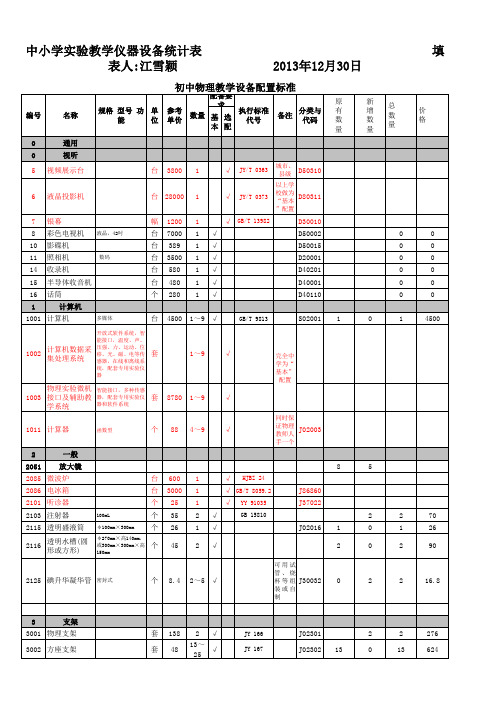
中小学实验教学仪器设备统计表新
1 13 13 1
0 0 0 0
1 13 13 1
312 1924 936 89.6
0 J00706 J00707 13
1 0
1 13
88 241.8
12001 机械停表 12002 机械停钟
0.1s
块 块
88 64
0.1s
13~ 25 13~ 25
√ √
QB/T 1534
J01215
12003 电子停表 12004 电子停钟 12010 节拍器 12011 沙漏 12015 日晷 13 温度
JY 0128
J00612
21001 圆柱体组 21002 立方体组 21003 运动和力实验 器
铜,铁,铝 铜,铁,铝, 木 材,不小于60cm3 长、短斜面,小车, 小球2个,硬盒,毛 巾,布
套 套 套 套 套
14.2 73.4 115 26.6 12.7 13.8 37 27 45 19.6 56 40.6 86 15
2 √ 25~ √ 50 2 √ 2 2 2 1 1 3 3 1 1 25~ √ 50 25~ √ 50 13~ √ 25 1 √ 3 3 1 1 √ √ √ √ √ √ √ √ √ √ √
JY 0127 JY 0127
直流电压、电流,检 流;2.5级 直流电压、电流,检 流;四位半 单相 500V
J01410 J01460 J01461 J01465 J14471 0 0 0 0
1 3 3 1 1
1 3 3 1 1
2.5级,0.6A,3A 2.5级,3V,15V ±300μ A 屏幕对角线不小于25 英寸
只 只 只 台
16001 密度计 16002 密度计 16004 湿度计 16005 罗盘 16008 空盒气压计 2 21 专用仪器 力学
可视对讲系统产品检验标准

一.可视对讲系统产品检验保准1目的和范围1.1 目的本标准提供本公司产品生产过程中的焊接、插件及组装工艺目视检验及测试验收的通用标准。
为公司产品提供验收依据。
1.2 应用范围本标准适用本公司产品的生产自检和品质检验的验收活动;本标准只适用于可视对讲系统的产品生产自检和品质检验的验收活动。
抽样检验:一般检验水平II级, AQL Cr:0,MA : 1,MI , 2.52参考文件IPC-A-610C (电子组装件的验收条件)GB2828.1-2003 (逐批计数抽样检验程序)GA/T 269-2001 (黑白可视对讲系统行业标准)Q/QDF 101-2000 (德康姆电子企业标准-可视对讲门铃)3定义3.1致命缺陷(Gr.):会给使用者安全、对产品或材料造成致命性功能障碍等的缺陷,如:材料的燃烧、冒烟、电击或爆炸,外毛刺刮伤等。
3.2主要缺陷(Ma.):凡物料的性能参数、尺寸大小、结构和材质不完全符合该材料规格要求,使产品有关功能特性或可靠性不能满足或可能降低,以及不能满足产品的外观缺陷标准。
3.3次要缺陷(Mi.):不会影响到产品功能特性正常生产装配的轻微缺陷。
3.4异常正常生产中同一部良现象超过2%或首次生产中同一不良现象连续三次出现称为产品异常4. 检验方法4.1 PCBA外观——目检,视力:1.0以上(含矫正视力);亮度:正常使用的环境亮度或40W日光灯下;目检距离:非特殊要求,按40±10cm,视角90度±12度;4.2 单快PCBA板上有两个和两个以上的MI.缺陷一MA或Cr缺陷即判定为不良。
4.3 电性能检测采用相应工装、设备和附件配合进行。
4.4 电性能检测所使用的工装、设备需校准和点检并合格或经客户提供确认后方可使用。
5. 检验标准序号缺陷缺陷定义分类方法工具PCBA1 缺件应有的元件未贴或插入PCB印制板Ma 目检2 多件不应有的元件贴或插入PCB印制板Ma 目检3 反向有方向性元件贴或插反(电容反向未Cr)Cr/Ma 目检4 错件元件种类或规格错误Ma 目检5 刮伤、破损元件表面刮伤、破损致使露出元件本体Ma 目检6 立碑片式元件末端翘起Ma 目检7 翘脚元件的一个或多个引脚变形,不能与焊盘正常接触Ma 目检8 脱皮表皮脱或缩落,改变原样(如:电容平顶)Ma 目检9 脱足元件脚未插入PCB板或未贴入焊盘Ma 目检10 错位元件脚贴或插错位置Ma 目检11 氧化元件脚、本体氧化或生锈Ma 目检12 浮高所有元器件原则上要求均需与PCB板平贴或压至最底部,且不影响下工序的装配;单允许有1.2mm浮高;特殊情况请参照样本Mi目检/塞规13 标识不清元件规格标识不清,无法辨认Ma 目检14 变形元件被挤迫、重压,导致变形,且影响电性能;因制程因素导致板材弯曲变形超过千分之八,且影响下工序的作业Ma 目检15 烫伤被烙铁或发热体烫伤露出本体,且影响电性能Ma 目检16 溢锡PCB板出现大量多余锡料Cr 目检17 倾斜直立元件与PCB板不垂直,倾斜>8度目检18 沾锡元件本体沾锡或锡渣目检19 标识软件等版本标识破损、错误目检20 跳脚IC或其他元件脚错位目检21 偏移不可超出焊盘的1/3或其他元件脚宽度的1/4目检22 烫伤PCB过炉太久而致使板变色目检23 翘皮PCB铜箔线路翘皮不许>圆周的5%或断路目检24 沾锡PCB板面沾锡珠(可视觉出)残留流锡,锡珠导致断路目检25 绿油起泡在导体区不允许出现在飞导体区的起泡不许超过1平方毫米目检26 刮伤PCB刮伤3mm以上,绿油脱落。
检验批容量汇编表

件
原始记录可注明不同类别构件数量
【压型金属板工程】01020410_压型金属板检验批?
件
【防腐涂料涂装】01020411_防腐涂料涂装检验批?
件
【防火涂料涂装】01020412_防火涂料涂装检验批?
件
【钢管混凝土结构基础】01020501_钢管构件进场验收检验批?
02030102_焊钉(栓钉)焊接工程检验批?
件
原始记录可注明不同类别构件数量
02030201_紧固件连接检验批?
件
原始记录可注明不同类别构件数量
02030202_高强度螺栓连接检验批?
处
指连接节点数量。原始记录可注明高强螺栓总个数、箱数
02030301_钢零部件加工检验批?
个
零部件种类较多,原始记录可分别注明数量
02010102_模板拆除检验批?
件或m2
02010201_钢筋原材料检验批?
t或批(种)
批(种)为每次进场钢筋所含牌号、规格数量,每批钢筋至少取样复试1组
02010202_钢筋加工检验批?
t或件或批(种)
件为成型钢筋的数量。每台加工机械每工作班加工的同一类型的成型钢筋为1批(种)
02010203_钢筋连接检验批?
根
【沉管灌注桩基础】01021101_混凝土灌注桩(钢筋笼)检验批?
根
【沉管灌注桩基础】01021102_混凝土灌注桩检验批?
根
【钢桩基础】01021201_钢桩(成品)检验批?
根
【钢桩基础】01021202_钢桩检验批?
根
01021301_锚杆静压桩基础检验批?
根
ISO898.1-2009中文

ISO898.1-2009中文ISO 898-1:2009(ISO第四次修订)二〇〇九年四月一日Mechanical properties of fasteners made of carbon steel and alloy steel—Part 1: Bolts, screws and studs with specified- property classes Coarse thread and fine pitch thread碳钢和合金钢紧固件机械性能第一部份螺栓、螺钉和螺柱粗牙和细牙系列(译文)目录前言…………………………………………………………………………………………1 范围………………………………………………………………………………………….2 引用标准…………………………………………………………………………………….3 术语和定义………………………………………………………………………………….4 代号和单位………………………………………………………………………………….5 性能等级的标记制度………………………………………………………………………..6 材料…………………………………………………………………………………………..7 机械性能和物理性能………………………………………………………………………..8 试验方法的适用性………………………………………………………………………….8.1 总则………………………………………………………………………………………..8.2 紧固件的承载能力………………………………………………………………………..8.3 制造者的控制……………………………………………………………………………….. 8.4 供应方的控制………………………………………………………………………………. 8.5 需求方的控制………………………………………………………………………………..8.6 实物紧固件和机加工试样可实施的相应试验系列………………………………………..9 试验方法………………………………………………………………………………………..9.1 螺栓和螺钉(不含螺柱)实物的楔负载试验………………………………………………9.2 螺栓、螺钉和螺柱的抗拉强度测定,R m……………………………………………………9.3 螺栓、螺钉和螺柱实物拉伸实验时测定断后伸长,A f和0.0048d非比例伸长应力,R pf……9.4 因头部强度弱,而不断在未旋合螺纹长度内的螺钉拉力试验………………………………9.5 腰状杆紧固件的拉力试验……………………………………………………………………9.6 螺栓、螺钉和螺柱的保证载荷试验…………………………………………………………9.7 机械加工试样的拉力试验……………………………………………………………………9.8 头部坚固性试验………………………………………………………………………………9.9 硬度试验………………………………………………………………………………………..9.10 脱碳试验……………………………………………………………………………………9.11 渗碳试验……………………………………………………………………………………9.12 再回火试验…………………………………………………………………………………9.13 扭矩试验…………………………………………………………………………………….9.14 机加工试样的冲击试验……………………………………………………………………..9.15 表面缺陷检查……………………………………………………………………………….10 标记……………………………………………………………………………………………10.1 总则…………………………………………………………………………………………10.2 制造者的识别标志………………………………………………………………………..10.3 紧固件承载能力的名称和标记…………………………………………………………. 10.4 因几何形状而降低了承载能力的紧固件的名称和标记………………………………. 10.5 包装标识……………………………………………………………………………………附录A抗拉强度和断后伸长率的关系………………………………………………………..附录 B 高温对紧固件力学性能的影响…………………………………………………………. 附录C 全尺寸紧固件的断后伸长率,A f……………………………………………………….. 引用文献1 范围本ISO898标准规定由碳钢和合金钢制造的,在环境温度为10℃~35℃条件下进行试验的螺栓、螺钉和螺栓的机械和物理性能。
- 1、下载文档前请自行甄别文档内容的完整性,平台不提供额外的编辑、内容补充、找答案等附加服务。
- 2、"仅部分预览"的文档,不可在线预览部分如存在完整性等问题,可反馈申请退款(可完整预览的文档不适用该条件!)。
- 3、如文档侵犯您的权益,请联系客服反馈,我们会尽快为您处理(人工客服工作时间:9:00-18:30)。
危害因素辨识案例分析2.1危险、危害因素的分类方法一:按GB/T13816-1992《生产过程危险和危害因素分类与代码》的规定,将生产过程中的危险.危害因素分为六类。
物理性危险.危害因素化学性危险.危害因素生物性危险.危害因素心理生理性危险危害因素行为性危险危害因素其他危险危害因素2.1.1物理性危险、危害因素1.设备.设施缺陷2.防护缺陷3.电危害4.噪声危害5.振动危害6.电磁辐射7.运动物危害8.明火9.能造成灼伤的高温物质10.能造成冻伤的低温物质11.粉尘与气溶胶12.作业环境不良13.信号缺陷14.标志缺陷15.其他物理性危险和危害因素2.1.2化学性危险、危害因素易燃易爆性物质自燃性物质有毒物质腐蚀性物质其他化学性危险.危害因素2.1.3生物性危险、危害因素致病微生物传染病媒介物致害动物致害植物其他生物性危险.危害因素2.1.4心理.生理性危险、危害因素负荷超限健康状况异常从事禁忌作业心理异常辨识功能缺陷其他心理.生理性危险危害因素2.1.5行为性危险、危害因素指挥错误操作失误监护失误其他错误其他行为性危险和有害因素2.1.6其他危险、危害因素方法二:参照事故类别和职业病类别进行分类参照GB6441-86《企业职工伤亡事故分类》,将危险.危害因素分为20类1.物体打击2.车辆伤害3.机械伤害4.起重伤害5.触电6.淹溺7.灼烫8.火灾9.高处坠落10.坍塌11.冒顶片帮12.透水13.放炮14.瓦斯爆炸15.火药爆炸16.锅炉爆炸17.容器爆炸18.其他爆炸19.中毒和窒息20.其他伤害考点分析:注意标准名称.代号——标准名称:《生产过程危险和危害因素分类与代码》——代号:GB/T13816-1992《企业伤亡事故分类》GB6441-86注意有哪些容易混淆的名称和标准号!考点分析:分类依据.共几类.哪些类型.危险危害因素的类属——分类依据:导致事故的原因——分类及类型:6大类:物理.化学.生物.心理生理.行为.其他——危险危害因素的类属:给出某一个危险因素,要求判断属于哪一类依据:起因物、引发事故的诱导性原因、致害物、伤害方式等20类考点分析:各类事故界定的范围,容易出错的几种事故分类重点注意以下9类(安全管理P77)物体打击:不包括因机械设备、车辆、起重机械、坍塌等引发的事故车辆伤害:不包括起重设备提升、牵引车辆和车辆停驶时发生的事故机械伤害:不包括车辆.起重机械引起的机械伤害起重伤害:起重作业发生的挤压、坠落、物体打击和触电触电:包括雷击伤亡事故淹溺:不包括矿山、井下淹溺灼烫:不包括电灼伤和火灾引起的烧伤高处坠落:不包括触电坠落事故坍塌:不适用于矿山冒顶片帮和车辆、起重机械、爆破引起的坍塌考点分析:典型场所.作业活动中存在的危险因素或危害因素——典型作业场所:危险化学品生产.经营.使用.运输场所;矿山;机械;人员密集场所;冶金;轻工;仓储等——典型作业活动:焊接.高处作业.有限或密闭空间.吊装.检修.机加工等特种作业或危险作业等——典型设备设施:特种设备.带电.加工.机动车辆等危险设备;重大危险源等例题1:某市罐瓶厂,有400m3液化石油气球罐3台,50m3液化石油气卧式贮罐2台,一条15kg罐装流水线,一条50kg罐装流水线,一条24称位手工罐装线。
主要公用和辅助设施有变配电站.锅炉房和空压站。
变配电站电压等级为25KV,内设5台变压器。
锅炉房内设2台4t/h燃煤锅炉,空压站安装有4台供气量为20m3/min的空气压缩机。
某日,该厂在充装过程中球罐焊缝处突然破裂,遇到明火引燃,在6万平方米的范围内立即形成一片火海。
由于火势太猛,邻近的1号球罐在大火烘烤4个多小时后,严重超压发生强烈爆炸,4块10多吨重的球壳碎片飞出100多米,事故造成死亡32人,伤54人。
1.按照《生产过程危险和有害因素分类与代码》的规定,在该企业的危险有害因素中,由物理性危险.有害因素造成事故包括()。
A.锅炉爆炸B.电气伤害C.火灾.爆炸D.中毒.窒息E.锅炉爆炸.电气伤害.中毒.窒息【答疑编号911010101】【答案】AB2.按照《生产过程危险和有害因素分类与代码》的规定,在该企业的危险.有害因素中,由化学性危险有害因素造成的事故包括()。
A.球罐内气体泄露引发的爆炸B.空压机气罐爆炸C.中毒和窒息D.设备缺陷E.火灾【答疑编号911010102】【答案】ACE案例2:某建筑公司承包了某居民楼的建设任务。
在建筑场地内有塔式起重机.及龙门架,混凝土搅拌机.机动翻斗车.电焊机等设备。
某日气温很高,工人甲.乙.丙.丁四人因天气热,将安全帽放在一边,在6层两阳台中间临时搭设的毛竹脚手架上作业,由于没有搭设卸料平台,调运上来的物料只好卸在该脚手架上的跳板上。
当第三车物料运上来时,工人甲进入跳板清理物料时,脚手架右侧内立杆突然断裂,跳板滑落,工人甲随之坠落,跳板砸在地面作业的2名工人头上,因未戴安全帽,当场死亡。
问题:根据《企业职工伤亡事故分类标准》,叙述塔式起重机.电焊机及翻斗车等设备可能出现的事故。
【答疑编号911010103】【参考答案】起重机事故类型:起重伤害(3分)电焊机事故类型:火灾.爆炸.触电(3分)机动翻斗车:车辆伤害(1分)2.2各类危险有害因素的辨识2.2.1危害辨识的主要内容(P78)为防止危害辨识出现漏项,可从企业生产管理系统中以下8个方面进行排查工作:1.厂址2.厂区平面布局3.道路及运输4.建(构)筑物5.生产工艺过程6.生产设备.装置7.作业环境8.安全管理措施厂址——厂址的工程地质、地貌、水文、气象条件、周围环境、交通运输条件、自然灾害、消防支持等。
道路及运输——从运输.装卸、疏散、消防、人流、物流、平面交叉运输和竖向交叉运输等方面分析厂区平面布局——考虑功能分区、防火间距、风向、建筑物朝向、危险有害物质设施、动力设施、道路、贮运设施等建(构)筑物厂房:生产火灾危险性分类、耐火等级、结构.层数、占地面积、防火间距.安全疏散等方面识别库房:储存物品的火灾危险性分类、耐火等级、结构、.层数、占地面积.防火间距.安全疏散等方面识别生产工艺过程(1)对新.改.扩建项目:设计是否合理是否根据需要采取了消除、预防、减少、隔离、连锁、安全警示标志等措施(2)对在线项目:主要根据行业和专业的特点,利用各行业和专业制定的安全标准.规程进行分析.识别(3)典型单元过程(基本单位.基本过程):主要通过查阅相关手册.规范.规程和规定生产设备.装置(1)对工艺设备:重点关注:高温、低温、高压、腐蚀、振动、关键部位的备用设备、控制.操作、检修和故障、失误时的紧急异常情况等方面分析(2)对电气设备:重点关注:触电、断电、火灾、爆炸、误运转和误操作、静电、雷电等方面分析(3)对机械设备:重点关注:运动零部件和工件、操作条件、检修作业、误运转和误操作等方面分析作业环境——重点考虑毒物、噪声、振动、高温低温、辐射、粉尘及其他有害因素安全管理措施——从组织机构、管理制度、应急预案、作业许可、安全监管等方面案例3:某家具厂危险有害因素辨识及事故防范措施A家具生产公司,决定选择新址建造新的家具加工基地。
考虑到城市规划、企业生产、销售及成本方面的需要,公司决定选择既方便运输又方便物料存放的一开阔地作为新厂址。
公司的具体论证方案如下:1.公司地址。
A公司地处某市开发区,与某精细涂料有限公司相邻,A公司以10km的地方有一家生产甲醇的化工公司,该公司生产的甲醇主要通过A公司西侧相邻码头外运,之间通过铁路专线运输。
为节省资金,A公司与精细涂料有限公司共同租赁了M公司的仓库,A公司租用3000 m2,用于储存材料和产品,精细涂料有限公司租用500m2,租赁仓库归使用方管理。
A公司生产的家具远销全国各地,全部通过汽车运输,由公司选定的通过OSHMS认证的运输商承运。
2.公司的主要机械包括电刨、电钻、电锯、小型轮式起重机、叉车、运输车辆等。
3.主要的生产过程包括材料运输和装卸、木材烘干、型材加工、组装、喷漆等。
1.如果让你对该论证方案进行危险有害因素辨识,按照《企业职工伤亡事故分类标准》(GB 6441-1986)的事故分类,指出主要的危险因素及产生部位。
【答疑编号911010201】参考答案:(1)机械伤害。
木材加工过程中使用电刨、电钻、电锯等的刨刃、锯齿及旋转部位的伤害,机械检修过程的各种伤害,加工件造成的伤害等。
(2)触电。
电刨、电钻、电锯的漏电触电,电动机械维修时误操作触电等。
(3)物体打击。
加工件飞出造成的打击伤害等。
(4)起重伤害。
起重过程中由于起重机故障、人员操作造成的起重伤害。
(5)火灾。
木材、油漆等造成的火灾伤害,甲醇铁路运输事故引发火灾。
(6)中毒和窒息。
油漆、黏合剂等的挥发。
(7)车辆伤害。
叉车、运输车辆等造成的车辆伤害。
(8)其他爆炸。
油漆等遇火源爆炸,甲醇铁路运输事故引发爆炸。
2.按照《企业职工伤亡事故分类标准》(GB 6441-1986)的事故分类,指出喷漆车间可能发生的主要事故。
为避免这些事故的发生,请列举主要的防范措施有哪些。
【答疑编号911010202】参考答案:主要事故包括:触电、火灾、其他爆炸、中毒和窒息等。
主要防范措施包括:加强电气检修,预防漏电,保证接地良好;控制火源,禁止出现明火、电器设备电路破损老化漏电打火、使用非防爆电器,完善消除静电的各项措施,防止静电火花;降低作业空间油漆和其他可燃物质浓度,保证通风措施完好并正常使用;保证个体防护设施、用品完备,具有各项完备的安全操作规程及管理制度。
3.按照《企业职工伤亡事故分类标准》(GB 6441-1986),下列()事故类别属于该分类标准。
A.火药爆炸B.瓦斯、煤尘爆炸C.锅炉爆炸D.煤尘爆炸提示:参见《企业职工伤亡事故分类标准》(GB 6441-1986)【答疑编号911010203】【答案】A、C2.2.2 危害辨识的方法(安全生产管理知识P78)直观经验法事件树(ETA)事故树(FTA)……对照、经验法类比方法系统安全分析方法2.2.3 重大危险源的辨识与管理——(安全管理P98,226)考点分析:1.重大危险源的判定方法:列表给出危险物品的现场量和临界值,进行计算;2.重大危险源的预防和管理技术:“3E”措施3.典型危险物品的临界值辨识或确认高危险的工业设施(重大危险源)——依据物质毒性、燃烧、爆炸特性,制定出危害物质及其临界量标准。
— GB18218-2000《重大危险源辨识》——通过危害物质及其临界量标准可以确定哪些是可能发生重大事故的潜在危险源。
重大危险源辨识标准——GB18218-2000《重大危险源辨识》生产场所重大危险源贮存区重大危险源两种爆炸性物质(26种)易燃物质(34种)活性化学物质(21种)有毒物质(61种)——列举142种物质的临界量标准适用于危险物质的生产、使用、贮存和经营等各企业或组织重大危险源管理2.2.4 典型场所危害有害因素的辨识机械、电气(《安全生产技术》P4、29)物体打击车辆伤害起重伤害触电灼烫火灾爆炸……触电火灾灼烫……特种设备(P141-150)锅炉:爆炸、起重机械:起重伤害(挤压、坍塌、物体打击、触电、高处坠落)压力容器:爆炸、高处坠落……烟花爆竹、民爆器材(P93)火灾爆炸触电机械伤害……交通运输(P141-150)道路交通:车辆伤害、火灾爆炸(P203)水上交通:碰撞、搁浅、触礁、沉没、火灾爆炸(P212)铁路交通:机车脱轨、机车车辆伤害、接触网触电、施工事故(P202)矿山(P222)爆炸(瓦斯、火药、粉尘)火灾水灾提升事故顶板垮塌冲击地压尾矿库溃坝建筑施工(P262)高处坠落触电物体打击机械伤害坍塌火灾……危险化学品(P313、343)火灾爆炸中毒腐蚀辐射……2.3 各类危险有害因素的相应控制措施2.3.1事故预防对策事故预防措施的选择的基本方法——3E措施EngineeringEducationEnforce2.3.2 安全技术对策防止事故发生的安全技术;1.消除危险源2.限制能量或危险物质3.隔离避免或减少事故损失的安全技术;1.隔离:远离、封闭、缓冲2.个体防护3.薄弱环节4.避难与援救采取措施减少故障的发生;1.安全系数2.提高可靠性3.安全监控系统按行业分:安全技术措施可分为:机械安全技术;防火防爆安全技术——(烟花爆竹、民爆器材、危险化学品等)冶金安全技术;交通运输安全技术;矿山安全技术;建筑施工安全技术;化工安全技术;职业危害防治技术……管理对策(enforce)安全生产责任制及其落实;安全操作规程及其执行;风险控制措施的制定与实施、隐患整改;安全培训教育安全检查、事故处理等;对设备、设施、装置、工具等检查、维修管理等;职工健康监护等。