G1MMH.3203P32中文资料
MM3280H01NRH_Specifications(中文) 2009.04.07
SYMBOL Division code
RoHS
(Compliance) G
ห้องสมุดไป่ตู้
輸出管制品 / EXPORT CONTROL
(Not Compliance) N 判定結果 Y or N
R
59 D232
MITSUMI ELECTRIC CO., LTD.
( 2 / 17 )
4. 概要 Outline
・ MM3280系列是采用高耐压CMOS制造工艺,对于2次用锂电池/聚合物电池在过充电,过放电及放电过电流时能起到保护作 用的IC。当单节锂电池/聚合物电池在发生过充电,过放电以及放电过电流现象时起到一定的保护作用。IC的内部由3个电压 检测器,短路检测电路,基准电压源,振荡电路,计数器电路,逻辑电路等构成。)
30 50 100 kΩ F
release resistance
DS端子下拉电阻 DS pin pull-down resistance
Rds VDD=0V
7.5 15.0 30.0 kΩ H
COUT Nch ON电圧 COUT pin Nch ON voltage
Vol1 Iol=30uA, VDD=4.5V -
V
-40 ~ +85
℃
-55 ~ +125
℃
9. 电气特性
Electrical characteristics
Topr=25℃
項目 Parameter
记号 Symbol
条件 Conditions
最小 标准 最大 单位 *1 Min. Typ. Max. Unit
工作电圧 Operating input voltage
给DS端子施加高电平(VDD电压),可以缩短各延时时间(短路检测延时时间除外),过充电检测延时时间可缩短到约2ms. 这样可以缩短保护板在生产测试时的时间。 Moreover, the delay time other than the short detection can be shortened by making the DS terminal voltage to VDD level. The overcharge detection delay time becomes about 2.0ms. As a result, the test time of the protection module can be shortened. ・ 如果连接大电压的充电器时,IC的Cout端子将立即输出低电平。 If over voltage charger is connected, immediately COUT output becomes low level. ・ IC的输出方式为CMOS输出。 Output type is CMOS output.
ZFM32F030 系列 32 位微控制器数据手册说明书

ZFM32F030系列32位微控制器数据手册V1.02版本记录版本日期更改者描述V1.002021.11.01第一版V1.012022.03.18第二版V1.022022.05.25第三版目录1简介 (1)1.1概述 (1)1.2主要特点 (1)2管脚描述 (3)2.1TSSOP20封装管脚排布图 (3)2.2QFN32封装管脚排布图 (3)2.3管脚定义表 (4)2.4管脚对应外设表 (7)3系统框图 (9)4系统描述 (10)4.1ARM Cortex®-M0内核 (10)4.2内存映射 (11)4.3嵌套向量中断控制器(NVIC) (13)4.4系统复位 (14)4.5时钟控制 (14)4.6I/O复用配置 (15)5外设描述 (16)5.1GPIO(通用输入/输出接口) (16)5.2UART(通用异步收发器) (16)5.3I2C总线 (16)5.4SPI(串行外设接口) (16)5.5TIM(定时/计数器) (17)5.6PWM(脉冲宽度调制)模块 (17)5.7WDT(看门狗定时器) (17)5.8ADC(模拟/数字转换器) (17)5.9存储器 (18)5.10电源管理 (18)5.10.1睡眠模式 (18)5.10.2停止模式 (18)5.11SWD调试口 (19)6电气规范 (20)6.1绝对最大额定值 (20)6.2电特性表 (20)6.2.1MCU参数 (20)6.2.2BOD参数 (21)6.2.3ADC参数 (21)6.2.4Flash参数 (22)6.2.5SPI参数 (22)6.2.6I2C参数 (24)7封装尺寸 (25)7.1TSSOP20封装 (25)7.2QFN32封装 (26)1简介1.1概述ZFM32F030系列是内嵌ARM Cortex®-M0核的32位低成本通用微控制器。
最高频率可达48MHz,片内集成32KB Flash存储器,4KB SRAM存储器。
M25P32中文资料
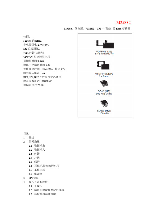
M25P3232Mbit,低电压,75MHZ,SPI串行接口的flash存储器特征:32Mbit的flash。
单电源供电2.7~3.6V。
SPI总线通讯。
75M时钟(最大)VPP=9V快速读写电压页操作时间0.6ms擦出一个扇区时间0.6s整块擦除时间:标准23s,快速17s睡眠模式电流1uABP0,BP1,BP2硬件写保护选择位擦写次数可达100000次数据可保存20年目录1描述2信号描述数据输出数据输入时钟片选保护写保护,提高编程电压工作电压电源地3SPI协议4操作方法和时序页操作扇区的擦除和整块的擦写写检测和循环擦除快速编程和擦除操作激活,正常工作,睡眠模式状态寄存器保护方法保持条件5存储组织结构6操作说明写操作使能使能复位读器件ID读状态寄存器WIP位WEL位BP2,BP1,BP0位SRWD位写状态寄存器读数据操作快速读数据操作页操作扇区擦除操作整个器件擦除睡眠模式激活器件78原始状态9极限参数10DC和AC参数11硬件结构12编号13修订记录1 描述M25P32是32Mbit(4M*8)的串行flash存储器,具有增强写保护结构。
存取采用SPI 总线协议。
一次性可编程1-256个字节(参考页编程操作说明)。
增强型快速编程、擦除模式可适用于需要快速存储的场合。
当V PPH 达到写保护或增强编程电压时即可进入此模式。
存储结构分为64个扇区,每个含有256页,每页256字节的宽度,所以整个器件可以看成有16384页组成(或者4194304个字节组成)整个器件的擦除(参考整块擦除说明),一次擦除一个扇区(参考扇区擦除说明)图1表1图22信号描述串行数据输出(Q)串行数据输入(D)图31.DU = Don’t use2.3 串行时钟信号2.4片选()当片选端输入为高时,那么取消选定器件,此时串行数据输出为高阻态,除非内部编程,循环对擦除、写寄存器进行操作,器件将工作在标准电源模式下(非睡眠模式)当器件片选信号拉低使能时,即器件进入正常工作模式。
MAX3232中文资料zhuanzai

MAX3222/MAX3232/MAX3237/MAX32413.0V至5.5V、低功耗、1Mbps、真RS-232收发器,使用四只0.1µF外部电容________________________________________________________________Maxim Integrated Products119-0273; Rev 7; 1/07MegaBaud和UCSP是Maxim Integrated Products, Inc.的商标。
本页已使用福昕阅读器进行编辑。
M A X 3222/M A X 3232/M A X 3237/M A X 32413.0V至5.5V、低功耗、1Mbps、真RS-232收发器,使用四只0.1µF外部电容2_______________________________________________________________________________________ABSOLUTE MAXIMUM RATINGSELECTRICAL CHARACTERISTICS(V CC = +3.0V to +5.5V, C1–C4 = 0.1µF (Note 2), T A = T MIN to T MAX , unless otherwise noted. Typical values are at T A = +25°C.)Stresses beyond those listed under “Absolute Maximum Ratings” may cause permanent damage to the device. These are stress ratings only, and functional operation of the device at these or any other conditions beyond those indicated in the operational sections of the specifications is not implied. Exposure to absolute maximum rating conditions for extended periods may affect device reliability.Note 1:V+ and V- can have a maximum magnitude of 7V, but their absolute difference cannot exceed 13V.V CC ...........................................................................-0.3V to +6V V+ (Note 1)...............................................................-0.3V to +7V V- (Note 1)................................................................+0.3V to -7V V+ + V- (Note 1)...................................................................+13V Input VoltagesT_IN, SHDN , EN ...................................................-0.3V to +6V MBAUD...................................................-0.3V to (V CC + 0.3V)R_IN.................................................................................±25V Output VoltagesT_OUT...........................................................................±13.2V R_OUT....................................................-0.3V to (V CC + 0.3V)Short-Circuit DurationT_OUT....................................................................ContinuousContinuous Power Dissipation (T A = +70°C)16-Pin TSSOP (derate 6.7mW/°C above +70°C).............533mW 16-Pin Narrow SO (derate 8.70mW/°C above +70°C)....696mW 16-Pin Wide SO (derate 9.52mW/°C above +70°C)........762mW 16-Pin Plastic DIP (derate 10.53mW/°C above +70°C)...842mW 18-Pin SO (derate 9.52mW/°C above +70°C)..............762mW 18-Pin Plastic DIP (derate 11.11mW/°C above +70°C)..889mW 20-Pin SSOP (derate 7.00mW/°C above +70°C).........559mW 20-Pin TSSOP (derate 8.0mW/°C above +70°C).............640mW 28-Pin TSSOP (derate 8.7mW/°C above +70°C).............696mW 28-Pin SSOP (derate 9.52mW/°C above +70°C).........762mW 28-Pin SO (derate 12.50mW/°C above +70°C).....................1W Operating Temperature RangesMAX32_ _C_ _.....................................................0°C to +70°C MAX32_ _E_ _ .................................................-40°C to +85°C Storage Temperature Range.............................-65°C to +150°C Lead Temperature (soldering, 10s).................................+300°CMAX3222/MAX3232/MAX3237/MAX32413.0V至5.5V、低功耗、1Mbps、真RS-232收发器,使用四只0.1µF外部电容_______________________________________________________________________________________3TIMING CHARACTERISTICS—MAX3222/MAX3232/MAX3241(V CC = +3.0V to +5.5V, C1–C4 = 0.1µF (Note 2), T A = T MIN to T MAX , unless otherwise noted. Typical values are at T A = +25°C.)ELECTRICAL CHARACTERISTICS (continued)(V CC = +3.0V to +5.5V, C1–C4 = 0.1µF (Note 2), T A = T MIN to T MAX , unless otherwise noted. Typical values are at T A = +25°C.)M A X 3222/M A X 3232/M A X 3237/M A X 32413.0V至5.5V、低功耗、1Mbps、真RS-232收发器,使用四只0.1µF外部电容4________________________________________________________________________________________________________________________________________________________________典型工作特性(V CC = +3.3V, 235kbps data rate, 0.1µF capacitors, all transmitters loaded with 3k Ω, T A = +25°C, unless otherwise noted.)-6-5-4-3-2-101234560MAX3222/MAX3232TRANSMITTER OUTPUT VOLTAGEvs. LOAD CAPACITANCELOAD CAPACITANCE (pF)T R A N S M I T T E R O U T P U T V O L T A G E (V )20003000100040005000246810121416182022150MAX3222/MAX3232SLEW RATEvs. LOAD CAPACITANCELOAD CAPACITANCE (pF)S L E W R A T E (V /µs )20003000100040005000510152025303540MAX3222/MAX3232SUPPLY CURRENT vs. LOAD CAPACITANCEWHEN TRANSMITTING DATALOAD CAPACITANCE (pF)S U P P L Y C U R R E N T (m A )20003000100040005000TIMING CHARACTERISTICS—MAX3237(V CC = +3.0V to +5.5V, C1–C4 = 0.1µF (Note 2), T A = T MIN to T MAX , unless otherwise noted. Typical values are at T A = +25°C.)Note 2:MAX3222/MAX3232/MAX3241: C1–C4 = 0.1µF tested at 3.3V ±10%; C1 = 0.047µF, C2–C4 = 0.33µF tested at 5.0V ±10%.MAX3237: C1–C4 = 0.1µF tested at 3.3V ±5%; C1–C4 = 0.22µF tested at 3.3V ±10%; C1 = 0.047µF, C2–C4 = 0.33µF tested at 5.0V ±10%.Note 3:Transmitter input hysteresis is typically 250mV.MAX3222/MAX3232/MAX3237/MAX32413.0V至5.5V、低功耗、1Mbps、真RS-232收发器,使用四只0.1µF外部电容_______________________________________________________________________________________5-7.5-5.0-2.502.55.07.50MAX3241TRANSMITTER OUTPUT VOLTAGEvs. LOAD CAPACITANCELOAD CAPACITANCE (pF)T R A N S M I T T E R O U T P U T V O L T A G E (V )2000300010004000500046810121416182022240MAX3241SLEW RATEvs. LOAD CAPACITANCELOAD CAPACITANCE (pF)S L E W R A T E (V /µs )20003000100040005000510152025303545400MAX3241SUPPLY CURRENT vs. LOADCAPACITANCE WHEN TRANSMITTING DATALOAD CAPACITANCE (pF)S U P P L Y C U R R E N T (m A )20003000100040005000-7.5-5.0-2.502.55.07.50MAX3237TRANSMITTER OUTPUT VOLTAGE vs. LOAD CAPACITANCE (MBAUD = GND)LOAD CAPACITANCE (pF)T R A N S M I T T E R O U T P U T V O L T A G E (V )200030001000400050000102030504060700MAX3237SLEW RATE vs. LOAD CAPACITANCE(MBAUD = V CC )LOAD CAPACITANCE (pF)S L E W R A T E (V /µs )500100015002000-7.5-5.0-2.502.55.07.50MAX3237TRANSMITTER OUTPUT VOLTAGE vs. LOAD CAPACITANCE (MBAUD = V CC )LOAD CAPACITANCE (pF)T R A N S M I T T E R O U T P U T V O L T A G E (V )5001000150020001020304050600MAX3237SUPPLY CURRENT vs.LOAD CAPACITANCE (MBAUD = GND)LOAD CAPACITANCE (pF)S U P P L Y C U R R E N T (m A )200030001000400050000246810120MAX3237SLEW RATE vs. LOAD CAPACITANCE(MBAUD = GND)LOAD CAPACITANCE (pF)S L E W R A T E (V /µs )2000300010004000500010302040506070MAX3237SKEW vs. LOAD CAPACITANCE(t PLH - t PHL )LOAD CAPACITANCE (pF)1000150050020002500____________________________________________________________________典型工作特性(续)(V CC = +3.3V, 235kbps data rate, 0.1µF capacitors, all transmitters loaded with 3k Ω, T A = +25°C, unless otherwise noted.)M A X 3222/M A X 3232/M A X 3237/M A X 32413.0V至5.5V、低功耗、1Mbps、真RS-232收发器,使用四只0.1µF外部电容6_________________________________________________________________________________________________________________________________________________________________引脚说明MAX3222/MAX3232/MAX3237/MAX32413.0V至5.5V、低功耗、1Mbps、真RS-232收发器,使用四只0.1µF外部电容_______________________________________________________________________________________7_______________________________详细说明双电荷泵电压转换器MAX3222/MAX3232/MAX3237/MAX3241的内部电源由两路稳压型电荷泵组成,只要输入电压(V CC )在3.0V至5.5V范围以内,即可提供+5.5V (倍压电荷泵)和-5.5V (反相电荷泵)输出电压。
MAQ3203YM;中文规格书,Datasheet资料

MAQ3203High-Brightness LED Driver Controllerwith High-Side Current SenseGeneral DescriptionThe MAQ3203 is a hysteretic, step-down, constant-current, High-Brightness LED (HB LED) driver. It provides an ideal solution for interior/exterior lighting, architectural and ambient lighting, LED bulbs, and other general illumination applications.The MAQ3203 is well suited for lighting applications requiring a wide-input voltage range. The hysteretic control gives good supply rejection and fast response during load transients and PWM dimming. The high-side current sensing and on-chip current-sense amplifier delivers LED current with ±5% accuracy. An external high-side current-sense resistor is used to set the output current.The MAQ3203 offers a dedicated PWM input (DIM) which enables a wide range of pulsed dimming. A high-frequency switching operation up to 1.5MHz allows the use of smaller external components minimizing space and cost. The MAQ3203 offers frequency dither feature for EMI control. The MAQ3203 operates over a junction temperature from −40°C to +125°C and is available in an 8-pin SOIC package. The MAQ3203 is AEC-Q100 qualified for automotive applications.Datasheets and support documentation can be found on Micrel’s web site at: .Features• AEC-Q100 qualified• 4.5V to 42V input voltage range • High efficiency (>90%) • ±5% LED current accuracy • Dither enabled for low EMI • High-side current sense• Dedicated dimming control input• Hysteretic control (no compensation!) • Up to 1.5MHz switching frequency • Adjustable constant LED current • Over-temperature protection• −40°C to +125°C junction temperature rangeApplications• Automotive lighting • Industrial lighting_________________________________________________________________________________________________________________________Typical ApplicationMAQ3203 Step-down LED DriverOrdering Information (1)Part NumberMarking Junction Temperature Range PackagePWM MAQ3203YM MAQ3203YM −40°C to +125°C8-Pin SOICDitherNote:1. YM ®is a GREEN RoHS compliant package. Lead finish is NiPdAu. Mold compound is Halogen Free.Pin Configuration8-Pin SOIC MAQ3203Pin DescriptionPin NumberPin NamePin Function1 VCCVoltage Regulator Output. The V CC pin supplies the power to the internal circuitry. The VCC in the output of a linear regulator which is powered from VIN. A 1µF ceramic capacitor is recommended for bypassingand should be placed as close as possible to the VCC and AGND pins. Do not connect to an external load. 2 CSCurrent-Sense Input. The CS pin provides the high-side current sense to set the LED current with anexternal sense resistor. 3 VINInput Power Supply. VIN is the input supply pin to the internal circuitry and the positive input to the current sense comparator. Due to the high frequency switching noise, a 10µF ceramic capacitor isrecommended to be placed as close as possible to VIN and the power ground (PGND) pin for bypassing. Please refer to layout recommendations. 4AGNDGround pin for analog circuitry. Internal signal ground for all low power sections.5 ENEnable Input. The EN pin provides a logic level control of the output and the voltage has to be 2.0V or higher to enable the current regulator. The output stage is gated by the DIM pin. When the EN pin is pulled low, the regulator goes to off state and the supply current of the device is greatly reduced (below 1µA). In the off state, during this period the output drive is placed in a "tri-stated" condition, where MOSFET is in an “off” or non-conducting state. Do not drive the EN pin above the supply voltage. 6 DIM PWM Dimming Input. The DIM pin provides the control for brightness of the LED. A PWM input can beused to control the brightness of LED. DIM high enables the output and its voltage has to be at least2.0V or higher. DIM low disables the output, regardless of EN “high” state. 7 PGND Power Ground Pin for Power FET. Power Ground (PGND) is for the high-current switching withhysteretic mode. The current loop for the power ground should be as small as possible and separatefrom the Analog ground (AGND) loop. Refer to the layout considerations for more details. 8 DRVGate-Drive Output. Connect to the gate of an external N-channel MOSFET. The drain of the external MOSFET connects directly to the inductor and provides the switching current necessary to operate inhysteretic mode. Due to the high frequency switching and high voltage associated with this pin, the switch node should be routed away from sensitive nodes.Absolute Maximum Ratings (1)V IN to PGND..................................................−0.3V to +45V V CC to PGND................................................−0.3V to +6.0V CS to PGND........................................−0.3V to (V IN+ 0.3V) EN to AGND........................................−0.3V to (V IN+ 0.3V) DIM to AGND......................................−0.3V to (V IN+ 0.3V) DRV to PGND....................................−0.3V to (V CC+ 0.3V) PGND to AGND..........................................−0.3V to + 0.3V Junction Temperature................................................150°C Storage Temperature Range....................−60°C to +150°C Lead Temperature (Soldering, 10sec).......................260°C ESD Ratings (3)HBM......................................................................1.5kV MM.........................................................................200V Operating Ratings (2)Supply Voltage (V IN)..........................................4.5V to 42V Enable Voltage (V EN)..............................................0V to V IN Dimming Voltage (V DIM).................................................................0V to V IN Junction Temperature (T J)........................−40°C to +125°C Junction Thermal ResistanceSOIC(θJA).......................................................98.9°C/W SOIC(θJC).......................................................48.8°C/WElectrical Characteristics (4)V IN = V EN = V DIM = 12V; C VCC = 1.0µF; T J = 25°C, bold values indicate −40°C ≤ T A≤+125°C; unless noted.Symbol Parameter Condition Min. Typ. Max. Units Input SupplyV IN Input Voltage Range (V IN) 4.5 42 VI S Supply Current DRV = open 1 3 mAI SD ShutdownCurrent V EN = 0V 1 µA UVLO V IN UVLO Threshold V IN rinsing 3.2 4 4.5 VUVLO HYS V IN UVLO Hysteresis 500 mVVCC SupplyVCC V CC Output Voltage V IN = 12V, I CC = 10mA 4.5 5 5.5 V Current Limit201.4 212 222.6 mV V CS(MAX)Current Sense Upper Threshold V CS(MAX )= V IN− V CS199 212 225 mV168 177 186 mV V CS(MIN)Sense Voltage Threshold Low V CS(MIN )= V IN− V CS165 177 189 mVV CSHYS V CS Hysteresis 35 mVV CS Rising 50 ns Current Sense Response TimeV CS Falling 70 ns CS Input Current V IN− V CS = 220mV 0.5 10 µA FrequencyF MAX SwitchingFrequency 1.5MHz Dithering (MAQ3203)V DITH V CS Hysteresis Dithering Range(5) ±6 mVF DITHER FrequencyDitheringRange(5)% of Switching Frequency ±12 %Electrical Characteristics (4) (Continued)V IN = V EN = V DIM = 12V; C VCC = 1.0µF; T J = 25°C, bold values indicate −40°C ≤ T J≤+125°C; unless noted.Symbol Parameter Condition Min. Typ. Max. Units Enable InputEN HI EN Logic Level High 2.0 VEN LO EN Logic Level Low 0.4 VV EN = 12V 60 µA EN Bias CurrentV EN = 0V 1 µAStart-UpTime From EN Pin going high to DRVgoing high30 µsDimming InputDIM HI DIM Logic Level High 2.0 V DIM LO DIM Logic Level Low 0.4 V20 50DIM Bias CurrentV DIM = 0V 1µADIM Delay Time From DIM Pin going high to DRVgoing high450 nsF DIM Maximum Dimming Frequency 20 kHz External FET DriverPull Up, I SOURCE = 10mA 2 DRVOn-ResistancePull Down, I SINK = -10mA 1.5ΩRise Time, C LOAD = 1000pF 13DRVTransitionTimeFall Time, C LOAD = 1000pF 7ns Thermal ProtectionT LIM Over-TemperatureShutdown T J Rising 160T LIMHYS Over-TemperatureShutdownHysteresis 20°C Notes:1. Exceeding the absolute maximum rating may damage the device.2. The device is not guaranteed to function outside its operating rating.3. Devices are ESD sensitive. Handling precautions recommended. Human body model, 1.5k in series with 100pF.4. Specification for packaged product only.5. Guaranteed by design.Typical CharacteristicsFunctional CharacteristicsFunctional Characteristics (Continued)Functional DiagramFigure 1. MAQ3203 Block DiagramFunctional DescriptionThe MAQ3203 is a hysteretic step-down driver which regulates the LED current over wide input voltage range. The device operates from a 4.5V to 42V input MOSFET voltage range and provides up to 0.5A source and 1A sink drive capability. When the input voltage reaches 4.5V, the internal 5V VCC is regulated and the DRV pin is pulled high to turn on an external MOSFET if EN pin and DIM pin are high. The inductor current builds up linearly. When the CS pin voltage hits the V CS(MAX) with respect to V IN , the MOSFET turns off and the Schottky diode takes over and returns the current to V IN . Then the current through inductor and LEDs starts decreasing. When CS pin hits V CS(MIN), the MOSFET turns on and the cycle repeats.The frequency of operation depends upon input voltage, total LEDs voltage drop, LED current and temperature. The calculation for frequency of operation is given in application section.The MAQ3203 has an on board 5V regulator which is for internal use only. Connect a 1µF capacitor on VCC pin to analog ground.The MAQ3203 has an EN pin which gives the flexibility to enable and disable the output with logic high and low signals.The MAQ3203 also has a DIM pin which can turn on and off the LEDs if EN is in HIGH state. This DIM pin controls the brightness of the LED by varying the duty cycle of DIM pin from 1% to 99%.分销商库存信息: MICRELMAQ3203YM。
Hypertherm Powermax G3 Series Plasma Cutter 说明书

The performance standard for air plasma cuttingISO 9001S E R I ESG3™3⁄4"(19mm )1"(25mm )11⁄4"(32mm )Maximum capacitySeverance capacityRecommended capacityHypertherm – the world leader in plasma cutting technologyWhen you do only one thing, you’d better do it better than anyone else. As the only major manufacturer to focus exclusively on plasma cutting technology, Hypertherm is committed to providing the highest quality systems in the world: improving the performance, reliability and value of our systems, and serving and supporting Hypertherm users. This commitment to technology leadership, quality and support makes Hypertherm the first choice of the true cutting professional.Superior performance by hand or machineThe Powermax1000 is the latest addition to the Powermax G3 Series. With advanced technologies in both power supply and torch,The third generation of plasma cutting has a second great product!The power supply:the heart of the machineAdvanced, intelligent technology gives the Powermax1000 the power to cut with greater speed, quality and efficiency.60-amp, 8.4-kilowatt output provides ample power for clean, quick cutting.Auto-voltage runs on voltages from 200 to 600 volts, 1- or 3-phase, (CE 230 to 400 V 3-phase only) without the need for manual rewiring.New Boost Conditioner ™circuitcompensates for input voltage variation. Advanced, digitally-controlled inverter design delivers continuously adjustable, constant current output from 20 to 60 amps, permitting high-quality cuts over a wide range of metal thicknesses.An active electronic pilot arc controller for cutting expanded metal or grating. New gouging setting for easier operation and faster metal removal.CNC/robotic machine interface is standard on all units, allowing automated control and rapid changeover to mechanized operation.Hypertherm G3 products cut faster and more economically than any system available today.The Powermax1000’s Auto-voltage ™circuit provides automatic adjustment to any input voltage from 200 to 600 volts, 1- or 3-phase (CE 230 to 400 V 3-phase only). A state-of-the-art, microprocessor-based architecture assures optimum system reliability. Add to this Hypertherm’s advanced torch technology and easy-to-read controls, and you have the most advanced plasma cutter money can buy.Recommended capacity: metals to 3⁄4inch (19 mm) at cutting speeds over 20 inches (500 mm) per minute.Maximum capacity:metals to 1 inch (25 mm) at cutting speeds over 10 inches (250 mm) per minute.Severance capacity:rough cut on metals up to 11⁄4inches (32 mm) at low speed.The cut capacities above are on mild steel.Some metals, such as aluminum and stainless steel, may require up to 20% reduction in cut speed and capacity.Machine torch operationUp to 1⁄2inch (12 mm) Maximum capacity.Up to 3⁄8inch (10 mm) Recommended capacity.No breakable ceramic parts. withOperating cost calculations are based on consumable price, tested consumable life, tested cutting speed, estimated labor and power costs. Competitive units are in the 50 – 60 amp cutting range.Powermax1000Competitor ACompetitor BCompetitor CHypertherm, Powermax, G3 Series, HyLife, Boost Conditioner, Dual-threshold, Auto-voltage, Coaxial-assist, ETR (Easy Torch Removal) and FineCut are trademarks of Hypertherm, Inc. and may be registered in the United States and/or other countries.© Copyright 2/04 Hypertherm, Inc. Revision 2 860240 North AmericanHypertherm, Inc. ***********************************************************Hypertherm Automation, LLC **************************************************************Hypertherm Plasmatechnik, GmbH Deutschland 49 6181 58 2100 Tel 49 6181 58 2134 Fax *********************************Hypertherm (S) Pte Ltd ******************************************************************Hypertherm UK, Ltd *************************************************************France 0080033249737Té*********************************************Hypertherm S.r.l. ****************************************************************Hypertherm Europe B.V. Nederland 31 165 59 69 08 Tel 31 165 59 69 01 Fax ****************************Japan 8105 59757387 Tel 8105 59757376 Fax HT *************************Hypertherm Brasil Ltda. **********************************************************Input voltages 200 – 600 V, 1/3-PH, 50 - 60 Hz, CSA 230 – 400 V, 3-PH, 50 - 60 Hz, CEInput current @8.4 kW200/208/230/240/480 V, 1-PH: 50/48/44/42/22 A 200/208/230/240/400/480/600 V, 3-PH: 30/29/26/24/15/12/11 A Output voltage 140 VDCDuty cycle @ 40˚ C 50% @ 60 A, 230 – 600 V, 3-PH (104˚ F)50% @ 60 A, 230 – 480 V, 1-PH 40% @ 60 A, 200 – 208 V, 3-PH 40% @ 60 A, 200 – 208 V, 1-PH Maximum OCV 300 VDCDimensions 23.1" (586 mm) D; 10.7" (271 mm) W; 19.6" (498 mm) H Weight with torch 83 lbs (37 kg)Gas supply Clean, dry, oil-free air or nitrogenFlow rate 400 scfh; 6.7 cfm (189 l/min) at 90 psi (6.2 bar)Flow pressure70 psi (4.8 bar) flowing, 25' leads 75 psi (5.1 bar) flowing, 50' leadsPowermax1000 G3 Series standard system componentsPower supplyT60 or T60M torch Spare consumables Work cable with clamp 15 feet (4.5 m)Primary power cableOptions - (Part number)Circle cutting guide - 027668Wheel kit - 128646Leather cable covers - 024548Air filtration kit - 128647Extended work cable - 128717Hand heat shield - 128658Ordering informationSpecificationsMaximum Material Thickness Current travel speed*(inches)(mm)(amps)(ipm)(mm/min.)Mild steel26 GA.0.5256381620510 GA.3.44015138351⁄4 6.46013233533⁄810606316001⁄212604210675⁄81660317873⁄4196022559Aluminum1⁄320.825610154941⁄8 3.24020451821⁄4 6.46014536833⁄810607418801⁄212605112955⁄8166033838Stainless 26 GA.0.52563116027steel 14 GA.1.94022156131⁄4 6.46011027943⁄810605313461⁄21260358895⁄81660266603⁄4196018457*Maximum travel speeds are the results of Hypertherm's laboratory testing. For optimum cut performance, actual cutting speeds may vary based on different cutting applications. Refer to the operator's manual for more details.S IP23CSSystems part numbersWith 25' With 50' With 75'(7.5 m) torch(15 m) torch (23 m) torch200 – 600 V, 1/3-PH, CSA Hand system 083178083179083210Machine system083182083183083212230 – 400 V, 3-PH, CE Hand system 083192083193083211Machine system083194083195083213(where indicated)High-performance portable plasma cutting system。
UEP1C332MHD中文资料

(mm)
• Please refer to page 21 about the end seal configulation.
Configuration Pb-free leadwire fD Pb-free PET sleeve 5 DD 6.3 ED 8 á 10 PD 12.5 ~ 18 HD
63 0.12 63 2 3
100 0.10 100 2 3
Measurement frequency : 120Hz
Stability at Low Temperature
Rated voltage (V) Z– 25°C / Z+20°C Impedance ratio ZT / Z20 (MAX.) Z– 40°C / Z+20°C
Shelf Life Marking
After storing the capacitors under no load at 105°C for 1000 hours, and after performing voltage treatment based on JIS C 5101-4 clause 4.1 at 20°C, they will meet the specified value for endurance characteristics listed above. Printed with white color letter on black sleeve.
CAT.8100V
– 55 ~ +105°C 6.3 ~ 100V 0.47 ~ 6800µF ± 20% at 120Hz, 20°C After 5 minutes' application of rated voltage, leakage current is not more than 0.03CV or 3 (µA), whichever is greater.
EFM32 Giant Gecko Series 1 家庭产品系列数据表说明书
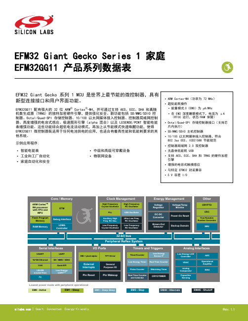
EFM32 Giant Gecko Series 1 家庭EFM32GG11 产品系列数据表EFM32 Giant Gecko 系列 1 MCU 是世界上最节能的微控制器,具有新型连接接口和用户界面功能。
EFM32GG11 配有强大的 32 位 ARM® Cortex®-M4,并可通过支持 AES、ECC、SHA 和真随机数生成器 (TRNG) 的独特加密硬件引擎,提供强化安全。
新功能包括 SD/MMC/SDIO 控制器、Octal/Quad-SPI 存储控制器、10/100 以太网媒体接入控制器、控制器局域网控制器、高度增强的电容式感应、极速图形引擎(alpha 混合)以及 LESENSE/PCNT 智能电能表增强功能。
这些功能结合超低电流活动模式,再加上从节能模式快速唤醒功能,使得EFM32GG11 微控制器既适用于任何电池供电的应用,也适合有着高性能和低能耗要求的其他系统。
示例应用程序:•ARM Cortex-M4(功率为 72 MHz)•超低能耗操作•能量模式0(EM0)为 µA/MHz•在 EM2 深度睡眠模式下,电流为 μA(RTCC 运行,状态/RAM 保留)•Octal/Quad-SPI 存储控制器接口(支持芯片内执行)•SD/MMC/SDIO 主机控制器•10/100 以太网媒体接入控制器,符合802.3az EEE、IEEE1588 节能规范•控制器局域网 2.0 双控制器•无晶体低能耗 USB•支持 AES、ECC、SHA 和 TRNG 的硬件加密引擎•增强的电容式触摸感应•与特定 EFM32 封装兼容•5 V 容差 I/O•智能电能表•工业和工厂自动化•家庭自动化和安全•中级和高级可穿戴设备•物联网设备1.功能列表EFM32GG11 重要功能如下所列。
•ARM Cortex-M4 CPU 平台•High performance 32-bit processor @ up to 72 MHz•DSP instruction support and Floating Point Unit•Memory Protection Unit•Wake-up Interrupt Controller•灵活能源管理系统•在活动模式下 (EM0),功耗为 μA/MHz•在 EM2 深度睡眠模式下,电流为 μA(16 kB RAM 保留,从LFRCO 运行 RTCC)•集成直流到直流降压转换器•高达 2048 kB 的闪存程序存储器•双组闪存,支持读写同步•高达 512 kB 的 RAM 数据存储•256 kB 纠错内存(SEC-DED 汉明码)•Octal/Quad-SPI 闪存存储接口•支持 3 V 和 1.8 V 内存•1/2/4/8 位数据总线•Quad-SPI 芯片内执行 (XIP)•通信接口•低能耗通用串行总线 (USB),可提供设备和主机支持•与 USB 2.0 完全兼容•片上物理层和 5V 至 3.3 V 嵌入式稳压器•无晶体设备模式操作•专利申请中的低能耗模式 (LEM)•SD/MMC/SDIO 主机控制器•SD v3.01、SDIO v3.0 和 MMC v4.51 高达 50 MHz•1/4/8 位总线宽度•10/100 以太网媒体接入控制器,带有 MII/RMII 接口•IEEE1588-2008 精密时间戳协议•节能以太网 (802.3az)•最多 2 个控制器局域网控制器• 2.0A 和 2.0B 版本速度高达 1 Mbps• 6 个通用同步/异步接收器/传输器•UART/SPI/SmartCard (ISO 7816)/IrDA/I2S/LIN•三重缓冲全双工/半双工操作,带有流控制•在一个实例上的超高速操作 (36 MHz)• 2 个通用异步接收器/传输器• 2 个低能耗 UART•在深度睡眠模式下,使用 DMA 进行自主操作• 3 个 I2C 接口(受 SMBus 支持)•EM3 停止模式下的地址识别•通用 I/O 引脚最高为 144•可配置的推挽、开漏、上拉/下拉、输入滤波器和驱动强度•可配置的外围设备 I/O 位置•特定引脚上的 5 V 电压耐受•异步外部中断•输出状态保留和从关机模式唤醒•多达 24 个信道 DMA 控制器•用于在外围设备之间自主传输信号的最多 24 个信道外围设备反射系统 (PRS)•外部总线接口,适用于最大为 4x256 MB 外部存储器映射空间•带有直接驱动功能的 TFT 控制器•alpha 混合像素引擎•硬件加密•AES 128/256 位密匙•ECC B/K163、B/K233、P192、P224、P256•SHA-1 和 SHA-2 (SHA-224 and SHA-256)•真随机数生成器 (TRNG)•硬件 CRC 引擎•单周期计算,8/16/32 位数据和 16 位(可编程)/32 位(固定)多项式•安全管理单元 (SMU)•为片上外围设备提供细粒度访问控制•集成低能耗 LCD 控制器,最多带有 8×36 个分段•升压、对比度和自主动画•已获专利的低能耗 LCD 驱动器•备用电源域•在单独电源域中的 RTCC 和保留寄存器,适用于能源模式EM4H•当无主电源或主电源不足时,可使用备用电池进行操作•超低功耗精准模拟外围设备• 2 个 12 位 1 M 样本/秒的数字模拟转换器 (VDAC)•片上温度传感器• 2 个 12 位 500 K 样本/秒的数字模拟转换器 (VDAC)•数字模拟电流转换器 (IDAC)•多达 4 个模拟比较器 (ACMP)•多达 4 个运行放大器 (OPAMP)•增强的基于电流的电容式感应,带有多达 64 个输入和触摸唤醒功能 (CSEN)•多达 108 个具有模拟功能的 GPIO 引脚。
- 1、下载文档前请自行甄别文档内容的完整性,平台不提供额外的编辑、内容补充、找答案等附加服务。
- 2、"仅部分预览"的文档,不可在线预览部分如存在完整性等问题,可反馈申请退款(可完整预览的文档不适用该条件!)。
- 3、如文档侵犯您的权益,请联系客服反馈,我们会尽快为您处理(人工客服工作时间:9:00-18:30)。
S u b j e c t t o m o d i fi c a t i o n i n t e c h n i c a n d d e s i g n . E r r o r s a n d o m i s s i o n s e x c e p t e d .008G1MMH with modular bus cover FeaturesEncoder multiturn / bus cover –Optical sensing–Resolution: singleturn 13 bit, multiturn 16 bit –Hollow shaft of 1” and 2” diameter–High flexibility in mounting and maintenance –Resolution, baud rate, node ID optionally selectable –Code continuity check optional by bus –Technical data - electrical ratings Voltage supply 10...30 VDC Reverse polarity protection YesConsumption w/o load ≤100 mA (24 VDC)Initializing time (typ.)250 ms after power on Interfaces Profibus-DPV0, CANopen, DeviceNet Function MultiturnUser address Rotary switch in bus cover Steps per turn 8192 / 13 bit Number of turns 65536 / 16 bit Absolute accuracy ±0.025°Sensing method Optical CodeBinaryCode sequence CW/CCW programmable Interference immunity DIN EN 61000-6-2Emitted interference DIN EN 61000-6-4Programmable parametersSteps per revolution Number of revolutions Preset ScalingRotational direction Diagnostic functions Position or parameter error Multiturn sensingStatus indicator DUO-LED integrated in bus coverApprovalUL approval / E63076G1MMH, G2MMH - multivoTechnical data - mechanical design Protection DIN EN 60529IP 54MaterialsHousing: aluminium Flange: aluminium Bus cover: aluminium Operating temperature -25...+85 °C-40...+85 °C (optional)Relative humidity 95 % non-condensing ResistanceDIN EN 60068-2-6Vibration 10 g, 16-2000 Hz DIN EN 60068-2-27 Shock 200 g, 6 ms E-connection Bus coverG1MMH Housing ø90 mmShaftø20 mm hollow shaft ø25.4 mm hollow shaft Operating speed ≤3800 rpm (mechanical) ≤6000 rpm (electric)Rotor moment of inertia 2000 gcm²Weight approx.890 gG2MMH Housing ø116 mmShaftø50.8 mm hollow shaft Operating speed ≤2000 rpm (mechanical) ≤6000 rpm (electric)Rotor moment of inertia 11000 gcm²Weight approx.1200 g OptionalModular bus covers for SSI interface–S u b j e c t t o m o d i fi c a t i o n i n t e c h n i c a n d d e s i g n . E r r o r s a n d o m i s s i o n s e x c e p t e d .008G1MMH, G2MMH - multivoPart numberG1MMH.20Interface3P32Profibus-DPV0 / cable gland 5P32CANopen / cable gland 8P22DeviceNet / cable glandHollow shaft2Hollow shaft ø25.4 mm with pin 15 mm3Hollow shaft ø20 mm with pin 15 mm G2MMH.20Interface3P32Profibus-DPV0 / cable gland 5P32CANopen / cable gland 8P22DeviceNet / cable glandHollow shaft2Hollow shaft ø50.8 mm with pin 15 mm3Hollow shaft ø50 mm with pin 15 mmAccessoriesMounting accessories for G1MMH (page %S)Z 119.037Rubber buffer element 18.5 mm long, as torque supportZ 119.039 Set of adjusting angles as torque support Z 119.040Shoulder screw M5 as torque support Z 119.041Torque support by rubber buffer element for encoders with 15 mm pin Z 119.043Spring coupling for GX and G1Z 119.050Spring couplingZ 119.053Spring coupling height 19.1 mm Z 119.070Spring coupling height 29.1 mmZ 119.076Spring coupling for encoders with ø58 mm housingMounting accessories for G2MMH (page %S)Z 119.037Rubber buffer element 18.5 mm long, as torque supportZ 119.039 Set of adjusting angles as torque support Z 119.040Shoulder screw M5 as torque support Z 119.041Torque support by rubber buffer element for encoders with 15 mm pin Z 119.050Spring couplingZ 119.053Spring coupling height 19.1 mm Z 119.070Spring coupling height 29.1 mmZ 119.076Spring coupling for encoders with ø58 mm housingProgramming accessories (page %S)Z 150.022CD with describing files & manualsCD with file descriptions is not included in the delivery. You may order them on CD as accessory free-of-charge under part number Z 150.022.Matching bus covers are listed in the chapter “Accessories”.Hollow shaft max. ø25.4 mm Hollow shaft max. ø50.8 mmS u b je c t t o m o d i fi c a t i o n i n t e c h n i c a n d d e s i g n . E r r o r s a n d o m i ss i o n s e xc e p t ed .008G1MMH, G2MMH - multivoDimensionsG2MMH CANopen, ProfibusG1MMH CANopen, ProfibusS u b j e c t t o m o d i fi c a t i o n i n t e c h n i c a n d d e s i g n . E r r o r s a n d o m i s s i o n s e x c e p t e d .008G1MMH, G2MMH - multivo。