MGPL20-5资料下载
UMD-PP99-037 hep-ph9810442 Gaugino Mass without Singlets
Gaugino Mass without Singlets
hep-ph/9810442 v2 22 Oct 1998
CERN-TH/98-337 LBNL-42419 UCB-PTH-98/50 UMD-PP99-037 hep-ph/9810442
Gian F. Giudicey, Markus A. Lutyz, Hitoshi Murayama , and Riccardo Rattazziy yTheory Division, CERN Geneva, Switzerland z Department of Physics, University of Maryland College Park, Maryland 20742, USA Department of Physics, University of California Berkeley, California 94720, USA
This work was supported in part by the U.S. Department of Energy under Contracts DE-AC0376SF00098, in part by the National Science Foundation under grants PHY-95-14797 and PHY-9802551, and by the Alfred P. Sloan Foundation.
1 Introduction
Supersymmetry (SUSY) is arguably the most attractive mechanism to stabilize the hierarchy between the fundamental scale (e.g. the Planck scale M 1018 GeV) and the electroweak scale (MW 100 GeV). However, superpartners of the standardmodel particles have not been observed up to energies of order MW , so SUSY must be broken at or above the weak scale. The phenomenology of SUSY depends crucially on the mechanism of SUSY breaking and the way that SUSY breaking is communicated to the observable sector. Communication of SUSY-breaking e ects by supergravity (SUGRA) interactions is in some ways the most attractive scenario. In models of this type, SUSY is broken in a hidden sector and gravitational-strength interactions communicate SUSY breaking to the observable sector. The main advantage of this scenario lies in its theoretical appeal: the key ingredients are either present of necessity (e.g. SUGRA) or very wellmotivated (e.g. hidden sectors are generically present in string theories). The main disadvantage of this scenario is that at present there is no convincing explanation for the degeneracy of squark masses required to avoid large avor-changing neutral current e ects. In the context of string theory and SUGRA models with singlets, there are also cosmological problems related to the existence of uncharged elds with almost at potentials and interactions suppressed by powers of the Planck scale. In order to explain the origin of the SUSY breaking scale (and hence the weak scale) the most attractive scenario is that SUSY is broken dynamically 1, 2, 3]. In recent years, it has been found that this occurs in many asymptotically-free supersymmetric gauge theories. In these models, dimensional transmutation generates the hierarchy between the SUSY breaking scale SUSY and the Planck scale, and the SUSY-breaking masses are of order 2 =M . The most important challenge of SUSY constructing phenomenologically viable models of dynamical SUSY breaking in the hidden sector is generating su ciently large gaugino masses 3, 4]. In models without gauge singlets in the hidden sector, the gaugino mass is conventionally believed to be extremely suppressed, at most of order 3 =M 2 ' 1 keV. There have been a variSUSY ety of solutions discussed in the literature 5, 6, 7], all of which involve gauge singlets with SUSY-breaking VEV's, and require more or less complicated model-building. It is not at all clear whether any of these solutions can work in the context of string theory, where one singlet eld, the dilaton, couples to all gauge kinetic terms. Obtaining realistic gaugino masses in string theory therefore appears to require a large F component for the dilaton (in addition to the usual dilaton stabilization problem),
正常检验结果范围

Bas#嗜碱性粒细胞计数:0-0.1(10A 9/L),Bas%嗜碱性粒细胞百分比:0-1(%),Eos#嗜酸性粒细胞计数:0.02-0.5(10A 9/L),Eos%嗜酸性粒细胞百分比:0.5-5(%),HCT红细胞压积:40.0-54.0(%),HGB血红蛋白:【男】120-160(g/l),【女】110-150(g/l)Lym#淋巴细胞计数:0.8-4(1CA 9/L),Lym%淋巴细胞百分比:20-40(%),MCH平均红细胞血红蛋白含量:27.0-34.0(pg)MCHC平均红细胞血红蛋白浓度:320-360(g/l),MCV平均红细胞体积:80.0-100.0(fL),Mon#单核细胞计数:0.12-1.2(10A 9/L),Mon%单核细胞百分比:3-12(%),MPV平均血小板体积: 6.5-12.0(fL),Neu#中性粒细胞计数:2-7(10A 9/L),Neu%中性粒细胞百分比:50-70(%),PCT血小板压积:0.108-0.282(%)PDW血小板分布宽度:9.0-17.0(),PLT血小板计数:100-300(10A 9/L),RBC红细胞计数:【男】4-5.5(10A 12/L),【女】3.5-5.0(10A 12/L) RDW-CV红细胞分布宽度变异系数:11.0-16.0(%,RDW-SD红细胞分布宽度标准差:35.0-56.0(fL),WBC 白细胞计数:4-10(10A 9/L)白细胞分为中性粒细胞、嗜酸性粒细胞、嗜碱性粒细胞、帀巴细胞、单核细胞5类中性粒细胞| T①感染(化脓性球菌:金黄色葡萄球菌、溶血性链球菌、肺炎链球菌)N(10-13um)②出血(急性大出血后1-2小时)、③中毒(代谢性、化学性、生物性)、④损伤(外伤、手术、烧伤、心梗)、⑤肿瘤(白血病、骨髓增生性疾病及恶性肿瘤)J①感染(G-杆菌:伤寒、副伤寒,病毒,原虫:疟疾、黑热病);②血液系统疾病;③物理、化学因素损伤:X线、r射线、放射性核素,苯铅汞、氯霉素、磺胺类药、抗肿瘤药、抗糖尿病药及抗甲状腺药;④单核-吞噬系统功能亢进;⑤自身免疫性疾病中性粒细胞核象变化核左移(不分叶粒细胞>5%):常见于感染,急性化脓性感染、急性失血、急性中毒、急性溶血反应,白血病和类白血病等。
OPN20-05S3P3中文资料

Non-Isolated Converter High Efficiency to 91% 1.5VDC to 3.3VDC Outputs On/Off Control Function Adjustable Output Voltage Small SIP Package StyleModel Number Input Range Output Voltage Output Amps EfficiencyOPN20-03S2P5 3.0-3.6VDC 2.5VDC 6A 86% OPN20-03S2P1 3.0-3.6VDC 2.1VDC 6A 84% OPN20-03S1P8 3.0-3.6VDC 1.8VDC 6A 82% OPN20-03S1P5 3.0-3.6VDC 1.5VDC 6A 80% OPN20-05S3P3 4.5-5.5VDC 3.3VDC 6A 89% OPN20-05S2P5 4.5-5.5VDC 2.5VDC 6A 87% OPN20-05S2P1 4.5-5.5VDC 2.1VDC 6A 85% OPN20-05S1P8 4.5-5.5VDC 1.8VDC 6A 84% OPN20-05S1P5 4.5-5.5VDC 1.5VDC 6A82% Unit measures 2.5”L x 0.55”W x 0.26”HINPUT SPECIFICATIONSInput Voltage, Nominal 3.3VDC(Note 2) 5VDC Input Voltage Ranges 3.0 - 3.6VDC 4.5-5.5 VDC Maximum Input Current 6A (Note 4) On/Off Control(Ref to -Input pin) Open or 0V<VR<1V=ON 3.3Vin 2.4V<Vr<6V=OFF 5Vin3.2V<Vr<6V Input Reflected Ripple625mA rmsOUTPUT SPECIFICATIONSVoltage and Current See Selection Chart Preset Accuracy +/- 2.7% max.Rise Time 80% FL and Nom Vin 8mS, typ.Min LoadNone Load Regulation (0% - FL) +/- 0.5%Line Regulation+/- 0.5%Temperature Coefficient +/-0.02%/DegC Ripple/Noise (Pk-Pk, typ), 20Mhz BW 100mV Overvoltage Protection Clamp, 130-150% *Short Circuit ProtectionContinuous, self-recovering Transient Response Recovery Time (See Fig 1)Load step change 100%-0% or 0%-100% 1A/10uS Nominal Input Peak Deviation 80mVSettling Time 200uSec Max External Load Capacitance 10,000uF O/P Current Limit (Note 1) Latching Voltage Adjust (See Fig 2)+/-10%GENERAL SPECIFICATIONSInput-Output Isolation None In/Out Capacitance 1000 pFEfficiency (Note 5) See Selection Chart Switching Frequency 500Khz, typ.Dimensions (See Fig 3.) 2.5” x 0.55” x 0.26” (63.5 x 14.0 x 6.6mm) Weight 0.3oz (8.5g) MTBF (Note 3)2.064x10⁻⁶th HrsENVIRONMENTAL SPECIFICATIONSOper. Temp. Range (See Fig 4) -40 to +85 DegC(FL) Storage Temperature Range -55 to +105 DegC * Thermal ShockMil Std 810D Over Temp Protection +125DegC MTBF 1,000,000 HrsMil Std 217, 25C Shock/VibrationTo MIL-STD 810CEMC SPECIFICATIONSConducted Emissions EN55022, Level A Radiated Emissions EN55022, Level AConducted ImmunityEN61000-4-6, Criteria 2NOTES1. Starting the Product into a Short Circuit Mode will damage the device.2. In order to meet all specifications for the3.3Vin models, an external capacitor is needed on the input. The capacitor is SANYO OS-CON,SA-Series, 68uF/10V.3. BELLCORE TR-NWT-000332. Case 1: 50% Stress, Temperature at 40DegC. (Ground fixed and controlled environment)4. Maximum value at nominal input voltage and full load.5. Minimum value at nominal input voltage and full load.* These are stress ratings. Exposure of the devices to any of these conditionsmay adversely affect long term reliability. Proper operation under conditions other than the standard operating conditions is neither warranteed nor implied.All specifications are typical at nominal input, full load, and 25DegC unless otherwise notedAstrodyne products are not authorized or warranteed for use as critical components in life support systems, equipment used in hazardous environments, nuclear controls systems, or other mission-critical applications.Typical Transient Response to Step Load Change from 0% to 100% of lo, max at Room Temperature and 5V Input (Waveform Averaged to Eliminate Ripple Component.)MECHANICAL DIMENSIONS AND CURVE(-H) ModelPin#Define1 +OUTPUT2 +OUTPUT3 Sense (option) or no pin4 +OUTPUT5 GND6 GND7 +INPUT8 +INPUT9 Power OK (option) or no pin 10 TRIM11REMOTE ON-OFFDimensions are Inches (mm)Pin pitch tolerance ± 0.014 (0.35)。
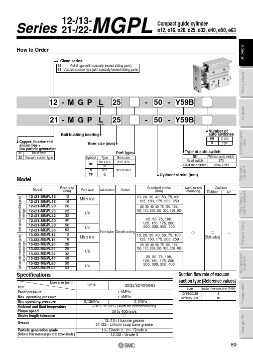
How to Order
5 to 40mA
Ț
switch 3-wire type
D-Y59A
28 VDC or less
40mA or less
Ț
24 VDC Relay, PLC IC circuit, Relay, PLC
Refer to applicable auto switch list — Page 182.
PLC: Programmable Logic Controller
20 76
93 117 135 66 37 10 10 10
Hale Waihona Puke 275169 10 19 9 36 10.5 8.5 83
25 82.5 98.5 117.5 135 66.5 37.5 12 13 16
32
51 68.5 10 19 9 42 11.5 9 93
Bore size
HA
J
K
L
MM ML NN OA OB OL
25, 50, 75, 100, 125, 150, 175, 200, 250, 300, 350, 400
12/16
20/25/32/40/50/63
1.5MPa
1.0MPa
0.12MPa
0.1MPa
–10°C to 60°C (With no condensation)
50 to 400mm/s
Bore size
WA
30st or Over 30st and Over 100st and Over 200st and less up to 100st up to 200st up to 300st
Over 300st
12 20 40 110 200 –
Mainframe Parts Impulse-12和Impulse-20的用户手册说明书

Mainframe PartsImpulse-12:99-1060-1 (Domestic) -1X (Export)Front panel metal only: 80-1666Back panel metal only: 80-1667Power Supply: 50-21Power Entry Module: 90-1177AC Cord: 30-49Bargraph/Clock/Timer assy: 99-1050Clock/Timer Lens: 80-1121Bargraph Lexan: 80-1622 (x2)10-LED Display: 12-59Cue/talkback speaker: 23-2FRAMEImpulse console assy: 99-1040-x #Lower Chassis assy: 90-1662-x #4.5" x 2.25" user panel: 80-1663-1(standard)4.5" x 6" user panel: 80-1663-2 (standard)3" x 6" user panel: 80-1663-31.5" x 6" user panel: 80-1663-4Screws, 4-40 x 1/4” hex: 38-894-40 washers: 38-10Manual: 75-42Service CD-ROM: 99-4804Connector Kit: 76-899 (Impulse-12)Connector Kit: 76-900 (Impulse-20)Tool Kit: 76-901Shipping crate:88-156 (Impulse-12)88-157 (Impulse-20)90-1660-x #"Coffee Guard":80-1675-x #Copystands:99-1067-x #WIRINGFlex cable, 18-cond: 19-58Flex cable, 18-cond: 19-59Flex cable, 18-cond: 19-60Flex cable, 6-cond: 19-61Timer cable: 90-1170Cue speaker cable: 90-1162Bargraph meter cable: 90-1163DC power cable: 90-1169*Complete assembly, with meters, cue speaker, clock/timer and all wiring for either frame size.# -1 is Impulse-12, -2 is Impulse-20Internal Board SettingsOutput PCA: 95-1045-32x3 connectors (x10): 14-4832x4 connector: 14-485DIP switch: 26-208Trimpot, 2k (x7): 24-165Trimpot, 1k: 24-16710 uF e-cap (x23): 60-127Parlex Cables 19-5817"RLS/Timer, 18 conductor (left end)19-5911"Monitor/Meter, 18 conductor (right end)19-604"Dual Channel, 18 conductor 19-614"Talkback, 6 conductor95-106032-pin Motherboard Interconnect PCA 95-10614-pin Motherboard Interconnect PCADual Input PCA: 95-1049-1A/B Input switch (white): 25-853Pgm switches (white): 25-853Offline switch (orange): 25-856Cue switch (yellow): 25-855Fader assembly: 95-1044Fader knob (white): 32-719-1Mounting screws: 38-91On switch w/buttoncap: 25-858-1 *Off switch w/buttoncap: 25-859-1 *ON buttoncap: 25-871-1 *OFF buttoncap: 25-872-1 *Lamp assy. (lamp & housing): 12-95Bare lamp: 12-101(Use 99-1041 for analog input, 99-1042-1 for AES or S/PDIF digital inputs or 99-1042-2 for EIAJ optical input)1112ON OFF ONOFF Alternate Knob ColorsBlack: 32-710-1Red: 32-712-1Y ellow: 32-714-1Green: 32-715-1Blue: 32-716-1Gray: 32-720-1Orange: 32-721-1*no suffix for blank buttoncap, -CU for custom engraving.Two lines per buttoncap, 4 1/2 characters max. per line.Dual T elco PCA: 95-1049-2AutoFeed switch (red): 25-854A/B Input switch (white): 25-853Pgm switches (white): 25-853Offline switch (orange): 25-856Cue switch (yellow): 25-855Upgrade kit: 76-906Telco FPGA: 21-194-4DSP FPGA: 21-210-4Extraction Tool: 70-130Install Doc: 71-1132Fader assembly: 95-1044Fader knob (white): 32-719-1Mounting screws: 38-91On switch w/buttoncap: 25-858-1 *Off switch w/buttoncap: 25-859-1 *ON buttoncap: 25-871-1 *OFF buttoncap: 25-872-1 *Lamp assy. (lamp & housing): 12-95Bare lamp: 12-101*no suffix for blank buttoncap, -CU for custom engraving.Two lines per buttoncap, 4 1/2 characters max. per line.CueAutoFeedPgm-1Pgm-2Pgm-3Off-LineCueTelcoTelco 2Telco 1ON OFF ON OFF Alternate Knob ColorsBlack: 32-710-1Red: 32-712-1Y ellow: 32-714-1Green: 32-715-1Blue: 32-716-1Gray: 32-720-1Orange: 32-721-1Monitor ControlsMonitor/Meter switchboard: 95-1046-2 Array Select Switch (white) (x14): 25-853Cue pot assy: 90-1165Pot only: 24-98knob: 90-327-1cap: 33-127Mic w/cable: 90-1171Mic element only: 23-1Grill: 80-917H/P pot assy: 90-1166Pot only: 24-100Knob: 32-159Skirt: 32-137Cap: 32-160CR Monitor pot assy: 90-1167Pot only: 24-100Knob: 32-159Skirt: 32-137Cap: 32-160Studio Monitor pot assy: 90-1164Pot only: 24-100Knob: 32-159Skirt: 32-137Cap: 32-160H/P jack assy: 90-1168Jack only: 17-22Talkback Switch assy: 95-969-2Switch: 25-860Lamp assy. (lamp & housing): 12-95Bare lamp: 12-101Timer & RLS ControlsTimer/RLS PCA: 95-1046-1Switch (white) (x19): 25-853AutoReset Hold Start StopTimerRemote Line SelectorMic Preamp PCA95-1045-1 Mic Preamp CardInputs 1 &2Outputs PCA: 95-1045-12x3 connector (x6): 14-483Preamp IC: 22-11Op amps: 22-13Trimpots: 24-170DIP switch: 26-2447 uF e-cap (x12): 60-10822 uF e-cap (x8): 60-125TALK BACKCOUGHONOFFMic Remote Panel 99-949-1 & 99-949-299-949-1 Panel: 80-157799-949-2 Panel: 80-1576 (shown)Switch guard (x2): 80-1502Switch w/white engraved button: 25-860-1Switch: 25-860Switch w/orange engraved button: 25-874-1Switch: 25-874Switch w/red engraved button: 25-858-1Switch: 25-858Switch w/yellow engraved button: 25-859-1Switch: 25-85999-949-1: Cabinet mount 99-949-2: Turret mountPCA: 95-949PCB Connector: 15-5833-pin Header: 14-20Header jumper: 14-69Installation guide: 74-134Connector kit: 76-737Documentation: 71-949Connector Housing: 15-524Terminal pins (x10): 15-8Cabinet Grommet: PRE-3759PR&E #Description or Use12-95On, Off, Talkback lamp & housing12-101On, Off, Talkback lamp only24-98Cue Pot24-100CR and Studio Monitor, Headphone Pot 25-853Pgm and A/B select switch25-854Autofeed switch25-855Cue switch25-856Off/Line switch25-858Module On switch25-859Module Off switch25-860Talkback switch25-870White button cap25-871Red button cap25-872Yellow button cap95-1044Input & Telco channel fadersPR&E #Description or Use Qty. 76-899Inpulse-12 Connector Kit—14-4823-pin AMP housing3 14-4846-pin AMP housing58 14-4868-pin AMP housing2 14-50024-pin AMP housing12 15-938-1Receptacle contacts54976-900Impulse-20 Connector Kit—14-4823-pin AMP housing3 14-4846-pin AMP housing74 14-4868-pin AMP housing2 14-50024-pin AMP housing20 15-938-1Receptacle contacts770 76-901AirWave Tool Kit 50-5AA Lithium battery2 70-126Crimp Tool1 70-129Contact Removal Tool1 90-151Clock Magnet Tool1 Connector and Tool Kit ComponentsAirWave Digital Assemblies & ModulesPR&E #Description or Use PR&E #Description or Use23-1Electret microphone23-2Cue speaker50-21Power Supply80-1121Clock/Timer bezel80-1663-4 1.5" x 6" Blank Panel 80-1663-33" x 6" Blank Panel80-1663-2 4.5" x 6" Blank Panel 80-1663-1 2.25" x 4.5" Blank Panel 95-1044Fader assy.95-1045-1Microphone preamp PCA 95-1045-3Output Amplifier PCA95-1046-1Remote Line Selector/Timer switchboard95-1046-2Monitor/Meter Select switchboard 95-1049-1Dual Input Control PCA95-1049-2Dual Telco Control PCA99-1041Analog Input Config Card99-1042-1AES Input Config Card99-1042-2Optical Input Config Card99-1045-2RLS Selector PCA99-1047Right DSP Card99-1048-1Left DSP Card99-1048-2Middle DSP Card (Impulse-20 only) 99-1050Bargraph Meter assy.99-1067-1Copy Stand for Impulse-1299-1067-2Copy Stand for Impulse-20Impulse Replacement Parts Parts Summary。
MP020-5

ELECTRICAL CHARACTERISTICS
VCC = 15V, TA = 25°C, unless otherwise noted.
Parameter Symbol Condition Min Supply Voltage Management (VCC Pin) VCC ON threshold VCCH VCC OFF threshold VCCL VCC operating voltage Quiescent current Iq At no load condition, Vcc=20V Operating current IOP Internal MOSFET (Drain Pin) Break-Down Voltage VBRDSS Supply current from Drain pin Icharge Leakage current from Drain pin Ileak VDS=500Vdc ID=10mA, Tj=20 degree On-State MP020-5 Ron resistance Minimum switching frequency fmin At no load condition Internal Current Sense Current Limit MP020-5 ILimit Leading edge blanking tLEB Feedback input (FB Pin) FB pin input current IFB VFB=4V Feedback threshold VFB DCM detect threshold VDCM FB open-circuit threshold VFBopen FB OVP threshold VFBovp OVP sample delay tOVP Output Cable Compensation (CP Pin) Cable compensation voltage VCP fS=70kHz Thermal Shutdown Thermal shutdown threshold Thermal shutdown recovery threshold Typ 17
GRP-520产品快速启动指南说明书

GRP-520 Quick Start v1.00 2013/03/20GRP-520Quick StartPackage ChecklistThe package includes the following items:●One GRP-520 hardware module●One Quick Start●One companion CD●One RS-232 cable (CA-0910)●One 2G/3G antenna (ANT-421-02)●Screw DriverRelated Documents and Software UtilitiesDocuments●User Manual: GRP-520_User_Manual.pdf●Quick Start: GRP-520_QuickStart.pdf●CD:\napdos\GRP-520\Manual●/pub/cd/usbcd/napdos/GRP-520/manualGRP-520 Dimensions (Unit: mm)Appearance and Pin AssignmentsLED indicatorsA.PWR(Green):Power LED to indicate whether the external power is input or not. Thedescription is as follows:B.OS(Red):OS LED indicates if the OS is normal or fail.C.FW(Red):This LED indicates the status of VxServer firmware (Serial port to 3G).D.3G (Red):The LED indicates the status of 3G module.InstallationIf users want to start GRP-520 normally, it needs to follow these steps to install the GRP-520 below:A.Install the antennaB.Plug in the normal SIM card (Before apply the SIM card, confirm it is OK by mobilephone.)C.Plug the Ethernet cable if you need it.D.If you want to use the Micro SD card, please insert it into the slot.E.Turn the rotary switch to 0 (normal mode). The COM1 will be the console in position 1(debug mode), and the default username is “root”, default password is “root”.F.Connect the DC.+VS and DC.GND to the power supply.G.It is needed to wait about 20 ~ 30 seconds for OS booting. After finishing the process,GRP-520 would be in normal operation mode and the OS LED would blank as heart beatper 1 sec.H.It is needed to wait about 30 ~ 60 seconds to search the 3G/2G base and register to the ISP.After finishing the process, the 3G LED would blank per 1 sec.Web Utility1. LoginDefault username = “admin”, and default password = “admin”Default IP = “192.168.255.1”Default Mask = “255.255.0.0”Default Gateway = “192.168.0.1”After login, the screenshot is showed as below:2. EthernetThis page provides the basic settings of Ethernet:(1)Mode:.“Static”: set as static IP.”DHCP”: set IP via DHCP protocol.(2)IP Address: IP of Ethernet.(3)Mask: the Mask of the gateway.(4)Gateway: IP of the gateway.3. 3G ConfigureThis page provides basic settings of 3G network.(1)PIN Code: PIN Code are 4 character number provided by SIM Card provider(2)Phone Number: usually fill it as “*99***1#” or “*99#”. The number is depended on SIMCard provider(3)APN: Access Point Name, please ask your SIM Card provider.(4)User Name: the username for dial-up. Please ask your SIM Card provider.(5)Password: the password for dial-up. Please ask your SIM Card provider.(6)Auto-Dialing: Enable this function to dial-up to 3G network after power on.4. RoutingThis page provides routing rule configuration.(1)IP: IP address.(2)Mask: the mask will effect how many IP this rule manages.”24” = 255 IPs, “28” = 16 IPs, “32” = 1 IPs.(3)Target: the target interface of the rule.(4)For example:The Rule 0: This rule will push the socket packages from the address 192.168.27.0 ~ 192.168.27.255 forward to “ppp0” (3G network).The Rule 0: This rule will push the socket packages from the address 192.168.0.0 ~ 192.168.0.15 forward to “ppp0” (3G network).5. Port Mapping (Port Forward)This page provides Port Mapping rule configuration.(1)Type: the protocol type. There are “TCP” and “UDP”(2)From: the interface that the socket comes from.”ppp0” is 3G interface.(3)Port: the port that the socket comes from.(4)Target IP: the IP that the socket goes forward.(5)Target Port: the Port of the “Target IP”.(6)For example:The Rule 0: This rule will bind the socket from the “ppp0”and Port=”10080”with 192.168.0.10:80.The Rule 1: This rule will bind the socket from the “ppp0”and Port=”10021”with 192.168.0.10:21.6. PasswordThe user can change the password of the web utility here.(1)Password: new password.(2)Confirm: confirm the password again.7. The advance settings of web utilityPlease refer the user manual of GRP-520.Technical Support1. ICP DAS Service : ******************2. GRP-520 software Website:/GRP-520.html。
MICOM-P520-电动机保护资料
!"#$%&'"#$()
!(
)
:90%
!"#$%&'
!"#$% !"#$% !"#$ !"#$ % !"
!"#$%& !"# !" !" !" #
!"#$%&'()*+,
!"#$%
!" äÉÖE
!"#$ I
F
1
!"#$
!"#$%&'( !"#$%&' MiCOM P225
!"#$%&'()*+,
2
!"#$
!"# 52 52+ !
!
1 0.1s 1 - 5 Iθ
!" Istart 0.5 Iθ 1s
CT
CT 1 - 3000A CT 1 - 3000A CT 1A 5A CT 1A 5A !"# CT 5P10-5VA !" CT CT !" CT !"#$%&'()*+ ! 1A 1A
! 0 - 100s !" /
!"#$%&'( )
4 MiCOM S10
!
!"#$%&'()*+, !"#$% !"
3 MiCOM S1 !" !"#$%&
!"#$
!"# !"# !
$%&'"() !"# !%&' !"#$% MiCOM