A 884 – A 884M – 02 _QTG4NC9BODG0TQ__
WBH-822A技术及使用说明书V1.0

adg884brmz工作原理

adg884brmz工作原理
adg884brmz是一种电子器件,其工作原理涉及到信号开关和信号转换的操作。
作为一个数字分析器件,adg884brmz能够灵活地控制和管理不同信号之间的连接和断开。
在adg884brmz的内部,有一个由多个互补金属-氧化物半导体场效应晶体管(CMOS FETs)构成的矩阵。
这些FETs可以被控制来打开或关闭信号路径,从而实现信号的路由和转换。
当某个FET被打开时,相应的信号就可以通过该路径传输;而当FET关闭时,则会隔离该路径,阻断信号传输。
adg884brmz通过输入控制信号来操作内部FETs的开关状态,这些控制信号可以来自外部的逻辑电平或数字信号。
通过控制信号的变化,可以实现不同信号路径的连接和断开。
这种灵活的信号控制方式使得adg884brmz可以被广泛应用于电子系统中,如数据转换、信号选择、信号多路复用等功能。
adg884brmz还具有低电平电阻、低电流漏和功耗小的特点,使得其在高性能和低功耗要求的应用领域中具备竞争力。
其可靠性和稳定性也使得adg884brmz成为了许多电子系统设计中不可或缺的关键器件之一。
adg884brmz作为一种数字分析器件,通过控制信号开关和转换不同信号路径,从而实现信号的连接和断开。
它的工作原理严谨可靠,并具有低阻抗、低漏电流和低功耗等优势,使其在各种电子系统中得到广泛应用。
信任 8通道电阻温度计(RTD)场地终端集装箱(FTA) T8841说明书

PD-T8841 TrustedTrusted 8 Channel RTD FTAProduct OverviewThe Trusted® 8 Channel Resistance Temperature Detector (RTD) Field Termination Assembly (FTA) T8841 provides an interface between a Trusted System and up to eight Platinum 100 Ω RTD sensors which may be connected using 2 or 3-wire configurations.Each RTD FTA channel may be configured to provide either a scaled current output in the range of 4 20 mA, or a scaled voltage output in the range of 1 5 Vdc. The RTD FTA also provides sensor excitation and linearisation for each channels.Features:•Eight input channels per RTD FTA.•Industry standard field device connections.•Standard DIN rail compatibility.•Simple installation and connection.•24 Vdc operation.•Configurable 2 or 3 wire inputs.•Configurable current or voltage output.Trusted PD-T8841Page intentionally left blankTrusted 8 Channel RTD FTA PREFACE PREFACEIn no event will Rockwell Automation be responsible or liable for indirect or consequential damages resulting from the use or application of this equipment. The examples given in this manual are included solely for illustrative purposes. Because of the many variables and requirements related to any particular installation, Rockwell Automation does not assume responsibility or reliability for actual use based on the examples and diagrams.No patent liability is assumed by Rockwell Automation, with respect to use of information, circuits, equipment, or software described in this manual.All trademarks are acknowledged.DISCLAIMERIt is not intended that the information in this publication covers every possible detail about the construction, operation, or maintenance of a control system installation. You should also refer to your own local (or supplied) system safety manual, installation and operator/maintenance manuals.REVISION AND UPDATING POLICYThis document is based on information available at the time of its publication. The document contents are subject to change from time to time. The latest versions of the manuals are available at the Rockwell Automation Literature Library under "Product Information" information "Critical Process Control & Safety Systems".TRUSTED RELEASEThis technical manual applies to Trusted Release: 3.6.1.LATEST PRODUCT INFORMATIONFor the latest information about this product review the Product Notifications and Technical Notes issued by technical support. Product Notifications and product support are available at the Rockwell Automation Support Centre atAt the Search Knowledgebase tab select the option "By Product" then scroll down and select the Trusted product.Some of the Answer ID’s in the Knowledge Base require a TechConnect Support Contract. For more information about TechConnect Support Contract Access Level and Features please click on the following link:https:///app/answers/detail/a_id/50871This will get you to the login page where you must enter your login details.PREFACE Trusted 8 Channel RTD FTA IMPORTANT A login is required to access the link. If you do not have an account then you can create one using the "Sign Up" link at the top right of the web page.DOCUMENTATION FEEDBACKYour comments help us to write better user documentation. If you discover an error, or have a suggestion on how to make this publication better, send your comment to our technical support group at Trusted 8 Channel RTD FTA PREFACESCOPEThis manual specifies the maintenance requirements and describes the procedures to assist troubleshooting and maintenance of a Trusted system. WHO SHOULD USE THIS MANUALThis manual is for plant maintenance personnel who are experienced in the operation and maintenance of electronic equipment and are trained to work with safety systems. SYMBOLSIn this manual we will use these notices to tell you about safety considerations.SHOCK HAZARD: Identifies an electrical shock hazard. If a warning label is fitted, it can be on or inside the equipment.WARNING: Identifies information about practices or circumstances that can cause an explosion in a hazardous environment, which can cause injury or death, property damage or economic loss.ATTENTION: Identifies information about practices or circumstances that can cause injury or death.CAUTION: Identifies information about practices or circumstances that can cause property damage or economic loss.BURN HAZARD: Identifies where a surface can reach dangerous temperatures. If a warning label is fitted, it can be on or inside the equipment.This symbol identifies items which must be thought about and put in place when designing and assembling a Trusted controller for use in a Safety Instrumented Function (SIF). It appears extensively in the Trusted Safety Manual.IMPORTANTIdentifies information that is critical for successful application and understanding of the product.NOTE Provides key information about the product or service.TIP Tips give helpful information about using or setting up the equipment.PREFACE Trusted 8 Channel RTD FTAWARNINGS AND CAUTIONSWARNING: EXPLOSION RISKDo not connect or disconnect equipment while the circuit is live or unless the area is known to be free of ignitable concentrations or equivalentAVERTISSEMENT - RISQUE D’EXPLOSIONNe pas connecter ou déconnecter l’équipement alors qu’il est sous tension, sauf si l’environnement est exempt de concentrations inflammables ou équivalenteMAINTENANCEMaintenance must be carried out only by qualified personnel. Failure to follow these instructions may result in personal injury.CAUTION: RADIO FREQUENCY INTERFERENCEMost electronic equipment is influenced by Radio Frequency Interference. Caution should be exercised with regard to the use of portable communications equipment around such equipment. Signs should be posted in the vicinity of the equipment cautioning against the use of portable communications equipment.CAUTION:The module PCBs contains static sensitive components. Static handling precautions must be observed. DO NOT touch exposed connector pins or attempt to dismantle a module.Trusted 8 Channel RTD FTA PREFACE ISSUE RECORDIssue Date Comments5 Sep 05 Format6 Nov 07 Cable advice7 Jun 16 Rebranded and updated to incorporate IEEE standards with correction oftypographical errors and also standardise the Relative Humidity Rangeand Operating Temperature statements in the Specification Section.PREFACE Trusted 8 Channel RTD FTAPage intentionally left blankTrusted 8 Channel RTD FTA Table of Contents Table of Contents1.Description (3)2.System Functions (5)2.1. Zero, Gain & Linearisation (5)3.Installation (7)3.1. Cable Selection (7)4.Assembly Pinout Connections (9)4.1. RTD1 to RTD8 (9)4.2. IOIF (9)4.3. PWR (10)5.Link Assignments (11)5.1. Two Wire Operation (11)5.2. Voltage Output (11)5.3. Measurement range 0 °C to 1000 °C (12)5.4. Measurement range 0 °C to 3000 °C (13)6.Specifications (15)Table of Contents Trusted 8 Channel RTD FTAPage intentionally left blankTrusted 8 Channel RTD FTA 1. Description 1.DescriptionFigure 1 T8841 LayoutFigure 1 shows a single channel of the RTD FTA. All eight channels are identical.Figure 1 Single Channel CircuitEach channel of the RTD FTA contains a precision RTD instrumentation amplifier circuit based on the Burr Brown XTR105 device. The device is a monolithic 4 mA to 20 mA, 2-wire current transmitter with two precision current sources. It provides complete current1. Description Trusted 8 Channel RTD FTA excitation for Platinum RTD temperature sensors and bridges, an instrumentation amplifier and current output circuits on a single integrated circuit.The amplifier gain can be configured for a wide range of temperature measurements. Total unadjusted error of the complete current transmitter is low enough to permit use without adjustment in many applications. This includes zero output current drift, span drift andnon-linearity.Each circuit contains configuration links allowing user selection of the following: •Input temperature measurement range.•Two and three wire input sensor operation.•Voltage output when appropriate links are fitted.•Amplifier gain.•Linear resistors.•Zero resistors.The input temperature measurement range is individually configurable on each channel. The minimum temperature setting for each of the two configurable ranges per channel can be factory pre-set over the range -200 °C to 800 °C. The temperature measurement range for each of the two configurable ranges per channel can be factory pre-set over the range100 °C to 1000 °C.Each RFTA temperature output is configurable for the following:• 4 mA to 20 mA current source output.•0 Vdc to 5 Vdc voltage source output.The 4 mA to 20 mA current source output is the preferred option. The 0 Vdc to 5 Vdc option provides an overall operating range of 0 Vdc to 5 Vdc with a healthy field loop operating range of 1 Vdc to 5 Vdc.RTD devices in the field are connected to the RTD FTA by cables terminated at eight 3-way connectors (RTD1 to RTD8). The eight temperature outputs from the RFTA is via a 10-way connector (IOIF). The dual 24 Vdc power supplies are connected to the RFTA via a 4-way connector (PWR).Trusted 8 Channel RTD FTA 2. System Functions 2.System Functions2.1.Zero, Gain & LinearisationThe RTD linearisation for each channel is controlled by two factory pre-set linearisation resistances, RLIN1 and RLIN2. These values are dependent upon the zero and full scale settings required for that channel. Each channel has provision for two separate link selectable values for both RLIN1 and RLIN2.The zero setting for each channel is controlled by the factory pre-set zero resistance, Rz. Each channel has provision for two separate link selectable values for Rz.The full scale setting for each channel is controlled by the factory pre-set gain resistor Rg. Each channel has provision for four separate link selectable values for Rg.2. System Functions Trusted 8 Channel RTD FTAPage intentionally left blankTrusted 8 Channel RTD FTA 3. Installation3. InstallationThe Trusted 8 Channel RTD FTA T8841 is designed to be mounted on either of the TS32 or TS35 DIN rails in the horizontal or vertical positions.3.1. Cable SelectionThe Trusted 8 Channel RTD FTA can connect direct to an Analogue Input Module using either companion cables TC-211/212 or smart-slot cables TC-511/512. The Output can also be connected to the Analogue Input module via a Versatile Field Termination Assembly(VFTA) if necessary to be compatible with an existing installation, where complete groups of channels can be wired to T8841 FTAs or other inputs as required.Figure 2 Typical configurationAnalogue module 8431RTD FTA 8841RTD FTA8841RTD FTA 8841RTD FTA 8841RTD FTA 8841TC-211/212Up to 8 RTD devices3. InstallationTrusted 8 Channel RTD FTAFigure 3 Configuration using VFTAVFTA 8842RTD FTA 8841 Or separate inputsRTD FTA 8841Or separate inputsRTD FTA 8841 Or separate inputsRTD FTA 8841 Or separate inputsRTD FTA 8841 Or separate inputsUp to 8 RTD devicesAnalogue module 8431Trusted 8 Channel RTD FTA 4. Assembly Pinout Connections 4.Assembly Pinout Connections4.1.RTD1 to RTD8Pin Service RTD Sensor Cable Colour 2-Wire 3-Wire1 (W) + Input White White2 (R) + Input Red Red3 (R) I Return RedTable 1 RTD Connections 4.2.IOIFPin Service1 0 V earth reference2 Channel 1 temperature output3 Channel 2 temperature output4 Channel 3 temperature output5 Channel 4 temperature output6 Channel 5 temperature output7 Channel 6 temperature output8 Channel 7 temperature output9 Channel 8 temperature output10 0 V earth referenceTable 2 IOIF Connections4. Assembly Pinout Connections Trusted 8 Channel RTD FTA 4.3.PWRPin Service1 24 V-12 0 V3 0 V4 24 V-2Table 3 PWR ConnectionsTrusted 8 Channel RTD FTA 5. Link Assignments 5.Link AssignmentsThe functions of the links are detailed below.5.1.Two Wire OperationThe links listed in the table below must be fitted for 2-wire operation. The RTD FTA defaults to 3-wire operation if the links detailed are not fitted.Channel Link1 LK932 LK893 LK944 LK905 LK956 LK917 LK968 LK92Table 4 Two Wire Link Assignments5.2.Voltage OutputThe links listed in the table below must be fitted for voltage output. The RTD FTA defaults to current output operation if the links detailed are not fitted.Channel Link1 LK12 LK453 LK24 LK465 LK35. Link Assignments Trusted 8 Channel RTD FTAChannel Link6 LK477 LK48 LK48Table 5 Voltage Output Link Assignments5.3.Measurement range 0 °C to 1000 °CThe links listed in the table below must be fitted to enable the RTD FTA to measure temperatures in the range 0 °C to 100 °C.Channel Link1 LK5, LK6, LK21, LK29, LK31,2 LK49, LK50, LK65, LK73 LK75,3 LK9, LK10, LK23, LK33, LK354 LK53, LK54, LK67, LK77, LK795 LK13, LK14, LK25, LK37, LK396 LK57, LK58, LK69, LK81, LK837 LK17, LK18, LK27, LK41, LK438 LK61, LK62, LK71, LK85, LK87Table 6 Range 0 °C to 100 °C Link AssignmentsTrusted 8 Channel RTD FTA 5. Link Assignments 5.4.Measurement range 0 °C to 3000 °CThe links listed in the table below must be fitted to enable the RTD FTA to measure temperatures in the range 0 °C to 3000 °C.Channel Link1 LK7, LK8, LK22, LK30, LK322 LK51, LK52, LK66, LK74, LK763 LK11, LK12, LK24, LK34, LK364 LK55, LK56, LK68, LK78, LK805 LK15, LK16, LK26, LK38, LK406 LK59, LK60, LK70, LK82, LK847 LK19, LK20, LK28, LK42, LK448 LK63, LK64, LK72, LK86, LK88Table 7 Range 0 °C to 300 °C Link Assignments5. Link Assignments Trusted 8 Channel RTD FTAPage intentionally left blankTrusted 8 Channel RTD FTA 6. Specifications 6.SpecificationsNumber of Inputs 8 Channels (2 or 3-wire)Voltage Range 20 Vdc to 32 VdcPower Isolation ±250 VdcPower Consumption (per channel @24V dc) 60 mW to 720 mWSensor Excitation Current 0.8 mACurrent Output (normal operating range) 4 mA to 20 mAOperating Temperature 0 °C to +60 °C (+32 °F to +140 °F)Non-operating Temperature -25 °C to +70 °C (-13 °F to +158 °F)Relative Humidity range10 % – 95 %, non-condensing(operating, storage & transport)Environmental Specifications Refer to Document 552517DimensionsHeight 110 mm (4.3 in)Width 145 mm (5.7 in)Depth 68 mm (2.6 in)Weight 248 g (0.55 lb)。
★MDM300.I.S★

英国密析尔MICHELL 仪表制造商露点变送器,dewpointmeters ,冷/冷镜湿度计,相对湿度传感器,过程水分测定仪,碳氢露点分析仪,液体分析仪中的水分和氧气分析仪,是一家国际领先的高精度传感与结束在该领域有30多年的经验。
我们的产品范围的高精度电容湿度传感器,帮助客户测量微量水分,在其过程中的应用,而我们的相对湿度变送器,相对湿度和温度传感器被广泛应用于HV AC 应用,药品储存等生产流程控制的环境条件是至关重要的。
,再加上我们的参考露点湿度计,湿度校准系统使客户能够进行校准便携式湿度计和相对湿度的仪器内部的,节省费用和停机时间。
我们提供高速测量中的应用范围,包括发电站,燃烧优化控制CO 2的水平啤酒厂,清洁气体的过程,如硅片生产和纯气体生成氧气。
天然气行业和发电厂的客户节省数百万美元的维修和停机时间,通过使用我们的康达迈科Condumax II 烃露点分析仪,以确保传输的天然气质量在贸易交接,防止燃气燃烧器故障,延长寿命过程的设备。
我们在烃类液体中的水分分析仪适用于防爆,本质安全和实验室版本,并允许范围广泛的烃类液体,包括变压器油,液压油,石油馏分和纯烃中的水分含量的连续测量。
一个高速的便携式露点仪,提供快速的现场检查在许多应用中,包括压缩空气,天然气和高电压开关淬气露点或水分含量测量。
这款轻巧,ATEX ,IECEx 认证,FM ,CSA ,GOST 认证产品比其他任何同类产品让更多的测量每工作小时。
硬质耐磨,但符合人体工程学的情况下和一个易于使用的接口,可以在恶劣的工业环境中的舒适和实际操作。
产品特点∙ 在低压下从T95至-60℃,小于15分钟时间反复快速的测量∙ 更高的压力测量成为可能 - 高达350巴 ∙ 电池寿命长:长达48小时的典型使用费用之间∙ 直观的应用套件,允许快速和简单的连接到您的采样点∙ 耐用,易于处理和操作:专为在工业环境中使用∙ 4-20 mA 外部设备输入变送器校准和验证∙ 轻量级:小于1.5公斤 ∙13点可溯源校准证书MDM300的MDM300采样选项MDM300 MDM300要获得最佳性能,它是为您的测量点有适当的样品调节至关重要。
星级酒店弱电系统报价单
二、现场直接数字式控制器(DDC)
三、现场末端装置(传感器及执行机构)
小计
电视监控系统
序号
1 2 3 4 5 6
设备名称 数字硬盘录像机 液晶显示器 硬盘 室内一体化高速半球型摄像机 高清彩色红外半球 电梯专业半球摄像机
规格型号 HDB-DVR416E 19寸 2T HDB-527PCB-3 HDB-701MM HDB-9003WCB
系统调试
5
6
7
8
9
10
11
12
大口径—1.2m MW-MOD-9631 MW-BLE-L32-*/* 5-1000MHzH通用型(室内型、中号外 壳) 5-1000MHzH通用型(室内型、中号外 壳) 5-1000MHzH通用型(室内型、中号外 壳) 5-1000MHzH通用型(室内型、中号外 壳) 5-1000MHzH通用型(室内型、中号外 壳) 5-1000MHzH通用型(室内型、中号外 壳) 5-1000MHzH通用型(室内型、中号外 壳) 5-1000MHzH通用型(室内型、中号外 壳) 5-1000MHzH通用型(室内型、中号外 壳) SYV-75-5
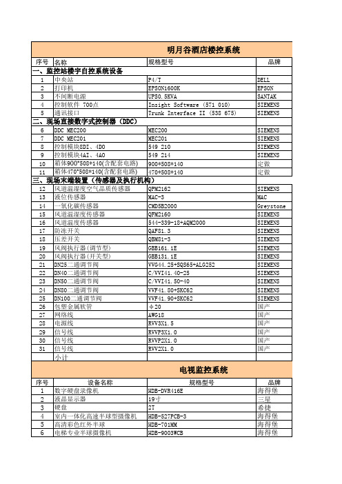
明月谷酒店楼控系统序号名称规格型号品牌数量单位单价合计一监控站楼宇自控系统设备中央站p4tdell打印机epson1600kepson不间断电源ups05kvasantakinsightsoftware571010siemens通讯接口trunkinterfaceii538675siemensddcmec200mec200siemensddcmec201mec201siemens549210siemens549214siemens10定做11定做三现场末端装置传感器及执行机构12风道温湿度空气品质传感器qpm2162siemens13液位传感器mac3mac14一氧化碳传感器cmd5b2000greystone15风道温湿度传感器qfm2160siemens16风道温度传感器54433918aqm2000siemens17防冻开关qaf813siemens18压差开关qbm813siemens19gbb1611esiemens20gbb1311esiemens21vvg4425sqs65alg252siemens22cvvi414025siemens23cvvi415040siemens24vvf4180skc62siemens25vvf4190skc62siemens26包塑金属软管20国产27网络线awg18国产28电源线rvv3x15国产29信号线rvvp3x10国产30信号线rvvp2x10国产31信号线rvv2x10国产小计电视监控系统序号设备名称规格型号品牌数量单位单价合计数字硬盘录像机hdbdvr416e液晶显示器三星11硬盘2t希捷11室内一体化高速半球型摄像机hdb527pcb3高清彩色红外半球hdb701mm电梯专业半球摄像机hdb9003wcb彩色红外高清摄像机hdb5680yc视频矩阵hdbd2025a25616控制键盘hdbd207810视频分配器hdbd1632v11高清彩色逐行监视器hdbcm21aa12电视墙及操作台1611定制13电源12v2a国产14214球机电源24v2a国产26156kw16视频线syv755国产1100017电源线rvv210国产300018控制线rvvp210国产1100国产40019管材国产400021系统调试22小计电子巡更系统感应巡更棒0compa1602ocom通讯座0compbu320ocom地点识别卡pid2ocom120人员识别卡ocom5
Fluke8840A数字多用表原理及检修

值/ 直流变换器 U802 。U802 对输
入信号作平方 ( V i n2) 再与输出作除
法运 算 得
U ov t
=
(
V
2
in )
V out
=
V
2 in
。
最后经 J 2014 脚 、U302C 耦合进入
T/ H 电路 ,与直流分量合成得到真
有效值测量 。交流电流也是先变换
成交流电压 ,再参照交流电压进行
放大器的 U103 ,作为模拟量输入 。 (4) 精密基准电压与欧姆测量 8840A 为 A/ D 变换器和欧姆电
流源设置了一个精密基准电压 ,它 提供了 - 7. 00000V 和 + 7. 00000V 的精密电压 。欧姆电流源为欧姆功 能提供一个精密的测试电流 。 7. 00000V 的精密基准电压在精密 电阻 R401 上产生了一个精密的基 准电流 ,第二放大器 U404 与精密电 阻网 络 Z401 、模 拟 开 关 U402 和 U403 构成一个电流放大器 ,其输出 电流大小由 CPU 控制模拟开关的 通断来选择 。两线欧姆测量是通过 K401 继电器将欧姆电流源的电流 输送到被测电阻 ,在被测电阻上产 生电压降 ,再将此电压按 DCV 量值 进行测量 。四线欧姆测量与两线基 本一样 ,只是将测试端改由 ( SENSE HI LO) 端输入 ,跳过前端的高电阻 网络 ,有效地消除了测试线的阻值 影响 。
ML8824A系列电力线性阀门操纵器商品说明书

Electric Linear Valve ActuatorSafetyMaterialsProtection classIP54 (EN60730)Upper Cover PC plastics Housing 600N - Plasticsm u n i m u l a t s a C - N 0081BracketCast aluminumApplicationML8824A Series electric linear valve actuators o er modulating controls for linear valves with positionThe products can be widely used with linear valves in heating, ventilation, and air conditioning application.Features• Quick and easy installation • Lower power consumption • Maintenance-free • Self-adaption mode • Adjustable travel speed• Manual operation with override functions • 0(2)~10 Vdc, 0(4)~20 mA input signal• 0(2)~10 Vdc, 0(4)~20 mA position feedback signal•Selectable travel directionTechnical SpecificationsTemperature LimitsAmbient storage temperature Medium temperatureOperating medium temperature up to 130 °CSignalsInput signal 0~10 Vdc, 2~10 Vdce c n a d e p m i t u p n i e g a t l o V >100 K Ω,A m 02~4 ,A m 02~0 e c n a d e p m i t u p n i t n e r r u C<0.125K ΩFeedback signal 0~10 Vdc, 2~10 Vdc,Am 02~4 ,A m 02~0ML8824A SeriesWiringTable 1. Model SelectionModel No.ML8824A0620ML8824A1820ML8824A1840;%01-, %51+ c d V 42 ;z H 06/05, %51 ± c a V 42e g a t l o V y l p p u S Power Consumption A V 5.41AV 5.41A V 7Signal input 1The valve connection is located at the bottom; 2-way valve "closed"; 3-way valve A-AB port "open"①Signal input 2The valve connection is located on the top; 2-way valve "open"; 3-way valve A-AB port "closed"①Am 02~)4(0 ,c d V 01~)2(0l a n g i S k c a b d e e F Rated Travel m m 04m m 02m m 02s 021 r o s 08s06 r o s 04s 08 r o s 06e m i t n u R N0081≥N 006≥e c r o f f f o -e s o l C Weightg k 4.2g k 3.2gk 3.1① Factory setting. Reverse actuation can be conducted through the 5th DIP switch on PCB.Terminal block 1.5mm 2Cable connector PG13.5PG9 connector for accessories Operation0(2) Vdc or 0(4) mA 10Vdc or 20mAOperationWiring DescriptionThe actuator is pre-assembled with PG13.5 cable connector and provides PG13.5 and PG9 connectors for accessories.NOTE: To avoid any fault, please connect to 24 Vac power with ground connection (see the wiring diagram).Self-Adaption ModeAssemble the actuator and the valve, and supply the actuator with 24Vac/dc power.Power-on self-adaption: The actuator will directly enter into self-adaption mode after being powered up. Meanwhile, the yellow indicator on PCB blinks (1Hz) and the actuator will be automatically full o (traveling to the bottom) and then full on (traveling to the top). When the indicator stops blinking, it means that the process is completed. Afterwards, the actuator will travel to the designated position of control signal.Manual self-adaption: Press and hold button S1 on PCB for more than 5s (See Fig. 1) until the indicator starts blinking (1Hz) to enter into self-adaption mode. The actuator will be automatically full o (traveling to the bottom) and then full on (traveling to the top). When the indicator stops blinking, it means that the process is completed. Afterwards, the actuator will travel to the designated position of control signal.NOTE: The self-adaptation process with take 3 minutes for 600N actuator and 4 mins for 1800N actuator (under factory default setting)Manual OperationFloating Point Control SwitchingML8824 series actuators can be manually operatedthrough the accompanied hexagon wrench, and feature manual override function. In case of manual operation during power-on, the actuator will automatically cut o the power for the motor so as to ensure safety. NOTE: After manual operations are completed with power o , the self-adaption process must be reactivated!Rotate the hexagon wrench clockwise, and the actuator connection will move downwards; otherwise, the actuator connection will move upwards.ML8824 series actuators are provided with floating point control (see the wiring diagram). When the 8th DIP switch on PCB is ON, it indicates floating point control and the actuator will travel to the fully open or fully closed position without being controlled by the input signal.Input/Feedback SignalSignal Interruption Mode DescriptionSetting of Traveling DirectionFig. 1 PCB LayoutTable 2 DIP Switch SettingDIP SwitchFunction Function Description of Setting Value S2-1ON OFFS2-2ON II: The control signal is current type.OFF UI: The control signal is voltage type. (factory default)S2-3ON UI: The control signal is voltage type. (factory default)OFF II: The control signal is current type.S2-4ON IO: The feedback signal is current type. (factory default)OFF UO: The feedback signal is voltage type.S2-5ON DA: When control signal increases, actuator moves downward. When control signal decreases, actuator moves upward.OFF S2-6ONOFFS2-7ON DF: In power-on self-adaption mode. (factory default)OFF RF: In manual self-adaption mode.S2-8ON Floating controlOFFModulating control (factory default)S2-9 ReservedS2-10Speed settingONHigh speed: 600N - 3s/mm, 1800N - 2s/mmOFFLow speed: 600N - 4s/mm, 1800N - 3s/mm (factory default)The analog input/feedback signal is selectable through the DIP switch (see Table 2). The factory default input/feedback signal is 0...10 Vdc.It is also possible for the actuator to input/output2~10Vdc, 0~20mA, and 4~20mA signals, which requires changing of DIP switches on PCB (see Table 2).The signal interruption mode can be set through the 6th DIP switch (see Table 2).When the DIP switch is ON and the control signal is voltage or current type, the actuator will automatically provide a 0 (2) Vdc or 0 (4) mA signal (factory default) if the signal cable is cut.When the DIP switch is OFF and the control signal isvoltage type, the actuator will automatically provide a 10 Vdc signal if the signal cable is cut; in case of current type signal, the actuator will automatically provide a 0 (4) mA signal.The traveling direction can be set though the 5th DIP switch (see Table 2).When the DIP switch is ON, the input signal 0 (2) Vdc or 0 (4)mA is corresponding to the upper position of the actuator (factory default).When the DIP switch is OFF, the input signal 0 (2) Vdc or 0 (4) mA is corresponding to the lower position of the actuator.ReservedReservedSetting of control/feedback signalSetting of control signal type Setting of control signal input impedance matching Setting offeedback signal typeSetting ofoperating modeSetting of signal interruption modeSetting of self-adaption modeSetting of control mode20%: 4~20mA or 2~10VDC control/feedback signal0: 0~20mA or 0~10VDC control/feedback signal (factory default)DW: When the control signal type is set as voltage or current, the actuator will automatically provide a minimum control signal cable is cut. (factory default)RA: When the control signal increases, the actuator moves upward. When control signal decreases, the actuator moves downward. (factory default)UP: 1) When the control signal type is set as voltage, the actuator will automatically provide a maximum control signal if the signal cable is cut. 2) When the control signal is set as current, actuator will automatically provide a minimal signal when t hesignal cable is cut.Close-o Di erential PressureWiring DiagramDescription1. Pos: Feedback signal2. Y: Input signal3. Floating control: See Table 2Table 2 Floating Control(when dip switch S2-8 is set to ON)NOTE: Input signal is invalid for floating control.Terminal #Actuator Motion#1Downwards #2Upwards24V 24V ~/+0(2)~10V 0(4)~20mAActuator Close-O Force 600N 1800N 1800N 20mm20mm40mmActuator Rated Travel Valve TypeDiameter (mm)Diameter (inch)V5GV2W050F-E 50 2 1000 1600 — V5GV2W065F-E 65 2-1/2 1000 1600 — V5GV2W080F-E 80 3 1000 1600 — V5GV2W100F-E 100 4 — — 1000 V5GV2W125F-E 125 5 — — 1000 V5GV2W150F-E 150 6 — — 1000 V5GV3W050F-E 50 2 200 700 — V5GV3W065F-E 65 2-1/2 150 500 — V5GV3W080F-E 80 3 100 350 — V5GV3W100F-E 100 4 — — 200 V5GV3W125F-E 125 5 — — 130 V5GV3W150F-E1506— —90 Close-o Di erential Pressure(kPa)F l o a t i n g P o i n t T y p eDimensions (mm)Fig. 2 ML8824A0620Fig. 3 ML8824A1820Fig. 4 ML8824A1840Honeywell Environmental and Combustion Controls (Tianjin) Co., Ltd.No. 158, Nanhai Road, Tianjin Economic-Technological Development AreaPostal Code: 300457Tel: +86-22-66287000Fax: +86-22-25325214。
WEBs 应用手册说明书

WEBs 应用手册关于霍尼韦尔霍尼韦尔是一家《财富》全球500 强的高科技企业。
我们的高科技解决方案涵盖航空、汽车、楼宇、住宅和工业控制技术,特性材料,以及物联网。
我们致力于将物理世界和数字世界深度融合,利用先进的云计算、数据分析和工业物联网技术解决最为棘手的经济和社会挑战。
在中国,霍尼韦尔长期以创新来推动增长,贯彻“东方服务于东方”和“东方服务于全球”的战略。
霍尼韦尔始创于1885 年,在华历史可以追溯到1935 年,在上海开设了第一个经销机构。
目前,霍尼韦尔四大业务集团均已落户中国,上海是霍尼韦尔亚太区总部,在华员工人数约11,000 人。
同时,霍尼韦尔在中国的30 多个城市拥有50 多家独资公司和合资企业,其中包括20 多家工厂,旨在共同打造万物互联、更智能、更安全和更可持续发展的世界。
欲了解更多公司信息,请访问霍尼韦尔中国网站www. ,或关注霍尼韦尔官方微博和官方微信。
霍尼韦尔霍尼韦尔智能建筑科技集团我们在全球拥有23,000 多名员工。
我们的产品、软件和技术已在全球超过1,000 万栋建筑中使用。
我们的技术确保商业楼宇业主和用户的设施安全、节能、具有可持续性与高生产力。
霍尼韦尔智能建筑科技集团深耕中国40 多年来,参与了30 多个城市的150 多条地铁的建设,为500 多座机场的智慧和安全保驾护航,为600 多家酒店提供智能管理系统,为1000多家医院提供了数字化解决方案。
目录第一部分 (4)霍尼韦尔智慧楼宇系统架构示意图 (4)霍尼韦尔智慧能源管理解决方案 (6)WEBs N4管理软件 (9)霍尼韦尔智慧触控屏 (13)第二部分 (17)系统控制器 WEB 8000 系列 (17)系统控制器 WEB 8000 VAV 专用系列 (21)边缘数据管理器 (24)增强型可编程通用控制器 (27)可编程通用控制器 (30)可编程通用控制器扩展模块 (33)BACnet 可编程通用 / VAV 控制器 (36)Lonworks 可编程通用 / VAV 控制器 (39)VAV 控制器 (43)BACnet 通用控制器 (46)Sylk TM I/O 扩展模块 (49)MVCweb 控制器 (52)UB系列独立控制器 (55)第三部分 (59)房间温控单元 (59)变风量末端墙装模块 (63)WTS3/6 系列温控器 (65)WTS8/9 系列温控器 (69)WS9 系列墙装模块 (73)建筑网络适配器 (76)智能电表 (78)4Ethernet / LANBACnet MS/TP Modbus RTU LonworksKNXSylk BusLightingModbus TCP BACnet IPBACnet IPAlarm Console clientWEB 8000 Web ControllerWEBStation Supervisor智慧触控屏Sylk I/O ModuleLonworks Spyder边缘数据管理器Spyder Universal ControllerPUC BACnet MS/TP Controller霍尼韦尔智慧楼宇系统架构示意图系统示意图仅用于显示设备在系统中的层次关系以及支持的通讯协议具体配置细节请结合实际项目情况,联系霍尼韦尔技术工程师进行架构设计5ElectricitySubmeterBACnet IPBACnet IPHTTPs , BACnet IP , oBIX , SNMP , …WEBs Enterprise Security WEBs Energy AnalyticsHAQ61增强型 BACnet IP ControllerFCU Wall ModuleVAV Controller EM Bus I/O ModuleSylk Bus Wall Module增强型 BACnet IP ControllerEM Bus6霍尼韦尔智慧能源管理解决方案智能高效,机器自学习功能准确分析,快速发现能耗异常功能全面,基于能耗大数据采集、趋势分析、评估诊断和流程控制的闭环管理功能数据准确,具有180多年计量仪表生产、安装与服务的专业知识灵活易用,云平台或本地部署灵活配置和迁移,操作简便扩展性好通过能源可见性、积极应对能耗异常和提高管理人员参与度,用户可以:★ 避免能耗异常波动★ 确保节能投资的投资回报率(ROI)符合预期★ 提高管理效率和降低运营成本研究显示,更多的企业为合规地实现节省成本、提高效率,越来越关注能源管理系统。
- 1、下载文档前请自行甄别文档内容的完整性,平台不提供额外的编辑、内容补充、找答案等附加服务。
- 2、"仅部分预览"的文档,不可在线预览部分如存在完整性等问题,可反馈申请退款(可完整预览的文档不适用该条件!)。
- 3、如文档侵犯您的权益,请联系客服反馈,我们会尽快为您处理(人工客服工作时间:9:00-18:30)。
Designation:A884/A884M–02Standard Specification forEpoxy-Coated Steel Wire and Welded Wire Fabric forReinforcement1This standard is issued under thefixed designation A884/A884M;the number immediately following the designation indicates the yearof original adoption or,in the case of revision,the year of last revision.A number in parentheses indicates the year of last reapproval.A superscript epsilon(e)indicates an editorial change since the last revision or reapproval.This standard has been approved for use by agencies of the Department of Defense.1.Scope*1.1This specification covers plain and deformed steel wireand plain and deformed steel welded wire fabric with protec-tive epoxy coating.A Class A minimum coating thickness isrequired for wire and welded wire fabric intended for use asreinforcement in concrete and masonry.A Class B minimumcoating thickness is required for wire and welded wire fabricintended for use as reinforcement in earth.A Type1coating isa fusion-bonded epoxy coating that has been designed to besufficientlyflexible to allow fabrication of the coated wire orwelded wire fabric.A Type2coating is a fusion-bonded epoxy coating that has not been designed to be sufficientlyflexible to allow fabrication of the coated wire or welded wire fabric.N OTE1—The coating applicator is identified throughout this specifica-tion as the manufacturer.1.2Other organic coatings may be used provided they meet the requirements of this specification.1.3This specification is applicable for orders in either SI units(Specification A884M)or in inch-pound units[Specifi-cation A884].1.4The values stated in either SI or inch-pound units are to be regarded as standard.Within the text,the inch-pound units are shown in brackets.The values stated in each system are not exact equivalents;therefore,each system must be used inde-pendently of the other except as specifically noted in Table1. Combining values from the two systems may result in noncon-formance with this specification.1.5This standard does not purport to address all of the safety concerns,if any,associated with its use.It is the responsibility of the user of this standard to establish appro-priate safety and health practices and determine the applica-bility of regulatory limitations prior to use.2.Referenced Documents2.1ASTM Standards:A82Specification for Steel Wire,Plain,for Concrete Re-inforcement2A185Specification for Steel Welded Wire Fabric,Plain,for Concrete Reinforcement2A496Specification for Steel Wire,Deformed,for Concrete Reinforcement2A497Specification for Steel Welded Wire Fabric,De-formed,for Concrete Reinforcement2A775/A775M Specification for Epoxy-Coated Steel Rein-forcing Bars2A934/A934M Specification for Epoxy-Coated Prefabri-cated Steel Reinforcing Bars2G12Test Method for Nondestructive Measurement of Film Thickness of Pipeline Coatings on Steel32.2NACE International Standard:RP-287-87Field Measurement of Surface Profile of Abra-sive Blast-Cleaned Steel Surface Using a Replica Tape4 2.3Society for Protective Coatings Specifications: SSPC-SP10Near-White Blast Cleaning5SSPC-VIS1Pictorial Surface Preparation Standards for Painting Steel Surfaces52.4Naval Facility Guide Specification:NFGS03201Manufacture of Prefabricated Epoxy-Coated Rebar for Oceans and Other Severe Environments62.5American Concrete Institute Specification:1This specification is under the jurisdiction of ASTM Committee A01on Steel, Stainless Steel,and Related Alloys and is the direct responsibility of Subcommittee A01.05on Steel Reinforcement.Current edition approved Sept.10,2002.Published June2003.Originally published as A884–st previous edition approved A884/A884M–01.2Annual Book of ASTM Standards,V ol01.04.3Annual Book of ASTM Standards,V ol06.02.4Available from NACE International,1440South Creek,Houston,TX77084.5Available from Society for Protective Coatings,4024th Street,Pittsburgh, PA15222.6Available from NFESC,560Center Drive,Port Hueneme,CA93043.TABLE1Test RequirementsWire Size No.MW or MD,mmWire SizeNo.W or D,in.Mandrel Diameter,mm[in.]Time toComplete,s(maximum)6.5to391to6twice the diameterof the wirebeing tested15>39>6four times thediameter of thewire being tested451*A Summary of Changes section appears at the end of this standard. Copyright©ASTM International,100Barr Harbor Drive,PO Box C700,West Conshohocken,PA19428-2959,United States.ACI 301Specifications for Structural Concrete 73.Terminology3.1Definitions of Terms Specific to This Standard:3.1.1conversion coating ,n —a preparation of the blast-cleaned steel surface prior to coating application that is designed to pretreat the metal to promote coating adhesion,reduce metal/coating reactions,improve corrosion resistance,and increase blister resistance.3.1.2disbonding ,n —loss of adhesion between the fusion-bonded epoxy coating and the steel reinforcement.3.1.3fusion-bonded epoxy coating ,n —a product containing pigments,thermosetting epoxy resins,crosslinking agents,and other additives.It is applied in the form of a powder on a clean,heated,metallic substrate and fuses to form a continuous barrier coating.3.1.4holiday ,n —a discontinuity in a coating that is not discernible to a person with normal or corrected vision.3.1.5patching material ,n —a liquid,two-part epoxy coat-ing used to repair damaged or uncoated areas.3.1.6wetting agent ,n —a material that lowers the surface tension of water,allowing it to penetrate more effectively into small discontinuities in the coating,giving a more accurate indication of the holiday count.4.Ordering Information4.1It shall be the responsibility of the purchaser to specify all requirements that are necessary for the coated wire and welded wire fabric under this specification.Such requirements to be considered include,but are not limited to,the following:4.1.1Wire or welded wire fabric specification and year of issue,4.1.2Wire size,4.1.3Wire spacing and sizes,if welded wire fabric,4.1.4Length and width of sheets or rolls,4.1.5Quantity,and4.1.6Class and type of coating,4.1.7Requirements for the epoxy powder coating and provision of test data (5.2and 5.3),4.1.8Requirements for patching material (5.4),4.1.9Quantity of patching material,4.1.10Specific requirements for test frequency (9.1),4.1.11Additional specimens to be provided to the purchaser for testing from the coated wire or welded wire fabric being furnished (12.1),4.1.12Whether a report on tests performed on the coated wire or welded wire fabric being furnished is required (15.2),and4.1.13Manufacturer qualification and certification require-ments (if any).N OTE 2—It is recommended that the manufacturing procedures and processes be audited by an independent certification program for epoxy coating applicators plants,such as that provided by the Navy Facility Guide Specification or equivalent.N OTE 3—A typical ordering description is as follows:150sheets,fabric style 150by 300MD 45by MD 26[6by 12D 7by D 4]epoxy-coated steel welded wire fabric,deformed with Class A Type 2coating for use as concrete reinforcement and produced to Specification A 884/A 884M_____including written certifications for the powder coating and coated welded wire fabric,and 1L [1qt]of patching material.5.Materials5.1Plain or deformed steel wire or welded wire fabric to be coated shall meet the requirements of one of the applicable Specifications A 82,A 185,A 496,or A 497as specified by the purchaser and shall be free of surface contaminants such as oil,grease,or paint when received at the manufacturer’s plant and prior to cleaning and coating.5.2Type 1coatings shall meet the requirements of and shall be qualified in accordance with Annex A1of Specification A 775/A 775M.Type 2coatings shall meet the requirements of and shall be qualified in accordance with Annex A1of Specification A 934/A 934M.5.2.1A written certification shall be furnished to the pur-chaser that properly identifies the designation of each lot of powder coating used in the order,material quantity repre-sented,date of manufacture,name and address of the powder coating manufacturer,and a statement that the supplied powder coating is the same composition as that qualified in accordance with 5.2.5.2.2The powder coating shall be stored in a temperature-controlled environment following the written recommenda-tions of the powder coating manufacturer until ready for use.At this point,if the storage temperature is below the plant ambient temperature,the powder coating shall be given suffi-cient time to reach approximate plant ambient temperature.The powder coating shall be used within the powder coating manufacturer’s written recommended shelf life.5.3If specified in the order,a representative 0.2kg [8oz]sample of the powder coating shall be supplied to the purchaser from each batch.The sample shall be packaged in an airtight container and identified by batch number.5.4If specified in the order,patching material,compatible with the coating and inert in concrete,and recommended by the coating manufacturer shall be supplied to the purchaser.6.Surface Preparation6.1The surface of the steel wire or welded wire fabric to be coated shall be cleaned by abrasive blast cleaning to near-white metal in accordance with SSPC−SP10.The final surface condition shall be defined according to SSPC-VIS 1.Average blast profile maximum roughness depth readings of 40to 100µm [1.5to 4.0mils]as determined by replica tape measure-ments using NACE RP-287-87shall be considered suitable as an anchor pattern.N OTE 4—Abrasive blast cleaning of wire and welded wire fabric with a high degree (>90%)of grit in the cleaning media provides the most suitable anchor profile for coating adhesion.After grit has been recycled,a small portion will take on the appearance of shot.N OTE 5—The use of a profilometer type surface measurement instru-ment which measures the peak count as well as the maximum profile depth is recommended.6.2Multidirectional,high-pressure,dry air knives shall be used after blasting to remove dust,grit,and other foreign7Available from the American Concrete Institute,38800International Way,P.O.Box 9094,Farmington Hills,MI48333-9094.matter from the steel surface.The air knives shall not deposit oil on the steel reinforcement.N OTE6—It is recommended that incoming wire and welded wire fabric and blast media should be checked for salt contamination prior to use. Blast media found to be salt contaminated should be rejected.Wire and welded wire fabric found to be salt contaminated from exposure to deicing salts or salt spray should be cleaned by acid washing or other suitable methods to remove salt contaminants from the surface prior to blast cleaning.6.3It shall be permissible for the manufacturer to use a chemical wash or conversion of the blast-cleaned steel rein-forcement surface,or both,to enhance coating adhesion.This pretreatment shall be applied after abrasive cleaning and before coating,in accordance with the written application instructions specified by the pretreatment manufacturer.7.Coating Application7.1The powder coating shall be applied to the cleaned and pretreated(if used)surface as soon as possible after surface treatments have been completed,and before visible oxidation of the surface occurs discernible to a person with normal or corrected vision.In no case shall application of the coating be delayed more than3h after cleaning.7.2The fusion-bonded epoxy powder coating shall be applied in accordance with the written recommendations of the manufacturer of the powder coating for initial steel surface temperature range and post-application cure requirements. During continuous operations,the temperature of the surface immediately prior to coating shall be measured using infrared guns or temperature-indicating crayons,or both,at least once every30min.N OTE7—The use of infrared and temperature-indicating crayon mea-surement of the reinforcement is recommended.7.3The coating shall be applied by electrostatic spray or other suitable method.8.Requirements for Coated Wire or Welded Wire Fabric 8.1Coating Thickness:8.1.1Class A—For acceptance purposes,at least90%of all coating thickness measurements after curing shall be$175µm [7mils].Afinding that more than5%of the coating thickness measurements are below125µm[5mils]shall be considered cause for rejection.8.1.2Class B—For acceptance purposes,at least90%of all coating thickness measurements after curing shall be$450µm [18mils],for both plain and deformed welded wire fabric used for earth reinforcement,such as in mechanically stabilized embankments.Afinding that more than5%of the coating thickness measurements are below400µm[16mils]shall be considered cause for rejection.8.1.3A minimum offifteen coated wire or welded wire fabric thickness measurements shall be taken approximately evenly spaced along each side of the test specimen.8.1.4Measurements shall be made in accordance with Test Method G12following the instructions for calibration and use recommended by the thickness gage manufacturer.Pull-off or fixed-probe gages shall be used.Pencil-type pull-off gages that require the operator to observe the reading at the instant the magnet is pulled from the surface shall not be used.8.2Coating Continuity:8.2.1There shall not be more than an average of three holidays per metre[one holiday per foot]on the coated wire (spool and individual lengths).8.2.2In welded wire fabric,there shall not be more than an average of9holidays per metre[3holidays per foot]when the wire spacing is100mm[4in.]or less,and there shall not be more than an average of6holidays per metre[2holidays per foot]when the wire spacing is greater than100mm[4in.]. When measuring the number of holidays,at least13mm[0.5 in.]of wire shall be included on each side of the intersection being checked.Damage at cut ends shall not be counted.V oids (uncoated areas)at welded intersections shall be counted.If more than one void is present within13mm[0.5in.]of the intersection area,it shall be counted as one void.8.2.3Holidays checks to determine acceptability of the wire or welded wire fabric shall be made at the manufacturer’s plant with a671⁄2-V,80000–V,wet-sponge-type dc holiday detec-tor.N OTE8—Holiday detection is not intended for use at the job site. 8.3Bend Test—Type1Coating Requirement Only:8.3.1Theflexibility of the coating shall be evaluated by bending production coated steel wire and welded wire fabric at a uniform rate180°(after rebound)around a mandrel of specified size as prescribed in Table1.The test specimens shall be between20and30°C[68and86°F].8.3.2Cracking or disbonding of the coating on the outside radius or wrinkling of the coating on the inside radius of the bent wire or welded wire fabric visible to a person with normal or corrected vision shall be considered cause for rejection of the coated wire or fabric represented by the bend test sample.8.4Place of Testing—Testing of coated steel wire or welded wire fabric shall be done at the manufacturer’s plant prior to shipment.8.5Time of Testing—The requirements for coated wire or welded wire fabric shall be met at the manufacturer’s plant prior to shipment.9.Number of Tests9.1The purchaser shall have the option to specify the sampling and test schedule for the number and frequency of tests for coating thickness,flexibility,and continuity.9.2If the number and frequency of tests are not specified by the purchaser:9.2.1Tests for coating thickness and continuity shall be made on a minimum of0.3m[1ft]of each size wire or welded wire fabric coated during each production hour.9.2.2Bend tests for Type1coatingflexibility shall be conducted on at least one wire of each size or style of fabric from each2h of production.10.Retests10.1If the specimen for coating thickness,continuity,or bend test(if applicable)fails to meet the specified require-ments,two retests on random specimens shall be conducted for each failed test.If the results of both retests meet thespecifiedrequirements,the coated material represented by the specimens shall be accepted.Test specimens not found to meet the specified requirements shall not be used or sold as epoxy-coated wire or welded wire fabric.11.Handling and Identification11.1All systems for handling coated reinforcement shall have padded contact areas.Bundling bands shall be padded,or suitable banding shall be used to prevent damage to the coating.Bundles of coated reinforcement shall be lifted with a strong back,spreader bar,multiple supports,or a platform bridge.The bundled reinforcement shall be transported with care and stored off the ground on protective cribbing.The coated reinforcement shall not be dropped or dragged.11.2If circumstances require storing coated wire or welded wire fabric outdoors for more than two months,protective storage measures shall be implemented to protect the coated reinforcement from sunlight,salt spray,and weather exposure. If the manufacturer stores coated wire or welded wire fabric outdoors without protective covering,the date on which the coated reinforcement is placed outdoors shall be recorded on its identification tag.Coated wire or welded wire fabric, whether individual pieces or bundles of pieces,or both,shall be covered with opaque polyethylene sheeting or other suitable opaque protective material.For stacked bundles,the protective covering shall be draped around the perimeter of the stack.The covering shall be secured adequately,and allow for air circu-lation around the coated reinforcement to minimize condensa-tion under the covering.12.Inspection12.1The inspector representing the purchaser shall have free entry,at all times,to the parts of the manufacturer’s coating line that concern the manufacture of the coated wire or welded wire fabric ordered.The manufacturer shall afford the inspector all reasonable facilities to satisfy the inspector that the coated wire or welded wire fabric is being furnished in accordance with this specification.All tests and inspection shall be made at the place of manufacture prior to shipment, unless otherwise specified,and shall be so conducted as not to interfere unnecessarily with the operation of the coating line. At a mutually agreed upon frequency,the purchaser or the purchaser’s representative shall be permitted to take coated specimens from the production run for testing.13.Permissible Amount of Damaged Coating Due toHandling and Processing13.1Prior to shipment,all visible damaged coating on each wire and welded wire fabric shall be repaired with patching material.13.2All uncoated areas that result from hanging or support-ing coated wire or welded wire fabric shall be patched.13.3The maximum amount of repaired damaged coating shall not exceed1%of the total surface area in each0.3m[1 ft]of the wire.This limit shall not include sheared or cut ends that are coated with patching material(see13.4).13.4When coated wire or welded wire fabric are sheared, saw-cut,or cut by other means,the cut ends shall be coated with patching material.Coated wire or welded wire fabric shall not beflame cut.13.5Patching shall be done in accordance with the patching material manufacturer’s written recommendations.N OTE9—All visible damage incurred to the coating during shipping, handling and installation of the wire and welded wire fabric should be repaired with patching material.13.6Repaired areas shall have a minimum coating thickness of175µm[7mils].N OTE10—This patching material coating thickness applies to both Classes A and B coatings.The desired chemical resistance of the cured patching material can be obtained at this thickness,and recoating the repaired area is avoided.14.Rejection14.1Coated steel reinforcement represented by test speci-mens that do not meet the requirements of this specification shall be rejected and marked with a contrasting color paint or other suitable identification.At the manufacturer’s option,the affected lot shall be replaced or,alternately,stripped of coating, recleaned,recoated,and resubmitted for acceptance testing in accordance with the requirements of this specification.15.Certification15.1At the time of shipment the purchaser shall be fur-nished written certification that samples representing each lot of coated steel reinforcement have been either tested or inspected as directed in this specification and the requirements have been met.When specified in the purchase order or contract,a report of the test results shall be furnished.15.2A material test report,certificate of inspection,or similar document printed from or used in electronic form from an electronic data interchange(EDI)transmission shall be regarded as having the same validity as a counterpart printed in the certifier’s facility.The content of the EDI transmitted document must meet the requirements of the invoked ASTM standard(s)and conform to any existing EDI agreement be-tween the purchaser and the supplier.Notwithstanding the absence of a signature,the organization submitting the EDI transmission is responsible for the content of the report.N OTE11—The industry definition as invoked here is:EDI is the computer-to-computer exchange of business information in a standard format such as ANSI ASC X12.16.Keywords16.1coating requirements;concrete reinforcement;corro-sion resistance;epoxy coating;steel wire;welded wirefabricAPPENDIX(Nonmandatory Information)X1.GUIDELINES FOR JOB-SITE PRACTICESX1.1This specification is a product standard.Requirements for fusion-bonded epoxy-coated steel reinforcement from the point of shipment to the job-site and subsequent practices at the job-site are not delineated in this product standard.X1.2The American Concrete Institute promulgates“Speci-fications for Structural Concrete”(ACI301).Standard Speci-fications ACI301is intended to be used in its entirety in the project specifications.An architect-engineer may cite Standard Specifications ACI301in the project specifications for any cast-in-place concrete construction project.Standard Specifi-cations ACI301include provisions for epoxy-coated steel reinforcement.X1.3The project specifications should prescribe require-ments for the coated steel reinforcement from the point of shipment to the job-site and subsequent practices at the jobsite. In the absence of these requirements in the project specifica-tions,the following guidelines for job-site practices are rec-ommended:X1.3.1When handling coated steel reinforcement,care should be exercised to avoid bundle-to-bundle or wire-to-wire abrasion.X1.3.2Equipment for handling coated steel reinforcement should have protected contact areas.X1.3.3Coated steel reinforcement should be off-loaded as close as possible to their points of placement or under the crane so that the material can be hoisted to the area of placement to minimize rehandling.X1.3.4Coated steel reinforcement should be stored off the ground on protective cribbing,and timbers placed between bundles when stacking is necessary.Space the supports suffi-ciently close to prevent sags in the bundles.X1.3.5Coated and uncoated steel reinforcement should be stored separately.X1.3.6Long-term storage should be minimized and work stoppages phased to suit construction progress.X1.3.7If circumstances require storing coated steel rein-forcement outdoors for more than two months,protective storage measures should be implemented to protect the mate-rial from sunlight,salt spray and weather exposure.If the coated steel reinforcement are stored outdoors without protec-tive covering,it is recommended that the date on which the coated reinforcement are placed outdoors be recorded on the identification tag on the bundled steel.Coated steel reinforce-ment stored in corrosive environments may require protection sooner.Coated steel reinforcement should be covered with opaque polyethylene sheeting or other suitable opaque protec-tive material.For stacked material,the protective covering should be draped around the perimeter of the stack.The covering should be secured adequately,and allow for air circulation around the coated reinforcement to minimize con-densation under the covering.X1.3.8When the extent of damaged coating exceeds2%of the surface area of the coated steel reinforcement in any0.3–m [1–ft]length,the coated wire or fabric should be rejected.X1.3.9When the extent of the damaged coating does not exceed2%of the surface area in any0.3–m[1–ft]length,all damaged coating discernible to a person with normal or corrected vision should be repaired with patching material. X1.3.10Coated wire and welded wire fabric should not be flame cut.X1.3.11Placed coated steel reinforcement should be in-spected for damaged coating prior to placing concrete.Where damage exists,it should be repaired with patching material complying with this specification.X1.3.12Patching material should be applied in strict accor-dance with the written instructions furnished by the patching material manufacturer.Prior to application of the patching material,rust should be removed from the damaged areas by suitable means.The patching material should be allowed to cure before placing concrete over the coated steel reinforce-ment.X1.3.13When placing coated steel reinforcement,all wire bar supports,spacers,and tying wire should be coated with dielectric material,that is,an epoxy-coated or plastic-coated material compatible with concrete.X1.3.14After placing,walking on coated steel reinforce-ment should be minimized.The placement of mobile equip-ment should be planned to avoid damage to the coated material.X1.3.15When immersion-type vibrators are used to con-solidate concrete around epoxy-coated steel reinforcement,the vibrators should be equipped with nonmetallic vibratorheads.SUMMARY OF CHANGESCommittee A01has identified the location of the following changes to this standard since A884/A884M-01 that may impact the use of this standard.(1)Added Section15.2and Note11.ASTM International takes no position respecting the validity of any patent rights asserted in connection with any item mentioned in this ers of this standard are expressly advised that determination of the validity of any such patent rights,and the riskof infringement of such rights,are entirely their own responsibility.This standard is subject to revision at any time by the responsible technical committee and must be reviewed everyfive years and if not revised,either reapproved or withdrawn.Your comments are invited either for revision of this standard or for additional standardsand should be addressed to ASTM International Headquarters.Your comments will receive careful consideration at a meeting of theresponsible technical committee,which you may attend.If you feel that your comments have not received a fair hearing you shouldmake your views known to the ASTM Committee on Standards,at the address shown below.This standard is copyrighted by ASTM International,100Barr Harbor Drive,PO Box C700,West Conshohocken,PA19428-2959, United States.Individual reprints(single or multiple copies)of this standard may be obtained by contacting ASTM at the aboveaddress or at610-832-9585(phone),610-832-9555(fax),or service@(e-mail);or through the ASTM website().。