03345-02_RTM_Installation_Guide
RSPF系列产品说明书

ContentsDescription Page Introduction . . . . . . . . . . . . . . . . . . . . . . . . . . . . . .2Manual introduction . . . . . . . . . . . . . . . . . . . . . .2Product overview . . . . . . . . . . . . . . . . . . . . . . . .2Safety precautions . . . . . . . . . . . . . . . . . . . . . . .2RSPF series catalog number . . . . . . . . . . . . . . . . .3RSPF series product nameplate . . . . . . . . . . . . . .3Installation . . . . . . . . . . . . . . . . . . . . . . . . . . . . . . .4Pre-installation checklist . . . . . . . . . . . . . . . . . . .4Warning . . . . . . . . . . . . . . . . . . . . . . . . . . . . . . .4Mounting . . . . . . . . . . . . . . . . . . . . . . . . . . . . . .4Wiring diagrams . . . . . . . . . . . . . . . . . . . . . . . . .6Operation . . . . . . . . . . . . . . . . . . . . . . . . . . . . . . . .6Power up and system checkout . . . . . . . . . . . . .6Alarm silence pushbutton . . . . . . . . . . . . . . . . .6Specifications . . . . . . . . . . . . . . . . . . . . . . . . . . . .6Maintenance . . . . . . . . . . . . . . . . . . . . . . . . . . . . .7Liability . . . . . . . . . . . . . . . . . . . . . . . . . . . . . . . . .7Ordering guidelines . . . . . . . . . . . . . . . . . . . . . . . .8References . . . . . . . . . . . . . . . . . . . . . . . . . . . . . .8Warranty . . . . . . . . . . . . . . . . . . . . . . . . . . . . . . . .8Appendix A . . . . . . . . . . . . . . . . . . . . . . . . . . . . . .9PRL3 provision kit . . . . . . . . . . . . . . . . . . . . . . .9PRL4 provision kit 1 of 2 . . . . . . . . . . . . . . . . .10PRL4 provision kit 2 of 2 . . . . . . . . . . . . . . . . .11Installation instructions for Eaton RSPF seriessurge protective device (SPD)2Instruction Leaflet IL158004ENEffective September 2023Installation instructions for Eaton RSPF seriessurge protective device (SPD)EATON IntroductionManual introductionThis installation manual describes the installation and operation of the Eaton RSPF series surge protective device (SPD) . This technical document covers most aspects of installation and operation . This document is a guide only for licensed/qualifiedelectricians . If you require further information regarding a particular installation, application, or maintenance activity, please contact your Eaton representative . These instructions do not cover all details, variations or combinations of the equipment, its storage, delivery, installation, check-out, safe operation or maintenance . Care must be exercised to comply with local, state, and national regulations, as well as safety practices for this class of equipment .Please read and understand all installation and operating instructions prior to installation and use of this equipment.Product overviewThe Eaton RSPF series SPD protects critical electrical and electronic equipment from damage by voltage transients and surges when properly installed . This is done by shunting high-energy lightning surges (and other transient disturbances) away from the equipment being protected . It does this in nanoseconds by providing a low-impedance surge path to ground through thermally protected metal oxide varistors while supporting power frequency voltage . Proper installation is critical to ensure the SPD operates as intended .The Eaton RSPF series SPD was designed and developed to fit in the space of an Eaton F-/PD2-frame molded case circuit breaker for retrofit into existing panelboards or switchboards with space or provisions for an additional F-/PD2-frame molded case circuit breaker .This device features internal protection that will disconnect the surge protective component under fault conditions but will maintain power to the load, now unprotected from surge events .The Eaton RSPF series SPD is available in voltage ratings from 208 Vac to 600 Vac and surge current ratings of 50 kA and 100 kA . The enclosure measures 6 .00 x 4 .13 x 3 .81 inches (152 .4 x 104 .8 x 96 .7 mm) with a maximum weight of ~3 lb (~1 .36 kg) .The Eaton RSPF series is available in nine options . See Ordering guidelines on page 8 for more details .Safety precautions3Instruction Leaflet IL158004ENEffective September 2023Installation instructions for Eaton RSPF seriessurge protective device (SPD) EATON RSPF series catalog numberEach Eaton RSPF series SPD is identified by a catalog number, see example in T able 1 . The catalog number identifies the parameters that make up the unit .T able 1. Catalog numbering systemFor example, an RSPF series SPD with a catalog number of RSPF2403MA1A-K3, where:RSP = RSP series F = Surge frame 240 = Voltage code3 = Number of phases MA = Type and current rating of panel1 = Feature package A= ApplicationK3 = Optional panelboard provision kitSee Ordering guidelines on page 8 for additional voltages, features, and service options .RSPF series product nameplateEach Eaton RSPF series SPD has a product nameplate affixed to the front of the unit that identifies the catalog number and operating parameters . The catalog number consists of letters and numbers that identify the RSPF series, surge frame, voltage code, number of phases, panel bus rating, feature package, and application as shown in Figure 1 .Figure 1. RSPF series product nameplateRSP F 240 3 MA 1 A - K3Provision kit Application FeaturePanel busPhase VoltageFrameSeries4Instruction Leaflet IL158004ENEffective September 2023Installation instructions for Eaton RSPF seriessurge protective device (SPD)EATON InstallationPre-installation checklist•Does the panelboard have a 3-pole F-/PD2-frame breaker space available?•Does the panelboard have a panel with an opening that will allow the front of an RSPF series SPD to protrude through after installation?•Does the panelboard have 3-pole F-/PD2-frame phase connectors?If the answer is ‘Y es’ to all three previously listed statements, then the RSPF catalog number will NOT require an optional provision kit . If the answer is ‘No’ to any of the three previous statements, then an optional provision kit ‘- K3’ or ‘- K4’ will need to be included in the RSPF catalog number .1. Select a space to the mount the SPD as close to the incomingpower terminations as possible for optimum performance .2. Confirm that the system voltage is the same as the RSPF seriesSPD that you are installing .3. Check the facility grounding system . All grounding, bonding, andearthing must meet the NEC, CEC, and any other national, state, and local electrical codes .4. The installation consists of mounting and verifying the SPD’sconnections and torque settings on the line-side provision bus and the surge ground terminal .5. Check to ensure the area is clear of dirt, debris, or clutter thatmay hamper the installation .WarningMounting1. Locate the electrical system’s applicable block diagram inWiring diagrams section on page 6 .2. Turn OFF power to the electrical panel that the SPD is beingconnected to in accordance with NEC, CEC, state, county, and local codes for all safety ratings .3. Confirm no voltage is present before continuing .4. Remove the panelboard’s trim/door to assist with installation .5. Remove the four panel mounting screws where the SPD will bemounted . Then remove the black plastic fillers where the SPD will be located . If the existing panel has no openings and is being replaced with a new panel from a connector kit, then discard/recycle the old panel (see Figure 2) .Figure 2. Remove panel6. Remove any accessories that could impede the removalof the rails and panels, such as breaker padlockable handles and/or interlocks .7. Remove the four silver rail mounting screws located in the fourcorners shown in Figure 3 to remove the remaining panels andrails as one complete assembly .5Instruction Leaflet IL158004ENEffective September 2023Installation instructions for Eaton RSPF seriessurge protective device (SPD)EATON Figure 3. Remove panel and rails8. If installing a new PRL3 or PRL4 provision kit, do so nowfollowing the instructions provided (see Appendix A ) .9. View of a panelboard PRL3a with panels and rails removedshowing the phase connectors installed just above the F-/PD2-frame breaker (see Figure 4) .Figure 4. PRL3a with connector kit installed10. Place the RSPF SPD in the panelboard as close to the incomingpower terminations for optimum performance . Mount the RSPF to the bus using the hardware provided in the connector kit . Torque to 35 lb-in (3 .16 N·m) (see Figure 5) .Figure 5. SPD installed—terminal side11. The RSPF series SPD’s surge ground terminal can be wired toeither the ground bar or the neutral bar, whichever bar is closest to the SPD .a. When wiring to the ground bar, preferred method, usea green or green with yellow stripe #10 AWG insulatedconductor . Keep the wire length as short as possible . Torque the surge ground terminal screw to 35 lb-in (3 .16 N·m) (see Figure 6) .b. When wiring to the neutral bar, use a white #10 AWGinsulated conductor . Keep the wire length as short as possible . Torque the surge ground terminal screw to 35 lb-in (3 .16 N·m) .Figure 6. SPD installed—surge ground terminal12. After the SPD has been installed, check all mounting hardware,line terminal hardware, and the surge ground terminal for correct torque loading .13. Re-install the rails and panel assembly using the four silver railscrews . Torque the hardware according to the manufacturer’s specifications .14. Re-install any breaker interlocks or accessories .15.Mount the panel over the SPD .6Instruction Leaflet IL158004ENEffective September 2023Installation instructions for Eaton RSPF seriessurge protective device (SPD)EATON 16. Apply the “Protected by Eaton Surge Protective Device (SPD)Catalog No . RSPFxxxxxxxx” label to the left or right of the SPD (see Figure 7) .Figure 7. Apply label provided with SPD 17. Replace the panelboard’s trim/door .Wiring diagramsFigure 8. Surge ground terminal connected to the ground busFigure 9. Surge ground terminal connected to the neutral busOperationPower up and system checkoutSwitch main panel power to ON . The green LED should light to indicate the phase voltage is being monitored .If the red LED lights, remove power and contact the EatonCareTechnical Resource Center at 1-800-809-2772, option 5, sub-option 2, as the SPD may be damaged .If neither LED lights, remove power, check connections, and test again . Verify that the proper voltage is present . If the panel isenergized properly and the LEDs still do not light, contact EatonCare Technical Resource Center at 1-800-809-2772, option 5, sub-option 2, as the SPD may be damaged .Alarm silence pushbuttonThe RSPF SPD has an alarm silence pushbutton located below the red LED on the front of the SPD . The alarm will sound when the red LED indicates that the SPD has lost one or more phases of protection . To silence the alarm after loss of protection, press and hold the alarm silence pushbutton for at least 1 second . If the alarm silence pushbutton does not silence the alarm, contact EatonCare Technical Resource Center at 1-800-809-2772, option 5, sub-option 2, as the SPD may be damaged .SpecificationsT able 2. SpecificationsDescriptionSpecificationkA per phase50 (on units with filtering), 100Nominal discharge current (I n )20 kASystem voltages240 = 120/208Y, 127/220Y, 240D480 = 220/380Y, 230/400Y, 240/415Y, 277/480Y, 480D600 = 347/600Y, 600D Short-circuit current rating 200 kA Input power frequency 50/60 Hz Protection modesWye L–N, L–L Delta L–G, L–LOperating temperature –40 °F to +140 °F (–40 °C to +60 °C)Relative humidity 5%–95%, noncondensing Maximum altitude 6561 ft (2000 m)Weight~3 lb (~1.36 kg)Certification/listingUL T 1449 5th Edition, CSA T 269.1-17269.2-17, C22.2 No. 8-13 EMI Filter Tested to UL 1283 6th EditionSPD typeUL 1449 5th Edition and CSA type 1 and type 2 SPD RoHS compliant YesEnclosureIndoor use only Designed and tested in accordance with the most recent version of these standards:IEEE T C62.41.1IEEE C62.41.2IEEE C62.43IEEE C62.45IEEE C62.48IEEE C62.627Instruction Leaflet IL158004ENEffective September 2023Installation instructions for Eaton RSPF seriessurge protective device (SPD) EATON MaintenanceThe RSPF series SPD is a self-contained device that requires no maintenance and contains no serviceable parts . If the red LED is illuminated, the unit has lost one or more modes of surge protection and must be replaced . Please contact your localauthorized distributor or EatonCare Technical Resource Center at 1-800-809-2772, option 5, sub-option 2 for additional information and technical assistance, as the SPD may be under warranty .LiabilityThis instruction leaflet is published solely for information purposes and should not be considered all-inclusive . If further information is required, you should consult EatonCare Technical Resource Center at 1-800-809-2772, option 5, sub-option 2 . Sale of the productshown in this literature is subject to terms and conditions outlined in appropriate Eaton selling policies or other contractual agreements between the parties . This literature is not intended to and does not enlarge or add to any such contract . The sole source governing the rights and remedies of any purchaser of this equipment is thecontract between the purchaser and Eaton .In no event will Eaton be responsible to the purchaser or user in contract, in tort (including negligence), strict liability or otherwise for any special, indirect, incidental or consequential damage, or loss whatsoever, including but not limited to damage or loss of equipment use, plant or power system, cost of capital, loss of power, additional expenses in the use of existing power facilities or claims against the purchaser or user by its customers resulting from the use of the information, recommendations, and description contained herein .8Instruction Leaflet IL158004ENEffective September 2023Installation instructions for Eaton RSPF seriessurge protective device (SPD)EATON Ordering guidelinesT able 3. RSP catalog numbering systema Omit if provision kit is not needed.ReferencesProvision kits contain phase connectors, deadfront cover, filler covers, hardware, and instruction sheet . Contact the EatonCare Technical Resource Center at 1-800-809-2772, option 5,sub-option 2, to order the appropriate connector kit listed below for the intended installation .The following references are available at www .eaton .com .• Current Eaton panelboards—Renewal parts RP01400001E •Eaton renewal parts data—Panelboard renewal parts supplement RP01414001E•Vintage Cutler-Hammer panelboards and switchboards— Renewal parts RP01400003E•Vintage Westinghouse panelboards —Renewal parts RP01400002EWarrantyEaton warrants the RSPF series SPD to be free from defects in both workmanship and materials for a period of 2 years from shipment . To register the product, go to www .eaton .com/RSP and click on the warranty registration icon .Eaton assumes no risk or liability for results of the use of the product purchased, including but not limiting the generality of the foregoing:(1) The use in combination with any electrical or electroniccomponents, circuits, systems, assemblies, or any other materials or substances .(2) Unsuitability of any product for use in any circuit or assembly .Purchaser’s rights under the warranty shall consist solely of requiring Eaton to repair, or at Eaton’s sole discretion, replace, free of charge, F .O .B . factory, any defective items received at said factory within said term determined by Eaton to be defective . The giving of or failure to give any advice or recommendations by Eaton shall not constitute any warranty by or impose any liability upon Eaton AND IS IN LIEU OF ANY AND ALL OTHER WARRANTIES EXPRESSED, IMPLIED OR STATUTORY AS TO THE MERCHANTABILITY , FITNESS FOR PURPOSE SOLD, PRODUCTIVENESS, OR ANY OTHER MATTER . In no event shall Eaton be liable for special or consequential damages or for delay in performance of the warranty .This warranty does not apply if the unit has been misused, abused, altered, tampered with, or applied in excess of the specifications other than those written on the nameplate . At the end of thewarranty period, Eaton shall be under no further warranty obligation expressed or implied .The Eaton RSPF series SPD covered by this warranty certificate can only be repaired or replaced by the factory . A RETURN MATERIAL AUTHORIZATION (RMA) number must be obtained . Please enter a Vista warranty claim or contact CORE (Center of Returns Excellence) at 1-800-410-2910 for help with entering a claim or to obtain an update on your claim status . Repair or replacement will be returned collect . If it is determined that the returned product contains manufacturer’s defects, then Eaton will replace the defective product at Eaton’s expense (including shipping charge) .RSP F 240 3 MA 1 A – K3SeriesRSP = RSP series Surge frameF = F framePhase3 = 3-phaseApplicationA = Direct BUS mountedVoltage code options240 = 120/208Y, 127/220Y, 240D 480 = 220/380Y, 230/400Y, 240/415Y, 277/480Y, 480D 600 = 347/600Y, 600DType and current rating of panel optionsMA = Main service up to 2000 A, 100 kA per phase SA = Sub-panel up to 800 A, 50 kA per phaseSB = Sub-panel greater than 800 A, 100 kA per phaseFeature package options1 = Basic (available with SB and MA )2 = Basic plus filtering (available with SA only)Provision kit aK3 = Provision kit for PRL3A panelboard K4 = Provision kit for PRL4A panelboard9Instruction Leaflet IL158004ENEffective September 2023Installation instructions for Eaton RSPF seriessurge protective device (SPD) EATON Appendix APRL3 provision kit10Instruction Leaflet IL158004ENEffective September 2023Installation instructions for Eaton RSPF seriessurge protective device (SPD)EATON PRL4 provision kit 1 of 211Instruction Leaflet IL158004EN Effective September 2023Installation instructions for Eaton RSPF seriesEATON Eaton1000 Eaton Boulevard Cleveland, OH 44122 United StatesEaton .com© 2023 EatonAll Rights ReservedPrinted in USAPublication No . IL158004EN / Z27895 September 2023Eaton is a registered trademark.All other trademarks are propertyof their respective owners.Installation instructionsfor Eaton RSPF series surge protective device (SPD)Instruction Leaflet IL158004ENEffective September 2023For additional information, please call:Eaton’s Power Quality Technical Support1-800-809-2772, option 5, sub-option 2.。
AIX 6.1快速入门指南说明书
AIX Installation Quick Start GuideVersion 6.1Quick Start GuideThis guide gets you started with a typical installation for the AIX Version 6.1operating system.Product overviewUse these steps to install the Base Operating System (BOS)for AIX ®from physical DVD media.The steps guide you through a new installation,also called an overwrite installation.Prepare for a new and complete overwrite:v Ensure that you have at least 2GB of memory and a minimum of 5GB of physical disk space.For additional release information,see the AIX Release Notes that correspond to the level of your AIX operating system.v Ensure that your hardware installation is complete,including all external devices.See the documentation that is provided with your system unit for installation instructions.v Verify that your system is set to boot from the device in which the installation media is loaded.See the hardware documentation that accompanied your system for instructions about setting the boot device.v If your system must communicate with other systems and access their resources,make sure that you have the following information before you proceed with the installation:–Network interface–Host name–IP address–Network mask–Name server–Domain name–GatewayFollow these steps to prepare your system for installation:1.Insert the AIX Volume 1media into the media device.2.Shut down your system.If your system is running,turn it off by following these steps:v Log in as the root user.v Type the following command:shutdown -Fv If your system does not automatically turn off,place the power switch in the Off (0)position.Do not turn on the system unit until instructed to do so in Step 4:Booting from your installation media.3.Ensure that all external devices attached to the system (such as CD-ROM drives,tape drives,DVD drives,and terminals)are turned on.You must turn on the external devices first so that the system unit can identify each peripheral device during the startup (boot)process.If you have not set up your ASCII terminal,set the communications,keyboard,and display e the followingcriteria and your terminal reference documentation to set the communications,keyboard,and display options.The following settings are typical,but your terminal might have different option names and settings than these options: Communication Options:Options SettingsLine speed(baud rate)9600Word Length(bits per character)8Parity no(none)Number of stop bits1Interface RS-232C(or RS-422A)Line control IPRTSKeyboard and display options:Options SettingsScreen normalRow and Column24x80Scroll jumpAuto LF(line feed)offLine Wrap onForcing Insert line(or both)Tab fieldOperating Mode echoTurnaround Character CREnter returnReturn new lineNew Line CRSend pageInsert Character spaceFollow this procedure for booting from your installation media:1.Turn on the system unit power switch.2.When the system beeps twice,press5on your ASCII terminal.The word keyboard is shown when the beeps occur.3.If you have more than one console,each one might display a panel that directs you to press a key to identify yoursystem console.A different key is specified for each console that is displayed on this panel.If this panel opens,press the specified key only on the console that you want to use for the installation.(The system console is the keyboard and display device that is used for installation and system administration.)4.Select the language that you prefer to use during installation,and press Enter.1.Display the installation settings before you install the BOS,by typing2in the Choice field to select2Change/Show2.Verify the default installation settings from the Overwrite Installation and Settings panel.3.If the installation and system settings are correct,type0in the Choice field and press Enter.Confirm that theselections on the installation summary panel are correct,and press Enter to begin the BOS installation.The system automatically reboots after the system installation is complete.Go to Step9:Finishing the BOS installation.If your installation settings are not correct,or you want to change the installation settings,go to Step6.Changing the installation settings.To change the installation settings,complete the following steps:1.2.When the Change Method of Installation panel is displayed,type1New and Complete Overwrite Installation and pressEnter.When the Change Disk(s)Where You Want to Install panel is displayed,you can change the destination disk for the3.If the default settings shown are correct,type0in the Choice field and press Enter.To change the destination disk,complete the following steps:a.Type the number for each disk where you want to install the BOS in the Choice field and press Enter.Do not pressEnter a final time until you have finished selecting all disks.If you need to deselect a disk,type its number asecond time and press Enter.b.To finish selecting disks,type0in the Choice field and press Enter.The Installation and Settings panel is displayedwith the selected disks listed under System Settings.1.Type2(Primary Language Environment Settings)in the Choice field on the Installation and Settings panel.2.Select the appropriate set of cultural convention,language,and keyboard options.Most of the options are apredefined combination;however,you can define your own combination of options.3.To select a predefined Primary Language Environment,type the corresponding number in the Choice field and pressEnter.To configure your own Primary Language Environment,complete the following steps:a.Select More Choices.b.Page through the choices and select the Create Your Own Combination option.c.On the Set Primary Cultural Convention panel,type the corresponding number in the Choice field and press Enter.d.On the Set Primary Language panel,type the number in the Choice field that corresponds to your choice for theprimary language and press Enter.e.On the Set Keyboard panel,type the number in the Choice field that corresponds to the keyboard that is attachedto the system and press Enter.To verify your BOS installation settings:1.2.Press Enter to begin the BOS installation.installed.The system automatically reboots.The Installation Assistant guides you through the configuration tasks. Related informationFor more information,see the following resources:v For additional release information,see the AIX Release Notes that corresponds to your level of the AIX operatingsystem.v For late-breaking information,which might include information about the configuration process and installed software, see the readme files.v For more detailed installation notes,see the Installation and migration topic collection in the IBM®AIX6.1Information Center(/infocenter/aix/v6r1/index.jsp).AIX Version6.1Licensed Materials-Property of IBM.©Copyright IBM Corp.2012,ernment Users Restricted Rights-Use,duplication or disclosure restricted by GSA ADP Schedule Contract with IBM Corp.IBM,the IBM logo,and are trademarks or registered trademarks of International Business Machines Corp.,registered in many jurisdictions worldwide.Other product and service names might be trademarks of IBM or other companies.A current list of IBM trademarks is available on the web at“Copyright and trademark information”(/legal/copytrade.shtml).Document Number:SA23-2248-04Printed in USA。
ProSecure Unified Threat Management (UTM) 安装指南说明书
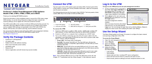
Installation Guide ProSecure™ Unified Threat Management (UTM) Appliance Models UTM5, UTM10, UTM25, UTM50, and UTM150Thank you for selecting NETGEAR products.Follow the instructions in this installation guide to connect the UTM using a single WAN interface, to use the Setup Wizard to configure the basic network and scanning settings, and to register the UTM and activate its licenses.The UTM models differ in the number of LAN and WAN ports that they provide. For information about the different models and about how to configure other options such as multiple WAN settings (not applicable to the UTM 5 and UTM10), the firewall, VPN tunnels, and custom scanning, see the reference manual.You can access the reference manual from the UTM’s web management interface, through the resource CD, and from the NETGEAR support site at.Verify the Package Contents•ProSecure™ UTM appliance•AC power cable•Rubber feet (4) with adhesive backing•Rack-mount brackets (some models)•Installation guide•Resource CD•Service registration card with license keys (some models)Connect the UTMThe front panel of the UTM contains ports and status LEDs; the back panel of theUTM contains a console port, Factory Defaults reset button, cable lock receptacle,and AC power connection.The following figure shows the front panel of the UTM150. The front panels of othermodels differ only in the number of LAN and WAN ports.To connect the UTM:1.Connect a WAN port to a cable or DSL modem, satellite dish, wireless ISPradio antenna, or other WAN device that has an active WAN connection.2.Connect a LAN port to a computer that is configured as a DHCP client.3.Turn on the UTM by connecting one end of the AC power cable to the ACreceptacle on the back panel of UTM and the other end to a power outlet. Afterabout 1 minute, verify the following:•Power LED. The Power LED is solid green.•Test LED. The amber Test LED is lit. The Test LED turns off when theinitialization process is completed, approximately 2minutes after you haveturned on the UTM.•WAN LED. The left LED of the connected WAN port is lit. If it is not, makesure that the Ethernet cable is securely attached to the WAN device and theWAN port, and that the WAN device is on.•LAN LED. The left LED of the connected LAN port is on. If it is not, makesure that the Ethernet cable from the computer to the UTM is securelyattached at both ends, and that the computer is on.Note:If any of these LEDs are not lit, or if the Test LED does not turn off, seeChapter 12, “Troubleshoot and Use Online Support,” of the reference manual.1.Power LED (green)2.Test LED (amber)B portN ports and LEDs5.DMZ LED for LAN port 46.WAN ports and LEDsLog In to the UTMTo log in to the UTM and access its web management interface:1.On the computer that is connected tothe UTM, enter https://192.168.1.1 inthe address field of a browser. TheNETGEAR Configuration ManagerLogin screen displays in the browser.2.Enter admin for the user name andpassword for the password, and clickthe Login button.The web management interfacedisplays.After 5 minutes of inactivity (the defaultlogin time-out), you are automaticallylogged out. You can change the login time-out by selecting Users > Users todisplay the Users screen and modifying the admin user settings.Use the Setup WizardThe Setup Wizard guides you through 10 screens to configure the basic networkand scanning configuration of the UTM.To access the Setup Wizard:1.Open the web management interface.2.Select Wizards.3.Select the SetupWizard radio button.4.Follow the SetupWizard to configurethe following settings:•LAN settings•WAN settings•System date and time, including NTP server configuration•Email and web services (that is, protocols) and ports to scan•Email security (antivirus settings) and scan exceptions based on sizehttps://192.168.1.1December 2012NETGEAR and the NETGEAR logo are registered trademarks of NETGEAR, Inc. in the United States and/or other countries. Other brand and product names are trademarks or registered trademarks of their respective holders. Information is subject to change without notice. © NETGEAR, Inc. All rights reserved.Intended for indoor use only in all EU member states, EFTA states, and Switzerland.•Web security (antivirus settings) and scan exceptions based on size•Web categories to be blocked•Email notification•Scan engine and signatures update settings5.Click the Apply button to save your changes.The UTM reboots. If the IP address of your computer is now on a differentsubnet, restart the computer to refresh its network settings so you can log in to the UTM again.Note:For detailed steps about how to configure the UTM by using the Setup Wizard, see Chapter 2, “Use the Setup Wizard to Provision the UTM in Your Network,” of the reference manual.Register the UTM and Activate the Licenses To receive threat management component updates and use telephone support, you need to register your UTM with NETGEAR. You might have purchased the UTM with a 1- or 3-year license. The UTM also comes with four 30-day trial licenses:•Web protection•Email protection•Support and maintenance•Application control and IPSIf your UTM is unregistered, you can use the 30-day trial period for all four types of licenses to perform the initial testing and configuration.Activating the licenses initiates their terms of use. Activate the licenses only when you are ready to start using the UTM. The 30-day trial licenses are revoked once you activate the purchased licenses.To register the UTM and activate the trial or purchased licenses:1.Make sure that the UTM has Internet access.2.Open the web management interface.3.Select Support > Registration. The Registration screen displays.4.Enter one of the license keys in the Registration Key field.plete the fields in the Customer Information and VAR Information sectionsof the screen.6.Click one of the following buttons:•Trial. Activates a trial license and registers the UTM with the NETGEARregistration and update server.•Register. Activates a purchased license and registers the UTM with theNETGEAR registration and update server.7.If necessary, repeat Step 4 and Step 6 for additional license keys.After the registration and activation are complete, the Registration screenshows the license keys and their expiration dates:Electronic Licensing OptionIf you have purchased the UTM with a 1- or 3-year license, you might be able to usethe electronic licensing option. When the UTM is connected to the Internet, youneed to enter only your customer information and optional value-added reseller(VAR) information on the Register screen but do not need to enter the licensenumbers. When you click the Register button, the UTM automatically downloadsand activates the license keys because the serial number of the UTM is linked to thelicense.If you have purchased a license from a VAR (either directly or over the web) afterpurchase of the UTM, the VAR should email you the license keys or provide them toyou in another way. To register and activate the license keys, follow the regularregistration procedure as explained in the previous section (see steps 1–7).Online Documentation and ResourcesFor extensive information about configuring and using your UTM, see the referencemanual, which you can access from or from theweb management interface.To access online documentation and resources:1.Open the web management interface.2.Select one of the following:•To view the reference manual, select Support > Documentation.•To view the product support page, select Support > Knowledge Base.Technical SupportVisit for product updates and web support.For the complete EU Declaration of Conformity, visit/app/answers/detail/a_id/11621/.NETGEAR recommends that you use only the official NETGEAR supportresources.。
iControl RC1e 5.3 用户指南说明书

R e a c t i o n C a l o r i m e t e riControl RC1e ™5.3Release NotesDear Customer,Thank you for purchasing iControl RC1e 5.3, the simply powerful software package for the METTLER TOLEDO RC1e Reaction Calorimeter. Everything you need to install and run iControl RC1e 5.3 is stored on the installation media (DVD-ROM or downloaded zip file).Contents of the Installation Media- iControl RC1e 5.3 Software Installer (AutoRun.exe) - iControl RC1e 5.3 Release Notes (this file) - iControl RC1e 5.3 Quick Start Guide- iControl RC1e 5.3 Installation Guide for Administrators - iControl Data Conversion Utility for WinRC experiments - iControl Mixing Guidelines- iC Data Share Microsoft ® Excel Add-in-UCB Firmware 3.4.2 for Universal Control Box (UCB) and RTCal BoxInstallation Guide and System RequirementsPlease install iControl RC1e 5.3 according to the Quick Start Guide which can be found on the installation media. This also describes the minimum PC specifications needed to install and run iControl RC1e.Tutorial Videos and Help FileWe highly recommend watching the Tutorial Videos accessible from the iControl RC1e 5.3 Start Page. These brief videos provide an excellent overview of the software and allow new users tofamiliarize themselves with iControl in minutes. For more in depth help, a comprehensive Help File is available. To access the context-sensitive Help from a specific place in the software, click in the software window and then press F1 on the keyboard.Customer SupportIf you have any questions or encounter any issues with iControl RC1e 5.3, please contact your local Account Manager or Service Engineer, or contact us at:****************** for General Support on Reaction Engineering *********for Software Supporti C o n t r o l R C 1e 5.3 R e l e a s e N o t e sFeature Comparsion TableKey features of iControl RC1e 5.3 compared with earlier versions of iControl and WinRC:i C o n t r o l R C 1e 5.3 R e l e a s e N o t e si C o n t r o l R C 1e 5.3 R e l e a s e N o t e s✓ = Supported feature ✓+ = Supported feature with enhancements X = Not supportedi C o n t r o l R C 1e 5.3 R e l e a s e N o t e sThese release notes summarize incremental changes in iControl RC1e.Enhancements for Version 5.3Easy Data Collection and Instrument ControlLive Values for qr_hf, UA and cpr TrendsU values are being extrapolated as soon as a first U value is available. The constant availability of U allows the live calculation of the qr_hf, UA and cpr trends and hence the availability of live heat data. Note that the trend values may change as soon as a new U value gets calculated. In case highly accurate live heat data is required, RTCal technology will provide better data.New ‘Setpoint by expression’ Mode for UCB PID C ontrollerThe Control PID Loop operation for the UCB (Universal Control Box) has an additional option that now allows the setpoint to be determined by an expression.Intuitive Data Analysis and VisualizationNew Version of iC SafetyiC Safety is a crucial tool for evaluating the thermal risks of a chemical reaction at industrial scale for use by novice, as well as advanced users. iC Safety summarizes key safety information in an easy-to understand graphical format and provides access to detailed safety data for expert users. In the new 5.3 version, the user interface has been simplified to enable a better user experience for all userlevels. In addition, functionality has been added to evaluate multiple dosings or reactions at one time by dragging a single integral over several dosings or reactions.Tr Information Available in U and cpr TablesThe U and cpr tables contain a new column with the Tr value that was current at the time of the corresponding U or cpr determination.‘Save as’ Menu Item AddedUnder the ‘File’ menu, a new item ‘Save as’ has been added allowing the user to store a copy of the current experiment, including all of its data, at any time.Tr, Tj, R, Vr and Mr Values for Every Operation and Annotation AvailableIn the recipe contained in the new report designer, you may show Tr, Tj, R, Vr or Mr values for every operation or annotation. Use the 'Select Columns' icon on the Recipe item to choose which columns to display.i C o n t r o l R C 1e 5.3 R e l e a s e N o t e sMoving Tabs into Different Screen AreasIn previous versions of iControl, the tabs available for each viewer pane were fixed. For example, it was not possible to see the ‘Trends’ at the top and the ‘Procedure’ at the bottom. iControl 5.3 gi ves you unlimited freedom to move tabs into different screen areas and customize the screen as you prefer it. Simply grab the tab and drag it to the new pane that you wish it to be displayed in. The system will remember the tab locations for each experiment mode (Design, Run, Analyze).Quick Reporting and Data ExchangeReport Designer Available as Part of ExperimentiControl 5.3 features an easy to use WYSIWYG (what you see is what you get) Report Designer allowing users to create experiment reports that f it company’s standards. A new ‘Report’ tab is included as part of every iControl 5.3 experiment which by default includes all the significant data from an experiment. The user can easily customize this report from within iControl by simply dragging & dropping items such as Trend Graphs or the Experiment Recipe. Users can also add experiment specific text or images from other sources to the report before, during, or after the experiment completes. The resulting report can then be exported to Microsoft ® Word ® so it can be easily shared with others.Support for iC Data CenterThis version of iControl RC1e supports iC Data Center 5.2. With iC Data Center, all data generated on any supported instrument or software (EasyMax, OptiMax, iC IR, iC FBRM or iControl) isautomatically captured and stored in a central file share. A Microsoft ® Word ® report and Excel ® file are then prepared automatically and stored in the same location. The data is shared by sending an email to the user containing a link to the files.For more information about iC Data Center, visit /icdatacenter .Integration with iC Data Share Microsoft ® Excel ® Add-inThe iC Data Share software application is an add-in module for Microsoft ® Excel ® that allows real-time sharing of data. iC Data Share can pull data from a running iC or iControl experiment intoMicrosoft ® Excel ® so that it can be used in calculations, and any resulting values can be sent back to iControl and trended. This provides an easy way to integrate live data from other third party applications that support Microsoft ® Excel ® interfaces.The installer for the iC Data Share add-in is provided in a separate folder on the iControl 5.3 Installation DVD or downloaded zip file. iC Data Share can be installed on the same computer as iControl 5.3 or on a different computer as long as it has network access to the iControl system.CompatibilitySupport of Windows 8 and 64-bit Operating Systems AddediControl RC1e now fully supports Microsoft ® Windows ® 8/8.1 and all 64-bit versions of the Microsoft ® Windows ® 7 and 8 operating systems.i C o n t r o l R C 1e 5.3 R e l e a s e N o t e sKnown Issuesi C o n t r o l R C 1e 5.3 R e l e a s e N o t e si C o n t r o l R C 1e 5.3 R e l e a s e N o t e si C o n t r o l R C 1e 5.3 R e l e a s e N o t e si C o n t r o l R C 1e 5.3 R e l e a s e N o t e s Enhancements for Version 5.0Easy Data Collection and Instrument Control Chemistry Table The chemistry table is a completely new integrated feature module that allows the user to easily define the chemical reaction and calculate the amounts required. The chemistry table contains an intelligent calculation engine that is directly linked to the chemical database and that determines the required amounts based on the given stoichiometric factors and ratios. The calculated amounts are directly linked to the dosing table of the experiment. Improvement of RTCal Calibration and Adjustment Procedure RTCal is a unique METTLER TOLEDO calorimetry technology which allows an online measurement of heat data without the need for an experiment calibration. In order to achieve the optimal reliability of the measurement it is advisable to have the heat flux sensor bands adjusted by a METTLER TOLEDO field service engineer upon installation of the system and then to calibrate the sensors on a regular basis. The wizard to run the adjustment and calibration were improved extensively so the procedure is as easy and robust as possible. Reflux Factor Estimation with RTCal License The operation “HF Qreflux factor determination” has been renamed to “Qreflux factor determination” since this operation is now also available for users with an RTCal license. In previous versions thisoperation was restricted to users with a Heat Flow license.New Mathematical Functions for User Defined Trends (UDTs)Besides the four arithmetic functions ( + - * / ), an additional six mathematical operations have been added to UDTs: first derivative, averaging, natural logarithm, logarithm, n th root, and exponentiation. New Trend for Elapsed Time to Be ShownA new Elapsed Time trend reflects the time passed since the start of the experiment.Global Settings for Trends and Y-AxisThe “Save current settings” functionality for the trends tab has been enhanced. It is now possible to define global trend view settings that are applied to every new experiment. The user can define the trends to be shown including the name, color, line width, line style and the settings for the y-axis like the minimum and maximum value, auto scaling, logarithmic and show grid properties etc. These settings are kept persistent and valid for every system user.i C o n t r o l R C 1e 5.3 R e l e a s e N o t e s Copying User Defined Trend (UDT) During Run-TimeIn the previous software version, when copying and pasting a UDT into a running experiment, the UDT immediately became read-only. With the current release the user has the ability to edit a user defined trend when pasting it into a running experiment. Selectable Unit Check for User Defined Trend By default the option “Enforce units compatibility” is selected. This means, the editor checks that all terms of the expression have compatible units. If you select “Ignore units”, this check is omit ted and the resulting units can be defined manually: Visibility of Set Value for Mass During Dosing with UCB Equipment Beneath the end value, the actual mass and the dosing rate, now the set mass is displayed so it is available at first glance on the live equipment picture of the dosing controller. Visibility of Temperature Control Parameters (P&I) The T r control parameters P (Amplification) and I (Reset Time) are now visible during runtime in the tooltip for the reactor. Within the start operation of an experiment the setting of the P parameter can be viewed during runtime and can be adapted to either an organic or an aqueous reaction mass during the design phase of an experiment. Change of RD10 Dosing Rate During Running Dosing OperationThe dosing rate of a running RD10 dosing loop can be changed on the fly by entering a new value in the equipment overview (same behavior as for UCB dosing controller).Dosing Profile Based on Arbitrary ExpressionIt is now possible to perform a dosing task against any available trend or against a user defined trend.Completion of Manual Dosing without User InteractionThe user can now decide within the Manual Add task whether or not a user interaction oracknowledgement is required to complete the operation.Play an audible alert during Acknowledge MessageIt is now possible to insert an operator message at any point of the procedure that will play anaudible alert. This alert can be a custom wave or mp3 file and can be configured to be repeated until the user acknowledges the message.i C o n t r o l R C 1e 5.3 R e l e a s e N o t e s New Thermostat Mode to Hold Actual T r or T j ValueThis useful option for the “Heat/Cool” operation will keep the actual temperature value (T r or T j mode) constant. This new set temperature is visible in the experiment event log. Option to Switch Off Overfill Warnings during Whole Experiment During the setup of the reactor (double click on the reactor in the equipment setup) a new option “Warn if reactor contents exceeds maximal volume” has been added. This option is by default switched on – but can be deactivated by the user. Intuitive Data Analysis and Visualization New Version of iC Safety iC Safety is a crucial tool for evaluating the thermal risks of a chemical reaction at industrial scale for use by novice, as well as advanced users. In addition, iC Safety summarizes key safety information in an easy-to understand graphical format and provides access to detailed safety data for expert users. In its new version 5.3, this D2i (Data to Information) module provides an even more enhanced interface and improved functionality such as the calculation of TD24, criticality classes, analysis of multiple reactions and the ability to take snapshots for the comparison of results. Watch the iC Safety tutorial video for an introduction to this very powerful tool. Custom Offset for Int(qr_rtc) The integration of qr_rtc now uses the real baseline. In previous versions the integration was alwaysdone from zero.Basepoint Proportionality Can Be Defined and Kept PersistentThe default basepoint proportionality for cpr, Reflux Factor, U and Vv can now be changed and kept persistent for eac h experiment and each user within the “Options” window of iControl.The Points of a Manual Baseline Can Now Be Edited EasilyFor a baseline or a baseline with integral it is now possible to select the type “Manual”. Using this type makes it possible to add or edit baseline-points using drag-and-drop. Alternatively it is also possible to enter the exact values for changed or added points within a separate window. Option to Decide if Averaged Dosing Rate (qdos) Should Be UsedDuring the determination of the terms for qr_hf and qr_rtc, it can be decided if an averaged derivation for the dosing rate (qdos) should be used or not.The Cpi Values of UCB Sensors Are Considered for CalculationsWhile setting up a UCB sensor it is now possible to define Cpi values with respect to a specificreactor type. Using the option “Linked to” allows the user to link the selected sensor to the Cpi valuesi C o n t r o l R C 1e 5.3 R e l e a s e N o t e s of another sensor already defined in the equipment database. Simply choose the sensor to link to from a dropdown list and the Cpi values of this sensor will be used.Option to Compensate qc During Calculation of qr_hf and/or qr_rtc While defining the terms for calculating qr_hf and qr_rtc, the user can decide if qc (the heat flow due to a calibration heater) should be compensated or not. Quick Reporting and Data Exchange Print Functionality Added to Many Screens The option to send a screenshot directly to a printer has been added to many of the displays within iControl. This functionality can be used to print a screenshot on paper or to transfer a screenshot to an ELNB (electronic laboratory note book) provided this is installed on your system as a printer. Printable Sensor History Report Within iControl RC1e 5.0 it is now possible to print a detailed sensor history report, regardless of whether the sensor is connected to the RC1e itself or to a RD10, RTCal or UCB box. The report contains offset and slope data and the date and type of the last adjustment for each sensor. New Functionality for the Chemical Database The chemical database has been enhanced with some new functionality to improve its usability: ∙ Chemicals can now be assigned to groups – for example, chemicals can be structured intoacids, bases, solvents, catalysts, etc.∙ Using the new “Comments” field , specific data in relation to a chemical (or a specific batch of thischemical) like the purity or the source of supply, can be stored together with the physical or chemical properties.∙ The import and export behavior for chemicals has been improved and is now easier and moreintuitive.Chemical Database Is Shared between All iControl Versions and iC KineticsThere is no need to manage more than one version of the chemical database on one computer if working with different versions of iControl or in combination with iC Kinetics. All applications share the same chemical database and access the same physical and chemical data.CompatibilitySupport of Windows Vista 64-bit and Windows 7 AddediControl now fully supports the 32-bit versions of Windows Vista and Windows 7 as well as Windows XP SP3. Additionally, iControl Office provides support for 64-bit systems.i C ontrolR C1e5.3Rel e aseN ote s Updated Equipment DatabaseThe equipment database that the user specifies and selects his METTLER TOLEDO equipment from, like reactors, covers and stirrers, has been updated and now contains the latest equipment offered by METTLER TOLEDO.。
Windows Server 2012 R2 快速入门指南说明书

For more information about the installation options, what is included with each option, how to switch between them, and related features such as the Minimal Server Interface and Features on Demand, see Windows Server Installation Options at /fwlink/p/?LinkId=242140.
Automated Installation You can automate Windows Server installation by using the tools and documentation in the Windows Assessment and Deployment mating deployment eliminates the need for any user interaction during installation. In addition, you can configure different options within the operating system, such as Internet Explorer settings and network settings.
The two installation options are available for most Windows Server editions. Not all server roles and features are available in all editions. For details about the roles and features available in each Windows Server edition, see /fwlink/p/?LinkId=251499
Fusion

®FUSION® Panel-Stereo InstallationInstructionsproduct box for product warnings and other important information.This device must be installed according to these instructions. Disconnect the vehicle's or vessel's power supply beforebeginning to install this product.may cause permanent hearing loss. The volume is typically too loud if you cannot hear people speaking around you. Limit the amount of time you listen at high volume. If you experience ringing in your ears or muffled speech, stop listening and have your hearing checked.Always wear safety goggles, ear protection, and a dust mask when drilling, cutting, or sanding.NOTICEWhen drilling or cutting, always check what is on the opposite side of the surface.It is strongly recommended that you have your audio system installed by a professional installer to ensure optimum performance.You must read all installation instructions before beginning the installation. If you experience difficulty during the installation, go to for product support.What's in the Box•FUSION Panel-Stereo•Stereo trim•Six 6-gauge, self-tapping stainless steel screws•Power wiring harnessTools Needed•Electric drill•Drill bit (size varies based on surface material)•Phillips screwdriver•Wire strippers•Crimping tool•Electrical tape•Appropriate saw or utility knife to cut surface material •Marine sealant (optional)NOTE: For customized installations, additional tools and materials may be needed.Mounting ConsiderationsSelecting the correct mounting location is critical to optimize the performance of the stereo. FUSION stereos are designed to perform in the widest possible range of mounting locations, but the more you plan the installation, the better the stereo's sound will be.NOTE: If you install the optional mounting spacer, you must use the six black screws supplied with the mounting spacer to mount the stereo to the mounting spacer.•Using the included screws, this stereo can be flush mounted in a surface with a depth of at least 50 mm (2 in.)•Using an optional spacer (sold separately), this stereo can be mounted directly on a flat surface.•To ensure water does not enter between the stereo and mounting surface, you should use marine sealant whenmounting the stereo.•For the best performance, the stereo should not be mounted low in the vehicle or vessel. Sound travels in the direction in which the stereo is facing. When the stereo is mounted low, the sound quality and volume are not ideal.•For the best seal, you should select a flat mounting surface.•The mounting location must avoid potential obstacles, such as fuel and hydraulic lines and wiring.•The cable should have a drip loop to allow water to drip down off the cable and avoid damaging the stereo.•The Panel-Stereo should be mounted in a location that is not exposed to direct sunlight for prolonged periods of time. The Panel-Stereo Outdoor can be mounted in a location that is exposed to direct sunlight for prolonged periods of time.•To avoid interference with a magnetic compass, the stereo should not be installed closer to a compass than thecompass-safe distance value listed in the productspecifications.•You should protect the stereo wires from sharp objects and always use rubber grommets when wiring through panels.•You should protect all terminals and connections from grounding and from each other. Failure to do so could result in permanent damage to the audio system and void theproduct warranty.Mounting the StereoBefore mounting the stereo, you must choose a location where there is enough clearance behind the mounting surface. Refer to the side view drawings for clearance information.If necessary, you can purchase a spacer (not included) to install the stereo directly onto a flat surface.Before mounting the stereo, you must choose a location following the guidelines above.1Trim the template and make sure it fits in the selected location.2Secure the template to the selected location.3Using a drill bit appropriate for the mounting surface, drill a hole inside the dashed line on the template to prepare themounting surface for cutting.4Using a jigsaw or rotary tool, cut the mounting surface along the inside of the line on the template.5Place the stereo in the cutout to test the fit.6If necessary, use a file and sandpaper to refine the size of the cutout.7After the stereo fits correctly in the cutout, ensure the mounting holes on the stereo line up with the pilot holes on the template.8If the mounting holes on the stereo do not line up, mark the new hole locations.9Using an appropriately sized drill bit for the mounting surface and screw type, drill the holes.10Remove the template from the mounting surface.11Make the necessary wiring connections (Connector Identification, page 2).12Place the stereo in the cutout .December 201813If there is a concern that water may enter the mountingsurface around the edges of the stereo, apply marine sealant around each of the screw holes and between the stereo and the mounting surface (optional).NOTICEDo not apply grease or lubricant to the screws whenfastening the stereo to the mounting surface. Grease or other lubricants can cause damage to the stereo housing.14Secure the stereo to the mounting surface using the includedscrews , or screws appropriate for the depth of the mounting surface.NOTE: Do not over tighten the screws, especially if the mounting surface is not flat.15Press the trim firmly onto the stereo until all of the pins snap into place.Connector IdentificationConnecting to PowerWhen connecting the stereo to power, you should connect it through the ignition or another manual switch.If it is necessary to extend the power and ground wires, use14 AWG (2.08 mm 2) wire. For extensions longer than 1 m (3 ft.),use 12 AWG (3.31 mm 2) wire.1Route the red power wire to the ignition or another manual switch , and route the black ground wire to the battery.2If necessary, route a wire between the switch and the battery .3Route the wiring-harness plug to the stereo.Do not connect the wiring harness to the stereo until after all of the bare wire connections have been made.4Connect the black wire to the negative (-) battery terminal.5Connect the red power wire to the ignition or another manual switch, and connect the switch to the positive (+) battery terminal if necessary.6Connect the wiring harness plug to the stereo.Stereo InformationRegistering Your FUSION Panel-StereoHelp us better support you by completing our online registration today.•Go to .•Keep the original sales receipt, or a photocopy, in a safe place.Cleaning the StereoNOTE: This stereo is rated IP65 for protection in harsh environments. It is not designed to withstand high pressure water spray, which may occur when you wash down yourvehicle or vessel. Failure to carefully spray-clean the vehicle or vessel may damage the product and void the warranty.NOTICEDo not use harsh or solvent-based cleaners on the stereo. Using such cleaners may damage the product and void the warranty.1Clean all salt water and salt residue from the stereo grille witha damp cloth soaked in fresh water.2Use a mild detergent to remove a heavy buildup of salt or stains.Dimension DrawingsRear ViewDimensions are shown without the trim attached.Side ViewSpecificationsIngress protection rating*IEC 60529 IP65Dimensions with trim (W × H × D)344 x 155 x 50 mm (13.54 x 6.1 x 1.97 in.)Weight1.15 kg (2.54 lb.)Operating temperature range From 0° to 50°C (from 32° to 122°F)Long-term storage temperature rangeFrom -20° to 70°C (from -4° to 158°F)Bluetooth wireless rangeUp to 10 m (33 ft.)ANT wireless rangeUp to 3 m (10 ft.)Input voltage From 10.8 to 16.0 Vdc Current (max.)10 A Fuse10 A Line output level (max.) (peak to peak)5.5 V Aux. input level (typical) RMS1 V*IP rating does not include rear connectors.Compass-Safe DistancesAll stereo speakers contain magnets which may causeinterference with instruments on your vehicle or vessel. The size of the magnet used in the stereo speakers affects how much interference the stereo speakers may cause.Interference can cause deviations and variations in the readings of sensitive navigational equipment, such as magneticcompasses. These deviations can cause inaccuracies or offsetsin the readings, but will not harm the equipment. To alleviate the deviations, adjust the compass for the deviation following the manufacturer's instructions or move the stereo away from the navigational equipment. After moving a source of interference, you may need to recalibrate the compass.If you are navigating solely by a magnetic compass, useextreme caution to place the stereo far enough away from the compass to avoid causing deviations in the readings.To avoid deviations to navigational equipment, position the stereo so it is separated from the navigational equipment by at least the distances listed in the table below.TroubleshootingBefore you contact your FUSION dealer or service center, you should perform a few simple troubleshooting steps to help diagnose the problem.If the FUSION stereo has been professionally installed, you should contact the installer so a technician can assess the problem and advise you about possible solutions.The audio is distorted•Verify that the panels surrounding the stereo on the vehicle or vessel are not rattling.•Verify that the source volume is not too loud, and reduce the volume if necessary.•Verify that all RCA connections are in good condition, and the connectors are insulated from each other.•Verify that all cables are properly attached.© 2018 Garmin Ltd. or its subsidiariesGarmin , the Garmin logo, FUSION , the Fusion logo, and True-Marine ™ are trademarks of Garmin Ltd. or its subsidiaries, registered in the USA and other countries. These trademarks may not be used without the express permission of Garmin.。
win8.1rtm是什么意思
win8.1rtm是什么意思都说微软更新换代很快,继win8推出win8.1升级版之后,,微软又推出了新的升级方案,那就是win8.1升级Win8.1 Update RTM,那么win8.1 rtm是什么意思呢?下面跟着店铺来一起了解下吧。
win8.1 rtm详解RTM版的英文全称为:Release T o Manufacturing(发布到制造),windows操作系统在零售商店正式上架前,需要一段时间来压片,包装和配销。
所以程序代码必须在正式发行前一段时间就要完成,这个完成的程序代码叫做Final.Code.程序代码开发完成之后,要将母片送到工厂大量压片,这个版本就叫做RTM版。
所以说,RTM版的程序和正式版一样.Windows 8.1 RTM比Win8增加了哪些功能安装Win 8.1 的安装和之前 Win 8 的安装无论是方法还是过程都是一样的,不同的地方仅仅在于安装过程如果选择自定义设置可以提前看到一些 Win 8 所没有的功能。
锁屏Win8.1 新增了在锁屏界面上播放幻灯片功能,并且默认为开启。
经常在自己电脑里存有 18+only 图片的童鞋注意了,下图为一个使用Win8.1 Preview 版的童鞋离开座位时的锁屏界面(处理后照片),那天路过该电脑前的我和我的小伙伴们都惊呆了。
另外 Win8.1 还是支持将桌面壁纸同时设为锁屏壁纸,并在个性化设置中增加了更多的颜色和背景图。
开始按钮被无数人吐槽后在 Windows 8.1 中微软终于又将“开始按钮”加了回来,然后又引起了无数人吐槽。
因为加上的那个“开始按钮”普通左键点击依旧起到的是之前Win8 中左下角触发传统桌面与Metro 界面切换的功能,唯有右键才有一堆很难识别的功能菜单,并不是大多数人想要的,还不如不加。
三个状态下的“开始按钮”开始屏幕可以隐藏在 Win 8.1 RTM 中开始屏幕最大的改进莫过于可以选择跳过了,右键任务栏,在弹出的任务栏和导航属性菜单中的第二个Tab标签中可以看到多了开机后直接转到传统桌面而不是之前Win8 强制性先跳转到开始屏幕。
IBM TRIRIGA 和 IBM TRIRIGA 应用程序平台快速入门指南说明书

IBM TRIRIGA and IBM TRIRIGA Application PlatformQuick Start GuideVersion 10.8.0 and 3.8.0This guide introduces IBM® TRIRIGA® version 10.8.0 and IBM TRIRIGA Application Platform version3.8.0, provides a link to a list of prerequisite software, gets you started with a typical installation, andprovides a roadmap to other important information.Note:IBM TRIRIGA 10.8.0 and IBM TRIRIGA Application Platform version 3.8.0 Licensed Materials - Property of IBM. © Copyright IBM Corp. 2020. U.S. Government Users Restricted Rights - Use, duplication ordisclosure restricted by GSA ADP Schedule Contract with IBM Corp.IBM, the IBM logo, and ® are trademarks or registered trademarks of International BusinessMachines Corp., registered in many jurisdictions worldwide. Other product and service names might be trademarks of IBM or other companies. A current list of IBM trademarks is available on the Web at"Copyright and trademark information" (/legal/copytrade.shtml).About this taskProduct overviewThe IBM TRIRIGA solution combines applications in an integrated package that is designed to automate, streamline, and manage all processes related to the workplace, including people, locations, and assets.With the combination of interrelated functions provided in one solution, organizations create synergies, reduce operational costs, support centralized control, enhance communication, and improve processefficiency throughout the enterprise.The IBM TRIRIGA Application Platform product provides organizations with graphical and configuration tools to rapidly configure applications and extend the use and value of the IBM TRIRIGA applications. The standards-based technology, interfaces, and a workflow process engine drive interoperability with critical business systems. The n-tiered architecture and performance benchmarks of IBM TRIRIGA Application Platform provide key tools and system configuration guidance to achieve enterprise-class scalability.Procedure1.Access the software and documentationTo download your product from IBM Passport Advantage®, follow the instructions in the IBM TRIRIGAand IBM TRIRIGA Application Platform download document (/support/pages/node/6373624).Before you install the product, read Installing IBM TRIRIGA Application Platform (/support/knowledgecenter/SSHEB3_3.8/com.ibm.tap.doc/ins_overview/t_ctr_install_ibm_tap.html).Review the release notes for this product in the IBM TRIRIGA Release Notes for 10.8.0 and 3.8.0(/support/pages/node/1275142). The release notes contain the latest information thatis relevant to the installation of this product.For complete documentation, see the IBM TRIRIGA 10.8.0 Knowledge Center (/support/knowledgecenter/SSFCZ3_10.8/com.ibm.tri.doc/product_landing.html) and the IBM TRIRIGA Application Platform 3.8.0 Knowledge Center (/support/knowledgecenter/SSHEB3_3.8/ com.ibm.tap.doc/product_landing.html).2.Plan the installationInstall the IBM TRIRIGA solution and the IBM TRIRIGA Application Platform product on a server thatcontains a supported Java™ application server.IBM TRIRIGA and IBM TRIRIGA Application Platform 1For information about the hardware, software, and network requirements for the product, see theCompatibility Matrix for IBM TRIRIGA Products (/support/pages/node/1283650).3.Install or upgrade the productTo perform a new installation, follow these steps.a.Review the software requirements.b.Install and configure the database. (Oracle, Microsoft SQL Server)c.Install and configure the application server. (IBM WebSphere® Application Server, Oracle WebLogicServer, JBoss Application Server)d.Select the IBM TRIRIGA installer for your operating system.e.Select New install.f.Answer the installation questions as appropriate for your environment. After you click Next, theinstaller configures the application server and the database.g.If you are using WebLogic or WebSphere, and if the installer fails to configure the application server,follow the manual steps in the Install Guide as appropriate for your environment.h.After installation is complete, review the configuration settings in the properties files and set themas appropriate for your environment. Also, copy your license files into the [tririga_root]\config\licenses directory.To upgrade from a previous version, follow the instructions in Upgrading (/support/knowledgecenter/SSHEB3_3.8/com.ibm.tap.doc//pdfs_wiki/Upgrading.pdf).What to do nextMore informationAfter you install the product, see the product documentation to learn more about the product.For more information, see the following resources.•IBM TRIRIGA 10.8.0 Knowledge Center (/support/knowledgecenter/SSFCZ3_10.8/com.ibm.tri.doc/product_landing.html)•IBM TRIRIGA Application Platform 3.8.0 Knowledge Center (/support/knowledgecenter/ SSHEB3_3.8/com.ibm.tap.doc/product_landing.html)•Product support (/support)2 IBM TRIRIGA and IBM TRIRIGA Application Platform。
- 1、下载文档前请自行甄别文档内容的完整性,平台不提供额外的编辑、内容补充、找答案等附加服务。
- 2、"仅部分预览"的文档,不可在线预览部分如存在完整性等问题,可反馈申请退款(可完整预览的文档不适用该条件!)。
- 3、如文档侵犯您的权益,请联系客服反馈,我们会尽快为您处理(人工客服工作时间:9:00-18:30)。
Prepare for installationBefore you install the RTM:•Verify it is compatible with its corresponding frontmodule. Refer to the documentation for the RTM.•Make sure you are adequately grounded beforehandling the RTM, as described in the previoussection, Before you begin.•The RTM may be mechanically keyed to prevent itsaccidental insertion into an incompatible frontmodule. Be careful to note any special keyingbefore inserting the RTM.•Determine which front node slot in the shelf youplan to use for the front module. The RTM will beinstalled in the corresponding rear slot. Forexample, if you intend to install the module in frontphysical slot number 3, install the RTM in rearphysical slot number 3.•Remove the airflow management panel, if present,from the back of the shelf where the RTM is to beinstalled.•Install any components not included with the RTM,such as a hard disk drive and SFP transceivers. Installation Guide© 2006–2012 by RadiSys Corporation. All rights reserved.Radisys is a registered trademark of RadiSys Corporation. AdvancedTCA, ATCA, and PICMG areregistered trademarks of PCI Industrial Computer Manufacturers Group. All other trademarks, registered trademarks, service marks, and trade names are the property of their respective owners.*007-03345-0002*REAR TRANSITION MODULEThis document describes how to install and set up a Rear Transition Module (RTM) in an AdvancedTCA® (ATCA®) shelf. The RTM provides additional I/O connections to the front module through the back side of the shelf.The RTM attaches to the shelf using standard Zone 3 connectors, as shown in Figure 2 on page 4. These connectors receive power from the shelf for the RTM’s rear panel I/O circuitry and also provide signaling and management connections.Before you beginTo ensure all safety precautions are followed during installation and setup, review the Safety Information document on the downloads page for the RTM at /downloads.Obey ESD proceduresW ARNING! Obey the electrostatic discharge (ESD) procedures described at /esd when you install the product. Electrostatic discharge can cause permanent damage to static‐sensitive components in this product.Important ESD procedures include:•Keep the product in its ESD shielding bag until a step tells you to remove it.•Put on a grounded wrist strap before you move near or touch the product.•Install the product only in a grounded work area.Install SFPsSome RTMs have sockets that accept SFP (small form‐factor pluggable) transceiver modules,which provide external connections to Ethernet interfaces. The sockets are typically located onthe face plate of the RTM. Standard RTM configurations are shipped with SFP filler plugs installedto protect the internal components of the RTM.For a list of tested and qualified transceivers, see the Component Compatibility Report in theAdvancedTCA downloads section of the RadiSys Web site at /downloads.Transceiver installation Figure 1. Transceiver insertionFigure 1 shows the correct orientation for inserting Array an SFP transceiver. The transceiver may vary inappearance, but the same insertion guidelinesshould be used.1.Obey the ESD procedures in Before you beginon page 1, making sure you are adequatelygrounded.2.Remove the RTM and the transceivers fromtheir antistatic bags.3.On the RTM face plate, remove the filler plugsfrom the sockets where the transceivers will beinstalled. For sockets not being used, keep thefiller plugs in place.4.Make sure the latch on the cable end of thetransceiver is closed. This makes the SFP snapinto position when it is inserted into the socket.5.Hold the transceiver near the cable end andturn the connector side to the correct positiondepending on the RTM orientation:•If the RTM is vertical, turn the transceiver sothe connector side is on the right.•If the RTM is horizontal, turn the transceiver so the connector side is down.6.Insert the connector end of the transceiver into the socket.7.Once inserted into the socket, carefully slide the transceiver until its connector is fully seatedand the SFP snaps into position.8.Repeat the previous steps for each transceiver being installed.9.For transceivers with cable plugs installed on their cable end, keep the plugs in place until it istime to connect cables to the transceivers. The cable plugs protect the internal componentsof the transceivers from dust and foreign contaminants.Note: If an SFP needs to be removed, open the latch and pull the SFP out of the socket.Filler plug installationIf the SFP transceivers are removed, install either replacement transceivers or filler plugs toprotect the sockets, to control airflow, and to prevent electromagnetic interference.Install a hard disk driveSome RTMs can accommodate an optional hard disk drive (HDD) for additional data storagecapability. A separate HDD can be ordered from Radisys and installed onto the RTM prior toinstalling the RTM in the shelf. See the Component Compatibility Report for suitable hard diskdrives.Install the rear transition moduleThe RTM can be installed at any time, but it is easier to do so before the corresponding frontmodule is installed in the shelf. This section describes how to install the RTM before installing thefront module.1.To install the RTM in a new shelf, skip this step and continue with Step2.To add the RTM to an existing shelf, update each item in the order shown before proceedingwith the RTM installation. All updates and instructions are available from the RadiSys Website.a.Update the shelf FRU data with the FRU image file.b.Update the software on the corresponding front module to the latest version.c.Update the firmware on the corresponding front module to the latest version.2.Follow ESD precautions and make sure you are adequately grounded before handling theRTM.3.Remove the RTM from its ESD shielding bag.Figure 2. Generic RTM 4.Inspect the EMC gasket to make sure it Array is free of debris.5.Open both ejector latches on the RTM.6.Slide the RTM into the empty rear sloton the shelf. Use firm pressure to fullyseat the RTM in the backplaneconnector. Make sure the EMC gasketseals the surfaces it touches.7.Once the RTM is fully seated, carefullyclose both ejector latches at the sametime.Note: The RTM receives its power fromthe front module. If there is a powerLED on the RTM, it will not illuminateuntil the front module is installed.8.Tighten the retaining screws at the topand bottom of the RTM panel.9.Install the front module.e the shelf management software toverify the RTM and the correspondingfront module are available as resourcesand are operating correctly.Removing the rear transition moduleFigure 3. Opening ejector latches.Note: Some RTMs have two locking ejector Array latches, and others have one locking ejectorlatch and one friction latch. It is important thatthe lock is released before opening a lockingejector latch. See Figure 3 for an illustration ofthe ejector latches.To remove an RTM from the shelf:1.Release the two retaining screws.2.If one of the latches is a friction type,carefully pull the latch handle away fromthe RTM to open the latch. To open alocking ejector latch, disengage the lock bysliding the lock toward the handle torelease the catch from the shelf latch rail,then pull the handle away from the RTM.See Figure 3.3.Remove the RTM from the shelf.Where to go from hereRefer to the RTM documentation for information on how to operate and maintain the RTM, andfor detailed information on the RTM’s electrical, mechanical, and environmental aspects. In someinstances, RTM information may be found in the corresponding front module documentation. Where to get more product informationVisit the RadiSys web site at for product information and otherresources. Downloads (manuals, release notes, software, etc.) are available at/downloads.。