100GBS two-iteration concatenated BCH decoder architecture for optical communications
LTE_3GPP_36.213-860(中文版)
3GPP
Release 8
3
3GPP TS 36.213 V8.6.0 (2009-03)
Contents
Foreword ...................................................................................................................................................... 5 1 2 3
Internet
Copyright Notification No part may be reproduced except as authorized by written permission. The copyright and the foregoing restriction extend to reproduction in all media.
© 2009, 3GPP Organizational Partners (ARIB, ATIS, CCSA, ETSI, TTA, TTC). All rights reserved. UMTS™ is a Trade Mark of ETSI registered for the benefit of its members 3GPP™ is a Trade Mark of ETSI registered for the benefit of its Members and of the 3GPP Organizational Partners LTE™ is a Trade Mark of ETSI currently being registered for the benefit of i ts Members and of the 3GPP Organizational Partners GSM® and the GSM logo are registered and owned by the GSM Association
一种不确定数据流概率求和阈值查询方法[发明专利]
![一种不确定数据流概率求和阈值查询方法[发明专利]](https://img.taocdn.com/s3/m/39e18b22a7c30c22590102020740be1e640ecc4e.png)
专利名称:一种不确定数据流概率求和阈值查询方法专利类型:发明专利
发明人:陈岭,陈东辉
申请号:CN201911106844.3
申请日:20191113
公开号:CN111026784B
公开日:
20220503
专利内容由知识产权出版社提供
摘要:本发明公开了一种不确定数据流概率求和阈值查询方法,属于不确定数据流查询处理技术领域。
所述方法包括:1)初始化,包括查询参数设定和使用高斯混合模型对不确定数据流进行建模;
2)使用基于高斯混合模型性质和概率理论的过滤策略得到结果的上界或下界,从而快速做出判断;3)当过滤策略无效时,使用滑动窗口模型计算出准确的值,通过增量式计算减少计算代价。
本发明提出的不确定数据流概率求和阈值查询方法在集群监测、健康监测和智能安防等领域具有广阔的应用前景。
申请人:浙江大学
地址:310013 浙江省杭州市西湖区余杭塘路866号
国籍:CN
代理机构:杭州天勤知识产权代理有限公司
代理人:曹兆霞
更多信息请下载全文后查看。
非极大值一致 nms的工作流程

非极大值一致 nms的工作流程下载提示:该文档是本店铺精心编制而成的,希望大家下载后,能够帮助大家解决实际问题。
文档下载后可定制修改,请根据实际需要进行调整和使用,谢谢!本店铺为大家提供各种类型的实用资料,如教育随笔、日记赏析、句子摘抄、古诗大全、经典美文、话题作文、工作总结、词语解析、文案摘录、其他资料等等,想了解不同资料格式和写法,敬请关注!Download tips: This document is carefully compiled by this editor. I hope that after you download it, it can help you solve practical problems. The document can be customized and modified after downloading, please adjust and use it according to actual needs, thank you! In addition, this shop provides you with various types of practical materials, such as educational essays, diary appreciation, sentence excerpts, ancient poems, classic articles, topic composition, work summary, word parsing, copy excerpts, other materials and so on, want to know different data formats and writing methods, please pay attention!非极大值抑制(NMS)的工作流程在计算机视觉领域,非极大值抑制(NMS)是一种常用的技术,用于处理目标检测算法输出中的重叠框。
一种基于奇异值分解的双语语言过滤算法
一种基于奇异值分解的双语语言过滤算法
路海明;徐晋晖
【期刊名称】《中文信息学报》
【年(卷),期】1999(013)003
【摘要】本文提出了一种基于SVD(奇异值分解)的双语信息过滤算法,将双语文档进行了统一的表示,使得适应于单语过滤的算法可以方便地用于双语过滤,同时对文档向量进行了压缩,滤去了噪声,在应用方面,将双语过滤算法用于互联网上的个性化主动信息过滤。
【总页数】8页(P18-25)
【作者】路海明;徐晋晖
【作者单位】清华大学自动化系;清华大学自动化系
【正文语种】中文
【中图分类】TP391.2
【相关文献】
1.基于双语主题模型和双语词向量的跨语言知识链接 [J], 余圆圆;巢文涵;何跃鹰;李舟军
2.基于局部优化奇异值分解和K-means聚类的协同过滤算法 [J], 尹芳; 宋垚; 李骜
3.一种基于评分信息熵的融合协同过滤算法 [J], 张洁;李港
4.一种基于BP神经网络的电影协同过滤算法 [J], 宋曼
5.双语翻译过程中的译语词汇提取机制研究——基于双语语言提取理论的认知思考[J], 章琦;刘绍龙
因版权原因,仅展示原文概要,查看原文内容请购买。
如何加速马尔可夫链蒙特卡洛采样的收敛速度(十)
马尔可夫链蒙特卡洛(Markov Chain Monte Carlo, MCMC)采样是一种常用的统计学习方法,用于估计目标分布的期望和方差。
通过构建马尔可夫链,MCMC采样可以生成符合目标分布的样本,从而进行蒙特卡洛积分。
然而,MCMC采样的收敛速度通常较慢,需要大量的迭代才能得到准确的估计结果。
本文将介绍一些方法,以加速马尔可夫链蒙特卡洛采样的收敛速度。
首先,要加速MCMC采样的收敛速度,可以尝试使用更有效率的马尔可夫链转移算子。
通常情况下,Metropolis-Hastings算法是最常用的MCMC采样方法之一。
然而,Metropolis-Hastings算法的收敛速度受到链转移算子的影响。
因此,可以尝试使用更为灵活的转移算子,如Hamiltonian Monte Carlo(HMC)算法。
HMC算法通过引入动量变量,能够更加高效地探索参数空间,从而加速MCMC采样的收敛速度。
其次,除了使用更有效率的转移算子,还可以考虑对参数空间进行适当的变换,以提高MCMC采样的效率。
例如,对于高维参数空间,可以使用分块更新的方法,将参数空间分解为多个子空间,在每个子空间上进行独立的采样。
这样能够减小参数空间的维度,提高采样的效率。
另外,还可以考虑使用仿射变换等方法,对参数空间进行适当的缩放和旋转,从而使得MCMC采样更加高效。
此外,为了加速MCMC采样的收敛速度,还可以考虑使用一些自适应的方法,来调整MCMC采样的步长和方向。
例如,可以使用自适应步长的HMC算法,根据采样过程中的信息,动态地调整步长的大小,以适应参数空间的结构。
另外,还可以考虑使用自适应的方向设置方法,如NUTS算法,能够自动地调整采样方向,以更加高效地探索参数空间。
最后,为了提高MCMC采样的收敛速度,还可以考虑使用一些并行化的方法。
例如,可以使用多链并行化的方法,同时运行多条独立的马尔可夫链,从不同的初始点开始并行地进行采样,然后将不同链的采样结果进行合并,以获得更加高效的估计结果。
气泡混合轻质土使用规程
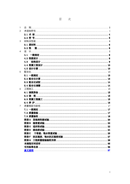
目次1总则 (3)2术语和符号 (4)2.1 术语 (4)2.2 符号 (5)3材料及性能 (6)3.1 原材料 (6)3.2 性能 (6)4设计 (8)4.1 一般规定 (8)4.2 性能设计 (8)4.3 结构设计 (9)4.4 附属工程设计 (10)4.5 设计计算 (10)5配合比 (13)5.1 一般规定 (13)5.2 配合比计算 (13)5.3 配合比试配 (14)5.4 配合比调整 (14)6工程施工 (15)6.1 浇筑准备 (15)6.2 浇筑 (15)6.3 附属工程施工 (15)6.4 养护 (16)7质量检验与验收 (17)7.1 一般规定 (17)7.2 质量检验 (17)7.3 质量验收 (18)附录A 发泡剂性能试验 (20)附录B 湿容重试验 (22)附录C 适应性试验 (22)附录D 流动度试验 (24)附录E 干容重、饱水容重试验 (25)附录F 抗压强度、饱水抗压强度试验 (27)附录G 工程质量检验验收用表 (28)本规程用词说明 (35)引用标准名录 (36)条文说明 (37)Contents1.General provisions (3)2.Terms and symbols (4)2.1 Terms (4)2.2 Symbols (5)3. Materials and properties (6)3.1 Materials (6)3.2 properties (6)4. Design (8)4.1 General provisions (8)4.2 Performance design (8)4.3 Structure design (9)4.4 Subsidiary engineering design (9)4.5 Design calculation (10)5. Mix proportion (13)5.1 General provisions (13)5.2 Mix proportion calculation (13)5.3 Mix proportion trial mix (14)5.4 Mix proportion adjustment (14)6. Engineering construction (15)6.1 Construction preparation (15)6.2 Pouring .............................................................. .. (15)6.3 Subsidiary engineering construction (16)6.4 Maintenance (17)7 Quality inspection and acceptance (18)7.1 General provisions (18)7.2 Quality evaluate (18)7.3 Quality acceptance (19)Appendix A Test of foaming agent performance (20)Appendix B Wet density test (22)Appendix C Adaptability test (23)Appendix D Flow value test.................................................................................. .. (24)Appendix E Air-dry density and saturated density test (25)Appendix F Compressive strength and saturated compressive strength test (27)Appendix G Table of evaluate and acceptance for quality (28)Explanation of Wording in this code (35)Normative standard (36)Descriptive provision (37)1总则1.0.1为规范气泡混合轻质土的设计、施工,统一质量检验标准,保证气泡混合轻质土填筑工程安全适用、技术先进、经济合理,制订本规程。
双边比对方案

双边比对方案简介双边比对方案是一种用于比较两个数据集之间相似度的方法。
在许多应用中,比如文本比对、图像匹配和基因序列比对等,双边比对方案是非常常见的。
本文将介绍双边比对方案的原理、应用和实现。
原理双边比对方案的原理基于两个数据集之间的对应关系。
通常情况下,这两个数据集具有相同的结构,但其中的元素可能有些许差异。
通过对比两个数据集中的每个元素,我们可以计算出它们之间的相似度。
在双边比对方案中,通常使用相似度度量来评估两个元素的相似程度。
常见的度量方法包括余弦相似度、欧氏距离和Jaccard系数等。
这些度量方法可以分别应用于不同类型的数据集,比如文本、图像和序列数据。
应用双边比对方案在许多领域中得到了广泛的应用。
下面将介绍一些常见的应用场景。
文本比对文本比对是双边比对方案的典型应用之一。
在文本比对中,我们可以将两个文本字符串作为输入,然后通过比对它们中的每个单词或字符,计算它们之间的相似度。
这对于实现文本搜索、拼写纠错和自然语言处理等任务非常有用。
图像匹配图像匹配是双边比对方案在计算机视觉领域中的应用。
在图像匹配中,我们可以将两个图像作为输入,然后通过比对它们中的每个像素或特征点,计算它们之间的相似度。
这对于图像检索、人脸识别和目标跟踪等任务非常有用。
基因序列比对基因序列比对是双边比对方案在生物信息学领域中的应用。
在基因序列比对中,我们可以将两个DNA或RNA序列作为输入,然后通过比对它们中的每个碱基,计算它们之间的相似度。
这对于研究基因遗传变异、进化关系和疾病诊断等任务非常有用。
实现实现双边比对方案的关键是选择合适的相似度度量和比对方法。
下面将介绍一些常见的实现方法。
自动对齐自动对齐是一种常见的双边比对方法,它通过将两个数据集中的元素进行匹配,找到它们之间的对应关系。
在自动对齐中,可以使用贪心算法、动态规划或启发式算法等来寻找最佳的匹配方式。
这种方法可以应用于文本、图像和序列等不同类型的数据集。
特征提取特征提取是一种常见的双边比对方法,它通过将两个数据集中的元素转换为数值表示,然后计算它们之间的相似度。
基于生物特征和口令的双因子认证与密钥协商协议
基于生物特征和口令的双因子认证与密钥协商协议李晓伟;杨邓奇;陈本辉;张玉清【期刊名称】《通信学报》【年(卷),期】2017(038)007【摘要】提出了一个新型的基于生物特征和口令的双因子认证与密钥协商协议.该双因子协议利用用户的生物特征以及口令信息实现安全通信,用户不需要携带智能卡.利用模糊提取技术,服务器不再保存用户生物信息,避免了服务器被攻陷用户敏感信息丢失的风险.通过服务器的公钥保护用户的认证信息,避免了基于口令的认证协议可能遭受的离线字典攻击.基于椭圆曲线计算性Diffie-Hellman假设,在随机预言模型下证明了协议的安全性.性能分析表明,所提出的协议具有较高的安全属性.%A new two-factor authenticated key agreement protocol based on biometric feature and password was pro-posed. The protocol took advantages of the user's biological information and password to achieve the secure communica-tion without bringing the smart card. The biometric feature was not stored in the server by using the fuzzy extractor tech-nique, so the sensitive information of the user cannot be leaked when the server was corrupted. The authentication mes-sages of the user were protected by the server's public key, so the protocol can resist the off-line dictionary attack which often appears in the authentication protocols based on password. The security of the proposed protocol was given in the random oracle model provided the elliptic computational Diffie-Hellman assumptionholds. The performance analysis shows the proposed protocol has better security.【总页数】7页(P89-95)【作者】李晓伟;杨邓奇;陈本辉;张玉清【作者单位】大理大学数学与计算机学院,云南大理 671000;大理大学数学与计算机学院,云南大理 671000;大理大学数学与计算机学院,云南大理 671000;北京邮电大学网络与交换技术国家重点实验室,北京 100049;中国科学院大学国家计算机网络入侵防范中心,北京 100049【正文语种】中文【中图分类】TP309【相关文献】1.基于格的用户匿名三方口令认证密钥协商协议 [J], 王彩芬;陈丽2.基于混沌映射的用户匿名三方口令认证密钥协商协议 [J], 王彩芬;陈丽;刘超;乔慧;王欢3.基于区块链技术的生物特征和口令双因子跨域认证方案 [J], 周致成;李立新;郭松;李作辉4.基于双因子认证的三方密钥协商协议 [J], 曹阳5.基于口令和智能卡的认证与密钥协商协议 [J], 洪璇;王鹏飞因版权原因,仅展示原文概要,查看原文内容请购买。
- 1、下载文档前请自行甄别文档内容的完整性,平台不提供额外的编辑、内容补充、找答案等附加服务。
- 2、"仅部分预览"的文档,不可在线预览部分如存在完整性等问题,可反馈申请退款(可完整预览的文档不适用该条件!)。
- 3、如文档侵犯您的权益,请联系客服反馈,我们会尽快为您处理(人工客服工作时间:9:00-18:30)。
100GB/S TWO-ITERATION CONCATENATED BCH DECODER ARCHITECTURE FOR OPTICAL COMMUNICATIONS Kihoon Lee, Han-Gil Kang, Jeong-In Park, Hanho Lee School of Information and Communication Engineering Inha University, Incheon, 402-751, Republic of KoreaABSTRACT This paper presents a two-iteration concatenated BoseChaudhuri-Hocquenghem (BCH) code and its high-speed low-complexity two-parallel decoder architecture for 100 Gb/s optical communications. The proposed architecture features a very high data processing rate as well as excellent error correction capability. A low-complexity syndrome computation architecture and a high-speed dual-processing pipelined simplified inversonless Berlekamp-Massey (DualpSiBM) key equation solver architecture were applied to the proposed concatenated BCH decoder with an aim of implementing a high-speed low-complexity decoder architecture. The proposed two-iteration concatenated BCH code structure with block interleaving methods allows the decoder to achieve 8.91dB of net coding gain performance at 10-15 decoder output bit error rate to compensate for serious transmission quality degradation. Thus, it has potential applications in next generation forward error correction schemes for 100 Gb/s optical communications. Index Terms— 100G, BCH, concatenated codes, decoder, FEC, low complexity, optical communications 1. INTRODUCTION The Bose-Chaudhuri-Hocquenghem (BCH) codes are a class of powerful multiple error-correcting cyclic codes [1]. The BCH codes are used in a broad class of error correcting codes such as optical fiber communication systems, second generation Digital Video Broadcasting (DVB-S2) and digital communication systems. The Reed-Solomon (RS) (255,239) code has been used and standardized in the International Telecommunication Union Telecommunication Standardization Sector (ITU-T) G.975 and G.709 [2]. This code has a net coding gain (NCG) of 6.2dB at a 10-15 decoder output bit error rate (BER) with 6.69% redundancy. However, for high-speed (40 Gb/s and beyond) optical fiber communication systems, more powerful forward error correction (FEC) codes have become necessary in order to achieve higher correction ability than the RS(255, 239) code and compensate for serious transmission quality degradation. Thus, several Super-FEC schemes are considered and recommended in the ITU-T G.975.1 recommendations [2]. Furthermore, the standardization of a hard-decision FEC, which allows the redundancy ratio up to 7%, for a 100 Gb/s optical channel transport unit 4 (OTU4) is under discussion at the ITU-T. As a result, the RS(255,239) code has become mandatory for short-reach systems. However, no specific FEC was determined as a standard for metro and long-haul systems, although several candidates proposed their own FEC codes. In this paper, we propose a two-iteration concatenated BCH code and its high-speed low-complexity two-parallel decoder architecture for 100 Gb/s optical communication systems. Also, a low-complexity syndrome computation (SC) architecture and a novel Dual-processing pipelined Simplified inverseless Berlekamp-Massey (Dual-pSiBM) key equation solver (KES) architecture are proposed with the aim of reducing the hardware complexity and improving the clock frequency. The rest of this paper is organized as follows. In Section 2, we propose a two-iteration concatenated BCH code scheme with two-parallel processing, and Section 3 shows the proposed high-speed low-complexity concatenated BCH decoder architecture. In Section 4, we present implementation results and performance comparisons. Finally, we provide conclusions in Section 5. 2. PROPOSED CONCATENATED BCH CODE 2.1. Conventional three-iteration concatenated BCH code The conventional concatenated BCH code described in I.3 subclause of the G.975.1 recommendation [2] uses the BCH(2040,1930) and BCH(3860,3824) codes, which can correct up to 10 and 3 bit errors per inner and outer codeword, respectively. Furthermore, the conventional concatenated BCH code uses three-iteration decoding which provides 8.99dB NCG at 10-15 decoder output BER without additive redundancy compared to the RS(255,239) code. This technique can improve the error correction capability without decreasing the code rate. The 10 Gb/s concatenated BCH decoder using this code was proposed in [3]. Also, this978-1-4244-8933-6/10/$26.00 ©2010 IEEE404SiPS 2010architecture can be used up to 40 Gb/s systems in its present form simply increasing the clock frequency using the pipelining technique. However, it is hard to achieve 100 Gb/s throughput in its present form because it will require a clock frequency of 800 MHz. To solve this problem, twoparallel architecture was proposed with a frame converter in [4]. But the two-parallel structure significantly increased hardware complexity. 2.2. Proposed two-iteration concatenated BCH code and its two-parallel processing scheme We propose two-iteration concatenated BCH code with the aim of reducing the hardware complexity of the decoder for 100 Gb/s optical communications systems. Before discussing its detailed structure, one issue should be mentioned. At the standardization meeting held by ITU-T at March 2009, there was a proposal which adopts a fixed stuff byte in the OTU4 frame to compensate for a difference in nominal bit-rate with the optical channel data unit 4 (ODU4) frame [5]. Since the fixed stuff byte is not used in the ODU4 frame, it can be used as additional parity in the OTU4 frame. Using these additional parity bits we chose BCH(2040,1952) code and BCH(3904,3820) code as the inner code and outer code, respectively. Each inner and outer code can correct up to 8 and 7 bit errors per codeword respectively. From our C simulation result, the proposed code has provided better BER performance than the conventional concatenated BCH code when applied the same number of iterations. Figure 1 shows the performance simulation result. From our C simulation using binary phase shift keying (BPSK) transmission over the additive white Gaussian noise (AWGN) channel, the proposed twoiterative decoding code provides 8.91dB of NCG at the 10-15 decoder output BER, which is only 0.08dB lower than the conventional three-iteration concatenated BCH code. Also, with three-iterative decoding, the proposed code provides 9.01dB of NCG at the 10-15 decoder output BER, which is 0.02dB higher than the conventional three-iteration concatenated BCH code. Figure 2 (a) shows a block diagram of the proposed two-iteration concatenated BCH scheme. It consist of BCH encoders, BCH decoders and interleavers/deinterleavers. When implementing a concatenated decoder, iterations are usually unfolded to process a continuous data stream. Since our main objective is reducing the hardware complexity of the decoder, we selected two rather than three as the number of iterations. It is clear that the two-iteration scheme requires a lower number of inner and outer decoders as well as interleavers/deinterleavers than the three-iteration scheme, which results in a huge reduction in the hardware complexity with only 0.08dB degradation in the BER performance compared with the conventional three-iteration concatenated BCH scheme. As mentioned earlier, a twoparallel processing structure is inevitable to achieveFigure 1 Bit error rate performance comparison.100 Gb/s throughput with a practical clock frequency. The A->B and B->A blocks, shown in Figure 2 (a), at the input and output of the encoder and decoder represent frame converters which are required for two-parallel processing. The original OTU4 frame structure, namely the A-format, is not suitable for two-parallel processing because data alignment inside the OTU4 frame is serial. Thus we need to convert the serial OTU4 frame structure to a two-parallel frame structure, namely B-format. With the B-format OTU4 frame structure, two-parallel processing of encoding and decoding is possible. After converted, each B-format frame is processed in the outer encoder and it aligned into an 8 BCH(3904,3820) codewords, as shown in Figure 2 (b). Also, the 8 B-format frames are collected in the interleaver and block-interleaved. Then the block-interleaved data in each frame aligned into 16 BCH(2040,1952) codewords, as shown in Figure 2 (c). The decoding process is executed in the reverse order. The interleaving/deinterleaving scheme of the proposed twoiteration concatenated BCH code is the same with that of the conventional three-iteration concatenated BCH code, which is well described in [2]. 3. PROPOSED TWO-PARALLEL CONCATENATED BCH DECODER ARCHITECTURE Figure 3 shows the block diagrams of the proposed twoiteration two-parallel concatenated BCH decoder, which has two-parallel BCH(3904,3820) and BCH(2040,1952) decoders. Figure 3 (a) shows the block diagram of the outer decoder, which processes 16 interleaved BCH(3904, 3820) codewords simultaneously. Since the single OTU4 frame consists of 8 BCH(3904,3820) codes, each upper and lower 128-bit section, which is same with a single symbol bit length of the B-format OTU4 frame, processes 8 BCH(3904,3820) codewords. The outer decoder has 16 SC blocks, 1 shared Dual-pSiBM KES block, and 16 Chien405(a)BCH(3904,3820) codeword #1 codeword #2 Column 16 Column 2 Column 1 codeword #7 codeword #8 Row Length = 3904 bits Information of BCH(3904,3820) Row 1 Row 2 Column 3809 Column 3821 Column 3820 Column 3824 Column 3904 Column 3903 Column 3902 Parity data 84 bits(a)Row 7 Row 8 12 418 916 1 Symbol113 1286 bit payload data Row 1 Column 3809-3814 6 bit payload data Row 2 Column 3809-3814 6 bit payload data Row 8 Column 3809-38142 bit parity bit Row 1 Column 3821-3822 2 bit parity bit Row 2 Column 3821-3822 2 bit parity bit Row 8 Column 3821-38226 bit payload data 2 bit parity bit Row 1 Column Row 1 Column 3815-3820 3823-3824 6 bit payload data 2 bit parity bit Row 2 Column Row 2 Column 3815-3820 3823-3824 6 bit payload data 2 bit parity bit Row 8 Column Row 8 Column 3815-3820 3823-3824#1#238#239 1 Frame = 32640 bits#2441408 dummy bits(b) (b)Figure 3 Block diagrams of (a) BCH(3904, 3820) outer decoder, and (b) BCH(2040, 1952) inner decoder.symbolic base. Both the inner and outer decoder has a throughput of 256 bits per one clock cycle. 3.1. Syndrome computation block The SC block calculates all the syndromes Si (1 i 2t-1) by putting the roots of generator polynomial G(x) into the received codeword polynomial R(x) as shown in the Equation (1) and (2). (c)Figure 2 Two-parallel concatenated BCH schemes: (a) twoparallel concatenated BCH scheme, (b) BCH(3904,3820) frame format for OTU4 and (c) BCH(2040,1952) frame format for OTU4.R( x)Si rnrn 1 x n 11 i ( n 1)rnrn2xn2r1 x r 0r1i(1)r02i ( n 2)(2)search and error correction blocks. Each SC block processes 16 parallel bits and calculates on a Galois-field (GF) (212) symbolic base. Figure 3 (b) shows the block diagram of the inner decoder, which processes 32 interleaved BCH(2040,1952) codewords simultaneously. Since the single OTU4 frame consist of 16 BCH(2040,1952) code, the inner decoder has 32 SC blocks, 2 shared Dual-pSiBM KES block, and 32 Chien search and error correction blocks. Each SC block processes 8 parallel bits and calculates on a GF(211)Since Equation (3) always holds in BCH decoding [1], we can reduce the hardware complexity of the SC block significantly using Equation (3). (3) S 2i ( S i ) 2 (i 1,2,3, , t )Figure 4 (a) shows the conventional SC block, in which each Si value is calculated in a SC cell in GF(2m) symbolbased where m is 11 and 12 bits for the inner and outer decoder, respectively. Since the SC block receives symbolbased codewords, which are 8 and 16 bits in the inner and outer decoder, respectively, parallel implementation of the SC cell is required as shown in Figure 4 (a). These parallel406(a)(b)(c)Figure 4 Block diagrams of (a) conventional syndrome computation block for an inner and outer decoder, (b) proposed syndrome computation block for the outer decoder, and (c) proposed syndrome computation block for the inner decoder.SC cells require a lot of constant GF multipliers, which result in huge hardware complexity. To reduce the hardware complexity, we applied Equation (3) to the SC block and replaced several SC cells with an equivalent number of GF squaring units as shown in Figure 4 (b) and (c). The hardware complexity of the GF squaring units is very low, specifically 6 XOR gates for the inner decoder and 23 XOR gates for the outer decoder. Thus, they have much less hardware complexity than the parallel SC cells. By implementing the SC block in this manner, the hardware complexity of the SC block is reduced by 8.8% and 22.9% for inner and outer decoders, respectively.3.2. Dual-processing pipelined SiBM key equation solver blockBCH decoders can be implemented using the BerlekampMassey (BM) algorithm to solve the key equation S(x) (x)= (x) mod x2t for an error locator polynomial (x) of BCH decoding procedure. Many conventional lowcomplexity BCH decoders have used the BM algorithm to solve the key equation. However, it is difficult to apply pipelining techniques because of the feedback loop. The conventional SiBM KES architecture in [6] is a simplified version of a well-known RiBM KES architecture. The SiBM KES architecture has an advantage in hardware complexity compared to the RiBM KES architecture. However, as its critical path delay is Tmult + Tadd, it is difficult to get a high clock frequency required for a BCH decoder which targeted at 100 Gb/s optical communication systems. Therefore, a pipelined GF multiplier is needed to obtain a higher clock frequency. Since the SiBM KES architecture has a feedback loop which computes a discrepancy value, it is difficult to apply pipelining techniques. The SiBM requires t clock cycles to compute the error locator polynomial. Detailed SiBM KES algorithm and architecture were discussed in [6]. Figure 5 (a) shows the proposed Dual-pSiBM KES architecture, in which a total of 2t processing elements (PEs) are connected sequentially in two rows, and one main control unit block offers appropriate control signals to the PEs. Each PE processor has two pipelined GF multipliers, which have a critical path delay of 3Txor + Tand. The polynomial update now requires 2 clock cycles instead of 1 clock cycle due to pipelining in the feedback loop. As a result, total computation cycles now become 2t clock cycles instead of t clock cycles. That is, to compute an error locator polynomial, redundant t clock cycles are required because of pipelining on the feedback loop. Moreover, meaningless data is stored in the registers inside GF multipliers at every even-clock cycle. Thus, this property the dual syndrome polynomial processing architecture using redundant clock cycles occurred by pipelining in the feedback loop. In the proposed Dual-pSiBM KES architecture, two syndrome polynomials of different codewords are inputted into the KES block at the same time and two error locator polynomials are calculated simultaneously. Figure 5 (c) shows a timing chart of the Dual-pSiBM architecture. At the first clock cycle, the first syndrome polynomial (A) is inputted to the KES block. And at the second clock cycle, the second syndrome polynomial (B) is inputted to the KES block consecutively. After initializing, the first calculation of the syndrome polynomial (A) is completed and stored in the polynomial register in the PE. At the same time, syndrome polynomial (B) is processed and stored in the pipelined registers of the multiplier. This processing concurrently operates during 2t clock cycles. In other words, a pipelined GF multiplier calculates syndrome polynomial (A) on the odd clock cycles and syndrome polynomial (B) at the even clock cycles. After 2t clock cycles, each407indicates the error location in the codeword. The Chien search block was parallelized using a same equivalent circuit used in our previous work [4]. The error correction block corrects errors by XORing outputs of the FIFO and Chien search blocks.3.4. Interleaver/Deinterleaver and frame converter blockThe two-parallel interleaver/deinterleaver has same structure with the one used in our previous work [4]. And as mentioned earlier, the two-parallel architecture needs the frame converter in order to parallelize two serial frames at input and output port of the proposed two-iteration concatenated BCH decoder. The frame converter can be implemented using a SRAM memory. The required memory size for each interleaver/deinterleaver and frame converter is 32,640 bytes and 8,160 bytes, respectively.(a)4. IMPLEMENTATION RESULTS AND COMPARISONThe proposed two-parallel two-iteration concatenated BCH architecture was modeled in Verilog HDL and simulated to verify their functionality using a test pattern generated from a C simulator. After complete verification of the design functionality, it was synthesized and made layout using appropriate time and area constraints. Both simulation and synthesis steps were carried out using a SYNOPSYS design tool and 90-nm CMOS technology optimized for a 1.1V supply voltage.(b)4.1. Performance comparison of KES architectures(c)Figure 5 Block diagrams of (a) dual-processing pipelined SiBM architecture, (b) PE processor and (c) Timing chart of the DualpSiBM architecture.syndrome polynomial is processed t times by the pipelined GF multiplier. That is, calculation of the first error locator polynomial is completed at the 2t-1 clock cycle and second one at the 2t clock cycle. In this manner, two individual error locator polynomials are calculated during 2t clock cycles separately. Therefore, the proposed architecture can share the same number of channels as the conventional SiBM architecture at the cost of additional registers to hold the second syndromes. However, maximum clock frequency is increased dramatically without penalty in latency in spite of the pipelining on the feedback loop.Table 1 summarizes implementation results of the KES architectures for both inner and outer decoders. The clock frequency and gate count were measured after layout for both inner and outer decoders. From our post-layout simulation results, the conventional SiBM architecture can operate at a clock frequency of approximately 330MHz. In contrast, the proposed Dual-pSiBM KES architecture can operate at approximately 430MHz. Thus the Dual-pSiBM KES architecture has a higher clock frequency compared to the conventional SiBM architectures. The hardware complexity of the proposed Dual-pSiBM architecture is higher than the conventional KES architectures due to pipeline registers required for holding second syndromes. In short, proposed Dual-pSiBM architecture provides excellent clock speed, but at the cost of a modest increase in the hardware complexity.3.3. Chien search and error correction blockThe error locator polynomial (x) is obtained by the KES block. The Chien search block searches the error locations by finding roots of (x). The inversed power of roots4.2. Performance comparison of concatenated BCH decodersTable 2 shows the post-layout implementation results of the conventional three-iteration concatenated BCH architecture408Table 1 Implementation result of the single KES blocks for BCH(3904,3820) and BCH(2040,1952) decoders using 90-nm CMOS technology. Gate Clock Rate Latency Design Count (MHz) (clocks) Dual-pSiBM for 31,000 430 14 BCH(3904,3820) SiBM for 19,000 320 7 BCH(3904,3820) Dual-pSiBM for BCH(2040,1952) SiBM for BCH(2040,1952) 21,000 18,000 440 330 16 8Table 2 Implementation results of the concatenated BCH decoder architectures, using IBM 90-nm CMOS 1.1V library. Proposed G975.1-I.3 two-iteration three-iteration Design Concatenated Concatenated BCH decoder BCH decoder Redundancy ratio 6.69% 6.81% Net coding gain at 10-15 output BER Total # of Gates Area Usage (mm ) Memory Size (bytes) Clock rate (MHz) Latency (clocks) Throughput (Gb/s)28.99dB 2,781,000 9.5 252,576 320 8,148 (25.5 s) 81.98.91dB 1,928,000 6.3 154,464 430 5,082 (11.8 s) 110.1and the proposed two-iteration concatenated BCH decoder architecture. The total number of gates and area usage for the proposed two-iteration concatenated BCH decoder are 1,928,000 and 6.3mm2 respectively, excluding the RAM used in the interleavers/deinterleavers, frame converters and FIFOs. The required memory size for the two-iteration concatenate BCH decoder is approximately 155kbytes including all FIFOs, 2 frame converters, 1 interleaver and 2 deinterleavers. From post-layout simulation, the proposed two-iteration concatenated BCH decoder architecture can operate at a clock frequency of 430MHz and has a data processing rate of 110 Gb/s in 90-nm CMOS technology. Compared to the conventional three-iteration concatenated BCH decoder, the proposed decoder architecture requires 853,000 lower gates, as well as 97 kbytes lower memory, which results in 34% lower actual area usage after placement and routing. The cost of the low hardware complexity is 0.08dB degradation in the NCG performance and 0.12% more parity ratio, but not losing the compatibility with the OTU4 frame. Therefore, the proposed high-speed, low-complexity decoder architecture features a very high data processing rate as well as high error correction capabilities, and makes it a suitable choice for next-generation 100 Gb/s optical communication systems.ability to compensate for serious transmission quality degradation. As a result, the proposed decoder architecture features a very high data processing rate as well as excellent error correction capability. Thus, it has potential applications in the next-generation FEC schemes for 100 Gb/s optical communications.6. ACKNOWLEDGEMENT This work was supported by the IT R&D program of MKE/KEIT. [KI002145, High Speed Digital Signal Processing based CMOS Circuit Design for Next-generation Optical Communication] 7. REFERENCES[1] H. O. Burton, "Inversionless decoding of binary BCH codes," IEEE Trans. Inform. Theory, vol. IT-17, pp. 464-466, July 1971. [2] “Forward Error Correction for high bit-rate DWDM Submarine System,” Telecommunication Standardization Section, International Telecom Union, ITU-T G. 975.1, Feb. 2004. [3] K. Seki, K. Mikami, A. Katayama, S. Suzuki, N. Shinohara and M. Nakabayashi, “Single-chip FEC codec using a concatenated BCH code for 10 Gb/s long-haul optical transmission systems,” in Proc. 2003 IEEE Custom Integrated Circuits Conference, pp. 279282, Sept. 2003. [4] S. Yoon, H. Lee and K. Lee, "High-Speed Two-Parallel Concatenated BCH-Based Super-FEC Architecture For Optical Communications," IEICE Trans. Fundamentals, vol.E93-A, no.4, pp.769-777, April. 2010. [5] WD07, “ODU4 FS Bytes,” Sunnyvale, March 2009 [6] W. Liu, J. Rho, and W. Sung, "Low-power high-throughput BCH error correction VLSI design for multilevel cell NAND flash memories,” in Proc. IEEE Workshop Signal Process. Syst. (SiPS): Des. Imple., pp. 248-253, Oct. 2006.5. CONCLUSIONThis paper presents the design and implementation of the two-iteration concatenated BCH code and its high-speed low-complexity two-parallel decoder architecture for 100 Gb/s optical communications. A low-complexity syndrome computation architecture and a high-speed Dual-pSiBM KES architecture are applied to the proposed concatenated BCH decoder with the aim of implementing a high-speed low-complexity decoder architecture. Two-parallel processing by converting the frame format allows the decoder to achieve the high data processing rate required for 100 Gb/s optical communication systems. Also, the twoiteration concatenated BCH code with block interleaving methods allows the decoder to achieve high correction409。
