AND-TFT-35DM中文资料
MacroVIEW DM 数码成像系统说明书.pdf_1699177173.7004669

The MacroView DM builds on our over 20 years of digital imaging experience to dramatically improve the standardization and documentation of pathology procedures.Capture images of whole bodies, body parts,and large organ systems.Add visual or audio annotations to the images and also record video to create a more descriptive record of the autopsy, necropsy, or forensic case.Reduce turnaround time and cost.See, capture and store images for areas of interest.Eliminate extensive audio tape descriptions for future transcription and rechecking for errors.Eliminate both traditional 35mm film photography and manual digital photography.Edit images with annotation in the convenience of the pathologists office.Compile a library of images readily available to the law enforcement officer at the end of autopsy, after completion via USB ports.Storage automaticaly images in conjuction with case ID number.Process automatic sizing features integrated with imaging system.Organ examination . MacroVIEW DM can be positioned over the examining table to acquire images and detail of excised organs.Teaching/training .In a teaching environment, by simply connecting the MacroVIEW DM to an LCD projector, the actual sequence of examination can be shown to a largeaudience.MacroVIEW DM Macro digital imaging system for diagnostic and forensic post mortem investigationsBenefitsFlexibilityDiagnostic post mortem Forensic post mortemVeterinary labs for necropsy of animalsDVI (Disaster Victim Identification)Room #1Room #2Room #3The simplicity of MacroVIEW DMThe versatility of MacroVIEW DM3 - Keyboard 2 - Control terminal 1 - Digital imaging module 5 - Mobile cart4 - Battery Digital Imaging ModuleThe imaging module with built-in camera and control monitor is mounted on a mobile extended spring arm, to ensure ease-of-use and a full view of large specimens (human oranimal bodies)At the max. vertical extension of the arm of 200 cm (6 ft 6”), a field of view of 100x75 cm(3 ft 2” x 2 ft 4”) can be investigated.For larger field of view an optional ceiling mounted camera is availableField of viewm a x h =200c m (6 f t 6”)100 cm (3 ft 2”)75 cm (2 ft 4”)12345The medical-grade battery-powered mobile cart allows for enhanced flexibility in multiple table/room facilities.Camera (optional) for ceilingmounting to expand field of view, up to 179x134 cm (6 ft x 8 ft 4 ft 4”)at a height of 210 cm (7 ft) from table plane5.6” TFT/LCD color monitor.It enables the pathologist to easily check the field of view, without having to look at the main control terminal with thumb-operatedcontrol buttons on a flat, waterproof keypad Waterproof Control Terminal.Point Of Care (POC) unit features color touch-screen TFT-LCD in a splash and dust-proof enclosure.Hard drive with USB portsUSB Waterproof Keyboard with IP68 dust/water protectionHeavy-duty mobile battery powers the unit for up to 8 hours of use9 megapixel industrial digital camera. Autofocus, auto light adjusting, and 10x opticalmagnification, capture outstanding quality images, in JPG format.Camera magnification range allowsfor capture of large to minute detailsUser-centric controlsMicrophoneSave images Audio REC Video REC LED lightsCamera switchZoom OUTZoom INThe unique featureof MacroVIEW DMThe user friendly MacroVIEW DMVoice recording.Audio recordings are savedin the MP3 format.Generate assets for usein case reports.An improved method for generating enhanced case reports.Start a new case file.Scan barcode or enter case data bykeyboard.Press “save”.Capture and store images.Saved images appear as thumbnailson the right of the monitor.Create a library of images in JPG format, simply rapidly and economically.Annotations.• Sizing/surface area • Block sampling • Freehand drawing • Text and moreVideo recording.MacroVIEW D records videos to support case descriptionsin the AVI format.Capture a digital image of the requisition form.12345687CAT327-004MILESTONE Srl - Via Fatebenefratelli, 1/5 - 24010 Sorisole (BG) - Italy Tel: +39 035 4128264 - Fax: +39 035 575498-email:************************MILESTONE MEDICAL TECHNOLOGIES, INC.6475 Technology Avenue, Suite F, Kalamazoo, MI 49009 - USA Tel: 269-488-4950 - Toll-free: 866-995-5300 - Fax: -email:*********************MILESTONEH E LP I N G P A T I E N T SIn your country:Interfacing the MacroVIEW DMInterfacing with LIS (Laboratory Information System)Stand-alone systemIn addition to stand-alone operation, MacroVIEW DM can interface with a PACS or LIS through codedsolution or TWAIN mode.Saved in a network locationSaved locally 1. Software running in the background monitors a local or network location for image additions.2. MacroVIEW DM acts as a secondary application to the LIS. Patient case identifier is held by LIS.3. LIS launches MacroPATH pro-x.4. User completes image acquisition and annotation.5. Assets are transferred to the LIS.6. As new images arrive at that chosen location they are captured and transferred into the PACS server.Specifications are subject to change without notice。
3.5寸TFT-LCD测试监视器说明书
3.5-INCH TFT-LCDTEST MONITORINSTRUCTION MANUALSpecially made for Surveillance systemPlease read the following items before use.●Dear customers, thanks for using this product, we sincerely hope our products can bring you convenience, and before start to use it, please pay attention to the following items.And please keep it after reading the safety notice.1)Forbidden to use in the high temperature environment especially not allowed in hi-temperature bathroom, the most suitable working temperature for this product is approximate 0-60℃If something breaks down, please turn off the monitor, and take out the batteries, or pull out the plug of the charger. When product leaks smoke 、exception smell or other exception matter . If continue using, it may cause fire disaster or suffer shockDon’t redo or knock down the machine (Do not open the case ), if the machine breaks down or the case gets broken. Please don’t continue using ,otherwise it may cause the fire disaster or suffer shock.2)Don’t redo、heat up、over-tweak or drag the connection wire, and please don’t put heavy object on the connection wire, otherwise it may damage the wire, and cause fire disaster or suffer shock. when wire damaged, please contact the local wholesaler to change.3)Please don’t place the product in disbalance place, otherwise it may make the machine drop to get damage.4)Please use the dominated batteries, and when fixing the batteries, please do in accordance with demonstration.Please don’t heat up 、redo or knock down the battery, please don’t drop the battery or make it get hit, please don’t place the battery in the metal container. Use the dominated charger to charge the battery. any fails from the above case may cause battery explosion or leak, thereby cause the fire disaster or body harmness.5)Please use the dominated battery or AC charger. Please don’t use it at the voltage beyond the fixed range.6)If battery leaks, and the liquid comes into your eyes、skin or clothes, please wash the position touched, if necessary, please contact the doctor or dial the emergent number.7)When plug get damaged or it’s loosen when inserted into the socket, please don’t use the AC charger, otherwise it may cause fire disaster or suffer shock.8)Clean the monitor. and when not used for a long time, please take out the batteries, or pull out the plug, otherwise it may cause fire disaster or suffer shock.9)When charging finished, please pull out the plug from the socket, otherwise fire disaster may happen.10)Keep the product away from water or other liquid, otherwise there may be danger of fire disaster or shock.In order to keep your safety, please use the adapter we supplied (Regarding the damages caused by using adapters from other supplier, we are not responsible to it).11)Don’t set the machine in the place of bared sunshine.12)In order to keep it away from damage by dropping or bumping at sharp object, Please place the machine in the place where the children can not reach,When the battery’s working time is apparently shorter than new one, please change the battery.13)The machine will get heat after long time working, it belongs to normal phenomenon.14)Please don’t place the charger in the place of much dust or intensity vibration、extreme humidity or high temperature (for example: under the bare sunshine or beside the heater )15)The available voltage for the charger is AC 110~240 V / 50/60 Hz. Plug standard is various from different environment; when purchase this product, please consult relevant department to confirm the suitable plug standard. 16)During charging, the batteries and charger will get heat, it belongs to normal phenomenon, but not malfunction. If possible, please charge the battery in aeration area.Battery and power supplyThe following items state the right way to use batteries and the way to extend its lifespan Using the batteries in incorrect way will shorten its lifespan or cause to leak、overheat、fire or explode.●Battery comes out from factory with no power. Please charge it before use. and put it into the battery box whe n don’tuse it.Battery usage notice-If leaving the battery to be idle, it will lose electricity gradually. Please charge it at 1-2 day early before use·When battery in idle status, turn off the monitor, it’s a way to extend the lifespan.·The performance will reduce when battery in low temperature environment; battery can’t work normally in cold condition. place a fully charged battery in warm place. Don’t place battery close to heater or hand-warming articles.Charging Notice·Please put the batteries into the machine,and then connect the charger well.this product adopts IC to conduct electrical source management.when fit on the battery,it will conduct auto-inspection(the red light flash 2 times),if battery goes worng,the red light flash quickly;if working normally,the LED indicator light keep red.if fully charged,the red light will go out.10 minutes more charging again it’s a way to check if the charged battery is full or not.The charge time will extend if the surrounding temperature lower than 10℃ or higher than 35℃,please don’t charge the battery in the place where temperature is higher than 40℃;it stops charging when temperature under 0 ℃.it’s not allowed to charge the fully charged battery again,and you don’t have to wait to charge until the el ectricity totally runs out.·It’a normal phenomenon that battery gets heat when charge over or after use.Battery’s lifespanIn normal temperature,users can charge battery for 300 times.when the working time of consuming its full capacity apparently decrease,users need to change the battery.Storage·If long time no use after fully charged, the battery’s perfermance will weaken.·If don’t use this machine for a long time,please take the batteries ou t,and store them in a dry place,moreover the store temperature should between 15℃ and 25℃.Please don’t place it in extremely high or low temperature area.Attention:battery usage notice-Don’t transport or store the battery together with necklace、barrette and other metal object.·Don’t throw the battery into fire to heat up.·Don’t knock down or redo the battery.·Please use the dominated charger to charge.·Deal with the batteries discarded.·Don’t drop the battery or make it suffer intense vibration.·Please keep it away from water.·Please keep its connection terminal clean.·It’s the normal phenomenon that the battery and machine get heat after long time working.Alternating Current Adapter·Please just use the adapter dominated for this machine,if use other kind of adapter may cause matters to the machine. ·AC adapter for indoor use.·Make sure that DC plug connect to the monitor firmly.·Please turn off the monitor before pull out the plug.·Don’t use it in other devices.·Don’t knock it down yourself.·Don’t place it in high temperature or humidy area.·Please don’t let it suffer intense shake·It’s a normal phenomenon that the adapter buzzs or get heat when using.·If adapter cause wireless interference,please reset the antenna.Product UseIn order to make sure of the normal working,please don’t let the machine get hit or shake.Electric interferenceThis product may cause interference to the medical and aviatic devices.before you use it in the hospital or airport,please consult the hospital the airline company.Liquid crystalIf screen suffered damage,please avoid to touch the liquid crystal.if any case of the following happens,please do as we show.·If liquid crystal gets to your skin,please clean the position with cloth,then daub some soap and then wash it.·If liquid crystal comes into your eyes, please flush the eye with water more than 15minutes,and then ask for help from doctor.·If drink the liquid crystal by mistake,please gargle with water,and drink much water to help throw up,and then consult the doctor.Debug The MachineBefore start to monitor the important spot,please adjust the machine to make sure of its normal working.we are not responsible to any damage or benefit loss caused by product’s malfunction.ClaimSpecification subject to change without notice, we have the final explaination right to do a explaination to this manual. ·The screen is made from high precise technology,still there would be brightness dot or color abnormity on screen sometimes.it’s the normal phenomenon to this kind of LCD,but not failure.·When fall acrosse wireless interference( such as magnetic field、static or circuit noise),the abnormity display may happen.AccessoryPower Charger 1pcWall mount bracket 1pc1.2V AA nickel-hydrogen battery 4pcsA V cable #1( video input) : 1pcAv cable #2 (video output): 1pcWrist strap 1 pcUsers’manual 1pcWarranty card 1pcAppearance and function illustrationMenu adjustmentBrightness Brightness adjustment: Users can change the brightness and darkness of image by adjusting the parameter according to his personal requirement. Firstly, press MENU key to enter main menu interface, and then press “▲”key or “▼”key to confirm this submenu, then press “▲”or “▼”to adjust the brightness and darkness of image. Press ESC key to exist main menu.Contrast Contrast adjustment: Users can change the contrast of image by adjusting the parameter according to his personal requirement. Firstly, press MENU key to enter main menu interface, press MENU key to select downwards(moving the yellow cursor to this submenu),and then press “▲”key or “▼”key to confirm this submenu, in the end press “▲”or “▼”to adjust the contrast of image. Press ESC key to exist main menu.Saturation Saturation adjustment: Users can change the saturation of image by adjusting the parameter according to his personal requirement. Firstly, press MENU key to enter main menu interface, press MENU key to selectdo wnwards(moving the yellow cursor to this submenu),and then press “▲”key or “▼”key to confirm this submenu, in the end, press “▲”or “▼”to adjust the saturation of image. Press ESC key to exist main menu.Sharpness Sharpness: Users can change the sharpness of image by adjusting the parameter according to his personal requirement. Firstly, press MENU key to enter main menu interface, press MENU key to select downwards(moving the yellow cursor to this submenu),and then press “▲”key or “▼”key to confirm this submenu, in the end, press “▲”or “▼”to adjust the sharpness of image. Press ESC key to exist main menu.V olume V olume adjustment: Users can change the volume of image by adjusting the parameter according to his personal requirement. Firstly, press MENU key to enter main menu interface, press MENU key to select downwards(moving the yellow cursor to this submenu),and then press “▲”key or “▼”key to confirm this submenu, then press “▲”or “▼”to adjust the volume of image. Press ESC key to exist main menu.Language English / Italian / ChineseInstallation Illustration Battery fixing1.Product fixing methodUsers have four methods to fix this product, you can choose the accessories supplied to fix according to the various situation.⑴Portable: APut it on your arms by using the wrist strap.(this method is usually suitable to outdoor working or or indoor camera lens adjustment in construction field)⑵ Portable: BHanging the machine at your waist.(3) Fixing on wall :Fix the machine on wall by using the wall bracket.(4)Normal MethodOpen the multi-function bracket to stand the machine on the table-board.2.OPERATION1、Put the batteries into machine according to the direction marked with “+” “-”.2、Insert the A V cable 1 (including power output cable) to the jack in position 9of the illustration. And then connect the red RCA connecter to video signal port, and the white one to audio port.3、Switch the power switch to “ON” side.4、If you need to output A V signal , insert A V cable 2 to the jack in position 10 of the illustration. Yellow cable for video output, white one for audio output.5、If powerless, you can charge it as it’s working. Conn ect the charger to position 7 of the illustration.6、When the image comes to be normal, you can adjust it by key 3、4、5 and 6.showed in the illustration.SpecificationTrouble shootingBefore calling for repair, please refer to this section to see whether you can solve it by yourself; if you need help, please contact our after sale service centre or our wholesaler.。
3.5寸智能型工业显示器产品介绍
LR035AR/F 系 列 工 业 液 晶 显 示 器 使 用 说 明 书 V3.3
L﹠ L 朗 睿
“▲”符号在连接器上的连接与对应关系;
“RESET”为低电平复 位,TTL/CMOS 电 平, 兼容 3.3V 和 5V;
“POWER”为+5V,制作线缆时一定要注意电源极性,切记不可接反;
LR035AR/F
工业彩色液晶显示器
使 用 说 明 书
上海朗睿电子科技有限公司
本 公 司 已 通 过 ISO9001: 2008质 量 体 系 认 证 !
LR035AR/F 系 列 工 业 液 晶 显 示 器 使 用 说 明 书 V3.3
L﹠ L 朗 睿
亲爱的用户:
感 谢 您 购 买 我 公 司 研 制 生 产 的 LR035AR/F彩 色 工 业 液 晶 显 示 器 ! 在您使用本产品前,请务必仔细阅读本使用说明书。
如果您对以上信息存在疑问,欢迎咨询我公司技术支持工程师。 全国客服热线:总机: 0371-63919368 63913588 63833503 硬件技术:分机 8007 软件技术:分机 8035
-3-
LR035AR/F 系 列 工 业 液 晶 显 示 器 使 用 说 明 书 V3.3
L﹠ L 朗 睿
本说明书中带有“ ”的文字对您正确理解和使用本产品很重要,请您特别留 意。
我们将尽最大的努力确保本说明书中所提供的信息是正确可靠的,如有疏漏, 欢迎您指正,我们表示感谢。
为了提高本产品的整机性能和可靠性,可能会对产品的硬件和软件做一些改进 和升级,可能会导致本说明书内容与实物存在差异,请以实物为准,但这不会实质 性地影响您对本产品的使用,请您能够谅解!
¾ 支 持 RS232C、 485、 TTL( 定 制 ) 串 行 接 口 、 打 印 机 并 行 口 接 收 控 制 命 令 和 数 据; 串 口 速 率 : 9600 /38400 bps 默 认 9600bps (可通过指令设置),并 口 速 率 : 54KB/S
河西电子7英寸TFT显示模块说明书
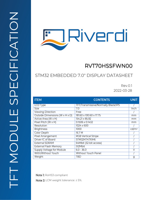
ITEM CONTENTS UNIT LCD Type TFT/Transmissive/Normally Black/IPS / Size 7.0 Inch Viewing Direction Free / Outside Dimensions (W x H x D) 181.60 x 100.60 x 17.75 mm Active Area (W x H) 154.21 x 85.92 mm Pixel Pitch (W x H) 0.1506 x 0.1432 mm Resolution 1024 x 600 / Brightness 1000 cd/m 2 Color Depth 16.7 M / Pixel Arrangement RGB Vertical Stripe / Driver IC of Board STM32H747XIH6 / External SDRAM 64Mbit (32-bit access) / External Flash Memory 512Mbit / Supply Voltage for Module 6.0 - 36.0 V With/Without Touch Without Touch Panel / Weight TBD g STM32 EMBEDDED 7.0" DISPLAY DATASHEET RVT70HSSFWN00 Rev.0.1 2022-03-28 F T M O D U L E S P E C I F I C A T I O N Note 1: RoHS3 compliant Note 2: LCM weight tolerance: ± 5%.REVISION RECORDREV NO. REV DATE CONTENTS REMARKS0.1 2022-03-28 Preliminary versionCONTENTSREVISION RECORD (2)CONTENTS (3)MODULE CLASSIFICATION INFORMATION (4)ASSEMBLY GUIDE (5)MODULE DRAWING (6)ABSOLUTE MAXIMUM RATINGS (7)ELECTRICAL CHARACTERISTICS (7)BACKLIGHT ELECTRICAL CHARACTERISTICS (7)ELECTRO-OPTICAL CHARACTERISTICS (8)BOARD INTERFACES AND CONNECTORS (10)USER INTERFACES (16)DISPLAY SEPCIFICATION (17)INSPECTION (17)RELIABILITY TEST (19)LEGAL INFORMATION (20)MODULE CLASSIFICATION INFORMATIONRV T 70 H S S F W N 00 1. 2. 3. 4. 5. 6. 7. 8. 9. 10.ASSEMBLY GUIDEMounting frameFor dimensions 3.5”, 4.3”, 5.0”, 7.0” and 10.1”, the product with mounting frame version is available. Thanks to the four catches attached to the side, frame provides strong assembly to the surface by mounting element (like the screw, see Figure 1). The frames are specially designed to fit Riverdi products perfectly. The diameter of the mounting hole is 3.5mm.Figure 1. Mounting frameABSOLUTE MAXIMUM RATINGSPARAMETER SYMBOL MIN MAX UNIT NOTESupply Voltage for Module VDD 0.0 48.0V Note 1Digital I/O signals Voltage - -0.5 3.3 Note 1,2Operating Temperature T OP-20 70 °CStorage Temperature T ST-30 80 °CStorage Humidity (@ 25 ± 5°C) H ST10 - % RHOperating Ambient Humidity (@ 25 ± 5°C) H OP10 - % RHNote 1. Exceeding maximum values may cause improper operation or permanent damageto the unit.Note 2. Most of the GPIOs have the 5.0 V tolerant input voltage, please refer to the datasheetof STM32H747XIH6 for more details.ELECTRICAL CHARACTERISTICSPARAMETER SYMBOL MIN TYP MAX UNIT Supply Voltage for Module VDD_IN 6.0 12.0 36.0 VPOWER‘ENABLE’ = ‘0’***************************I VDD_IN=6.0 V TBD TBD TBD uA ****************************I VDD_IN=12.0 V TBD TBD TBD uA ****************************I VDD_IN=24.0 V TBD TBD TBD uA ****************************I VDD_IN=36.0 V TBD TBD TBD uAPOWER‘ENABLE’ = ‘1’***************************I VDD_IN=6.0 V TBD TBD TBD mA ****************************I VDD_IN=12.0 V TBD TBD TBD mA ****************************I VDD_IN=24.0 V TBD TBD TBD mA ****************************I VDD_IN=36.0 V TBD TBD TBD mAInput Voltage “H” Level V IH 2.0 - 3.3 V Input Voltage “L” Level V IL 0 - 0.8 V Note. POWER ‘ENABLE’ refers to pin 4, ‘ENABLE’ of the power input connector(P2).By default, POWER ‘ENABLE’ = ‘1’,When POWER ‘ENABLE’ = ‘0’, the device is turned off.BACKLIGHT ELECTRICAL CHARACTERISTICSPARAMETER SYMBOL MIN TYP MAX UNIT NOTE Lifetime - - 50,000 - hours Note 1Note 1. Operating life means the period in which the LED brightness goes down to 50% ofthe initial brightness. Typical operating lifetime is the estimated parameter.ELECTRO-OPTICAL CHARACTERISTICSITEM SYMBOL CONDITION MIN TYP MAX UNIT RMK NOTEResponse Time Tr+Tfθ=0°∅=0° - 35 35 ms FIG 2. 4Contrast Ratio Cr 800 1000 - --- FIG 3. 1 Luminance δ- 75 - % FIG 3. 3 Figure 3.Contrast Ratio =Average Surface Luminance with all white pixels (P1,P2,P3,P4,P5) Average Surface Luminance with all black pixels (P1,P2,P3,P4,P5)Note 2.Surface luminance is the LCD surface from the surface with all pixels displaying white. For more information see Figure 3.Lv = Average Surface Luminance with all white pixels (P1, P2, P3, P4, P5)Note 3.The uniformity in surface luminance δWHITE is determined by measuring luminance at each test position 1 through 5, and then dividing the minimum luminance of 5 points luminance by maximum luminance of 5 points luminance. For more information see Figure 3.δ WHITE =Minimum Surface Luminance with all white pixels (P1,P2,P3,P4,P5) Maximum Surface Luminance with all white pixels (P1,P2,P3,P4,P5)Note 4. Response time is the time required for the display to transition from white to black (Rise Time, Tr) and from black to white (Decay Time, Tf). For additional information see Figure 2. The test equipment is Autronic-Melchers’s ConoScope series.Note 5. CIE (x, y) chromaticity, the x, y value is determined by measuring luminance at each test position 1 through 5, and then calculating the average value.Note 6. Viewing angle is the angle at which the contrast ratio is greater than 2. For TFT module the contrast ratio is greater than 10. The angles are determined for the horizontal or x axis and the vertical or y axis with respect to the z axis which is normal to LCD surface. For more information see Figure 4.Note 7. For viewing angle and response time testing, the testing data is based on Autronic-Melchers’s ConoScope series. Instruments for Contrast Ratio, Surface Luminance, Luminance Uniformity, CIE the test data is based on TOPCON’s BM-5 photo detector.Figure 2. The definition of response timeFigure 3. Measuring method for Contrast ratio, surface luminance, Luminance uniformity, CIE (x, y) chromaticityA: 5mmB: 5mmH, V: Active AreaLight spot size ∅=5mm, 500mm distancefrom the LCD surface to detector lens.Measurement instrument is TOPCON’Sluminance meter BM-5Figure 4. The definition of viewing angleBOARD INTERFACES AND CONNECTORSPower input connectorThe 1.25mm, 6-pin Molex connector labeled as “POWER’ (P2) is power input connector. There is an internal reverse polarity protection which ensures that the device is not damaged if the power supply polarity is reversed.NO. PIN DESCRIPTION NOTE1 VDD_IN Power supply input; 6.0-36.0VNote 12 VDD_IN Power supply input; 6.0-36.0V3 VDD_IN Power supply input; 6.0-36.0V4 ENABLE Enable/ Disable power supply. Note 25 GND Ground6 GND GroundNote 1: STM32 Embedded Display allows to directly connect one additional display to the system. There is RiBUS connector on the board where you can connect any of intelligent display from Riverdi based on EVE4 (BT817Q). However, please note that it may change power supply requirement as below:The power supply voltage must range between 7.0V- 14.0 V (TYP. 9.0 V), if Riverdi EVE4 10.1” series display is connected through RiBUS. At the same time, jumper P5 shall be configured according to subchapter 10.8, note 1.The power supply voltage ranges between 6.0 V- 36.0V if any of Riverdi EVE4 3.5”,4.3”,5.0” and 7.0” series display is connected through RiBUS. At the same time, jumper P12 shall be configured according to subchapter 10.8, note 1.Note 2: By default, pin “ENABLE” is pulled up to VDD and enabled. To disable, ground the pin to turn off the device completely.USB interfaceThe 1.25mm, 5-pin Molex connector labeled as “USB’ (P10) is USB interface.NO. PIN DESCRIPTION NOTE1 VCC_USB Power supply2 D- USB data-3 D+ USB data+4 ID USB OTG ID; Host /Device detect Note 15 GND GroundNote 1. Configuration of the USB Host/Device mode:Host Mode: Pin 4 (ID) should be connected to GND.In this mode, it can provide +5V output voltage to the connected USB device and Max output current 500 mA.Device Mode: Pin 4 (ID) should be not connected (floating).RS485 interfaceThe 1.25mm, 4-pin Molex connector labeled as “RS485’ (P3) is RS485 interface.NO. PIN DESCRIPTION NOTE1 VDD_IN Power supply input; 6.0-36.0V2 A Non-inverting receiver input and non-inverting driver output3 B Inverting receiver input and inverting driver output4 GND GroundRS232 interfaceThe 1.25mm, 5-pin Molex connector labeled as “RS232’ (P1) is RS232 interface.NO. PIN DESCRIPTION NOTE1 RTS Request to send2 CTS Clear to send3 TXD Transmit Data4 RXD Receive Data5 GND Ground2 x CAN FD interfacesThe main board supports 2 channels of the CANFD (Control Area Network Flexible Data-Rate) communication bus, based on the high-speed (2.5-8.0Mbps) CAN transceiver.2 pcs of 1.25mm, 4-pin Molex connectors labeled as “CAN1’ (P11) and “CAN2” (P15) are respectively interfaces of CAN FD1 and CAN FD2.NO. PIN DESCRIPTION NOTE1 GND Ground2 CAN_L CAN Low-Level Voltage3 CAN_H CAN High-Level Voltage4 VDD_IN Power supply input; 6.0 – 36.0 VHaptic feedback connectorThe 1.25mm, 2-pin Molex connector labeled as “HAPTIC’ (P7) is haptic feedback connector. Haptic feedback P7 is used to connect with the haptic motor directly.NO. PIN DESCRIPTION NOTE1 OUT- Negative haptic driver differential outputNote 12 OUT+ Positive haptic driver differential outputNote 1: The haptic driver DRV2605L is controlled directly by I2C protocolSWD (Serial Wire Debug) connectorThe 1.25mm, 6-pin Molex connector labeled as ‘SWD’ (P6) is SWD interface, which is used for programing the MCU on board.NO. PIN DESCRIPTION NOTE1 VCC_+3.3V Power input2 SW_CLK Serial wire clock3 GND Ground4 SW_DIO Serial wire debug data input/output5 RST Reset; Active low6 SWO Serial wire trace outputRiBUSAny size of the Riverdi EVE4 series display can be connected through RiBUS to act as a slave module to the mainboard.NO. PIN DESCRIPTION NOTE1 VCC_+3.3V Supply voltage for module; TYP3.3Vbetween 7.0 - 14.0V (TYP. 9V).For Riverdi EVE4 series display ranging from sizes of 3.5” to 7.0”, the backlight voltage (BLVDD) shall be 5.0V.Backlight jumper selectors, P5 and P12, labeled as “BLVDD SEL EXT”and “BLVDD SEL INT are used to configure the backlight voltage range.Warning! Jumper configuration shall be done when module is not powered.DO NOT change ANY jumpers while the module has power. Improper operation might cause permanent damage to the unit.Please pay special attention to not misplace the jumpers. Incorrect jumpers setting may lead to damage to the module as well.The P5, P12 jumpers setting are shown below.Table 1. Internal backlight selector P12 setting: 5.0V (default) backlight voltageSETTING P5, PIN 1 &2P5, PIN 3 &4P12, PIN 1 &2P12, PIN 3 &45.0V (Default) Open Open Short ShortTable 2. External backlight selector P5 setting: 7.0V-14.0V backlight voltageSETTING P5, PIN 1 &2P5, PIN 3 &4P12, PIN 1 &2P12, PIN 3 &47.0V - 14.0 V Short Short Open OpenExpansion connectorThe main board has one 1.27mm, 40-pin expansion pin header which is labeled as “EXPANSION CONNECTOR’ (P8).It provides direct access to below GPIOs of MCU STM32H747XIH6,which make it possible to easily extend a daughterboard for a specific application.• 2 x I2C• 1 x UART• 1 x USART• 1 x SPI• 1 x USB•7 x PWMs• 2 x DACs (Digital-to-analog)• 2 x ADCs (Analog-to-digital)Each of the GPIO pins can be configured by software as output (push-pull or open-drain, with or without pull-up or pull-down), as input (floating, with or without pull-up or pull-down) or as peripheral alternate function. Most of the GPIO pins are shared with digital or analog alternate functions. Please refer to the datasheet of MCU STM32H747XIH6 for more details.I/O/P PIN NAME NO. NO. PIN NAME I/O/PP VCC_+5V 1 2 VCC_+3.3V PP VCC_+5V 3 4 VCC_+3.3V PI/O PA5 5 6 GND PP GND 7 8 PA4 I/OI/O PE4 9 10 PD11 I/OI/O PK1 11 12 PB10 I/OI/O PD12 13 14 PC7 I/OI/O PD13 15 16 PA3 I/OP GND 17 18 GND PI/O PC2 19 20 PA0_C I/OI/O PC3 21 22 PA1_C I/OI/O PA12 23 24 PC2_C I/OI/O PA9 25 26 PC3_C I/OI/O PA10 27 28 GND PI/O PJ8 29 30 PC13 I/OI/O P18 31 32 PA8 I/OI/O PJ10 33 34 PB11 I/OI/O PB0 35 36 PH4 I/OI/O PC6 37 38 PB12 I/OI/O PB14 39 40 PB15 I/ONote 1. ***************************from pin 1 and pin3 is maximum 1A.********************************************************.Note 2.The ‘USR LED’ is connected to pin 33, PJ10, of the expansion connector.By default, the resistor R60, (0402, 1k ohms) is soldered. Please remove R60 to useGPIO channel PJ10.Note 3. Push button BTN2(S2) is connected to pin 35, PB0, of the expansion connector. Please remove R58 to use GPIO channel PB0.Push button BTN1(S1) is connected to pin 37, PC6, of the expansion connector.Please remove R57 to use GPIO channel PC6.Micro SD slotThe mainboard is equipped with Micro-SD slot, which supports all types of Micro SD cards.2 x 20-pin, 1.27 mm pin sockets for POE Add-on BoardThe 2 x 20-pin, 1.27 mm, pin sockets, labeled as U9a and U9b, are used to connect the Riverdi POE Add-on Board.The Riverdi POE Add-on Board features 10/100M Ethernet Port with Power-Over-Ethernet enabled. It allows you to power the module through the Ethernet port.Note. The Riverdi POE Add-on Board is offered as an accessory.USER INTERFACES3 x push buttonsPush button labeled as “RST” is used to “RESET” the module.Another 2 push buttons labeled as BTN1, BTN2 are for user’s development.•BTN1(S1) is connected to pin 37, PC6, of the expansion connector.•BTN2(S2) is connected to pin 35, PB0, of the expansion connector.By default, pushbuttons BTN1(S1), BTN2(S2) are enabled. To use GPIO channel PC6 and PB0, R57 and R58 should be removed.3 x LEDs1 x LED, labeled as ‘PWR LED’, emits green light when the modules is powered.1 x LED, labeled as ‘USB OVR’, emits red light when VCC_USB pin is shorted.1 x LED, labeled as ‘USR LED’, is for user’s development.•The ‘USR LED’ is connected to pin 33, PJ10, of the expansion connector.By default, the resistor R60, (0402, 1k ohms) is soldered. Please remove R60 to use GPIO channel PJ10.D ISPLAY SEPCIFICATIONTFT resolutionThe supported resolution of the display in this module is 1024*600.Full TFT specificationFor detailed information on the display, please refer to datasheet of displayRVT70HSMFWN00.I NSPECTIONStandard acceptance/rejection criteria for TFT moduleInspection conditionAmbient conditions:•Temperature: 25 ± 2°C•Humidity: (60 ± 10) %RH•Illumination: Single fluorescent lamp non-directive (300 to 700 lux) Viewing distance: 35 ± 5cm between inspector bare eye and LCD.Viewing Angle: U/D: 45°/45°, L/R: 45°/45°Inspection standardITEM CRITERIONBlack spots,white spots,light leakage,Foreign Particle(round Type)D=(x+y)/2Spot’s density: 10 mmSize = 7”Average Diameter Qualified QtyD ≤ 0.2 mm Ignored0.2 mm < D ≤ 0.3 mm N≤30.5mm < D Not allowed 0.5mm < DLCD black spots, white spots, light leakage (line Type)Size = 7”Length Width Qualified Qty - W ≤ 0.05IgnoredL ≤ 5.00.05 < W ≤ 0.1 35.0 < L 0.1 < W Not allowedBright/Dark DotsSize = 7”Item Qualified Qty Bright dots N≤2Dark dots N≤3 Total bright and dark dots N≤4Clear spotsSize = 7”Average Diameter Qualified QtyD < 0.2 mm Ignored0.2 mm < D < 0.3 mm 40.3 mm < D < 0.5 mm 20.5 mm < D 0Polarizer bubblesSize = 7”Average Diameter Qualified QtyD ≤ 0.2 mm Ignored0.2 mm < D ≤ 0.5 mm 40.5 mm < D 0Touch panel spotSize ≥ 5"Average Diameter Qualified QtyD < 0.25 mm Ignored0.25 mm < D < 0.5 mm 40.5 mm < D 0Touch panel White line ScratchSize ≥ 5’’Length Width Qualified Qty - W < 0.03 IgnoredL < 5.0 0.03 < W < 0.05 2- 0.05 < W 0RELIABILITY TESTNO.TEST ITEMTEST CONDITIONNOTE1 High Temperature Storage 80°C/120 hoursNote 12 Low Temperature Storage -30°C/120 hours3 High Temperature Operating 70 °C /120 hours Note 2. Before cosmetic and function test, the product must have enough recovery time, at least 2 hours at room temperature.L EGAL INFORMATIONRiverdi grants the guarantee for the proper operation of the goods for a period of 12 months from the date of possession of the goods. If in a consequence of this guaranteed execution the customer has received the defects-free item as replacement for the defective item, the effectiveness period of this guarantee shall start anew from the moment the customer receives the defects-free item.Information about device is the property of Riverdi and may be the subject of patents pending or granted. It is not allowed to copy or disclosed this document without prior written permission.Riverdi endeavors to ensure that all contained information in this document is correct but does not accept liability for any error or omission. Riverdi products are in developing process and published information may be not up to date. Riverdi reserves the right to update and makes changes to Specifications or written material without prior notice at any time. It is important to check the current position with Riverdi.Images and graphics used in this document are only for illustrative the purpose. All images and graphics are possible to be displayed on the range products of Riverdi, however the quality may vary. Riverdi is no liable to the buyer or to any third party for any indirect, incidental, special, consequential, punitive, or exemplary damages (including without limitation lost profits, lost savings, or loss of business opportunity) relating to any product, service provided or to be provided by Riverdi, or the use or inability to use the same, even if Riverdi has been advised of the possibility of such damages.Riverdi products are not fault tolerant nor designed, manufactured or intended for use or resale as on line control equipment in hazardous environments requiring fail–safe performance, such as in the operation of nuclear facilities, aircraft navigation or communication systems, air traffic control, direct life support machines or weapons systems in which the failure of the product could lead directly to death, personal injury or severe physical or environmental damage (‘High-Risk Activities’). Riverdi and i ts suppliers specifically disclaim any expressed or implied warranty of fitness for High-Risk Activities. Using Riverdi products and devices in 'High-Risk Activities' and in any other application is entirely at the buyer’s risk, and the buyer agrees to def end, indemnify, and hold harmless Riverdi from all damages, claims or expenses resulting from such use. No licenses are conveyed, implicitly or otherwise, under any Riverdi intellectual property rights.。
波特科技梅特曼35 XP数字多功能测试仪说明书

Meterman DatasheetMODEL: 35 XP DIGITAL MULTIMETER8-1/2" X 11" 2-3 pages (extended version for web)LOGO: Wavetek MetermanHEAD: The 35XP Digital MultimeterSUB: The compact, full-featured meter for facilities, HVAC technician, residential and commercial electriciansPHOTO: (35XP meter)INSET PHOTO: (35XP with Voltect)LOGO: Voltect™ Non-Contact Voltage DetectorINSET PHOTO: (35XP with temperature thermocouple/application photo)temperature. Thermocouple included.CAPTION: MeasuresINSET PHOTO: (35xp with Magne-Grip holster)CAPTION: Magne-Grip holster frees both hands for work.The Wavetek Meterman 35 XP digital multimeter provides superior features and accuracy in a smaller form factor. The 35 XP has unique features such as VolTect™non-contact voltage(NCV) detection, temperature high energy safety ratings and our exclusive Magne-Grip™ holster that frees both hands.The 35XP is the right choice for HVAC, plant maintenance technicians and residential electricians.SUB:Features that help you take more measurements, faster, safer and easier.• VolTect™ non-contact voltage detection lets you instantly detect dangerous AC voltage• Magne-Grip holster with magnetic hanging strap with frees both hands for work• 4000 count resolution provides more precise measurements• Temperature measurement capability to 1000 °C/1832 °F is good for HVAC and industrial applications.(Type K thermocouple included)• 750 V AC/ 1000 V DC - highest voltage rating in this class of meter• Capacitance for testing motor run/test capacitance• Frequency lets you test and verify control systems• Resistance and continuity for troubleshooting bad connections• Data hold lets you freeze measurements on the display which lets you use the test probes without looking at the display• Triple safety rating protects against line surges and overvoltage conditions• CAT I 1000 V• CAT II 600 V• CAT III 300 VSUB: Product includes:• Model 35XP compact digital multimeter• Test leads• Type K thermocouple• Temperature adapter• Manual• Battery (installed)SPECIFICATIONS• Display: 3¾ digit liquid crystal display (LCD) with a maximum reading of 3999.• Polarity: Automatic, positive implied, negative polarity indication.• Overrange: (OL) or (-OL) is displayed.• Zero: Automatic.• Low battery indication: The "Ν" is displayed when the battery voltage drops below the operating level.3:10 PM, 05/24/04, Page• Auto power off: Approx. 10 minutes.• Measurement rate: 2 times per second, nominal.• Operating environment: 0°C to 50°C at <70% R.H.• Storage temperature: -20°C to 60°C, 0 to 80% R.H. with battery removed from meter.• Accuracy: Stated accuracy at 23°C ± 5°C, <75% relative humidity.• Temperature Coefficient: 0.1 × (specified accuracy) per °C. (0°C to 18°C, 28°C to 50°C).• Altitude: 6561.7 Feet (2000M).• Power: Single standard 9-volt battery, NEDA 1604, JIS 006P, IEC 6F22.• Battery life: 150 hours typical with carbon-zinc. 300 hours typical with alkaline.• Dimensions: 155mm (H) ×72mm (W) ×32mm (D).• Weight: Approx. 400g including battery.• Accessories: One pair test leads TL245, Fuse 2A/1000V(installed), 9V battery (installed) and Operating Instructions holster, magnet strap, temperature adapter, K-type thermocouple.• Safety: Designed to meet IEC 1010-1, Rev-2 CAT I 1000V, CAT II 600V, CAT III 300V, class 2 and pollution deg. 2 indoor use comply with CE, CSA 22.2-1010-1.DC VOLTSRanges: 400mV, 4V, 40V, 400V, 1000VResolution: 100µVAccuracy: ±(0.5% rdg + 1 dgt)Input impedance:400mV: >100MΩ; 4V: 10MΩ; 40V ~ 1000V: 9.1MΩOverload protection: 1000VDC or 750VAC rmsAC VOLTS (45Hz - 500Hz)Ranges: 400mV, 4V, 40V, 400V, 750VResolution: 100µVAccuracy: ± (1.5% rdg + 5 dgts) 45Hz ~ 100Hz on 400mV range± (1.5% rdg + 5 dgts) on 4V to 750V rangesInput impedance: 400mV: >100MΩ; 4V: 10MΩ; 40V ~ 1000V: 9.1MΩOverload protection: 1000 VDC or 750VAC rmsDC CURRENTRanges: 400µA, 4000µA, 40mA, 400mA, 2AResolution: 0.1µAAccuracy: ± (1.0% rdg + 2 dgt) on 400µA to 400mA ranges± (2.0% rdg + 3 dgts) on 2A rangeInput protection: 2A/1000V fast blow ceramic fuse 6.3×32mm on A inputBurden voltage: 500mV max. (2V max. on 4mA, 400mA ranges)AC CURRENT (45Hz - 500Hz)Ranges: 400µA, 4000µA, 40mA, 400mA, 2AResolution: 0.1µAAccuracy: ± (1.5% rdg + 5 dgts) on 400µA to 400mA ranges± (2.5% rdg + 5dgts) on 2A rangeInput protection: 2A/1000V fast blow ceramic fuse 6.3×32mm on A inputBurden voltage: 500mV max. (2V max. on 4mA, 400mA ranges)RESISTANCERanges: 400Ω, 4kΩ, 40kΩ, 400kΩ, 4MΩ, 40MΩResolution: 100mΩAccuracy: ± (1.0% rdg + 4 dgts) on 400Ω to 4MΩ ranges± (2.0% rdg + 5 dgts) on 40MΩ rangeOpen circuit volts: -0.45V dc typical, (-1.2Vdc on 400Ω range)Overload protection: 1000VDC or 750VAC rmsCAPACITANCERanges: 4nF, 40nF, 400nF, 4µF, 40uF, 400uF, 4mFResolution: 1pFAccuracy: ± (5.0% rdg + 30 dgts) on 4nF to 4µF ranges3:10 PM, 05/24/04, Page± (5.0% rdg + 5 dgts) on 40µF to 400µF ranges± (5.0% rdg + 15 dgts) on 4mF rangesTest voltage: < 1VTest Frequency: 1.3Hz on 4nF to 40µF ranges, 0.7Hz on 400µF, 4mF rangesInput protection: 2A/1000V fast blow ceramic fuse 6.3×32mm on A inputTEMPERATURERanges: -20°C ~ 1000°C, -4°F ~ 1832°FResolution: 0.1°C, 0.1°FAccuracy: ± (2.0% rdg + 4°C) -20°C ~ 10°C± (1.0% rdg + 3°C) 10°C ~ 200°C± (3.0% rdg + 2°C) 200°C ~ 1000°C± (2.0% rdg + 8°F) -4°F ~ 50°F± (1.0% rdg + 6°F) 50°F ~ 400°F± (3.0% rdg + 4°F) 400°F ~1832°FOverload protection: 1000VDC or 750VAC rmsFREQUENCYRanges: 4k, 40k, 400k, 4M, 40MHzResolution: 1HzAccuracy: ± (0.1% rdg + 3 dgts)Sensitivity: 10Hz ~ 4MHz: >1.5V rms; 4MHz ~ 40MHz: >2V rms, <5V rmsMinimum pulse width: > 25nsDuty cycle limits: > 30% and < 70%Overload protection: 1000VDC or 750VAC rmsCONTINUITYAudible indication: Less than 25ΩResponse time: 100msOverload protection:1000VDC or 750VAC rmsDIODE TESTTest current: 1.2mA (approximate)Accuracy: ± (1.5% rdg + 3 dgts)Resolution: 1mVOpen circuit volts: 3.0 dc typicalOverload protection: 1000VDC or 750VAC rmsNON-CONTACT VOLTAGE INDICATORSense voltage 70V to 600VAC beeper chirps and big bright red LED comes on, works on all ranges. AUXILIARY FEATURESDATA HOLD: Freeze the latest reading on the display.RANGE: Execute manual range mode.AUTO Power off: After auto power off, press any button to restart the meter, and the last reading of measurement will be maintained in the display.A JACK: Input warning detects wrong connectionStandard address block and literature code3:10 PM, 05/24/04, Page。
[工作范文]35寸真彩色TFT串...
![[工作范文]35寸真彩色TFT串...](https://img.taocdn.com/s3/m/4fce6ac748649b6648d7c1c708a1284ac8500532.png)
版权声明北京铭正同创科技有限公司保留对此文件修改的权利且不另行通知。
北京铭正同创科技有限公司所提供的信息相信为正确且可靠的信息, 但并不保证本文件中绝无错误。
请于向北京铭正同创科技有限公司提出订单前, 自行确定所使用的相关技术文件及产品规格为最新版本。
若因贵公司使用本公司的文件或产品, 而涉及第三人之专利或著作权等知识产权的应用时, 则应由贵公司负责取得同意及授权,关于所述同意及授权, 非属本公司应为保证的责任。
目 录1 模块简介 (1)1.1 特点 (1)1.2 主要功能与基本参数 (1)1.3 结构及引脚示意 (2)1.4 模块内置资源存储器与MrsTool工具关系简述 (4)1.4.1 MzTH35V10_TP模块与MrsToolV11连接 (6)1.4.2 MzTH35V10_TP模块资源存储器出厂设置 (8)1.4.3 MzTH35V10_TP模块的新建资源选项 (9)2 液晶显示器介绍 (10)2.1 显示屏坐标点映射关系 (10)3 模组控制方法 (11)3.1 操作时序 (11)3.2 模块控制指令数据包构成 (12)3.3 模块返回数据包构成 (12)3.4 控制指令 (12)3.4.1 基本显示控制指令 (12)3.4.2 滚屏控制指令 (16)3.4.3 触摸功能控制指令 (17)3.5 模块基本显示控制指令详述 (18)3.5.1 模块背光控制 (18)3.5.2 绘图前景色设置 (18)3.5.3 ASCII字符型号设置 (19)3.5.4 汉字字库设置 (20)3.5.5 字符覆盖模式设置 (20)3.5.6 位图显示指令 (20)3.5.7 直接数字显示指令 (22)3.5.8 低功耗模式设置 (23)3.5.9 以忽略色模式显示图片 (23)3.5.10 区域取反显示 (24)3.6 滚屏控制指令详述 (26)3.6.1 设置滚屏区域指令 (26)3.6.2 手动滚动滚屏区域指令 (26)3.6.3 自动滚屏指令 (26)3.6.4 结束滚屏指令 (27)3.7 触摸功能控制指令详述 (27)3.7.1 触摸屏功能 (27)3.7.2 触摸区域设置 (29)3.7.3 位图触摸按键 (31)3.7.4 触摸区域和位图触摸按键使用实例 (33)4 设计参考 (36)4.1 模块与单片机的连接示意 (36)4.2 与模块通讯的接口函数 (36)4.3 操作示例 (38)5 模块各指令执行时间 (40)6 利用USB口快速测试模块 (43)7 技术支持 (46)7.1 联系方式 (47)1模块简介1.1特点MzTH35V10_TP是MzTH系列彩色多功能显示模块中的一款功能上较特殊的3.5英寸(对角线)彩色TFT显示模块,MzTH35V10_TP自带四种字号的ASCII码西文字库,并且自带基本绘图GUI功能,包括画点、画直线、矩形、圆形等;而如其它型号的MzTH系列模块一样,MzTH35V10_TP标准模块内部有4M bytes大小的资源存储器,支持GBK2312的二级(包含一级和二级)汉字库、BMP位图、ASCII码西文字库的资源。
Riverdi 3.5英寸 TFT 显示屏参考手册说明书

ITEMCONTENTSUNITLCD Type TFT/Transmissive/Normally white / Size3.5Inch Viewing Direction12:00 (without image inversion) O’ Clock Gray Scale Inversion Direction 6:00O’ Clock Number of Dots 320 x (RGB) × 240 / Driver ICBT81x / Interface TypeSPI/QSPI/ Module Memory Size 1 MB (BT81x) + 64 Mb (external flash) / Color Depth16.7M/ Pixel Arrangement RGB Vertical Stripe/ Surface Treatment Anti-glare / Clear (for CTP) / Input Voltage3.3V3.5” EVE3 SERIES LCD TFTRiTFT-35 seriesRev.1.0 2018-10-22L C D T F T M o d u l e S p e c i f i c a t i o nNote 1: RoHS, REACH SVHC compliant Note 2: LCM weight tolerance: ± 5%.CONTENTS (2)1 MODULE CLASSIFICATION INFORMATION (3)2 ASSEMBLY GUIDE - INTEGRATION (3)2.1 Mounting frame (4)3 MODULE DRAWING (4)4 ABSOLUTE MAXIMUM RATINGS (5)5 ELECTRICAL CHARACTERISTICS (5)6 BACKLIGHT CHARACTERISTICS (5)7 ELECTRO-OPTICAL CHARACTERISTICS (5)8 INTERFACE DESCRIPTION (7)9 BT8x CONTROLLER SPECIFICATIONS (8)9.1 Serial host interface (8)9.2 Block Diagram (8)9.3 Host interface SPI mode 0 (9)9.4 Backlight driver block diagram (9)10 LCD TIMING CHARACTERISTICS (9)10.1 Clock and data input time diagram (9)10.2 Parallel RGB timing table (11)11 TOUCH SCREEN PANEL SPECIFICATIONS (11)11.1 Electrical characteristics (11)11.1.1 For capacitive touch panel (11)11.1.2 For resistive touch panel (12)11.2 Mechanical characteristics (12)11.2.1 For capacitive touch panel (12)11.2.2 For resistive touch panel (13)12 INSPECTION (13)12.1 Inspection condition (13)12.2 Inspection standard (14)13 RELIABILITY TEST (17)14 LEGAL INFORMATION (18)1. BRAND RV – Riverdi2. PRODUCT TYPE T – TFT StandardF – TFT Custom3. DISPLAY SIZE 35– 3.5”4. MODEL SERIAL NO. A (A-Z)5. RESOLUTION H– 320x240 px6. INTERFACE B – TFT + Controller BT81x7. FRAME N – No FrameF – Mounting Frame8. BACKLIGHT TYPE W – LED White9. TOUCH PANEL N – No Touch PanelR – Resistive Touch Panel C – Capacitive Touch Panel10. VERSION 00(00-99)RiTFT-35-RES RVT35AHBNWR00 BT816, resistive touch panelRiTFT-35-CAP RVT35AHBNWC00 BT815, capacitive touch panelRiTFT-35-FR RVT35AHBFWN00 BT816, no touch panel, mounting frame RiTFT-35-RES-FR RVT35AHBFWR00 BT816, resistive touch panel, mounting frame RiTFT-35-CAP-FR RVT35AHBFWC00 BT815, capacitive touch panel, mounting frame2.1Mounting frameFor dimension s 3.5”, 4.3”, 5.0” and 7.0” the product with mounting frame version is available. Thanks to the four catches attached to the side, frame provides strong assembly to the surface by mounting element (like the screw, see Figure 3). The frames are specially designed to fit Riverdi products perfectly. The diameter of the mounting hole is 3.5mm.Figure 1. Mounting frameRiTFT-35 series3MODULE DRAWING `` RiTFT-35© 2018 Riverdi Page 4 of 24 RiTFT-35 seriesRiTFT-35-FR© 2018 Riverdi Page 5 of 24 RiTFT-35 seriesRiTFT-35-CAP© 2018 Riverdi Page 6 of 24 RiTFT-35-CAP-FR© 2018 Riverdi Page 7 of 24 RiTFT-35-RES© 2018 Riverdi Page 8 of 24 RiTFT-35-RES-FR© 2018 Riverdi Page 9 of 24 4ABSOLUTE MAXIMUM RATINGSPARAMETER SYMBOL MIN MAX UNITSupply Voltage for Logic VDD 0 4.0 V Supply Voltage for LED Inverter BLVDD 0 7.0 VInput Voltage for Logic VIN 0 4.0 VLED forward current (each LED) IF - 25 mA Operating Temperature T OP-20 70 °C PARAMETER SYMBOL MIN TYP MAX UNIT NOTES Supply Voltage For Module VDD 3.0 3.3 3.6 VInput Voltage for LED Inverter BLVDD 2.8 5.0 5.5 VLED Backlight Current IDD backlight- 150 187 mA BLVDD=3.3V LED Backlight Current IDD backlight- 93 117 mA BLVDD=5V Input Voltage ' H ' level V IH0.7VDD - VDD VInput Voltage ' L ' level V IL0 - 0.2VDD VInput Current I In TBD mAInput Current for module with CTP I InC TBD mAITEM SYMBOL MIN TYP MAX UNIT Voltage for LED backlight V l- 19.2 20.4 V Current for LED backlight I l- 20 25 mA LED Life Time - 30000 50000 - HrsLNote 1. Contrast Ratio(CR) is defined mathematically as below, for more information see Figure .Contrast Ratio =Average Surface Luminance with all white pixels (P1,P2,P3,P4,P5) Average Surface Luminance with all black pixels (P1,P2,P3,P4,P5)Note 2. Surface luminance is the LCD surface from the surface with all pixels displaying white. For more information, see Figure .Lv = Average Surface Luminance with all white pixels (P1, P2, P3, P4, P5)Note 3.The uniformity in surface luminance δ WHITE is determined by measuring luminance at each test position 1 through 5, and then dividing the maximum luminance of 5 points luminance by minimum luminance of 5 points luminance. For more information, see Figure .δ WHITE =Minimum Surface Luminance with all white pixels (P1,P2,P3,P4,P5) Maximum Surface Luminance with all white pixels (P1,P2,P3,P4,P5)Note 4. Response time is the time required for the display to transition from white to black (Rise Time, Tr) and from black to white (Decay Time, Tf). For additional information see FIG 1. The test equipment is Autronic-Melchers’s ConoScope series.Note 5.CIE (x, y) chromaticity, the x, y value is determined by measuring luminance at each test position 1 through 5, and then make average value.Note 6. Viewing angle is the angle at which the contrast ratio is greater than 2. For TFT module the contrast ratio is greater than 10. The angles are determined for the horizontal or x axis and the vertical or y axis with respect to the z axis which is normal to the LCD surface. For more information see Figure .Note 7. For viewing angle and response time testing, the testing data is based on Autronic-Melchers’s ConoScope series. Instruments for Contrast Ratio, Surface Luminance, Luminance Uniformity, CIE the test data is based on TOPCON’s BM-5 photo detector.Note 8. For TFT module, Gray scale reverse occurs in the direction of panel viewing angle.Figure 2. The definition of response timeFigure 3. Measuring method for Contrast ratio, surface luminance, Luminance uniformity, CIE (x, y) chromaticityFigure 4.The definition of viewing angle8INTERFACE DESCRIPTION9BT8x CONTROLLER SPECIFICATIONSBT8x or EVE3 (Embedded Video Engine 3) simplifies the system architecture for advanced human machine interfaces (HMIs) by providing functionality for display, audio, and touch as well as an object oriented architecture approach that extends from display creation to the rendering of the graphics.9.1Serial host interfaceFigure 5.SPI interface connection Figure 6. QSPI interface connectionSPI Interface– the SPI slave interface operates up to 30MHz.Only SPI mode 0 is supported. The SPI interface is selected by default (MODE pin is internally pulled low by 47k resistor).9.2Block DiagramFigure 7.. BT8x Block diagram9.3Host interface SPI mode 0Figure 8. SPI timing diagramFor more information about BT8x controller please go to official BT8x website.https:///Products/ICs/BT81X.html9.4Backlight driver block diagramBacklight enable signal is internally connected to BT8x Backlight control pin. This pin is controlled by two BT8x’s registers. One of them specifies the PWM output frequency, second one specifies the duty cycle. Refer to BT8x datasheet for more information.Figure 9. Backlight driver block diagram10LCD TIMING CHARACTERISTICS10.1Clock and data input time diagramFigure 10. DE mode timing diagramBT8xFigure 11. SYNC mode timing diagramFigure 12. Timing diagram10.2Parallel RGB timing tableTiming parameter (VDD=3.3V, GND=0V, Ta=25˚C)PARAMETER SYMBOL MIN TYP MAX UNIT CONDITION CLK Clock Time T clk 1/Max(F CLK) - 1/Min(F CLK) ns -11TOUCH SCREEN PANEL SPECIFICATIONS11.1Electrical characteristicsNote: Avoid operating with hard or sharp material such as a ball point pen or a mechanical pencil except a polyacetal pen (tip R0.8mm or less) or a fingerITEM VALUE UNIT REMARKMin. Typ. Max.Linearity - - 1.5 % Analog X and Y directions Terminal Resistance 200 - 900 ΩX100 - 600 ΩY11.2Mechanical characteristicsNote 1: Force test condition, Input DC 5V on X direction, Drop off Polyacetal Stylus (R0.8), until output voltage stabilize, then get the R8.0mm Silicon rubber and do finger Activation force test. Next step, 9 points.Note 2: Measurement surface area conditions, Scratch 100,000 times straight line on the film with a stylus change every 20,000 times with Force: 250gf, Speed: 60mm/sec by R0.8 polaceteal stylus.Note 3: Pitting test, Pit 1, 000, 000 times on the film with R0.8 silicon rubber with Force: 250gf and Speed: 2 times/sec.Note 1: Force test condition, Input DC 5V on X direction, drop off Polyacetal Stylus (R0.8), until output voltage stabilize, then get the R8.0mm Silicon rubber and do finger Activation force test. Next step, 9 points.ITEM VALUE UNIT REMARKMin. Typ. Max.12INSPECTIONStandard acceptance/rejection criteria for TFT module.12.1Inspection conditionAmbient conditions:•Temperature: 25±°C•Humidity: (60±10) %RH•Illumination: Single fluorescent lamp non-directive (300 to 700 lux)Viewing distance:35±5cm between inspector bare eye and LCD.Viewing Angle:U/D: 45°/45°, L/R 45°/45°12.2Inspection standard Item Criterion Black spots, whitespots, light leakage,Foreign Particle(round Type)D=(x+y)2*Spots density: 10 mmSize < 5”Average Diameter Qualified QtyD < 0.2 mm Ignored0.2 mm < D < 0.3 mm 30.3 mm < D < 0.5 mm 20.5 mm < D 0Size >= 5”Average Diameter Qualified Qty D<0.2 mm Ignored0.2 mm < D < 0.3 mm 40.3 mm < D < 0.5 mm 20.5 mm < D 0Clear spotsSize >= 5”Average Diameter Qualified Qty D<0.2 mmIgnored 0.2 mm < D < 0.3 mm 4 0.3 mm < D < 0.5 mm 2 0.5 mm < D*Spots density: 10 mm Size < 5”Average Diameter Qualified Qty D < 0.2 mmIgnored 0.2 mm < D < 0.3 mm 3 0.3 mm < D < 0.5 mm 2 0.5 mm < D 0Polarizer bubblesSize < 5”Average Diameter Qualified Qty D < 0.2 mmIgnored 0.2 mm < D < 0.5 mm 3 0.5 mm < D < 1 mm 2 1 mm < D 0 Total Q’ty 3Size >= 5”Average Diameter Qualified Qty D<0.25 mmIgnored 0.25 mm < D < 0.5 mm 3 0.5 mm < D 0Electrical Dot DefectSize < 5”itemQualified Qty Black do defect 4 Bright dot defect 2 Total Dot 5Size >= 5”itemQualified Qty Black do defect 5 Bright dot defect 2 Total Dot 5Touch panel spotSize < 5”Average Diameter Qualified QtyD < 0.2 mm Ignored0.2 mm < D < 0.4 mm 50.4 mm < D < 0.5 mm 213RELIABILITY TESTNO. TEST ITEM TEST CONDITION REMARKS1 High Temperature Storage 80±2°C/240hours Note 22 Low Temperature Storage -30±2°C/240hours Note 1,2Note 1: Without water condensation.Note 2:The function test shall be conducted after 2 hours storage at the room temperature and humidity after removed from the test chamber.14LEGAL INFORMATIONRiverdi makes no warranty, either expressed or implied with respect to any product, and specifically disclaims all other warranties, including, without limitation, warranties for merchantability, non-infringement and fitness for any particular purpose. Information about device are the property of Riverdi and may be the subject of patents pending or granted. It is not allowed to copy or disclosed this document without prior written permission.Riverdi endeavors to ensure that the all contained information in this document are correct but does not accept liability for any error or omission. Riverdi products are in developing process and published information may be not up to date. Riverdi reserves the right to update and makes changes to Specifications or written material without prior notice at any time. It is important to check the current position with Riverdi.Images and graphics used in this document are only for illustrative the purpose. All images and graphics are possible to be displayed on the range products of Riverdi, however the quality may vary. Riverdi is no liable to the buyer or to any third part for any indirect, incidental, special, consequential, punitive or exemplary damages (including without limitation lost profits, lost savings, or loss of business opportunity) relating to any product, service provided or to be provided by Riverdi, or the use or inability to use the same, even if Riverdi has been advised of the possibility of such damages.Riverdi products are not fault tolerant nor designed, manufactured or intended for use or resale as on line control equipment in hazardous environments requiring fail – safe performance, such as in the operation of nuclear facilities, aircraft navigation or communication systems, air traffic control, direct life support machines or weapons systems in which the failure of the product could lead directly to death, personal injury or severe physical or environmental damage (‘High Risk Activities’). Riverdi and its suppliers specifically disclaim any expressed or implied warranty of fitness for High Risk Activities. Using Riverdi products and devices in 'High Risk Activities' and in any other application is entirely at the buyer’s risk, and the buyer agrees to defend, indemnify and hold harmless Riverdi from any and all damages, claims or expenses resulting from such use. No licenses are conveyed, implicitly or otherwise, under any Riverdi intellectual property rights.。
3.5寸TFT液晶规格书
Contents TFT transmissive, Normally white 6 O’clock 54.66(W)X82.94(H)X2.3(T) 48.96(W) x 73.44(H) 320(H) x (R.G.B.) x480(W) HX8357B 262K LED NC 8080 system 8/16 bit parallel T.B.D.
TEL: 86-0755-23000930 FAX : 86-0755-23000936
Doc No: Rev.:
XC-T0353701 0 2012.03.26
6 of 23
深圳信创光电技术有限公司
SHEN ZHEN SHI SINGSTART OPTOELECTRONIC CO., .,LTD .,
Item Contrast ratio (Center point) Response Rising: Tr Time Falling:Tf White Color Chromaticit y (CIE 1931) Red Green Blue Hor Ver
Symbol C/R Tr Tf Wx Wy Rx Ry Gx Gy Bx By θL1 θR1 øU1 øD1
Min -0.3 -0.3 -10 -20 -
Max 3.3 Vcc+0.3 60 70 90%(Max60°C) 15
Unit V V °C °C Dot mA(each Led)
Doc No: Rev.:
XC-T0353701 0 2012.03.26
8 of 23
深圳信创光电技术有限公司
SHEN ZHEN SHI SINGSTART OPTOELECTRONIC CO., .,LTD .,
- 1、下载文档前请自行甄别文档内容的完整性,平台不提供额外的编辑、内容补充、找答案等附加服务。
- 2、"仅部分预览"的文档,不可在线预览部分如存在完整性等问题,可反馈申请退款(可完整预览的文档不适用该条件!)。
- 3、如文档侵犯您的权益,请联系客服反馈,我们会尽快为您处理(人工客服工作时间:9:00-18:30)。
Unit cd/m2 – % deg deg deg ms ms hr.
Luminance when LCD is White Luminance when LCD is Black
80 – ±45 -10 30 – – 10,000
CR>10
θ =0° φ =0°
Response Time
Lamp Life
1
元器件交易网
AND-TFT-35DM
Electrical Specification Item Current Consumption
(Ta = RT, VSS = 0V)
Symbol ICC IBL IDD
Conditions
for Video Circuit for Backlight Lamp Supply Voltage
Mechanical Characteristics Specification Item Screen Size Outline Dimensions Active Area Input Signal Sub Pixel No. Sub Pixel Arrangement Dot Pitch Weight 3.5 inch diagonal 83.7 (H) x 68.6 (V) x 6.2 (D) 71.7 (H) x 52.4 (V) NTSC/PAL 600 (H) x 234 (V) Delta 0.119 (H) x 0.224 (V) 60
Conditions Ta = 25°C Ta = 25°C Ta = 25°C Ta = 25°C Ta = 25°C – – –
Absolute Maximum Rating Min. 0 0 -7.0 0 +2 0 -0.5 -0.5 -10 -30 – Max. +16.0 +26.0 +20.0 +6.5 +6.0 +12 +5.5 +5.5 +60 +80 95%
for Controller H Level
Symbol DVEE, AVEE OVEE,VP+ VCC VBBA, VBBC VDD H Level L Level H Level L Level VCOM Amplitude DC Component VB, VR, VG
Conditions Ta = 25°C Ta = 25°C Ta = 25°C Ta = 25°C Ta = 25°C Ta = 25°C Ta = 25°C Ta = 25°C compatible Ta = 25°C Ta = 25°C
–
Note 1: Luminance when LCD is White
Luminance when LCD is Black
Contrast Ratio is measured in optimum common electrode voltage
2
Purdy Electronics Corporation • 720 Palomar Avenue • Sunnyvale, CA 94086 Tel: 408.523.8200 • Fax: 408.733.1287 • email@ •
Unit inch mm mmItem for Source Driver Supply Voltage for Gate Driver
H Level L Level
Symbol DVEE, AVEE OVEE,VP+ VCC VBBA,VBBC VDD Vcom VB, VR, VG
Specifications Min. Typ. Max. – 0.19 – – 0.9 – – 5.7 –
Units W W mA
VDD = +5V
Recommended Operating Conditions Item for Source Driver Supply Voltage for Gate Driver
Top Tstg –
– – +60°C
6-1-99
Purdy Electronics Corporation • 720 Palomar Avenue • Sunnyvale, CA 94086 Tel: 408.523.8200 • Fax: 408.733.1287 • email@ •
Features
• • • • • • • • Controller IC is not necessary Compatible with NTSC or PAL system High Resolution: 140,400 (600 x 234) High Brightness Optimum Viewing Direction: 6 o’clock Up/Down and Left/Right Image Reversion Accepts Analog RGB input Requires external chroma decoder to accept composite video card
Min. 13.5 19.0 -5.5 4.7 2.4 -0.3 0.0 2.4 +2.0 +1.12 +4.0
Specifications Typ. Max. 14.0 20.0 -5.0 5.0 4.0 – – 4.0 +3.4 – +6.0 14.5 24.0 -4.0 5.3 5.0 0.8 .55 5.0 +12.0 +6.0 +8.0
Symbol THO THP THR THF TVO TVPO TVPE TVR fFRP TFD TVF
Min 4.2 0 – – – – – – 7.67 – –
Typ 4.7 2 – – 4H 1H 1.5H – 7.87 – –
Max 5.2 – 0.5 0.5 – – – 2 8.07 4 2
Rise Fall
Symbol LUM CR R φ φ (to 12 o’clock) φ (to 6 o’clock) Tr Tf Time
Conditions
Min. –
Specifications Typ. Max. 200 120 3.0 ±55 -15 35 – – – – – – – – – 30 50 –
Unit V V V V V V V V °C °C RH
for Controller DC Bias Voltage for Common Electrode Analog Input Signals Digital Input Signals Digital Output Signals Operating Temperature Storage Temperature Humidity (No condensation of water)
3
元器件交易网
AND-TFT-35DM
Interface Pin Assignment Pin No. Symbol 1 2 3 4 5 6 7 8 9 10 11 12 13 14 15 16 17 18 19 20 21 22 23 24 25 26 27 28 29 30 Note 1: Pin 7 8 Symbol VPIN VMIN Min 12 5 Typical 13 6 Max 14 7 Unit V V VCOM VBBA NC VBBC VSS VCC VPIN VMIN FRP VSY HSY CSYNC PD OSC VDD CKC UD LR NP VB VG VR GND GND DVEE CCOM AVEE GND OVEE VP+ Function Common electrode voltage Supply voltage for level shifter (low level) No connection Supply voltage for panel Ground for panel Supply voltage for level shifter (high level) Pulse high level for level shifter (high level) Pulse low level for level shifter (low level) Control signal for video inversion Vertical sync. Horizontal sync. Composite sync. Phase detector Clock input for LC oscillator Supply voltage for logic circuit Control Pin for select I/O signal Up/Down control Left/Right shift control NTSC/PAL selector Video Input B Video Input G Video Input R Ground for high voltage logic Ground for logic Voltage supply for source driver high logic Reference for sample and hold Voltage supply for sample and hold Ground Voltage supply for operation amplifier Pre-charge high level Input/Output Input Input – Input Input Input Input Input Output In/Out In/Out Input Output Input Input Input Input Input Input Input Input Input Input Input Input Input Input Input Input Input Equal to +14V Equal to +14V Equal to +14V +5V (Typ.) Equal to +14V Output (0~5V range) from phase detector loop which is included in source driver OSC should be around 9.45 MhZ, 0-5V input +5V (Typ.) Pin 16 (CKC) can select the function for Pin 11 (HSY) and Pin 10 (VSY). (2) Up/Down shift Left/Right shift Hi (+5V) for NTSC; Low (0V) for PAL +20V (Typ.) Must be more positive than VMIN. (1) Must be more positive than VMIN. (1) Remarks Should be adjusted accurately to get the best contrast ratio –5V (Typ.) +5V (Typ.) –5V (Typ.)