SA_2014_02(Styles-1)
Autodesk Fabrication CAMduct 2014 Service Pack 3 改

Autodesk®Fabrication CAMduct™ 2014Service Pack 3 Enhancement ListImprovements made in Service Pack 3 build 3.02.706:Pattern Improvements∙CID 324 - Improved Initial Makepat units for Imperial configuration where they were previously showing as metric.∙CID 535 - Improved Draw Type Options.∙CID 64 - Improved Development.∙CID 1127 - Improved Collar Developments.∙CID 1142 - Improved Development.∙CID 1148 - Improved holes on Development.∙CID 854 - Improved faces visibility when Bottom Radius set to 0.∙Improved Fabrication items by allowing functions to be used in calculated dims.∙Improvement made to straight duct patterns as seams were not being removed with the holes.∙Improvements to Bend insulation faces.∙Stability improvement when loading jobs with dampers.Productivity Improvements∙Improved cloud nesting to restrict processing items from being nested on the context menu.∙Improved cloud nesting to set item statuses to prevent processed items from being selected for nesting.∙Improved Linear Nest part lengths to report the correct imperial units.General Usability Improvements∙Improvement to nesting to include slits on all duplicate parts when slits are required.∙Stability improvement when using delete NC.∙Improvements made to nesting so that v-notches are cut true to the development profile.∙Improvement made to installed machines, when no machines are listed to remember newly created entries.∙Improved selection drop down lists to stop scrolling when selections are made.∙Enhancements to data views to allow Window Selections.∙Improvement to nesting to include slits on all duplicate parts when slits are required.∙Improved Dynamic Holes Developments.∙Improvements made to Dynamic Holes when branches are mirrored.∙Improved Job Info to increment the number when creating a new job after Batch Process.∙Stability improvements made to Sheet Sectional Processing when used for moving bed machines.∙Stability improvement made to Strip Nesting.∙Improvement made to migration of legacy install where all folders were not being copied over.∙Stability improvement made to Path Repair Tool.∙Stability improvement made when merging using Cloud Nesting.General Database Improvements∙Improved Material Database columns to be consistent.∙CID 60 - Improved Item Data Export output fields.∙Improved stability on 1D Barcode when data is more than 10 characters.∙Improvement made to Export Items Data when reporting out Square to Round Offset Depth.∙Improved scripting for owned content.∙Improved stability to Product Information Viewer.∙Improvement made to Edit Configuration when a link is added.Print Objects Enhancements∙Improvement to item gauge print object to always display index number or thickness.∙Improved stability when adding reports that have pressure drop & velocity fields for calculations.Post Processor Improvements∙New post processor added to support a new controller by Sente Makina.∙Added decoiler post that outputs a decoiler file in the format required by the TS20100 controller.∙Added MACH 3 support for Tangential/Router tools with feet.∙Improvement made to Sente Makina Post Processor.∙Improvement made to Amada Post Processor for stitched holes.∙Improved TURBODBGEN Post Processor to support updated controller.∙Improvements made to Salvagnini Post Processor.∙Improved Dyna Torch Post Processor to optionally include Block Numbers.∙Improvement made to MachMotion Post Processor.∙Added Mazak L32 Post Processor.∙Added Schneider Post Processor.∙Added SENTEDB1GEN Post processor for Sente Makina Duct board machine.Service Pack 2 Enhancement ListImprovements made in Service Pack 2 build 3.02.600:Pattern Improvements∙CID 1113 - Marker notch option added.∙CID 148, 2148 & 2149 - improved annotations in viewer.∙CID 17 - Enhanced insulation development to support mitered inner throat settings.∙CID 2149 - Inlet and Outlet options made visible.∙CID 2160 - Removed dimension error warning when branch values are set to zero but still expecting a valid angle.∙CID 24 - Dynamic hole changed to match the hole, not the plate size.∙CID 2523 - Insulation trimming improvement.∙CID 2882 - Improved to maintain a sensible scale view when setting dim F (Left Collar) to auto.∙CID 4 - Improved insulation to be positioned correctly when inner radius is set to zero.∙CID 40, 2040 & 2041 - Option "Duct Length" renamed to "Pipe Length"∙CID 839 - Development change to correctly match parts where the branch offsets no tangentially to outside of the pipe diameter.∙CID 868 - Centreline and pattern length will now report the C1 to C2 distance.∙Improved collars to no longer require redraw before take-off.∙Improvement made to pipe patterns to always allow you to change the connectors.∙Improvement made to pipe patterns to always allow you to specify pipe length.∙Improvements made to various patterns to cut insulations where holes have been added.General Usability Improvements∙Improved dynamic holes so that existing holes will be preserved∙Improved sub-assemblies to report the correct price for each component in the assembly.∙Improved the watermark printing feature so now the watermark can print on every page.∙Stability improvements in manual nesting when using combinations of chain cut and undo.∙Stability improvements made to the layer dialog to allow multiple clicking on the background.General Database Improvements∙Annotation multiplier now calculates as expected.∙Improved .dxf export to allow you to select how much detail to include. See /Pattern Switches/Developments∙Improved database component matching so that each component group will be taking into consideration when matching by name.∙Improved export data wizard by supporting different font sizes, data will no longer disappear from the dialog.Configuration Enhancements∙Improved "Remember this next time" when selecting a configuration from the start up screen.∙Improvements made when copying configurations so that the correct paths will be displayed, also projects will not be copied.Post Processor Improvements∙Added a new Swift Cut post processor.∙Improved Mach3 post processor to allow duct board to be cut.∙Improvement made to Mach3gen post processor to include a "Go Home On Tool Change" feature.∙Improvements made to the Forstner post processor to allow overrides on length and connector allowances.Service Pack 1 Enhancement ListImprovements made in Service Pack 1 build 3.02.502:Pattern Improvements∙CID 10, 18 - Right Height value functions correctly.∙CID 1170 - Connector node positions corrected.∙CID 1177 - Developments corrected.∙CID 1177 - Double Wall option enabled.∙CID 29 - Collars now reporting diameter or length in item reports.∙CID 3 - Multiple connector adjusts now supported.∙CID 385 - Branch node position corrected when No Pipe option is used.∙CID 4 - Leg length option is always shown.∙CID 4 –Improvement made to pattern to remember the option Throat Type, previously when using “Mitered” and an extension was input, the throat would reset to “Radius” when redrawn.∙CID 4522 - Coupling inverted so now when inserted as open top this displays correctly.∙CID 502 - Stability improvement when opened in previous versions of Autodesk Fabrication products.∙CID 526 - Angle dim is now remembered when part is edited.∙CID 58 - Branch snap node is positioned correctly when branch only option is used.∙CID 7 - Improved accuracy of 3D model overall height if used with a connector with a straight allowance at the OM end.∙CID 8 - Bending information corrected.∙CID 850 - Improved stability when adding straight branch in imperial configurations.∙CID 866 - Corrected hole position when a connector with a straight adjust is used.∙CID 879 - Coupling Plate connector face orientations corrected.∙CID 880 - Faces orientation corrected.∙CID 891 - Branch orientation corrected.∙CID 900 - Improved stability when type set to Vertical Elbow and Redrawn multiple times.∙CID 95 - Resolved overlapping developments when nested.∙CID 966 - Annotations now show in 3D viewer.∙CID 970 - Branch connector location corrected.General Usability Improvements∙Display Real Values for Auto Data Oval bend CID 106,107,108,109 on reports∙Enhanced Import Export dialog will not display incompatible file types.∙Enhancement PMCut to resolve errors received while loading.∙Improved development of collars to always redevelop when changes are made.∙Improved interoperability on subassemblies between Fabrication Products, 2013 & 2014 versions.∙Improved login/logout functionality to now always present the user with a login window following a successful logout.∙Improved ReCut form so when selecting Request By Type as columns now update correctly.∙Improved ReCut form when cancelled to return to the welcome screen.∙Improved save/export .dxf feature to now use the specified file location.∙Improved stability in job browser when clicking to find next.∙Improved stability in manual nesting after using Simple Cut Order.∙Improved stability where parts lead-ins were undetermined as a machine was not correctly assigned.∙Improved stability with loading IFC files which was causing memory corruption issues.∙Improved various areas of the program to handle file names containing % characters.∙Improved workflow of nesting process when using sheet nesting.∙Improved stability when importing underlays of large file size.∙Improvement made to welcome screen to allow user to edit configuration's databases.∙Supressed multiple confirmation delete warnings when deleting NC data.Print Objects Enhancements∙Improved connector location print object as occasionally wrong connectors were displayed, usually when the cad end was not the same order as connectors.∙Improved stability when accessing print objects that were referencing invalid database components.∙Improvements made to database to include gasket Print Objects.General Database Improvements∙Improved oversize seams to allow unique setting to be entered into Square to Oval & Round to Oval.∙Improvements to tables to allow easier deselection when a select all is active.Configuration Enhancements∙Improved copy configuration feature so that only the local folders.ini is loaded.∙Optimised ITM file and bitmap loading across networksMapprod Improvements∙Improvements made to prevent filter buttons from vanishing when the columns were resized.∙Product Information Editor/Viewer now reads from common file locations.Post Processor Improvements∙Added the following new post processors:o Salvagninigen(64).vplo Sinumericgen(64).vplo Machmotiongen(64).vplo Wammes PA(64).vplo Alarsis(64).vplo Gomech4(64).vplo KEGKatana(64).vpl∙Improved Prima post processor to now load values from condition tables in machine set-up.∙Improved support for diamond stiffening.∙Revised the following post processors:o Lockformer 1000Do VICON"Opus Enhancements∙Enhanced to enable leads to be moved.∙Improved stability in Opus element offset if the arc is shrunk to zero.∙Improved stability in when importing a DXF with no developments.Improved stability when importing parts with marking text.Autodesk, the Autodesk logo and CAMduct are registered trademarks or trademarks of Autodesk, Inc., and/or its subsidiaries and/or affiliates in the USA and/or other countries. All other brand names, product names, or trademarks belong to their respective holders. Autodesk reserves the right to alter product and services offerings, and specifications and pricing at any time without notice, and is not responsible for typographical or graphical errors that may appear in this document. © 2013 Autodesk, Inc. All rights reserved.。
KT0913_datasheet_V1.2
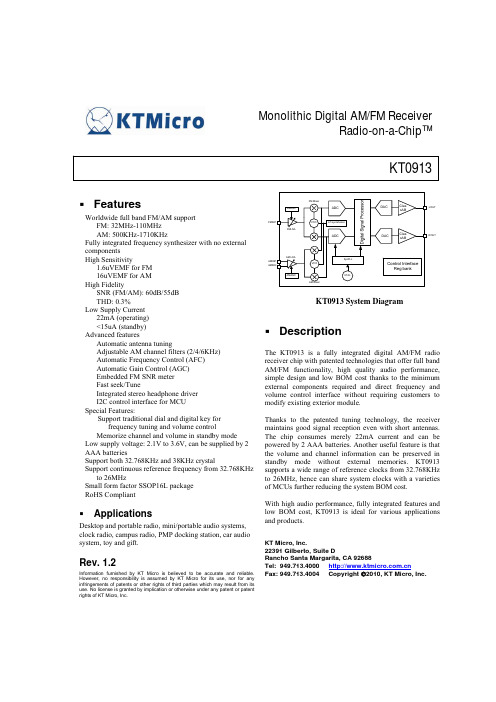
Monolithic Digital AM/FM Receiver Radio-on-a-Chip™KT0913FeaturesWorldwide full band FM/AM support FM: 32MHz-110MHz AM: 500KHz-1710KHz Fully integrated frequency synthesizer with no external components High Sensitivity 1.6uVEMF for FM 16uVEMF for AM High Fidelity SNR (FM/AM): 60dB/55dB THD: 0.3% Low Supply Current 22mA (operating) <15uA (standby) Advanced features Automatic antenna tuning Adjustable AM channel filters (2/4/6KHz) Automatic Frequency Control (AFC) Automatic Gain Control (AGC) Embedded FM SNR meter Fast seek/Tune Integrated stereo headphone driver I2C control interface for MCU Special Features: Support traditional dial and digital key for frequency tuning and volume control Memorize channel and volume in standby mode Low supply voltage: 2.1V to 3.6V, can be supplied by 2 AAA batteries Support both 32.768KHz and 38KHz crystal Support continuous reference frequency from 32.768KHz to 26MHz Small form factor SSOP16L package RoHS CompliantFMINP FMLNA FM Mixer FMAGCADCDACClas sABLOUTVCOLO syntehsizerADCDACClas sABROUTAM LNA AMINP AMINN VCOSysPLLControl Interface Reg bankAMAGC AM MixerXTALKT0913 System DiagramDescriptionThe KT0913 is a fully integrated digital AM/FM radio receiver chip with patented technologies that offer full band AM/FM functionality, high quality audio performance, simple design and low BOM cost thanks to the minimum external components required and direct frequency and volume control interface without requiring customers to modify existing exterior module. Thanks to the patented tuning technology, the receiver maintains good signal reception even with short antennas. The chip consumes merely 22mA current and can be powered by 2 AAA batteries. Another useful feature is that the volume and channel information can be preserved in standby mode without external memories. KT0913 supports a wide range of reference clocks from 32.768KHz to 26MHz, hence can share system clocks with a varieties of MCUs further reducing the system BOM cost. With high audio performance, fully integrated features and low BOM cost, KT0913 is ideal for various applications and products.KT Micro, Inc. 22391 Gilberto, Suite D Rancho Santa Margarita, CA 92688 Tel: 949.713.4000 Fax: 949.713.4004 Copyright ©2010, KT Micro, Inc.ApplicationsDesktop and portable radio, mini/portable audio systems, clock radio, campus radio, PMP docking station, car audio system, toy and gift.Rev. 1.2Information furnished by KT Micro is believed to be accurate and reliable. However, no responsibility is assumed by KT Micro for its use, nor for any infringements of patents or other rights of third parties which may result from its use. No license is granted by implication or otherwise under any patent or patent rights of KT Micro, Inc.Table of Content1. Electrical Specification............................................................................................................................ 4 2. Pin List .................................................................................................................................................... 6 3. Function Description ............................................................................................................................... 7 3.1. Overview ............................................................................................................................................. 7 3.2. FM Receiver........................................................................................................................................ 7 3.3. AM Receiver ....................................................................................................................................... 7 3.4. Operation Bands................................................................................................................................. 7 3.5. Standby ............................................................................................................................................... 7 3.6. Crystal and reference clock............................................................................................................... 8 3.7. Digital Signal Processing ................................................................................................................... 8 3.7.1. FM Stereo Decoder ........................................................................................................................ 8 3.7.2. Mute / Softmute.............................................................................................................................. 8 3.7.3. Stereo / Mono Blending ................................................................................................................. 9 3.7.4. Bass ................................................................................................................................................ 9 3.7.5. Stereo DAC, Audio Filter and Driver............................................................................................. 9 3.7.6. AM Bandwidth............................................................................................................................... 9 3.7.7. TUNE ............................................................................................................................................. 9 3.7.8. SEEK.............................................................................................................................................10 3.8. User-Machine Interface ....................................................................................................................10 3.8.1. Programmable band.......................................................................................................................10 3.8.2. Key Mode......................................................................................................................................10 3.8.3. Dial Mode......................................................................................................................................11 3.9. I2C Control Interface .......................................................................................................................13 3.10. Register Bank ....................................................................................................................................15 3.10.1. CHIP ID (Address 0x01)...............................................................................................................16 3.10.2. SEEK (Address 0x02) ...................................................................................................................16 3.10.3. TUNE (Address 0x03)...................................................................................................................16 3.10.4. VOLUME (Address 0x04) ............................................................................................................16 3.10.5. DSPCFGA (Address 0x05) ...........................................................................................................17 3.10.6. LOCFGA (Address 0x0A) ............................................................................................................18 3.10.7. LOCFGC (Address 0x0C).............................................................................................................18 3.10.8. RXCFG (Address 0x0F)................................................................................................................18 3.10.9. STATUSA (Address 0x12) ...........................................................................................................19 3.10.10. STATUSB (Address 0x13) ...........................................................................................................19 3.10.11. STATUSC (Address 0x14) ...........................................................................................................19 3.10.12. AMSYSCFG (Address 0x16)........................................................................................................20 3.10.13. AMCHAN (Address 0x17) ...........................................................................................................21 3.10.14. AMCALI (Address 0x18) .............................................................................................................21 3.10.15. GPIOCFG (Address 0x1D) ...........................................................................................................21 3.10.16. AMDSP (Address 0x22) ...............................................................................................................21 3.10.17. AMSTATUSA (Address 0x24).....................................................................................................22 3.10.18. AMSTATUSB (Address 0x25) .....................................................................................................22 3.10.19. SOFTMUTE (Address 0x2Eh)......................................................................................................22 3.10.20. USERSTARTCH (Address 0x2F).................................................................................................23 3.10.21. USERGUARD (Address 0x30).....................................................................................................23 3.10.22. USERCHANNUM (Address 0x31) ..............................................................................................23 3.10.23. AMCFG (Address 0x33) ...............................................................................................................24 3.10.24. AMCFG2 (Address 0x34h) ...........................................................................................................24 3.10.25. VOLGUARD (Address 0x3Ah) ....................................................................................................24 3.10.26. AFC (Address 0x3Ch)...................................................................................................................25 4. Typical Application Circuit ....................................................................................................................26 5. Package Outline......................................................................................................................................27 6. Revision History.....................................................................................................................................28Copyright ©2010, KT Micro, Inc.27.Contact Information................................................................................................................................28Copyright ©2010, KT Micro, Inc.31. Electrical SpecificationParameter Power Supply Ambient Temperature Symbol AVDD Ta Table 1: Operation Condition Operating Condition Min Relative to AVss 2.1 -30 Table 2: DC Characteristics Symbol Test/Operating Min Condition IFM IAM IAPD Typ 3.3 25 Max 3.6 70 Units V ℃Parameter Current Consumption Standby Current FM Mode AM ModeTyp 21.3 22 14.5Max -Units mA mA μATable 3: FM Receiver Characteristics (Unless otherwise noted Ta = -30~70℃, AVDD= 2.1V to 3.6V) Parameter Symbol Test/Operating Min Typ Max Condition FM Frequency Range Frx 110 32 Sensitivity1,2,3 Sen (S+N)/N=26dB 1.6 2 Input referred 3rd Order IIP3 85 Intermodulation Production4,5 Adjacent Channel Selectivity 35 51 ±200KHz Alternate Channel Selectivity 50 70 ±400KHz Image Rejection Radio 35 AM suppression 50 RCLK frequency 32.768 32.768 26000 RCLK frequency Range8 -100 100 Audio Output Voltage1,2,3,4 32ohm load 90 100 110 Audio Band Limits1,2,4 30 15k ±3dB 1,4,6 Audio Stereo Separation 35 Audio Mono S/N1,2,3,4 55 60 Audio Stereo S/N1,4,6,7 DBLND=1 64 Audio THD1,2,4,6 0.3 De-emphasis Time Constant DE=0 75 DE=1 50 Audio Common Mode Voltage 0.85 Audio Output Load Resistance RL Single-ended 32 Seek/Tune Time 50 Power-up Time 600 Notes: 1. FMOD=1KHz, 75us de-emphasis 2. MONO=1 3. △F=22.5KHz 4. VEMF=1mV, Frequency=32MHz~110MHz 5. AGCD=1 6. △F=75KHz 7. VOLUME<4:0>=11111 8. The supported RCLK frequency is not continuous. Please refer to application notes.Units MHz uVemf dBuVE MF dB dB dB dB KHz ppm mVRMS Hz dB dB dB % μs μs V Ω ms msCopyright ©2010, KT Micro, Inc.4Table 4: AM Receiver Characteristics (Unless otherwise noted Ta = -30~70℃, AVDD= 2.1V to 3.6V) Parameter Symbol Test/Operating Min Typ Condition AM Frequency Range Frx 500 Sensitivity1,2 Sen (S+N)/N=26dB 15 Audio Output Voltage1,2,3,4 32ohm load 60 Audio Mono S/N1,2,3,4 55 Audio THD1,2,4,6 0.3 Antenna inductance L 280 350 Notes: 1. FMOD=1KHz 2. Modulation index is 30% 3. VEMF=1mV, Frequency=500KHz~1710KHz 4. VOLUME<4:0>=11111Max 1710Units KHz uVemf mVRMS dB % uH0.6 420Copyright ©2010, KT Micro, Inc.52. Pin ListTable 5: Pin listPin Num 1 2 3 4 5 6 7 8 9 10 11 12 13 14 15 16Pin Name CH DVSS ROUT LOUT AVSS AVDD XI/RCLK XO ENABLE AMINN AMINP RFINP RFGND SCL SDA VOLDescription Channel adjustment. Digital ground. Right channel audio output. Left channel audio output. Analog ground. Power supply. Crystal input/Reference clock input. Crystal output. Chip enable. Tied to an internal 600kohm pull down resistor. AM RF negative input. AM RF positive input. FM RF input. RF ground. SCL of I2C interface. Tied to an internal 47kohm pull-up resistor. SDA of I2C interface. Tied to an internal 47kohm pull-up resistor. Volume adjustment.Figure 1: KT0913 Pin assignment (Top view)Copyright ©2010, KT Micro, Inc.63. Function Description3.1. OverviewKT0913 offers a true single-chip, full-band FM/AM and versatile radio solution by minimizing the external components and offering a variety of configurations.3.2. FM ReceiverKT0913 enters FM mode by setting register AM_FM to 0. The FM receiver is based on the architecture of KT Micro’s latest generation FM receiver chips in mass production. There are no external filters or frequency-tuning devices thanks to a proprietary digital low-IF architecture consisting of a fully-integrated LNA, an automatic gain control (AGC), a set of high-performance ADCs, high-quality analog and digital filters, and an on-chip low-noise self-tuning VCO. The on-chip high-fidelity Class-AB driver further eliminates the need for external audio amplifiers and can drive stereo headphones directly.3.3. AM ReceiverKT0913 enters AM mode by setting register AM_FM to 1. The AM Receiver employs a similar digital low IF architecture and share many circuits with the FM receiver. The AM receiver supports a wide band from 500KHz to 1710KHz also known as the popular AM bands. The AM channel spacing can be set to 1KHz, 9KHz or 10KHz to address different applications. The bandwidth of the channel filter can be set to 2KHz, 4KHz or 6KHz to suit various requirements. The AM receiver in KT0913 can provide accurate and automatic AM tuning without manual alignment. It supports 350uH ferrite loop antenna with +/- 25% tolerance.3.4. Operation BandsKT0913 supports wide FM band and AM bands. The FM receiver covers frequencies from 32MHz to 110MHz. The 32MHz to 64MHz is defined as Campus Band in KT0913 and can be enabled by setting CAMPUSBAND_EN register to 1. The AM band is from 500KHz to 1710KHz.3.5. StandbyKT0913 supports both Software Standby mode and Hardware Standby mode. To enter Software Standby, the STANDBT register shall be set to 1 through I2C interface. To enter Hardware Standby, the ENABLE pin is pulled down to ground. In the standby modes, the internal state (channel, volume) is preserved and can be recovered when the chip wakes up from the standby.Copyright ©2010, KT Micro, Inc.73.6. Crystal and reference clockKT0913 integrates a low frequency crystal oscillator that supports 32.768KHz and 38KHz crystals. Alternatively a CMOS level external reference clock may be used by setting the RCLK_EN register to 1 and setting REFCLK<3:0> according to the frequency of the reference clock.3.7. Digital Signal Processing3.7.1. FM Stereo DecoderThe digitized IF signal is fed to the FM demodulator which demodulates the signal and outputs a digital multiplexed (MPX) signal consisting of L+R audio, L-R audio, 19KHz pilot tone and RDS signal. The left channel signal and the right channel signal can be extracted from the MPX signal by simply adding and subtracting the L+R signal and L-R signal. The spectrum diagram is shown in Figure 2.Figure 2: Spectrum diagram of the MPX signal3.7.2. Mute / SoftmuteKT0913 can be hard muted by setting DMUTE to 0 and the output of the audio signal is set to the common mode voltage. There is also a Soft Mute feature that is enabled by setting FMDSMUTE to 0 in FM mode and AMDSMUTE to 0 in AM mode. In this mode, the audio volume is gradually attenuated when the signal reception is bad (i.e. when the RSSI is below a certain level as defined by FM_SMTH<2:0> and AM_SMTH<2:0>, respectively.) The attenuation attack rate and depth can be configured through SMUTER<1:0> and SMUTEA<1:0>, Copyright ©2010, KT Micro, Inc. 8respectively. The target volume can be configured through VOLUMET<4:0>. SNR value can also be used as the judgment threshold in FM mode by setting SMMD to 1.3.7.3. Stereo / Mono BlendingIn order to provide a comfortable listening experience, KT0913 blends the stereo signal with mono signal gradually when in weak reception in FM mode. The signal level range over which the blending occurs is set by BLNDADJ<1:0>. The blending is disabled when DBLND is set to 1. MONO playback mode can be forced by setting the MONO to 1. If the MONO bit and the INV_LEFT_AUDIO bit are both set to 1, then a fully differential signal will be output at the LOUT and ROUT.3.7.4. BassKT0913 provides bass boost feature for audio enhancement. The gain of the bass boost can be programmed through BASS<1:0>. With BASS<1:0>=00, this feature is disabled.3.7.5. Stereo DAC, Audio Filter and DriverTwo high-quality single-bit ΔΣ audio digital-to-analog converters (DAC) are integrated along with high-fidelity analog audio filters and class AB drivers. Headphones with impedance as low as 16ohms can be directly driven without adding external audio drivers. An integrated anti-pop circuit suppresses the click-and-pop sound during power up and power down. For different load capacitor, user can set different anti-pop configuration through POP<1:0>.3.7.6. AM BandwidthKT0913 provide programmable AM channel bandwidth through AM_BW<1:0>.3.7.7. TUNEThe fully integrated LO synthesizer supports wide band operation. Channel tuning is started when the register AMTUNE/FMTUNE is set to 1. In FM mode, the channel frequency is set by FMCHAN<11:0> and is defined as Freq(MHz) = 50KHz × FMCHAN<11:0> In AM mode, the channel frequency is set by AMCHAN<10:0> and is defined as Freq(KHz) = 1KHz × AMCHAN<10:0>Copyright ©2010, KT Micro, Inc.93.7.8. SEEKKT0913 offers an effective software based seek algorithm. Refer to application notes for more information.3.8. User-Machine InterfaceChannel and volume can be adjusted not only by setting corresponding FMCHAN, AMCHAN and VOLUME registers, but also by using built-in user-machine interface. Two types of user-machine interface, Key Mode and Dial Mode, are provided by KT0913. In these modes, the channel and volume are controlled by KT0913 itself.3.8.1. Programmable bandKT0913 supports programmable arbitrary frequency range of the operation band by setting register USERBAND to 1. Information of the current band, such as AM/FM mode, upper and lower edge of the band, channel step and the number of guard channel used in Dial Mode, should be written to KT0913 once the band is chosen, which is sensed by MCU. The number of channels and start channel are defined in register USER_CHAN_NUM<11:0> and USER_START_CHAN<14:0>. In FM mode, where register AM_FM is set to 0, the lower and upper bound of the current band can be express as: f bot = USER _ START _ CHAN < 14 : 0 > ×50 KHzf top = f bot + USER _ CHAN _ NUM < 11 : 0 > × f step Where f step is the channel step, which can be configured by register FMSPACE<1:0>. In AM mode, where register AM_FM is set to 1, the corresponding lower and upper bound of the band are: f bot = USER _ START _ CHAN < 14 : 0 > ×1KHzf top = f bot + USER _ CHAN _ NUM < 11 : 0 > × f stepWhere f step is the channel step, which can be configured by register AMSPACE<1:0>.3.8.2. Key ModeKT0913 allows user to control the channel and volume by using keys/buttons to send digital control signals to CH and VOL pins. Please refer to Section 4 for a typical application circuit. The key mode is enabled by setting GPIO1<1:0> and GPIO2<1:0> to 01.Copyright ©2010, KT Micro, Inc.10Each time VOLP/VOLM key is pressed, the volume increases/decreases by 2dB. If the VOLP/VOLM key is pressed and held, the volume will continue to increase/decrease at 2dB steps until the key is released. When configured in Key Mode, KT0913’s channel selection has two working modes. Mode A: If KEY_MODE<1:0> is set to 00, Mode A is selected. In this mode, each time the CHP (CHM) is pressed, the channel frequency increases (decreases) by one step. The step sizes are defined by FMSPACE<1:0> and AMSPACE<1:0>. If the CHP (CHM) key is pressed for and held for a certain time (defined by TIME1<1:0>), the channel frequency will continue to increase (decrease) automatically at a certain pace (as defined by TIME2<2:0>) until the key is released. Mode B: If KEY_MODE<1:0> is set to 01, Mode B is selected. In this mode, each time the CHP (CHM) is pressed, the channel increases (decreases) by one step. The step sizes are defined by FMSPACE<1:0> and AMSPACE<1:0>. If the CHP (CHM) key is pressed and held for a specific time (TIME1<1:0>), the channel will continue to increase (decrease) automatically at a certain pace (TIME2<2:0>) even if the key is released. The movement is stopped when the key is pressed again.3.8.3. Dial ModeKT0913 supports a unique Dial Mode whose application circuit is shown in Figure 3. The dial is implemented by a variable resistor with the center tap connected to the chip. KT0913 measures the divider ratio of two parts of the variable resistor and maps the result to the real control parameters, such as channel frequency, volume, etc. The channel controller enters dial mode by setting register GPIO1<1:0> to 10. The illustration circuit is shown in Figure 3 错误!未找到引用源。
阿美泰克2014样本

page 02
板式换热器特点
page 03
板式换热器系列
Plate heat exchanger
板式换热器系列
Plate heat exchanger
板式换热器特点
先进的板型设计
上海阿美泰克公司引进了AMETECH的先进设计、制造生产工艺,以用户使用的 可靠性与最佳运行性能为核心,最大限度提高换热效率,降低能耗损失。
板式换热器系列
Plate heat exchanger
板式换热器系列
Plate heat exchanger
等截面板式换热器型号及意义 A M 20–MPM /6000 - 100
换热量(kw)- 换热面积(m2)
压力等级
PL:1.0 MPa PM:1.6MPa PG:1.6~2.5MPa
波纹深度
M:深波纹 B:浅波纹
管壳式换热器………………………………………………………………………………………………………………………25
容积式换热器………………………………………………………………………………………………………………………27
半即热式换热器……………………………………………………………………………………………………………………29
板式换热器的结构原理板式换热器材质技术规范和质量保证体系美国asme日本jis标准美国3a卫生标准德国tuv标准中国nbt47004iso90011400118000板片材质材料型号适用场合耐酸耐热不锈钢工业纯钛哈氏合金镍基合金超级铁素体工业黄铜sus304sus316lta1ta2hastelloyc276c2000n6c4000cr18mo2000cr26mo1h68河水盐水海水和有氯离子腐蚀场合浓硫酸盐酸磷酸及强氧化性介质等场合高温高浓度苛性钠和有氯离子腐蚀场合有机溶剂和有晶间腐蚀氯离子腐蚀场合海水低温冷冻场合净水河川水食用油矿物油酸碱介质和腐蚀较严重的场合不适宜有氯离子的场合垫片材质使用温度适用介质场合丁腈橡胶nbr氯丁橡胶neoprene三元乙丙橡胶epdm氟橡胶vitonfpm硅橡胶siliconerubber水氟里昂等一般弱酸弱碱腐蚀的场合高温热水和蒸汽
AS-PS02 AS-PS02A 安裝說明说明书
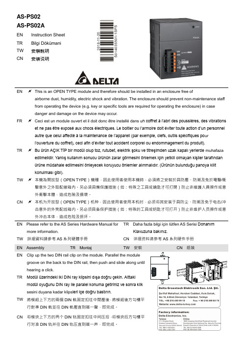
AS-PS02AS-PS02AEN Instruction SheetTR Bilgi DökümaniTW安裝說明CN安装说明EN This is an OPEN TYPE module and therefore should be installed in an enclosure free of airborne dust, humidity, electric shock and vibration. The enclosure should prevent non-maintenance staff from operating the device (e.g. key or specific tools are required for operating the enclosure) in casedanger and damage on the device may occur.FR Ceci est un module ouvert et il doit donc être installé dans u n coffret à l’abri des poussières, des vibrations et ne pas être exposé aux chocs électriques. Le boitier ou l’armoire doit éviter toute action d’un personnel autre que celui affecté à la maintenance de l’appareil (par exemple, clefs, outils spécifiques po url’ouverture du coffret), ceci afin d’éviter tout accident corporel ou endommagement du produit).TR Bu ürün AÇIK TİP bir modül olup toz, rutubet, elektrik şoku ve titreşimden uzak kapalı yerlerde muhafaza edilmelidir. Yanlış kullanım sonucu ürünün zarar görmesini önlemek için yetkili olmayan kişiler tarafındanürüne müdahale edilmesini önleyecek koruyucu önlemler alınmalıdır. (Ürünün bulunduğu panoya kilitkonulması gibi).TW 本機為開放型(OPEN TYPE)機種,因此使用者使用本機時,必須將之安裝於具防塵、防潮及免於電擊∕衝擊意外之外殼配線箱內。
SA8000-2014(中英文本实用标准化)

Social Accountability 80002014版SA8000 国际标准(最新英中文本)International Standard by Social Accountability InternationalJune 2014SA8000®: 2014Supersedes previous versions: 2001, 2004 and 2008The official language of this Standard and supporting documents is English. In the case of inconsistency between versions, reference shall default to the English version.Contents 容I. INTRODUCTION 前言1. Intent and Scope 目的与围2. Management System 管理体系II. NORMATIVE ELEMENTS AND THEIR INTERPRETATION 规性原则及其解释III. DEFINITIONS 定义IV. SOCIAL ACCOUNTABILITY REQUIREMENTS 社会责任规1. Child Labour 童工2. Forced or Compulsory Labour强迫或强制性劳动3. Health and Safety 健康与安全4. Freedom of Association & Right to Collective Bargaining 自由结社及集体谈判权利5. Discrimination 歧视6. Disciplinary Practices 惩戒性措施7. Working Hours 工作时间8. Remuneration 工资9. Management System 管理体系I.INTRODUCTION 前言1. Intent and Scope 目的与围Intent: The intent of SA8000 is to provide an auditable, voluntary standard, based on the UN Declaration of Human Rights, ILO and other international human rights and labour norms and national labour laws, to empower and protect all personnel within an organisation’s control and influence who provide products or services for that organisation, including personnel employed by the organisation itself and by its suppliers, sub-contractors, sub-suppliers and home workers. It is intended that an organisation shall comply with this Standard through an appropriate and effective Management System.目的:本标准目的在于提供一个基于联合国人权宣言,国际劳工组织(ILO)和其他国际人权惯例,劳动定额标准以及国家法律的标准,授权并保护所有在公司控制和影响围的生产或服务人员,包括公司自己及其供应商,分包商,分包方雇用的员工和家庭工人。
EK260体积修正仪

● 250 个事件纪录(例如状态改变、信号输入、超标状态); ● 由操作的先后顺序,保留最后的 200 步操作; 2 操作 2.1 前面板 下面是对前面板进行操作的说明 ● 两行字符高度的字符/数字型显示器,每行可以显示 16 个字符; ● 在面板上安装有 6 个按键完成显示和输入功能;
失调体积、总量计数器、可调计数器、测量间隔计数器以及日计数器); ● 每个正式调整后的输入都被铅封保护; 脉冲/数字信号输出 ● 四个可编程的晶体管输出,每个都可以独立的被编程为警告/变更输出、
脉冲输出、限值输出;
1 本文将 Calibration Lock 翻译成标定锁 2 本文将 Supply Lock 翻译成供方锁 3 本文将 Custome封装保护; 数据接口 ● 红外接口符合 IEC1107 规范; ● RS232 接口; 压力传感器 ● 内置的 CT30 或者 PDCR900 压力传感器; 温度传感器 ● PT500 温度传感器,型号为 EBL50 或者 EBL160; 机械结构 ● 适合安装在墙立面和流量计上(使用安装支架); ● 支架+流量计的安装方式可以不破坏密封; ● 环境温度范围:-20℃—+60℃(使用 CT30 压力传感器),
环境温度超出上述范围仪器的功能受到限制; 许可证 ● 认证通过
—适用于气体体积修正仪 —适用于大流量流量计的显示 ● 仪器被批准应用于防爆Ⅰ区符合防爆标识达到防爆标准、本安防爆形式、 防爆等级达到 ibⅡC 标准,防爆温度等级达到 T4 标准。 监测功能 ● 监测数字量输入; ● 监测超标状态(限值可以预先设置); 记录功能 ● 最多可以记录 15 个月的 Vb 和 V 数据; ● 作为影响气体定律偏差和转化的部分因素记录 15 个月以来温度和压力 的最小值、最大值和平均值信息; ● 在测试间隔在 60 分钟的情况下,可以保留 9 个月的 Vb、V、p、T、K 和 C 的测量信息。测试时间间隔可以从 1 到 60 分钟之间调整。 ● 自动调整夏时制功能;
Definitions of CEC2014 benchmark suite Part A

function and each basic function. Considering that in the real-world problems, it is seldom that there exist linkages among all variables. In CEC’14 the variables are divided into subcomponents randomly. The rotation matrix for each subcomponents are generated from standard normally distributed entries by Gram-Schmidt ortho-normalization with condition number c that is equal to 1 or 2.
J. J. Liang1, B. Y. Qu2, P. N. Suganthan3
2
School of Electrical Engineering, Zhengzhou University, Zhengzhou, China School of Electric and Information Engineering, Zhongyuan University of Technology, Zhengzhou, China
oi1 [oi1 , oi 2 ,..., oiD ]T : the shifted global optimum (defined in “shift_data_x.txt”), which is
randomly distributed in [-80,80]D. for CEC’14.
Different from CEC’13, each function has a shift data
SA_2015_05(Styles-3)

Knowledge Sources
Objective:
contribute knowledge that leads to solution(提供解决问题的 知识) procedures, sets of rules, logic assertions(过程、规则、逻辑 断言) modify only the blackboard (or control data -- magic)(只修 改黑板) know when it’s possible to help(知道何时能发挥作用) loosely-coupled subtasks, or areas of specialization(低耦合的 子任务,或者有特别的能力)
根据所使用的控制策略不同,数据共享体系结构可以分为 两种类型:
一种是传统的数据库,另一种是黑板。
2
Xidian University, Xi’an, China © 2015
Repository Architecture
3
Xidian University, Xi’an, China © 2015
决问题)
various domain expertise required to solve the problem(需要
多个领域的专门知识协作解决)
uncertainty
error and variability in data and solution(数据和解决方法可能
错误或变化)
moderate to low “signal-to-noise-ratio” in data(数据中信噪比
Xidian University, Xi’an, China © 2015
- 1、下载文档前请自行甄别文档内容的完整性,平台不提供额外的编辑、内容补充、找答案等附加服务。
- 2、"仅部分预览"的文档,不可在线预览部分如存在完整性等问题,可反馈申请退款(可完整预览的文档不适用该条件!)。
- 3、如文档侵犯您的权益,请联系客服反馈,我们会尽快为您处理(人工客服工作时间:9:00-18:30)。
Data Flow Call/Return Data-centered Virtual Machine Independent Component
Other styles
2
Xidian University, Xi’an, China © 2014
Architectural Styles
A style
Xidian University, Xi’an, China © 2014
10
Agenda
What is software architecture style? Taxonomy of style
Data Flow Call/Return Data-centered Virtual Machine Independent Component
6
Xidian University, Xi’an, China © 2014
Taxonomy of Styles
Garlan和Shaw给出了通用体系结构风格的分类(a list of common architectural styles)
7
Xidian University, Xi’an, China © 2014
Code reuse
Understandability of system organization
Interoperability(互操作)
Style-specific analyses
Visualizations
4
Xidian University, Xi’an, China © 2014
要研究近似线性数据流)
or in very simple, highly constrained cyclic structures(或者是在限度内
的循环数据流)
15
Xidian University, Xi’an, China © 2014
Control Flow vs. Data Flow
2. Software Architecture Style
(软件体系结构风格)
Xidian University, Xi’an, China © 2014
Agenda
What is software architecture style? Taxonomy of styles
is a package of design decisions(是若干设计思想的综合) has known properties that permit reuse(具有已经被熟知的特 性,并且可以复用)
3
Xidian University, Xi’an, China © 2014
Benefits of Using Styles
融合很多体系风格的特色)
as an architect you must understand the “pure” styles to understand the strength and weaknesses of the style as well as the consequences of deviating from the style(作为一个架构师,你必须
单元便开始工作)
Data Flow
We reason about data availability, transformations, latency, …(我们关心数据是否可用,转换,延时……)
In a pure data flow system, there is no other interaction between processes(在纯数据流系统中,处理之间除了数据交
换,没有任何其他的交互)
Xidian University, Xi’an, China © 2014
12
Data Flow Style
Xidian University, Xi’an, China © 2014
Systems
14
Patterns of Data Flow in Systems
In general, data can flow in arbitrary patterns(一
般情况,数据的流向无序)
Often we are primarily interested in nearly linear data flow systems(我们主
Control Flow (typical case in procedural systems)
Dominant question is how locus of control moves through the program(主要问题是控制点怎样在程序或系统之间移动) Data may accompany the control but is not the driving force (数据可能跟着控制走,但是并不起推动系统运转的作用) Primary reasoning is about order of computation(关注的核 心是计算顺序) Dominant question is how data moves through a collection of (atomic) computations(主要问题是数据怎样在运算单元之间流动) As data moves, control is “activated”(数据到了,控制(计算)
Other styles
11
Xidian University, Xi’an, China © 2014
Data Flow Style
A data flow system is one in which
the availability of data controls the computation(由数据控制 计算) the structure of the design is dominated by orderly motion of data from process to process(系统结构由数据在处理之间的有 序移动决定) the pattern of data flow is explicit(数据流系统的结构是显而 易见的)
Notes about Architecture Styles
When we introduce a new style, we will typically first examine its “pure” form.
pure architectural style are rarely found in practice(纯粹的体系风
describes a class of architectures(描述一类体系结构) is independent on the problems(独立于实际问题,强调了软件 系统中通用的组织结构)
is found repeatedly in practice(在实践中被多次设计、应用)
5
Style Analysis Dimensions
What is the design vocabulary(设计词汇表)?
Component and connector types
What are the allowable structural pattern? What is the underlying computational model? What are the essential invariants(基本不变性) of the style? What are some common examples of its use? What are the advantages and disadvantages of using that style? What are some of the common specializations?
理解“纯”的风格。理解它的优点与缺陷,也要理解背离此种风格之后 会带来什么结果)
8
Xidian University, Xi’an, China © 2014
Notes about Architecture Styles
There is no complete list(没有完备的列表) Styles overlap(风格是彼此重叠的) Systems exhibit multiple styles at once(一个系统通常表现 出多种风格)
13
Xidian University, Xi’an, China © 2014
Data Flow Styles
Components: Data Flow Components
Interfaces are input ports and output ports(组件接口是输入 端口和输出端口) Computational model: read data from input ports, compute, write data to output ports(计算模型:从输入端读数据,计 算,将计算结果写到输出端) Uni-directional(单向)
Connectors: Data Streams
usually asynchronous, buffered (通常是异步的,有缓冲)
Interfaces are reader and writer roles Arbitrary graphs(任意拓扑结构) Computational model: functional composition