JAN2N5682中文资料
JANTXV2N6796U中文资料

— 45
1.8 — 4.3 —
nH
Measured from drainpadto Modified MOSFET symbol show-
die.
ing the internal inductances.
Measured from center of source pad to the end of source bonding wire.
Product Summary
Part Number
BVDSS
IRFE130
100V
RDS(on) 0.18Ω
Features:
n Hermetically Sealed n Simple Drive Requirements n Ease of Paralleling n Small footprint n Surface Mount n Lightweight
HEXFET transistors also feature all of the well-established advantages of MOSFETs, such as voltage control, very fast switching, ease of paralleling and electrical parameter temperature stability. They are well-suited for applications such as switching power supplies, motor controls, inverters, choppers, audio amplifiers and high-energy pulse circuits, and virtually any application where high reliability is required.
JANTXV2N6788U中文资料

TJ TSTG
Operating Junction Storage Temperature Range Pckg. Mounting Surface Temp.
Weight
For footnotes refer to the last page
LCC-18
Features:
n Surface Mount n Small Footprint n Alternative to TO-39 Package n Hermetically Sealed n Dynamic dv/dt Rating n Avalanche Energy Rating n Simple Drive Requirements n Light Weight
Note: Corresponding Spice and Saber models are available on International Rectifier Website. For footnotes refer to the last page
2
元器件交易网
15V
VDS
L
DRIVER
RG
2V0GVS tp
D.U.T IAS
0.01Ω
+ - VDD
A
Fig 12a. Unclamped Inductive Test Circuit
V(BR)DSS tp
Fig 12c. Maximum Avalanche Energy Vs. Drain Current
IAS
Thermal Resistance
Parameter
RthJC RthJ-PCB
Junction to Case Junction to PC Board
2N5886中文资料
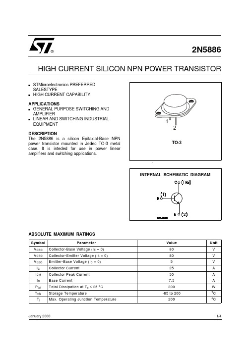
2N5886HIGH CURRENT SILICON NPN POWER TRANSISTORsSTMicroelectronics PREFERRED SALESTYPEsHIGH CURRENT CAPABILITYAPPLICATIONS s GENERAL PURPOSE SWITCHING AND AMPLIFIERs LINEAR AND SWITCHING INDUSTRIAL EQUIPMENT DESCRIPTION The 2N5886 is a silicon Epitaxial-Base NPN power transistor mounted in Jedec TO-3 metal case. It is inteded for use in power linear amplifiers and switching applications.January 2000ABSOLUTE MAXIMUM RATINGS®1/42N5886THERMAL DATAC unless otherwise specified)ELECTRICAL CHARACTERISTICS (T case = 25 o2N5886Information furnished is believed to be accurate and reliable. However, STMicroelectronics assumes no responsibility for the consequences of use of such information nor for any infringement of patents or other rights of third parties which may result from its use. No license is granted by implication or otherwise under any patent or patent rights of STMicroelectronics. Specification mentioned in this publication are subject to change without notice. This publication supersedes and replaces all information previously supplied. STMicroelectronics products are not authorized for use as critical components in life support devices or systems without express written approval of STMicroelectronics.The ST logo is a trademark of STMicroelectronics© 2000 STMicroelectronics – Printed in Italy – All Rights ReservedSTMicroelectronics GROUP OF COMPANIESAustralia - Brazil - China - Finland - France - Germany - Hong Kong - India - Italy - Japan - Malaysia - Malta - Morocco - Singapore - Spain - Sweden - Switzerland - United Kingdom - U.S.A.2N5886。
交叉电缆

交叉电缆
所谓“交叉线”,是指一头使用568A标准,另一头使用568B标准;非交叉线,即“直通线”,是指两端使用同一种标准。
交叉电缆一般用来实现相同类型的设备,如集线器到集线器、集线器到交换机、路由器到路由器、交换机到交换机或PC机到PC机的连接。
中文名
交叉电缆
外文名
crossover cable
交叉与不交叉,所使用的网线都是一样的,只是在压线头的时候次序不同而已。
所谓“交叉线”,是指一头使用568A标准,另一头使用568B标准;非交叉线,即“直通线”,是指两端使用同一种标准。
标准568A:绿白-1,绿-2,橙白-3,蓝-4,蓝白-5,橙-6,棕白-7,棕-8。
标准568B:橙白-1,橙-2,绿白-3,蓝-4,蓝白-5,绿-6,棕白-7,棕-8;
一般来说,相同设备相连接,使用交叉线。
但如果处于下端的设备上有“UPLINK”接口,则可以使用直通线通过“UPLINK”接口与上端设备连接。
另外,一些新的设备,具有端口识别功能,能自动识别是平行线还是交叉线,那就无所谓。
交叉电缆一般用来实现集线器到集线器、集线器到交换机、路由器到路由器、交换机到交换机或PC机到PC机的连接。
568 EX红外测温仪使用手册说明书
568 EXInfrared Thermometer PN 4326622June 2013© 2013 Fluke Corporation. All rights reserved.Specifications are subject to change without notice.All product names are trademarks of their respective companies.LIMITED WARRANTY AND LIMITATION OF LIABILITY This Fluke product will be free from defects in material and workmanship for two years from the date of purchase. This warranty does not cover fuses, disposable batteries, or damage from accident, neglect, misuse, alteration, contamination, or abnormal conditions of operation or handling. Resellers are not authorized to extend any other warranty on Fluke’s behalf. To obtain service during the warranty period, contact your nearest Fluke authorized service center to obtain return authorization information, then send the product to that Service Center with a description of the problem.THIS WARRANTY IS YOUR ONLY REMEDY. NO OTHER WARRANTIES, SUCH AS FITNESS FOR A PARTICULAR PURPOSE, ARE EXPRESSED OR IMPLIED. FLUKE IS NOT LIABLE FOR ANY SPECIAL, INDIRECT, INCIDENTAL OR CONSEQUENTIAL DAMAGES OR LOSSES, ARISING FROM ANY CAUSE OR THEORY. Since some states or countries do not allow the exclusion or limitation of an implied warranty or of incidental or consequential damages, this limitation of liability may not apply to you.Fluke CorporationP.O. Box 9090 Everett, WA 98206-9090 U.S.A. Fluke Europe B.V. P.O. Box 1186 5602 BD Eindhoven The Netherlands11/99Table of ContentsTitle Page Introduction (1)Safety Information (2)Features (5)Display (5)Menu Overview (6)Save (7)Light (7)Memory (7)Emissivity Menu (7)°C and °F (9)Min, Max, Avg, Differential (9)Alarm (9)Trigger Lock (10)Laser (10)Setup (11)Language (11)Backlight (11)Time/Date (12)Delete Data (13)How the Product Works (13)Product Operation (14)Temperature Measurement (14)Find a Hot or Cold Spot (14)Distance and Spot Size (15)i568 EXUsers ManualField of View (16)HOLD (17)External Contact Probe (18)Troubleshooting (18)Maintenance (19)Battery Replacement (19)Clean the Lens (19)Clean the Case (19)Replacement Parts (19)Specifications (20)General Specifications (20)KTC Specifications (21)iiIntroductionThe 568 EX Infrared Thermometer (the Product) is designed for operation in potentially explosive areas of Zones 2 and 1 in accordance with Directive 1999/92/EC respectively 94/9/EC (ATEX).Contact FlukeTo contact Fluke, call one of the following telephone numbers: •Technical Support USA: 1-800-44-FLUKE (1-800-443-5853) •Calibration/Repair USA: 1-888-99-FLUKE (1-888-993-5853) 1-800-36-FLUKE(1-800-363-5853)• Canada:•Europe: +31 402-675-200+81-3-3434-0181• Japan:+65-738-5655• Singapore:•Anywhere in the world: +1-425-446-5500Or, visit Fluke's website at .To register your product, visit .To see, print, or download the latest manual supplement, visit /usen/support/manuals.1568 EX Users Manual2Safety InformationThe current operating instructions, EC Declaration of Conformityand the Ex-certificate are available for download from the relevantproduct page under ; alternatively they can berequested directly from the manufacturer.A Warning identifies conditions and procedures that aredangerous to the user.Symbols used on the Product and in this manual are explained inTable 1. Laser safety markings are shown in Figure 1.NoteFor special safety information for use in ex-hazardousareas, please see the additional Safety Instructions.WarningTo prevent possible electrical shock, fire, eyedamage, or personal injury:•Read all safety information before you use the Product. • Use the Product only as specified, or the protection supplied by the Product can becompromised.• Do not use the product if it operates incorrectly.•See emissivity information for actual temperatures. Reflective objects result in lowerthan actual temperature measurements. Theseobjects pose a burn hazard.Infrared ThermometerSafety Information3• Do not look directly into the laser with optical tools (for example, binoculars, telescopes,microscopes). Optical tools can focus the laserand be dangerous to the eye.• Do not look into the laser. Do not point laserdirectly at persons or animals or indirectly offreflective surfaces.• Use the Product only as specified or hazardouslaser radiation exposure can occur.568 EX Users Manual4 Table 1. SymbolsSymbol ExplanationHazardous voltage. Risk of electrical shock.Risk of danger. Important information. See manual.Warning.Laser.Conforms to European Union directives.°C Celsius°F FahrenheitBatteryThis product complies with the WEEE Directive (2002/96/EC) marking requirements. The affixed label indicates that you must not discard this electrical/electronic product in domestic household waste. Product Category: With reference to the equipment types in the WEEE Directive Annex I, this product is classed as category 9 "Monitoring and Control Instrumentation” product. Do not dispose of this product as unsorted municipal waste. Go to Fluke’s website for recycling information.BatteryFigure 1. Laser Safety MarkingsInfrared Thermometer Features 5Features• Single-spot laser sighting• Backlight display• MAX, MIN, DIF, and AVG temperature display• 80PK-1 K-type thermocouple (KTC) probe• Adjustable emissivity and predefined emissivity table• Infrared and thermocouple temperature display• Celsius or Fahrenheit temperature display• Tripod mount• Standard miniature KTC connector input• 12 or 24 hour clock• Last reading Hold (20 seconds) and auto off• Multi-language interface• High and low temperature alarm• Data storage and review• Trigger lockDisplayThe Product display can show data in these languages:• English• German• French• Portuguese• Simplified Chinese568 EX Users Manual6 Menu OverviewFigure 2 shows the LCD and menu interface. Table 2 is a top-leveldescription of the menu.Figure 2. Menu NavigationTable 2. Top-Level Menu Description Level Softkey Description1 Left Save Save reading to memory2 Left Mem Review/delete memory entries3 Left MnMx Enable Min/Max4 Left °C/°F Toggle between C and F5 Left (Lock) Lock the Product on6 Left Setup Turn off/on backlight1 Right Light Adjust backlight brightness2 Right Set emissivity3 Right Avg Enable Avg/Diff4 Right Alarm Set and enable alarms5 Right Laser Toggle the laser on/offAll Center Menu Advance the menu to the next levelDisplaySaveTo save readings:1. Pull the trigger to take a measurement and release it to stop.Save softkey to enter the Save menu.the2. PushYes softkey to save the reading.3. PushtheThe saved reading includes:temperature• IR•Thermocouple temperature (if connected)• EmissivityMin/Max or Avg/Dif is enabled)(if• Min/Max/Avg/Dif• Date/TimeYou can push the Cancel softkey to stop saving the reading.LightThe Product has a backlight display with two brightness levels.To toggle the backlight brightness, push the Light softkey.To disable the backlight, use the Setup menu.MemoryThe Product can store up to 99 measurement records.To access records stored in memory, push the Menu softkey untilMem shows as the left softkey, and then push the Mem softkey toaccess the Memory menu.Emissivity MenuThe Emissivity menu includes a list of pre-defined materials andlists their typical emissivity values. See Table 3 for furtherinformation.Users ManualNoteDefault emissivity is 0.95.Table 3. Nominal Surface EmissivityMaterial Value Material ValueDefault**** 0.95Glass 0.85Aluminum* 0.30 Iron* 0.70Lead* 0.50 Asbestos 0.95Oil 0.94 Asphalt 0.95Brass* 0.50 Paint 0.93Plastic** 0.95Ceramic 0.950.95Concrete 0.95RubberCopper* 0.60 Sand 0.90Food - Frozen 0.90 Steel* 0.80Food - Hot 0.93 Water 0.93Wood 0.94* Oxidized** Opaque, over 20 mils*** Natural**** Factory SettingHighlighted items may also be found in the emissivity table builtinto the Product.To access the Emissivity menu:Menu softkey until shows as the right softkey the1. Pushsoftkey.2. PushtheTo access the Emissivity list:1. PushTable softkey. The display shows a list of materials theand their suggested emissivity.2. Use the down arrow to navigate through the list.Display Enter softkey to choose the necessary material.the3. PushTo manually type the typical emissivity of a material:theNo. softkey.1. Push2. Use the down or up arrow softkey to change the entry. Holddown the arrow softkeys to increase the rate of change.Done softkey to return to the main menu.the3. Push°C and °FTo toggle between °C and °F measurements, push the Menusoftkey until °C or °F shows as the left softkey, and then push thenecessary softkey.Min, Max, Avg, DifferentialThe Product can measure minimum (MIN), maximum (MAX),average (AVG), or differential (Δ) temperatures. The Product doesnot show these values if a thermocouple is connected to it.To turn on the Min/Max and Avg/Diff modes:theMenu softkey until MnMx shows as the left softkey1. Pushand Avg shows as the right softkey.theMnMx softkey and the Avg softkey.2. PushAlarmThe Product has a programmable high and low temperature alarmto assign high or low readings. When the alarm level is reached, analarm sounds and the display flashes orange and white.Users ManualTo set the high or low alarm:theMenu softkey until Alarm shows as the right1. Pushsoftkey.Alarm softkey to access the Alarm menu.2. PushtheHi or Lo softkey as necessary.the3. PushON or OFF softkey to turn the alarm on or off.the4. PushSet softkey to access the Hi or Lo Alarm Set menu.5. Usethe6. Use the down or up softkeys to change the alarm setting.7. After the settings are completed, push the Done softkey. Trigger LockThe Product trigger can be locked on for continuous measurement. To lock the trigger:Menu softkey until the lock symbol ( ) shows as the 1. Pushtheleft softkey.2. Pushsoftkey to lock the trigger. The lock symbol shows theon the display. When the trigger is locked, the softkeychanges to . Push this softkey to unlock the trigger. LaserThe Product has a laser for aiming purposes only. The laser turns off when the trigger is released.To enable or disable the laser:Menu softkey until Laser shows as the right softkey.the1. PushLaser softkey to enable or disable the laser.the2. Pushshows on the display when the laser is enabled.Display SetupFrom the Setup menu, the display language, backlight, andtime/date can be changed.LanguageTo change the display language:1. From the main menu, push the Menu softkey until Setupshows as the left softkey.Setup softkey.the2. Push3. Use the down arrow softkey to move the indicator toLanguage, and push the Enter softkey.4. Use the down arrow to move the indicator to the correctlanguage.theEnter softkey to complete the language selection, or5. Pushpush the Back softkey to return to the Setup menu.BacklightThe backlight is on by default. Turn the backlight off to conservebattery power.Menu softkey until Setup shows as the left softkey.the1. PushSetup softkey.the2. Push3. Push the Enter softkey to enter the backlight menu.theOFF softkey to turn the backlight off, or push the ON4. Pushsoftkey to turn it on.Back softkey to return to the Setup Menu.5. PushtheUsers ManualTime/DateTo change the time on the Product:theMenu softkey until Setup shows as the left softkey.1. PushSetup softkey to enter the Setup menu.the2. Push3. Push the down arrow softkey to select Time/Date.Enter softkey.4. PushtheTime softkey to set time.5. Pushthea. Push the necessary time format (24hr or 12hr).b. Use the up and down softkeys to select the correct hour.Next to select the minutes.c. Pushd. Use the up and down softkeys to select the minute.e. When in 12 hour mode, push the Next softkey tohighlight the am/pm parameter.f. Use the up and down softkey to change to am or pm.Done softkey.6. PushtheTo change the date on the Product:1. From the Time/Date menu, push the Date softkey.2. Select the date format: Day/Month/Year (dmy) orMonth/Day/Year (mdy).3. Use the up and down softkeys to select the correct parameter.Next softkey and the arrow softkeys to select the 4. Pushthemonth, date, or year parameters.5. Use the up and down softkeys to set the necessaryparameter.Next softkey to move through each parameter.6. PushtheDone softkey.7. PushtheHow the Product Works Delete DataTo delete stored data from the Product, from the main menu, push the Menu softkey until Mem shows as the left softkey function. The last memory location shows on the display.To access the Delete menu, push the Delete softkey.•To delete all records, push the All softkey. At the confirmation screen, push the Yes softkey.•To delete individual records, push the View softkey and then use the down and up arrow softkeys to access the necessary record. When the correct record is shown, push the Yessoftkey to delete the record.•To cancel data deletion, pull the trigger.How the Product WorksThe Product measures the surface temperature of an object. The Product optics sense emitted, reflected, and transmitted energy, which is collected and focused onto a detector. The Product electronics translate the signal into a temperature measurement which the Product shows on the display (see Figure 3).Figure 3. How the Product WorksUsers ManualProduct OperationTemperature MeasurementTo measure temperature, point the Product at an object and pull the trigger. You can use the laser pointer to help aiming. You can also insert the KTC probe for contact measurement. Be sure to consider distance-to-spot size ratio and field of view (see “Distance and Spot Size” and “Field of View”).NoteThe laser is used for aiming purposes only and is notrelated to temperature measurement.The Product automatically powers down after 20 seconds of inactivity. To turn the Product on, pull the trigger.Find a Hot or Cold SpotTo find a hot or cold spot, aim the Product outside the necessary area. Then, slowly scan across the area with an up and down motion until the hot or cold spot is found (see Figure 4).ProductOperation Distance and Spot SizeAs the distance (D) from the object under measurement increases,the spot size (S) of the area measured by the Product becomeslarger. The relationship between distance and spot size (D:S) isshown in Figure 5. The spot sizes indicate 90 % encircled energy.Figure 5. Distance and Spot SizeUsers ManualField of ViewWhen making measurements, make sure that the target is larger than the Product spot size. The smaller the target, the closer you should be to it (see Figure 6). For accurate measurement, it is strongly recommended that the target size is at least twice as large as the spot size.Figure 6. Field of ViewProductOperation HOLDAfter the trigger is released, the display retains its last infraredmeasurement for 20 seconds. At the same time, HOLD shows onthe display. With the probe inserted, the contact Product stays on.To freeze the infrared temperature when a probe is not inserted,release the trigger until HOLD shows on the display.Figure 7. Thermocouple ConnectionUsers ManualExternal Contact ProbeThe Product has a bead KTC probe. The probe attaches to theProduct via the probe input located on the top of the Product (seeFigure 7).With the probe installed, the probe symbol ( ) shows on the display. The probe can be used simultaneously when the Productis making non-contact measurements. The probe measurementsare shown below the non-contact measurements. The Productstays on when a probe is inserted.TroubleshootingSee Table 4 for solutions to possible problems during Product operation.Table 4. TroubleshootingSymptom Cause Action--- (on display) Target temperature is over orunder range.Select target withinspecificationsLow batteries Replace batteries*Blank display Product is asleepPossible dead batteriesPull triggerReplace batteries*Laser does not work Low or dead batteriesAmbient temperature is above40 °C (104 °F)Replace batteries*Use in area with lowerambient temperatureInaccuracy Possible incorrectemissivity setting, field ofview, or spot sizeSee “Emissivity”, “Fieldof View” and “Distanceand Spot Size” sections.Settings such asemissivity, date/time, F/C, and saved data lost Battery dead or not replacedin <1 minute of removalReset settings. Replacebatteries as soon as lowbattery indicated;Exchange the batterieswithin one minute ofremoval. **For details about battery replacement, please refer to the separate Safety Instructions.MaintenanceMaintenanceFor detailed maintenance information, please refer to the separateSafety Instructions.Battery ReplacementFor detailed information, please refer to the separate SafetyInstructions.Clean the LensUse clean compressed air to blow off loose particles. Carefullyclean the surface with a water-moistened cotton swab.Clean the CaseUse mild soap and water on a moist sponge or soft cloth.Replacement PartsSee Table 5 for a list of replacement parts.Table 5. Replacement PartsDescription Qty. Fluke Part Number568 EX HOLSTER RED 1 4251170568 EX LEATHER GRIP 1 4282316568 EX HARDCASE RED 1 4334265FLUKE 568 EX MANUAL 1 4326622Battery AAA 1.5 V 2 2838018AccessoriesOptional accessories for the Product are 80PK-1 K-typethermocouple probes (PN: 750422).Users ManualSpecificationsGeneral SpecificationsIR TemperatureRange -40 °C to 800 °C (-40 °F to 1472 °F)Accuracy <0 °C: ±(1.0 °C + 0.1 °/1 °C)≥0 °C: ±1 % or ± 1.0 °C, whichever is greater <32 °F: ±2 °F ±0.1 °/1 °F≥32 °F: ±1 % or ±2 °F, whichever is greaterRepeatability ±0.5 % of reading or ±0.5 °C (1 °F), whichever isgreater.Display Resolution0.1°C / 0.1°FSpectral Response 8 μm to 14 μmResponse Time <500 ms (95 %)KTC Input Range -270 °C to 1372 °C (-454 °F to 2501 °F)KTC Input Accuracy <-40 °C: ±(1 °C + 0.2 °/1 °C)≥-40 °C: ±1 % or 1 °C, whichever is greater <-40 °F: ±(2 °F + 0.2 °/1 °F)≥-40 °F: ±1 % or 2 °F, whichever is greaterKTC Resolution 0.1 °C/0.1 °FDistance: Spot 50:1 (90 % energy)Laser sighting Single laser, output <1 mW Class II,wavelength 630 to 670 nmEmissivity Digitally adjustable from 0.10 to 1.00 by 0.01 or viabuilt-in table of common materialsData storage 99 pointsOperating Altitude 2000 meters above mean sea levelStorage Altitude 12,000 meters above mean sea levelRelative Humidity 10 % to 90 % RH non-condensing up to 30 °C(86 °F)OperatingTemperature 0 °C to 50 °C (32 °F to 122 °F)Specifications StorageTemperature -20 °C to 60 °C (-4 °F to 149 °F)Vibration 2.5 G, IEC 68-2-6Weight 0.322 kg (0.7099 lb)Dimensions 17.69 cm (6.965 in) H x 16.36 cm (6.441 in) Lx 5.18 cm (2.039 in) WPower 3 AAA /LR03 type-approved batteries.(For a list of type-approved batteries, please refer to the separate Safety Instructions.)Battery Life 4 hours with laser and backlight on; 100 hours with laser and backlight off, at 100 % duty cycle (Product continuously on)KTC SpecificationsNoteOnly approved accessories can be used with the Product.For details, please refer to the separate SafetyInstructions.Measurement Range -40 °C to 260 °C (-40 °F to 500 °F)Accuracy ±1.1 °C (±2.0 °F) from 0 °C to 260 °C (32 °F to 500 °F). Typically within 1.1 °C (2.0 °F) from -40 °C to 0 °C (-40 °F to 32 °F)Cable Length 1 m (40 in) KTC cable with standard miniature thermocouple connector and bead terminationUsers Manual。
568-0101-000F;568-0102-000F;568-0103-000F;568-0102-201F;568-0101-122F;中文规格书,Datasheet资料

DRN CKD P TWC
DATE
POS 4 RED GREEN GREEN ** BLANK ** ** BLANK ** RED ** BLANK ** YELLOW ** BLANK ** ** BLANK ** RED RED GREEN GREEN YELLOW GREEN GREEN GREEN GREEN YELLOW ORANGE GREEN RED GREEN YELLOW GREEN YELLOW YELLOW ** BLANK ** ** BLANK ** ** BLANK ** YELLOW GREEN RED YELLOW ** BLANK ** RED GREEN YELLOW YELLOW YELLOW ORANGE ** BLANK ** ** BLANK ** RED RED GREEN YELLOW ** BLANK ** RED GREEN YELLOW ORANGE RED GREEN YELLOW RED GREEN RED YELLOW RED GREEN YELLOW ORANGE ** BLANK ** YELLOW GREEN ** BLANK ** RED RED GREEN ** BLANK ** GREEN RED ** BLANK ** ** BLANK ** ** BLANK ** GREEN GREEN GREEN ** BLANK ** YELLOW
F
= 20 mA = 20 mA = 10 mA = 20 mA
REV
ECN NO
REVISIONS NEW RELEASE
ADDED P/N 568-0100-220F;ADDED ESD NOTE 6 & LOGO ON ALL PRODUCTS; CHANGED TITLE DESCRIPTION ADDED P/N'S 568-0102-073F AND 568-0102-190F; ADDED BLUE LED SPECS.
JANTXV2N6806中文资料
TJ TSTG
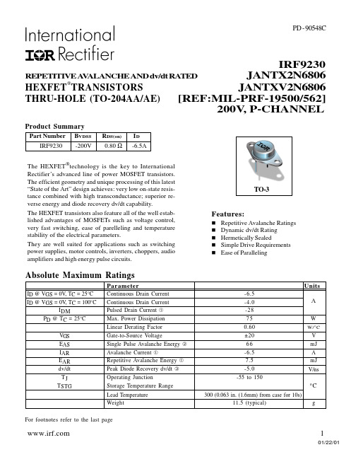
Operating Junction Storage Temperature Range Lead Temperature Weight
TO-3
Features:
n Repetitive Avalanche Ratings n Dynamic dv/dt Rating n Hermetically Sealed n Simple Drive Requirements n Ease of Paralleling
4
Fig 8. Maximum Safe Operating Area
元器件交易网
Fig 9. Maximum Drain Current Vs. Case Temperature
IRF9230
VDS VGS RG
RD D.U.T.
-10V
Pulse Width ≤ 1 µs Duty Factor ≤ 0.1 %
For footnotes refer to the last page
2
Min Typ Max Units
— — 1.67 °C/W — — 30
Test Conditions Soldered to a 2” square copper-clad board
元器件交易网
Units
-6.5
-4.0
A
-28
75
W
0.60
W/°C
±20
V
66
mJ
-6.5
A
7.5
mJ
-5.0
V/ns
-55 to 150 oC
300 (0.063 in. (1.6mm) from case for 10s)
JAN2N3821中文资料
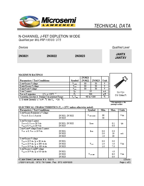
TECHNICAL DATA N-CHANNEL J-FET DEPLETION MODEQualified per MIL-PRF-19500/375Devices Qualified Level2N3821 2N3822 2N3823JANTX JANTXVMAXIMUM RATINGSParameters / Test Conditions Symbol 2N38212N3822 2N3823 UnitGate-Source Voltage V GSR50 30 V Drain-Source Voltage V DS50 30 V Drain-Gate Voltage V DG50 30 V Gate Current I GF 10 mA Power Dissipation T A = +250C (1)P T300 mW Operating Junction & Storage Temperature Range T j, T stg-55 to +200 0C(1) Derate linearly 1.7 mW/C for T A +25 C.package outline ELECTRICAL CHARACTERISTICS (T A = 250C unless otherwise noted)Parameters / Test Conditions Symbol Min. Max. Units Gate-Source Breakdown VoltageV DS = 0, I G = 1.0 µAdc 2N3821, 2N3822 2N3823 V(BR)GSSR5030VdcGate Reverse CurrentV DS = 0, V GS = 30 Vdc 2N3821, 2N3822 V DS = 0, V GS = 20 Vdc 2N3823 I GSSR0.10.5ηAZero-Gate-Voltage Drain CurrentV GS = 0, V DS = 15 Vdc 2N3821 2N3822 2N3823 I DSS0.52.04.02.51020mAGate-Source VoltageV DS = 15 Vdc, I D = 50 µAdc 2N3821V DS = 15 Vdc, I D = 200 µAdc 2N3822 V DS = 15 Vdc, I D = 400 µAdc 2N3823 V GS0.51.01.02.04.07.5VdcGate-Source Cutoff VoltageV DS = 15 Vdc, I D = 0.5 ηAdc 2N38212N3822 2N3823 V GS(off)4.06.08.0Vdc6 Lake Street, Lawrence, MA 018411-800-446-1158 / (978) 794-1666 / Fax: (978) 689-0803120101 Page 1 of 22N3821, 2N3822, 2N3823 JAN SERIESParameters / Test Conditions Symbol Min. Max. Units Small-Signal Common Source, Short-Circuit Forward Transfer AdmittanceV GS = 0, V DS = 15 Vdc, f = 1.0 kHz 2N38212N3822 2N3823 |y fs|1150030003500450065006500µSSmall-Signal Common Source, Short-Circuit Output AdmittanceV GS = 0, V DS = 15 Vdc, f = 1.0 kHz 2N38212N3822 2N3823 |y os|102035µSSmall-Signal, Common-Source Short-Circuit Input CapacitanceV GS = 0, V DS = 15 Vdc, 100 kHz ≤ f ≤ 1.0 MHz C iss 6.0 pF Small-Signal, Common-Source Reverse Transfer CapacitanceV DS = 15 Vdc, V GS = 0, 100 kHz ≤ f ≤ 1.0 MHz2N3821, 2N3822 2N3823C rss3.02.0pFSmall-Signal Common Source, Short-Circuit Forward Transfer AdmittanceV GS = 0, V DS = 15 Vdc, f = 100 MHz 2N3821f = 100 MHz 2N3822 f = 200 MHz 2N3823 |y fs|2150030003200µSSmall-Signal, Common-Source Short-Circuit Input ConductanceV GS = 0, V DS = 15 Vdc, f = 200 MHz 2N3823 (only)g is 800 µS Small-Signal, Common-Source Short-Circuit Output ConductanceV GS = 0, V DS = 15 Vdc, f = 200 MHz 2N3823 (only)g os 200 µS Common Source Spot Noise FigureV GS = 0, V DS = 15 Vdc, R G = 1MΩf = 10 Hz2N3821, 2N3822f = 1.0 kHz 2N3821, 2N3822, 2N3823NF1 5.02.0dBCommon Source Spot Noise FigureV GS = 0, V DS = 15 Vdc, R G = 1kΩf = 105 MHz2N3823 (only)NF22.5dB6 Lake Street, Lawrence, MA 018411-800-446-1158 / (978) 794-1666 / Fax: (978) 689-0803120101 Page 2 of 2。
- 1、下载文档前请自行甄别文档内容的完整性,平台不提供额外的编辑、内容补充、找答案等附加服务。
- 2、"仅部分预览"的文档,不可在线预览部分如存在完整性等问题,可反馈申请退款(可完整预览的文档不适用该条件!)。
- 3、如文档侵犯您的权益,请联系客服反馈,我们会尽快为您处理(人工客服工作时间:9:00-18:30)。
MAXIMUM RATINGS (TA = 25° C unless otherwise noted) 2N5681 Ratings Symbol
Collector-Emitter Voltage Collector-Base Voltage Emitter-Base Voltage Collector Current Base Current Total Power Dissipation @ TA = +250C(1) @ TC = +250C(2) Operating & Storage Temperature Range VCEO VCBO VEBO IC IB PT Top, Tstg Symbol RθJC 100 100 4.0 1.0 0.5 1.0 10 -65 to +200
V(BR)CEO
Vdc µAdc µAdc
IEBCBO
100
nAdc
6 Lake Street, Lawrence, MA 01841 1-800-446-1158 / (978) 794-1666 / Fax: (978) 689-0803
120101 Page 1 of 2
元器件交易网
2N5681, 2N5682 JAN SERIES ELECTRICAL CHARACTERISTICS (con’t)
Characteristics Symbol Min. Max. Unit
ON CHARACTERISTICS (3)
Forward Current Transfer Ratio IC = 250 mAdc, VCE = 2.0 Vdc IC = 500 mAdc, VCE = 2.0 Vdc IC = 1.0 Adc, VCE = 2.0 Vdc Collector-Emitter Saturation Voltage IC = 250 mAdc, IB = 25 mAdc IC = 500 mAdc, IB = 50 mAdc Base-Emitter Saturation Voltage IC = 250 mAdc, IB = 25 mAdc IC = 500 mAdc, IB = 50 mAdc hFE 40 20 5 150
VCE(sat)
0.6 1.0 1.1 1.3
Vdc
VBE(sat)
Vdc
DYNAMIC CHARACTERISTICS
Magnitude of Common Emitter Small-Signal Short Circuit Forward-Current Transfer Ratio IC = 0.1 Adc, VCE = 10 Vdc, f = 10 kHz Small Signal Short Circuit Forward-Current Transfer Ratio IC = 0.2 Adc, VCE = 1.5 Vdc, f = 1.0 kHz Output Capacitance VCB = 20 Vdc, IE = 0, f = 1 MHz
TO-39* (TO-205AD)
*See appendix A for package outline
ELECTRICAL CHARACTERISTICS (TA = 250C unless otherwise noted)
Characteristics Symbol Min. 100 120 1.0 10 Max. Unit
hfe
hfe Cobo
3.0
40 50 pF
SAFE OPERATING AREA
DC Tests TC = +250C, 1 Cycle, t ≥ 0.5 s Test 1 VCE = 2 Vdc, IC = 1.0 Adc Test 2 VCE = 10 Vdc, IC = 1.0 Adc Test 3
OFF CHARACTERISTICS
Collector-Emitter Breakdown Voltage IC = 10 mAdc 2N5681 2N5682 Emitter-Base Cutoff Current VEB = 4.0 Vdc Collector-Emitter Cutoff Current VCE = 70 Vdc 2N5681 VCE = 80 Vdc 2N5682 Collector-Emitter Cutoff Current VBE = 1.5 Vdc VCE = 100 Vdc 2N5681 VCE = 120 Vdc 2N5682 Collector-Baser Cutoff Current VCE = 100 Vdc 2N5681 VCE = 120 Vdc 2N5682
2N5682
120 120 4.0 1.0 0.5 1.0 10 -65 to +200
Units
Vdc Vdc Vdc Adc Adc W W °C Unit 0 C
THERMAL CHARACTERISTICS
Characteristics Thermal Resistance, Junction-to-Case 1) Derate linearly 5.7 mW/0C for TA > +250C 2) Derate linearly 57 mW/0C for TC > +250C Max. 17.5
元器件交易网
TECHNICAL DATA
NPN POWER TRANSISTOR SILICON AMPLIFIER
Qualified per MIL-PRF-19500/583 Devices 2N5681 2N5682 Qualified Level JAN JANTX JANTXV
VCE = 90 Vdc, IC = 50 mAdc
6 Lake Street, Lawrence, MA 01841 1-800-446-1158 / (978) 794-1666 / Fax: (978) 689-0803
120101 Page 2 of 2