Aeroflex通用仪器产品对比说明
Aeroflex_TETRA测试产品简介

TETRA信号分析仪
2310TETRA信号分析仪----该型仪表是被全行业奉 为标准的专用TETRA信号分析仪。可以对终端或基 站发出射频信号作出最为准确和全面的分析测量。
SVA矢量信号分析仪----该型仪表是最新推出的中高 端矢量信号分析仪,可对TETRA及TETRA II信号进 行分析测量。
6)支持话音和数据加密
TETRA 频谱效率
TETRA基本参数
TETRA帧结构示意图
Hyperframe
1 1 1
2 2 2
3 3 3
4 4 4
14 Bits
5 18
56.7 ms 1.02 s
60
61.2 s
Aeroflex TETRA测试产品简介
今日议题
▼ ▼ ▼ ▼
艾法斯公司及其TETRA相关产品概览 TETRA基本技术及其演进 TETRA相关测试产品 总结与答疑
艾法斯公司及其TETRA相关产品概览
艾法斯公司简介
230
461
TETRA测试相关产品
– 全功能综合测试仪 3920
– 专用综合测试仪 2305
– 专用信号分析仪 2310 – 专用协议分析仪 8140 – 通用仪表 SGD + SVA
综合测试仪3920
▼ ▼ ▼ ▼ ▼ ▼
频率范围 100KHz~1GHz / 2.7GHz 输出电平范围 -130dBm~+10dBm 接收灵敏度 <-113dBm 最大直测功率125W 内置频谱仪、示波器、万用表 选件110:TETRA MS测试
▼
▼ ▼
Aeroflex ATS 主要产品分类
PXI3000 介绍

射频测试挑战
• 无线通信的发展促使技术演进步伐加快,要求 测试解决方案不断提高性能和速度,同时保持 全面灵活性。 • 市场需要能够快速跟进不断变化的市场需求, 加快产品上市速度,降低生产成本的灵活测试 系统。 • 测试解决方案必须满足:灵活性,功能性和精 确性的要求
3020 系列各模块频率与带宽对照图
3020系列参数指标对照表
Basic 3020A Frequency Range Frequency Settling Time Level Range < 3 GHz Level Range > 3 GHz Level Settling Time (list mode) Phase Noise (50 MHz) Phase Noise (2 GHz) Phase Noise (5 GHz) NA 250 MHz to 2.7 GHz 3025 76 MHz to 6 GHz 3020C 1 MHz to 3 GHz 3021C 100 kHz to 3 GHz 250 us <20 us below 85 MHz - 120 to + 6 dBm NA - 121 to + 17 dBm - 120 to + 6 dBm - 120 to + 1 dBm < 3 ms below 3 GHz < 4 ms above 4.5 GHz -143 dBc/Hz ( @20 kHz offset ) -115 dBc/Hz ( @20 kHz offset ) NA -108 dBc/Hz (@20 kHz offset) 90 MHz using int /ext digital 25 MHz with vector modulation (opt 1 fitted) 128 Msamples sample rate variable to 200 Ms/s 2 3 PXI Hybrid 2 3 - 120 to + 17 dBm - 120 to + 17 dBm Enhanced 3025C 1 MHz to 6 GHz 3026C 250 us - 120 to + 5 dBm - 120 to 0 dBm < 3 ms below 3 GHz < 4 ms above 4.5 GHz NA -115 dBc/Hz (@20 kHz offset) NA -108 dBc/Hz (@20 kHz offset) 28 MHz 32 Msamples sample rate variable to 66 Ms/s 2 PXI 1
Aeroflex6113测试仪综合技术培训幻灯片PPT

Aeroflex6113测试工程介绍-随机介入信道测 试
随机介入信道
Aeroflex6113测试工程介绍-接收电平和接收品 质测试
接收电平和接收品质测试
此两项测试的目的是要检测BTS对上行RF信号的处理能力以及BTS通 A-bis接口经上行向BSC汇报的能力。而BSC是通过对BTS的这些 报告来分析处理问题的:如是否切换 功率等级调整以及时间提前量 的处理。换言之,BTS对接收到的信号电平进行归类换算为功率等 级和品质等级并向BSC汇报,而BSC根据这些等级汇报进行分析处 理并决定处理方案,判断测试是否通过。
Aeroflex6113仪表测试连接标准-RBS2302
• A-BIS接法: • A-BIS线接于微蜂窝TIM单元的传输接口
• RF馈线接法: • 由于RBS2302只有2个载波,所以RF馈线都接于微蜂窝馈线输出口 •
Aeroflex6113仪表测试连接标准-RBS2308
• A-BIS接法: • A-BIS线接于微蜂窝IXU单
在软件方面,它包含两方面技术:
基站厂家操作维护码,需要各基站厂家提供,这是测试的基本前提;
仪表固有的发射机、接收机的测试功能
Aeroflex6113仪表原理及技术性能
➢ 适用于GS900/1800/1900频段的基站测试,是基站测试领域 的行业测试标准。
➢ 支持GSM,GPRS,EDGE,AMR测试 ➢ 接收机、发射机测试 ➢ 手动测试,自动测试 ➢ 支持主流基站品牌的测试〔 ERICSSON, MOTOROLA,
随机介入信道测试
此项测试是通过雷卡仪器模拟MS,从BTS的RF接收端以一定的电平 值发出一定数量的具有不同时间提前量的RACH申请,再从A-bis接 口上监测BTS对这些信号的响应能力。简单的说这个测试功能是从 时间提前量的角度出发检测BTS对RACH的处理能力。
Airflex 产品选择和程序册:工业紧耦合和断机产品说明书

Airflex®Product selection and program brochureIndustrial Clutch and Brake Products2WCBWCBD/33,400 - 6003,400 - 6003,400 - 7001,200 - 600EDCBby electronic controls. When a system overload isdetected, the TLC automatically disengages.*Speed decreases as torque increases due to increasing inertiaExpanding Clutches and BreaksDrum style products that when pressurized, expandradially outward forcing their friction shoes againstan inner cylindrical drum surface.*Speed decreases as torque increases due to increasing inertiaTLCSinglePneumatic Controls – Quick Release Valves (QRV)Engineered to automatically close uponpressurization and open when a pressure dropoccurs – reducing lag time to exhaust the system.Four valve sizes are available.Pneumatic Controls – RotorsealsAllow passage of pressurized fluids from a stationary inlet to arotating shaft end. Available with single and dual passages.*Speed at Maximum TorqueQRVFlow Rate (ft3/m)Dual Electronic Controls – Slip Detection ControlsAborts the start if excessive slip is detected.It also detects slippage during operation.3almost every industry. To reach the application engineering team, please contact:Email: (best and preferred method) *********************Website for product support:/en/products/dps/clutches-and-brakes/Literature and Reference MaterialFor more information: • Go to PowerSource, , Products, Clutches and Brakes • Online at /en/products/dps/clutches-and-brakes/Airflex quality has been proven with over 80 years of field experience, across multiple markets and countless applications. This warranty serves to provide even further confidence and value in the Airflex brand.4Airflex Clutches and BrakesProduct NomenclatureConstrictingType CB, Type CM, Type VCThese elements are identified by the drum diameter in inches on which they constrict and the width in inches of their friction lining. For instance, a size 26CM475 is designed to constrict on a 26 inch diameter drum and has a friction lining width of 4.75 inches.Airflex® clutches and brakes embody the principles of classic design: superior performance, long life, and high quality. For over 80 years, we’ve been providing superior drivetrain products by continuously adapting and innovating our products to meet industry requirements. With global operations—including manufacturing, sales, and distribution—spanning multiple continents worldwide, our dedicated team can help you select or develop customized solutions for your individual needs.Air-CooledType DBA, Type DBB, Type DBBS, Type DCThese elements’ sizes are indicated by the number of brake/friction discs and the disc diameter in inches. For instance, a size 229DBA has two discs 29 inches in diameter.ExpandingType E, Type EB, Type ERThese elements are identified by the inside drum diameter in inches to which they expand and the width in inches of their friction lining. For instance, a size 16E475 is designed to expand to a 16 inch diameter drum and has a friction lining width of 4.75 inches.Spring AppliedType CS, Type CSA, Type CTEFor these elements, sizes are identified by the outside drum diameter in inches on which the brake worksand the width in inches of their friction lining. For instance, a size 9CSA200 is designed to operate on a 9 inch diameter drum and has a friction lining widthof 2 inches.Water-CooledType WCB2/WCBD, Type WCS, Type WCSBFor these elements, sizes are indicated by the number of friction discs and the disc diameter in inches. For instance, size 224WCB has two friction discs 24 inches in diameter.5Market ApplicationConstricting Expanding Coupling Spring Applied Market Application CB VC CM E EB ER TLC CS CTEOil/Gas/Water Drilling Systems Cat Head Compound Drawworks Offshore Pipe Laying Mooring Systems Power Take Off PumpsRotary TableSand ReelTop DriveMining and Cement ConveyorsCrushersDraglinesGrinding MillsShovelsMarine Anchor Winch/WindlassBow ThrusterDredgesGeneratorMain PropulsionPipe Laying EquipmentPower Take OffPropeller Shaft BreakPumpsCan Making BodymakerCupperPulp and Paper CalendarConvertersConveyorsCouchDryerPressesPulpersReelRewind StandSlittersUnwind StandYankee DryerMetalworking Alligator SheersCar ShreddersCoining PressDraw BenchesExpandersForging PressesHeaders/UpsettersMachine ToolsMulti-SlidePowder Metal PressesPress BrakesRebar ShearRewind StandsRoll FormingRoller LevelerShearsSlittersSpring CoilingStamping, Punching, FormingUnwind StandsWire CageDynamometer AbsorberHolding BrakeEngines Generator SetPower Take OffLogging SkiddersYardersDrum Product 67Drawworks:only mechanical brake needed. The water cooled portionof the brake offers energy absorption (HP) capacity, whilethe spring set function accommodates “fail safe” brakingDragline:exceptional friction life and the capability to quickly makefriction changes. It is supplied with long wearing, organicfriction material and a rugged solid cast, rotating disc thatprovides lower intertia than typical caliper brakes.FHB9Rewind, Unwind Stand:tension or pull on the material. Improper tensioningwhile winding can result in roll dishing or telescoping.It could also cause clutter, affecting the reprocessing 1011© Danfoss | Power Solutions | January 2023AD426647228681en-000201Any information, including, but not limited to information on selection of product, its application or use, product design, weight, dimensions, capacity or any other technical data in product manuals, catalogues descriptions, advertisements, etc. and whether made available in writing, orally, electronically, online or via download, shall be considered informative, and is only binding if and to the extent, explicit reference is made in a quotation or order confirmation. Danfoss cannot accept any responsibility for possible errors in catalogues, brochures, videos and other material. Danfoss reserves the right to alter its products without notice. This also applies to products ordered but not delivered provided that such alterations can be made without changes to form, fit or function of the product. All trademarks in this material are property of Danfoss A/S or Danfoss group companies. Danfoss and the Danfoss logo are trademarks of Danfoss A/S. All rights reserved.Danfoss Power Solutions, Nordborgvej 81, 6430 Nordborg, Denmark, Tel. +45 74 88 22 22, Fax +45 74 65 25 80 ,E-mail:****************。
Aeroflex 2394A 1 kHz 至 13.2 GHz 光谱分析仪说明书

2394AA s p e c t r u m a n a l y z e r w i t h o u t s t a n d i n g p e r f o r m a n c e a n d a u s e r f r i e n d l y v i s u a l i n tMarker TableThe marker system allows up to a maximum of 9 markers to be dis-played on the screen at any one time. A marker table shows the fre-quency and level of each marker selected thus allowing multiple sig-nals to be evaluated simultaneously. In addition to the Normal mark-ers 2394A provides Delta, Peak Search, Peak T rack, 1/Delta, Markerrack, Marker to Center and Marker to Reference capabilities.Measurement LimitsThe Limits facility allows an Upper and/or a Lower Limit to be seton the screen of the 2394A. Should the signal being displayed falloutside either limit a message will appear on the screen showingwhich limit has been exceeded and how many times this hashappened.X dB DownOccupied BandwidthChannel PowerHarmonic Distortion Adjacent Channel PowerS P E C I F I C A T I O NF R E Q U E N C YTuning Range1 kHz to 13.2 GHzRange Band1 kHz to 3 GHz 02.9 GHz to 6.4 GHz 16.3 GHz to 13.2 GHz 2All ranges employ fundamental mixing.Resolution1 HzFrequency Span Width100 Hz/div to 1000 MHz/div in 1, 2, 5 step selections (auto-selected) Zero span and Full span (1 kHz to 13.2 GHz)Manual selection of Start, Stop and SpanSpan Accuracy<±3% of indicated span widthReadout Accuracy± (Span Accuracy + Frequency Standard Accuracy + 50% of RBW) StabilityResidual FM <100 Hz p-p at 1 kHz RBW, 1 kHz VBW,(p-p in 200 ms)Noise Sidebands<-90 dBc/Hz at 10 kHz offset measured at 2.9 GHz-98 dBc/Hz at 100 kHz offset measured at 2.9 GHzF R E Q U E N C Y C O U N T E RResolution1 Hz, 10 Hz, 100 Hz and 1 kHzAccuracy±(Reference frequency error + frequency readout accuracy + counter resolution ±1 count)Sensitivity<-70 dBm from 50 kHz to 13.2 GHzA M P L I T U D EMeasurement Range+30 dBm to -110 dBmDisplayed Average Noise Level (DANL)300 Hz RBW, 10 Hz VBW, 50 Ωtermination-105 dBm @ 50 kHz to 100 kHz***************************************************************Pre-amp On-115 dBm @ 50 kHz to 100 kHz******************************************1 dB Compression Point>-10 dBm, 100 kHz to 13.2 GHz at 0 dB attenuation Displayed Range100 dB in 10 dB/div log scale50 dB in 5 dB/div log scale20 dB in 2 dB/div log scale10 dB in 1 dB/div log scale 10 divisions with linear amplitude scale Amplitude UnitsLog scale mode dBm and dBmV. Linear scale mode V (µV, mV, etc.) or dBV (dBmV only) Quasi Peak mode dBµV, dBmV or dBmDisplay Linearity5 and 10 dB/div, ±0.1 dB/dB, ±1.0 dB over 10 divisions1 and2 dB/div, ±0.5 dB over 10 divisionsLinear, ±10 % of Reference Level over 10 divisionsFrequency Response1 kHz to 5 MHz-3 dB to +1 dB5 MHz to 2.9 GHz ≤±1.0 dB2.9 GHz to 6.4 GHz<±1.5 dB6.4 GHz to 13.2 GHz<±2.2 dBA T T E N U A T O RRange0 dB to 55 dB in 5 dB steps selected manually or automatically coupled to the Reference LevelAccuracy±0.5 dB/step up to ±1.5 dB maximumR E F E R E N C E L E V E LRange-110 dBm to +30 dBm with 1 kHz filter using 1 dB/div scale Accuracy±1.0 dB (50 kHz to 13.2 GHz)Resolution0.1 dB stepsResidual Spurious-85 dBm (input terminated, 0 dB attenuation)Harmonic Distortion-60 dBc (-40 dBm input at 0 dB attenuation)Intermodulation Distortion-70 dBc 100 MHz to 13.2 GHz-65 dBc 1 MHz to 100 MHz (at -30 dBm input, 0 dB input attenuation)Other Spurious-60 dBc (10 MHz to 13.2 GHz at -30 dBm)R E S O L U T I O N B A N D W I D T HSelection-300 Hz, 1 kHz, 3 kHz, 10 kHz, 30 kHz, 100 kHz, 300 kHz, 1 MHz, 3 MHz9 kHz and 120 kHz (Quasi-Peak Detector, Option 4)100 Hz, 30 Hz, 10 Hz (Digital Resolution Bandwidth, Option 5) Accuracy±10% (Digital Resolution Bandwidth, Option 5)±20%For the very latest specifications visit Data Length7 bit or 8 bit selectableStop Bits1 bit or2 bitProtocolNone, Xon-Xoff, RTS-CTS, DTR-DSRE N V I R O N M E N T A LOperating0 to 40°CStorage-20 to +60°CTemperature & HumidityMeets MIL-T-28800E for Type 2, Class 5, non-condensing(85% operating, 90% storage)Vibration/ShockMeets MIL-T-28800E for Type 2, Class 5AltitudeOperational up to 3,000 m (19,842 ft.), non-operational to 12,200 m (40,026 ft).P R O D U C T S A F E T YConforms to EN61010-1 for Class 1 portable equipment and is for use in a pollution degree 2 environment. The instrument is designed to operate from an Installation Category II.E L E C T R O M A G N E T I C C O M P A T A B I L I T YComplies with the limits specified in the following standards:EN 55011: Class A and EN 50082-1G E N E R A L C H A R A C T E R I S T I C SDIMENSIONS350 mm (13.78 in.) W, 185 mm (7.28 in.) H, 395 mm (15.5 in.) D including handleWeight<12 kg/26.5 lbs (without options)Warm-up Time15 minutes for specified accuracyP O W E R R E Q U I R E M E N T SVoltage100 to 240 VAC ± 10%Frequency50 to 60 HzPower Consumption100 W max (without options fitted)H A R D W A R E O P T I O N SH I G H S T A B I L I T Y T I M E B A S E(O P T I O N03)Temperature Stability<±0.2 ppm/°C 0°C to 40°CAgeing Rate<±0.1 ppm/yrQ U A S I-P E A K D E T E C T O R(O P T I O N04)Quasi-Peak detector and EMC filtersRBW9 kHz Band B120 kHz Band C Frequency Range150 kHz to 30 MHz30 MHz to 1 GHz Charge Time (ms) 1 ±20% 1 ±20% Discharge Time (ms)160 ±20%550 ±20%Display Time (ms)160 ±20%100 ±20%D I G I T A L RE S O L U T I O N B A N D W I D T HF I L T E R S(O P T I O N05) Bandwidths100 Hz, 30 Hz, 10 HzBandwidth accuracy±20%Selectivity (-60 dB/-3 dB)<5:1Maximum span1 MHzSweep times for 10 kHz spanRBW100 Hz<0.9 sec30 Hz<3 sec10 Hz<4.5 secDisplayed Average Noise Levels (DANL) between 1 MHz and 13.2 GHz reduces DANL by typically 5 dB from the values in the 300 Hz resolution bandwidth filter.A C/D C P O W E R S U P P L Y(O P T I O N6)DC Voltage12 VDC to 21 VDCExternal Battery14.4 VDC @ 7 AHFor the very latest specifications visit For the very latest specifications visit 。
Aeroflex T1203 产品说明书

OPERATION MANUALT1203DME, ATC, LRA DISCRETE FUNCTIONINTERFACE UNITMANUAL NUMBER:06-1203-01 (Hard Copy)E6-1203-01 (CD)REVISION:0DATE:03/26/2007WARNING: INFORMATION SUBJECT TO EXPORT CONTROL LAWSThis manual may contain information subject to the International Traffic in Arms Regulation (ITAR) or the Export Administration Regulation (EAR) which may not be exported, released, or disclosed to foreign nationals inside or outside of the United States without first obtaining an export license. A violation of the ITAR or EAR may be subject to a penalty of imprisonment and/or fines under 22 U.S.C.2778 of the Arms Export Control Act or section 2410 of the Export Administration Act. Include this notice with any reproduced portion of this document.This document is proprietary to Aeroflex, and is not to be reproduced or otherwisedisseminated without the written consent of Aeroflex.400 New Century Parkway – New Century, Kansas – 66031Telephone: (800) 237-2831 / (913) 764-2452 Fax: (913) 782-5104ELECTROSTATIC DISCHARGE GENERAL WARNINGS FOR ALL EQUIPMENTCAUTION:THIS EQUIPMENT MAY CONTAIN ELECTROSTATIC DISCHARGE (ESD) SENSITIVE COMPONENTS. TO PREVENT ESD SENSITIVE EQUIPMENT FROM POSSIBLEDAMAGE, OBSERVE THE FOLLOWING PRECAUTIONS WHEN HANDLING ANY ESDSENSITIVE COMPONENTS, OR UNITS CONTAINING ESD SENSITIVECOMPONENTS:a. Maintenance or service personnel must be grounded though a conductive wrist strap, or a similargrounding device, using a 1 MΩ series resistor for equipment protection against static discharge, and personal protection against electrical shock.b. All tools must be grounded (including soldering tools) that may come into contact with theequipment. Hand contact will provide sufficient grounding for tools that are not otherwisegrounded, provided the operator is grounded through an acceptable grounding device such as a wrist strap.c. Maintenance or service of the unit must be done at a grounded, ESD workstation.d. Before maintenance or service of the equipment, disconnect all power sources, signal sources,and loads connected to the unit.e. If maintenance or service must be performed with power applied, take precautions againstaccidental disconnection of equipment components. Specifically, do not remove integratedcircuits or printed circuit boards from equipment while the equipment has power applied.f. All ESD sensitive components are shipped in protective tubes or electrically conductive foam.The components should be stored using the original container/package when not being used or tested. If the original storage material is not available, use similar or equivalent protectivestorage material.g. When ESD sensitive components are removed from a unit, the components must be placed on aconductive surface, or in an electrically conductive container.h. When in storage or not being repaired, all printed circuits boards must be kept in electricallyconductive bags, or other electrically conductive containers.i. Do not unnecessarily pick up, hold, or directly carry ESD sensitive devices.Failure to comply with these precautions may cause permanent damage to ESD sensitive devices. This damage can cause devices to fail immediately, or at a later time without apparent cause.Aeroflex Operation ManualREVISION HISTORY BY DRAWING NUMBER MANUAL: T1203 DME, ATC, LRA Discrete Function Interface UnitREVISION: 0 – March 26, 2007REV. REV._LEVEL DRAWING NO. LEVEL NO.DRAWINGTable of Contents 00Section I 00Section II 00Section III 00Section IV 00Section V 00Aeroflex Operation ManualTABLE OF CONTENTSSECTION IGENERAL INFORMATIONParagraph Page1.1 INTRODUCTION.........................................................................................1-1DESCRIPTION.....................................................................1-1 1.2 EQUIPMENTCHARACTERISTICS.............................................................1-1 1.3 TECHNICAL1.4 UNITS & ACCESSORIES SUPPLIED........................................................1-1EQUIPMENT............................................................................1-2 1.5 OPTIONALINFORMATION..........................................................................1-2 1.6 RELATEDSECTION IIINSTALLATION2.1 GENERALINFORMATION.........................................................................2-1 2.2 UNPACKING AND INSPECTING EQUIPMENT.........................................2-1 2.3 EQUIPMENT SETUP..................................................................................2-1SECTION IIIOPERATION3.1 INTRODUCTION.........................................................................................3-1FUNCTIONS.............................................................................3-1 3.2 CONTROLFront Panel.................................................................................3-1-3.2.1 Controls-Rear Panel..................................................................................3-4 3.2.2 ControlsSECTION IVTHEORY OF OPERATION4.1 GENERALCIRCUIT THEORY....................................................................4-1 Amp Board........................................................................................4-1 4.1.1 AudioSECTION VMAINTENANCEINFORMATION................................................................5-1 5.1 MAINTENANCESECTION I - GENERAL INFORMATION1.1 INTRODUCTIONThis manual contains information relative to the physical, mechanical and electrical characteristics of the Aeroflex Model T1203 Discrete Function Interface Unit (DFIU), PN: 01-1203-00.1.2 EQUIPMENT DESCRIPTIONThe T1203 DFIU is designed to operate and test ARINC 700 Series DME - Distance MeasuringEquipment (ARINC 709), ATCRBS - Air Traffic Control Radar Beacon System Transponder (ARINC 718) and LRA - Low Range Altimeter (ARINC 707) line replaceable units. Power control and protection, as well as all necessary discretes and monitoring points are provided. ARINC 429 transmission and reception to and from the LRU's is provided by the companion T1200 Control Display Unit (CDU) via a rear panelinterfaceconnector.Detachable interface cable/breakout boxes are available which connect either the DME, ATC or LRA to the T1203. These units contain any unique requirements for each type LRU. Where applicable, magnetic overlays for each manufacturer's LRU are available which identify the ATE test point matrix.1.3 TECHNICAL CHARACTERISTICS(6.82lbs.Kg)15Weight:(30.86cm)in.12.15Height:(48.26cm)19.00in.Width:in.cm)(22.869.00Depth:27.5VDC@ 2 Amps 115VAC/400Hz @ 2 AmpsRequirements:PowerOperating Temperature: +10 to +45 deg. C1.4 UNITS AND ACCESSORIES SUPPLIEDThe Aeroflex Model T1203 DFIU, P/N 01-1203-00, consists of the main test panel and theaccessories:followingDESCRIPTION JcAir P/NITEMCDE6-1203-01OperationManual1 T1203Cable 55-2406-002 115V/400HzPower1.5 OPTIONAL EQUIPMENTThe following items are available as optional equipment with the T1203 DFIU. They must be orderedseparately.DESCRIPTION P/NITEM55-1203-01Cable1 T1203-01InterfaceDME55-1203-02InterfaceCable2 T1203-02ATCCableInterface55-1203-03LRA3 T1203-034 T1203-04 TRT TSR-718 Interface Cable 55-1203-045 T1203-07 Bendix/King KXP-7510 Interface Cable 55-1203-076 T1203-09 TRT TDM-709 Interface Cable 55-1203-097 T1203-10 TRT ERT-530 Interface Cable 55-1203-10-58-1169-08DME-700OverlayPoint8 Test58-1169-09LRA-700-9 TestPointOverlayTPR-710A58-1169-10Overlay-Point10Test1.6 RELATED INFORMATIONFor information regarding the T1203 Interface Cables, refer to their individual maintenance manuals. For reference purposes, the Aeroflex part numbers for these manuals are as follows:INTERFACE CABLE MANUAL P/NT1203-01 C6-1203-01T1203-02 C6-1203-02T1203-03 C6-1203-03T1203-04 C6-1203-04T1203-07 C6-1203-07T1203-09 C6-1203-09T1203-10 C6-1203-102.1 GENERAL INFORMATIONThis section contains information relating to the unpacking, inspection and setup of the T1203 DFIU and accessories.2.2 UNPACKING AND INSPECTING EQUIPMENTCarefully remove the T1203 DFIU and accessories from the packing box. Make a visual inspection of the unit for evidence of damage incurred during shipment. If a claim for damage is to be made, save theshipping container to substantiate the claim. When all equipment has been unpacked, return the packing material to the container for future use in storing or shipping the equipment.2.3 EQUIPMENT SETUPThe T1203 DFIU may be installed free standing on a workbench table top or mounted in a 19-inchequipment rack using the integral rack mounting ears.Connect 28VDC power to the banana jack/binding posts (J11) at the rear of the T1203.Connect 115VAC/400Hz power to the receptacle (J10) at the rear of the T1203 using the power cord(JPN: 55-2406-00) provided with the test set.*** NOTE ***The power cord provided is left unterminated at one end to accommodate wiring to your own particular 115VAC/400Hz supply. The wires should be connected as follows:BLK Wire - 115VAC/400Hz HotWHT Wire - 115VAC/400Hz NeutralGRN Wire - 115VAC/400Hz GroundConnect a T1200 CDU to the T1200 Interface connector (P401) at the rear of the T1203 using the T1200 DFIU Cable, PN: 55-2401-00, supplied with the T1200.The LRU is connected to the T1203 via the appropriate T1203 Interface Cable. Where applicable, install the appropriate magnetic test point overlay (See section 1.5) to the test point field on the front panel of the Interface Cable.IMPORTANTRefer to the appropriate Component Maintenance Manual (CMM) or test procedure for additional testequipment setup procedures.3.1 INTRODUCTIONThis section contains the basic operating procedure for the T1203 DFIU.3.2 CONTROL FUNCTIONSThe T1203 provides all the necessary signals for testing the ARINC 700 Series DME, ATC and LRAunits. The following is a description of each of the controls provided on the DFIU.NOTESome additional controls may be installed on the LRU Interface Cables.3.2.1 CONTROLS - FRONT PANEL (Fig. 3-1)(1) DFIU POWER ON/OFF Switch (S39) The T1203 power requirements are provided by anexternal 28VDC source connected to the T1203 througha set of banana jack/binding posts (J11) on the rearpanel. The power to the DFIU is turned ON or OFF withswitch.toggleaDPST(2) DFIU POWER Fuse (F2) Provides over-current protection for the T1203 internalcircuitry.(3) DFIU POWER Lamp (DS2) Illuminates when the DFIU 28VDC power is switched onby S39.(4) UUT POWER ON/OFF Switch (S38) The Unit Under Test power requirements are providedby an external 115VAC/ 400Hz source connected to theT1201 through a 3-conductor power receptacle (J10) onthe rear panel. The power to the UUT is turned ON orDPSTswitch.toggleaOFFwith(5) UUT POWER Fuse (F1) Provides over-current protection for the unit under test.(6) UUT POWER Lamp (DS1) Illuminates when the UUT 115VAC/400Hz power iswithS38.onswitched(7) CURRENT MONITOR Jacks (J8 & J9) These test jacks allow the user to calculate the currentdrawn by the UUT by measuring the AC voltage droppedacross a precision 1 ohm resistor (R1) in series with theconnection to the UUT power input (1 volt = 1 amp).(8) LRU Connector (J1) 156-pin DL connector used to connect with the DME,InterfaceLRUCables.ATCandLRA(9) ARINC 429 OUTPUT BUS Jacks Four 1/4" stereo phone jacks allow monitoring of the(J205, J206, J209, J210) ARINC 429 output buses from the UUT.(10) ARINC 429 INPUT BUS Jacks Four 1/4" stereo phone jacks allow monitoring of the(J203, J204, J207, J208) ARINC 429 input buses to the UUT.(11) SDI CODE Switch (S36) Allows changing the SDI input straps to each possible3).-codeSDI(0(12) LRU 115VAC OUTPUT Jacks Allows monitoring of the 115VAC/400Hz Indicator and(J4, J5, J6, J7) Control Panel outputs from the DME.(13) ATC MONITOR Enunciators Indicates the status of the Monitor A and B LampATCTransponder.fromthe(CR1, CR2) outputs(14) DABS CAPABILITY BITS OPEN/GND switches reserved for the DABS Capability(S14-S23) A through K discrete inputs to the ATC Transponder.(15) PILOT ACKNOWLEDGE (PB) OPEN/GND switches reserved for the Pilot(S24, S25) Acknowledgment PB (bit nos. 14 & 15) discrete inputsTransponder.ATCtothe(16) ALTITUDE SELECT Switch (S13) OPEN/GND switch used to control the ALTITUDEATCTransponder.thediscreteSELECTinputto(Parallel = OPEN, Serial = GND)(17) MODE C Select Switches (S35) Four thumb-wheel switches used to provide the GillhamtheTransponder.ATCtocodealtitude(18) MAX AIRSPEED Switch (S34) Not currently provided.(19) ANTENNA AVAILABILITY (S12) OPEN/GND switch used to control the ANTENNAtheATCTransponder.inputtoAVAILABILITYdiscrete=SingleGND)OPEN,(Dual=(20) DABS ADDRESS Switch (S33) Not currently provided.(21) INPUT SELECT Switch (S11) OPEN/GND switch used to control the CONTROL DATAINPUT PORT SELECT discrete input to the ATCTransponder. (PORT B = OPEN, PORT A = GND)(22) AIR/GROUND Switch (S10) OPEN/GND switch used to control the SQUITTERINHIBIT discrete input to the ATC Transponder. (AIR =OPEN, GROUND = GND)(23) FUNCTIONAL TEST Switch (S9) OPEN/GND switch used to control the FUNCTIONALTEST discrete input to the ATC Transponder. (OFF =OPEN, ON= GND)(24) DEFAULT SCAN INHIBIT OPEN/GND switch used to control the DEFAULT SCANSwitch (32) INHIBIT discrete input to the DME. (STBY = OPEN,SCAN = GND)switches used to control the INDICATORSTATUS OPEN/GNDINDICATOR(25)Switches (S28, S29) STATUS #1 and #2 discrete inputs to the DME. (FAULT= OPEN, 1 or 2 = GND)(26) MAINTENANCE RESET Switch (S31) OPEN/GND switch used to control the MAINTENANCERESET discrete input to the DME. (DOWN = OPEN,GND)=RESET(27) AIR/GROUND Switch (S27) OPEN/GND switch used to control the AIR/GROUNDdiscrete input to the DME. (GROUND = OPEN, AIR =GND)(28) DATA SOURCE Switch (S30) OPEN/GND switch used to control the DATA INPUTPORT SELECT discrete input. (PORT B = OPEN,PORT A = GND)(29) FUNCTIONAL TEST Switch (S26) OPEN/GND switch used to control the FUNCTIONALTEST discrete input to the DME. (OFF = OPEN, ON =GND)(30) AUDIO OUTPUT Jacks (J2, J3) Allows monitoring of the audio output signal from theDME.(31) AUDIO LOAD Switch (S37) Allows selecting various loads for the DME audio output.The AMP position connects the audio output to theinternal amplifier and speaker. In the EXT position, nointernal load is applied so that an external load can beOutputAudiojacks.connectedacrossthe(32) VOLUME CONTROL (R2) Controls the volume of the speaker.(33) SPEAKER (LS1) A 45 ohm speaker for reproducing the receiver audiofrom the DME.(34) FUNCTIONAL TEST INHIBIT OPEN/GND switch used to control the Switch (S2)FUNCTIONAL TEST INHIBIT discrete input to the LRA.(OFF = OPEN, ON = GND)(35) FUNCTIONAL TEST Switch OPEN/GND switch used to control the FUNCTIONALTEST discrete input to the LRA. (OFF = OPEN, ON =GND)(36) INDICATOR STATUS Switches OPEN/GND switches used to control the INDICATOR(S3, S4) STATUS #1 and #2 discrete inputs to the LRA. (FAULT= OPEN, 1 or 2 = GND)(37) AFS DATA Switch (S5) Two position toggle switch which allows the operator toconnect the AFS DATA CONTROL pin to either theprogramtheorpinDATAINTERRUPTEDAFSonLRA.pintheAFSprogramCONTINUOUSDATA(38) AIR/GROUND Switch (S6) OPEN/GND switch used to control the AIR/GROUNDdiscrete input to the LRA. (GROUND = OPEN, AIR =GND)(39) ANTENNA DISABLE Switch (S7) Two position toggle switch which allows the user tojumper the ANTENNA MONITOR program pin to thepinontheDISABLEprogramANTENNAMONITORDISABLESHORTED)OPEN,=LRA.(OFF=(40) AID SELECT Switch (S8) Allows connection of either the 40, 57 or 80 Ft. AID(Aircraft Installation Delay) program pin to the AIDLRA.theonpinCOMMON3.2.2 CONTROLS - REAR PANEL (Fig. 3-2)(1) 28VDC Power Input Jacks (J11) A set of banana jack/binding posts used to connect thepowersource.28VDCtoDFIUa(2) 115VAC/400Hz Power Used to connect the DFIU to a 115VAC/ 400Hz powerReceptacle (J10) source via the detachable 3-conductor power cord.(3) REMOTE SELECTOR Switch (S40) This switch has no current function and is notoperational.(4) T1200 INTERFACE Connector (P401) A 37-pin female D connector used to interface the DFIUCDU.T1200atoFig. 3-1: T1203 Controls - Front PanelFig. 3-2: T1203 Controls - Rear PanelSECTION IV - THEORY OF OPERATION4.1 GENERAL CIRCUIT THEORYThe only active circuitry contained in the T1203 is contained on the Audio Amp printed circuit board. The following is a brief description.4.1.1 AUDIO AMP BOARDThe Audio Amp Board, PN 20-5625-00, is mounted to the inside of the front panel. It is used to provide the selectable loads for the receiver's audio output and to provide a variable amplified output to drive the panel mounted speaker.SECTION V - MAINTENANCE5.1 MAINTENANCE INFORMATIONBills of material, assembly drawings, schematics and a test procedure for the Aeroflex Model T1203 are contained in the T1203 Maintenance Manual (P/N 06-1203-00 for hard copy, E6-1203-00 for CD) available separately from Aeroflex.For information regarding the T1203 Interface Cables, refer to their individual maintenance manuals. The part numbers for these manuals are as follows:MANUAL P/NINTERFACE CABLET1203-01 C6-1203-01T1203-02 C6-1203-02T1203-03 C6-1203-03T1203-04 C6-1203-04T1203-07 C6-1203-07T1203-09 C6-1203-09T1203-10 C6-1203-10。
Aeroflex 8140 TETRA Air Analyzer 产品说明书

Suspect Faults in the Message Flow?The T etra MSC application visualizes the signaling messages received over the air interface in a clear and concise way. Thanks to the structured layout, users can easily identify which message is transmitted on what protocol layer. The messages are individually tagged with a time stamp and the relevant RF parameters, such as frame number, frequency offset and signal strength. Signaling messages not conforming to TETRA standard EN 300 392 are marked with a different color. With a click on the marked message, the application displays a detailed error description.A number of filter functions eases fault tracing because the user can reduce the messages displayed to those which are of interest in the case at hand.Figure 2: Invalid messages are clearly marked in the messagesequence chart Analyzing Voice Communication and Voice QualityThe 8140 TETRA AirAnalyzer and its associated PC software can output and store voice data received over the air interface, enabling users to evaluate the voice quality and to observe communications over the network. With the voice decoder function, users can monitor speech on two time slots and record it in Wave sound format for later analysis. The direction and time slot can be selected on a straight forward user interface.Figure 3: Voice playback and storage can be triggered once thedirection and time slots have been selectedFigure 4: The TETRA Scanner application provides an overviewon spectrum occupation, load and traffic Finding TETRA Carrier ProblemsThe TETRA scanner searches for TETRA carriers in a user-defined frequency range. In addition to the available TETRA channels, the broadcast parameters are displayed for each carrier with a main control channel. This feature helps to easily identify network configuration problems. The channels available can be monitored because the usage of time slots for traffic (TCH) is displayed and permanently updated. Associated measurement values, such as received signal strength or frequency error, are shown in a diagram.This tool offers an easy way to check the results of network planning in real life, so that the network can be optimized if necessary. The current network status in regard to quality and quantity can be evaluated, so the tool can be used to find the best possible utilization of resources. With a GPS mouse connected to the computer, the 8140TETRA AirAnalyzer can even be turned into a full featured drive test receiver with real-time storage of the current position.Figure 5: With the 8166 Coverage Test Option and ESRI ArcGISthe 8140 becomes a powerful drive test receiverExtending the Range of Possibilities With Options8165 TETRA QoS AnalyzerThe optional 8165 TETRA QoS Analyzer application provides an easy way to evaluate the quality of service; the results of the QoS parameters are displayed graphically for easier interpretation. In the TETRA AirAnalyzer, quality of service means more than just radio coverage: T o ensure that the TETRA network for safety-critical operations can perform the required service, more data are of importance. Call setup time, number of queued calls and associated wait time, call priorities and cell load are important parameters to describe the network quality. Emergency services have high demands on these parameters for safely performing their tasks.In order to ease the evaluation of the quality of service in a fast and comfortable way, the results are displayed easily readable, either in graphical or tabular format.8160 Static Air Interface Encryption Option, 8161Static/Dynamic Air Interface Encryption OptionIn organizations ensuring public safety and security, voice calls and data transmission over the TETRA network are confidential by nature and therefore protected by air interface encryption. In these types of networks, the functionality of the 8140 TETRA AirAnalyzer is ensured by the 8161 static/dynamic air interface ecnryption option. The encryption algorithm (TEA 1 through 4) and the encryption keys must be provided by the user.8162 DMO OptionO ne of the strengths of the TETRA standard is the possibility to communicate between two radios in Direct Mode O ption (DMO), without the need to be attached to a radio network. With the 8162 DMO option, the TETRA AirAnalyzer also analyzes DMO and DMO gateway signaling messages.8164 TETRA AirAnalyzer Office SoftwareThe application software for the TETRA AirAnalyzer is protected with a USB dongle. In order to be able to use the applications on a second PC for offline analysis of captured data, the 8164 TETRA AirAnalyzer office software can be used with exactly the same functionality and options as the first license. The additional software license comes on a separate USB dongle.Figure 6: Network performance under real-life conditions can be evaluated with the 8165 TETRA QoS Analyzer.SPECIFICATIONSThe published accuracies are determined in accordance with GUM (Guide to the Expression of Uncertainty in Measurement) and EA (European Co-operation for Accreditation) application document EA4/02: “Expressions of the Uncertainty of Measurements in Calibration”.RECEIVERFrequency Range400 MHz version: 360 to 473 MHz800 MHz version: 804 to 931 MHzConnectionTwo N-type socketsInput Impedance50 ΩInput VSWR<1.5 (typ.)Reference Frequency Uncertainty<10-7Max. Input Power0 dBmTypical Sensitivity<–106 dBm dynamic<–115 dBm staticGENERAL DATACasing19” rack-mount model, 3 HUTemperature Range0°C to +50°CVoltage SupplyWide AC input range with power factor correction95 V to 250 VPower Consumption<60 WWeight<15 kg (33 lbs.)Data Connection100 Base-T Ethernet, RJ-45For the very latest specifications visit Part No. 46891/375, Issue 1, 05/10。
Aeroflex S-1403DL MLD Mode S Accessory Unit 产品说明书
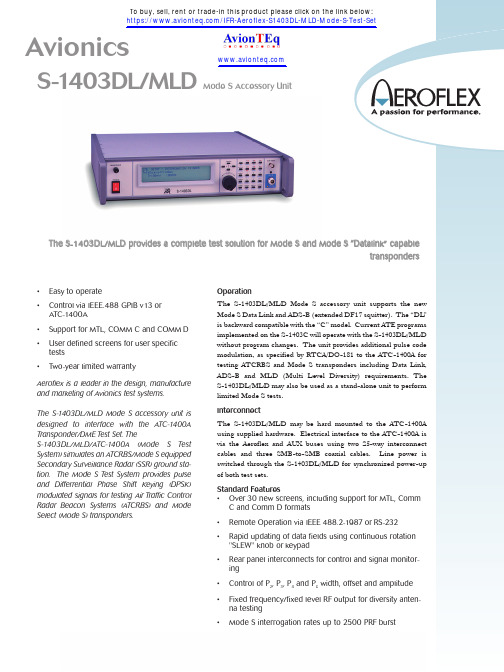
S-1403DL/MLDT h e S-1403D L/M L D p r o v i d e s a c o m p l e t e t e s t s o l u t i o n f o r M o d e S a n d M o d e S“For the very latest specifications visit SEQ0% to 100% in 1% steps. Displays percent of valid replies that are Mode S onlyAnt. ADisplayed on ATC-1400A front panelAnt. B0% to 127% in 1% steps. Displays percent of valid replies that return through antenna BAccuracy +1, -0 countsDecoderDecodes downlink data and generates parity information which is com-pared to the "AP" field to check errorsSquitterIndicates Squitter period from 0 to 9.99 seconds in 10 ms steps Accuracy ±0.5 msAddressMode S address selectable from 1 to 2 to the 24th PowerS E Q U E N C E M E N USequence MenuThe Sequence Menu allows the input of Uplink Formats in a program-mable sequence of up to 16 items. Downlink Formats are read-only. Uplink FormatUF00, UF04, UF05, UFll, UF16, UF20 and UF21 are predefined field locations per Table B-3 of the Operation/Maintenance Manual. Formats "S" and "L" are user defined 56-bit and 112-bit words consist-ing of 5 bits octal formatted data, 27 and 83 bits (S/L) of octal infor-mation data, and 24 bits of octal UUT data.Downlink FormatDFOO, DF04, DF05, DF11, DF16, DF20 and DF21 are predefined field locations per Table B-3 of the Operation/Maintenance Manual. Formats "S" and "L" are three fields of generic data consisting of5 bits of octal formatted data; 27 or 83 bits of octal information data and 24 bits of octal address data.A D D I T I O N A L F U N C T I O N SRF Level"RFLvl" key followed by a number will raise or lower the ATC-1400A RF level by 3.0 dB in 0.1 dB steps.Accuracy ±10%Ant. BUsed to enable or disable the second RF output for diversity testing Frequency1030 MHz accuracy 0.001%RF Level-20 to -83 dBmAccuracy±1 dB relative to the ATC-1400A output at -50 dBm G E N E R A LCalibration Interval1 yearAC Supply100 to 120 VAC, 220 to 240 VAC, 50 Hz to 60 Hz, ≤+10% of the nominal voltage48 W maximum (163 W maximum with ATC-1400A)AC OutputLine output, fused at 3 A and switchedENVIRONMENTALTemperature5° to 40°CRelative Humidity≤80% for temperatures up to 31°C, decreasing linearly to 50% at 40°C (Non condensing)Altitude≤4000 m (13,124 ft)Electromagnetic CompatibilityComplies with the limits in the following standards:EN 55011 Class BEN50082-1SafetyComplies with EN 61010-1:1993 for class 1 portable equipment and is for use in a pollution degree 2 environment. The instrument is designed to operate from an installation category 1 or 2 supply. Dimensions425 mm wide, 467 mm deep, 89 mm high16.8 in. wide, 18.4 in. deep, 3.5 in. highWeight6.75 kg (15 Ibs.)For the very latest specifications visit V E R S I O N S A N D A C C E S S O R I E SWhen ordering please quote the full ordering number information.Ordering NumbersVersions1403MLD-110S-1403DL/MLD Mode S with Level Diversity,110 VAC operation1403MLD-220S-1403DL/MLD Mode S with Level Diversity,220 VAC operationAccessories (Supplied)Line CordAUX Bus Interface CableAeroflex Bus Interface CableOperation Manual3 x RF Coaxial Interface CableLine Cord from ATC-1400A to S-1403DL/MLD All Aeroflex Avionics products delivered with Factory Certificate Of Calibration。
- 1、下载文档前请自行甄别文档内容的完整性,平台不提供额外的编辑、内容补充、找答案等附加服务。
- 2、"仅部分预览"的文档,不可在线预览部分如存在完整性等问题,可反馈申请退款(可完整预览的文档不适用该条件!)。
- 3、如文档侵犯您的权益,请联系客服反馈,我们会尽快为您处理(人工客服工作时间:9:00-18:30)。
2
2030/2031/2032
-安捷伦 MXG模拟信号源N5181A. - 安捷伦MXG ATE 模拟信号源N5161A -安捷伦N9310A 国产模拟信号发生器 - 罗德斯瓦茨SMA100A - 罗德斯瓦茨SMB100A - 罗德斯瓦茨SMC100A -安捷伦 MXG模拟信号源N5181A. - 安捷伦MXG ATE 模拟信号源N5161A -安捷伦N9310A 国产模拟信号发生器 - 罗德斯瓦茨SMA100A - 罗德斯瓦茨SMB100A - 罗德斯瓦茨SMC100A
1
2399C/2394A/2395A
频谱仪部分(数字) 频谱仪部分(数字)
#B 型号 对比仪器 注释
1
3251/3252/3253/3254
-安捷伦ESA系列E440XB -安捷伦CXA系列N9000A -安捷伦EXA系列N9010A -罗德斯瓦茨FSP系列 -安立MS2690A
325x数字频谱分析仪频率范围: 1kHz~3GHz/8GHz/13.2GHz/26.5GHz
2
3281A/3282A/3283A
-安捷伦PSA E444X系列 -安捷伦PXA N9030A系列 -罗德斯瓦茨FSV系列 -罗德斯瓦茨FSQ系列 -罗德斯瓦茨FSU系列 -安立MS2830A
328x数字频谱分析仪频率范围: 3Hz~3GHz/13.2GHz/26.5GHz
*Note: 1. PXI系列通用测试产品:关于PXI总线模块化信号发生器及信号分析仪产品部分请与艾法斯工程师直接联系。
203x信号源频率范围10KHz~1.35/2.7/5.4GHz
204x信号源频率范围10KHz~1.35/2.7/5.4GHz
3
2040/2041/2042
2026A/B信号源频率范围10KHz~2.05/2.51GHz
4
2026A/B
-暂无独立仪表直接竞争
信号源部分(数字) 信号源部分(数字)
#B 型号 对比仪器
Aeroflex通用仪器对比选型说明 通用仪器对比选型说明
Last updated: Aug 23, 2010
通用仪器用户:射频相关器件,模组生产制造,研发单位,电子类产品, 通用仪器用户:射频相关器件,模组生产制造,研发单位,电子类产品,汽车 电子类产品研发/生产,运营商及无线设备维护单位, 电子类产品研发/生产,运营商及无线设备维护单位,各科研院所 信号源部分(模拟) 信号源部分(模拟)
-安捷伦E442/3X ESG系列 -安捷伦MXG数字信号源N5182A -安捷伦MXG ATE数字信号源N5162A -罗德斯瓦茨SMU200A -罗德斯瓦茨SMATE200A -罗德斯瓦茨SMJ100A -罗德斯瓦茨SMBV100A -罗德斯瓦茨SM300 -安立MG3700A
注释
3410系列频率范围250KHz~2/3/4/6GHz
1
3412/3413/3414/3416
2050系列频率范围10kHz~1.35GHz/2.7/5.4GHz
-安捷伦E442/3X ESG系列 -安捷伦MXG数字信号源N5182A -安捷伦MXG ATE数字信号源N5162A -罗德斯瓦茨SMU200A -罗德斯瓦茨SMATE200A -罗德斯瓦茨SMJ100A -罗德斯瓦茨SMBV100A 罗德斯瓦茨SM300
#A 型号 对比仪器
-安捷伦 MXG模拟信号源N5181A. - 安捷伦MXG ATE 模拟信号源N5161A -安捷伦N9310A 国产模拟信号发生器 - 罗德斯瓦茨SMA100A - 罗德斯瓦茨SMB100A - 罗德斯瓦茨SMC100A
注释
2023A/B, 2025信号源频率范围 9KHz~1.2/2.05/2.51GHz
2
2050
频谱分析仪部分(模拟) 频谱分析仪部分( 模拟)
#A 型号 对比仪器
- 安捷伦CSA N1996A -安捷伦ESA模拟配置 -罗德斯瓦茨FS300/FS315 -罗德斯瓦茨FSL模拟型号
注释
2399C频率范围:1KHz~3GHz 2394A频率范围:9KHz~13.2GHz 2395A频率范围:9KHz~26.5GHz