ansys pre mesh quality custom quality1
ansysWorkbench菜单选项中英文对照翻译
ansys Workbench;菜单选项中英文对照1、ANSYS12.1 Workbench界面相关分析系统和组件说明【Analysis Systems】分析系统【Component Systems】组件系统】【CustomSystems】自定义系统【Design Exploration】设计优化分析类型Electric (ANSYS)Explicit Dynamics (ANSYS)Fluid Flow (CFX)Fluid Flow (Fluent)Hamonic Response (ANSYS)Linear Buckling (ANSYS)Magnetostatic (ANSYS)Modal (ANSYS)Random Vibration (ANSYS)Response Spectrum (ANSYS)Shape Optimization (ANSYS)Static Structural (ANSYS)Steady-State Thermal (ANSYS)Thermal-Electric (ANSYS)Transient Structural(ANSYS)Transient Structural(MBD)Transient Thermal(ANSYS)说明ANSYS电场分析ANSYS显式动力学分析CFX流体分析FLUENT流体分析ANSYS 谐响应分析ANSYS线性屈曲ANSYS静磁场分析ANSYS模态分析ANSYS 随机振动分析ANSYS响应谱分析ANSYS形状优化分析ANSYS结构静力分析 ANSYS稳态热分析ANSYS热电耦合分析ANSYS结构瞬态分析MBD多体结构动力分析ANSYS瞬态热分析组件类型AUTODYNBladeGenCFXEngineering DataExplicit Dynamic (LS-DYNA )Finite Element ModelerFLUNETGeometryMechanical APDLMechanical ModelMeshResultsTurboGridVista TF说明AUTODYN非线性显式动力分析涡轮机械叶片设计工具CFX高端流体分析工具工程数据工具LS-DYNA显式动力分析FEM有限元模型工具FLUNET流体分析几何建模工具机械APDL命令机械分析模型网格划分工具结果后处理工具涡轮叶栅通道网格生成工具叶片二维性能评估工具2、主菜单【File】文件操作【V iew】窗口显示【Tools】提供工具【Units】单位制【Help】帮助信息3、基本工具条【New】新建文件【Open】打开文件【Save】保存文件【Save As】另存为文件【Import】导入模型【Compact Mode】紧凑视图模式【Shade Exterior and Edges】轮廓线显示【Wireframe】线框显示【Ruler】显示标尺【Legend】显示图例【Triad】显示坐标图示Expand All:展开结构树【Collapse Environments】折叠结构树【Collapse Models】折叠结构树中的Models项【Named Selections】命名工具条【Unit Conversion】单位转换工具【Messages : Messages】信息窗口【Simulation Wizard】向导[Graphics Annotations】注释【Section Planes】截面信息窗口【Reset Layout] 重新安排界面4、建模【Geometry】几何模型【New Geometry】新建几何模型【Details View】详细信息窗口【Graphics】图形窗口:显示当前模型状态【Extrude】拉伸【Revolve】旋转【Sweep】扫掠【Skin/Loft】蒙皮【Thin/Surface】抽壳:【Thin】创建薄壁实体【Surface】创建简化壳【Face to Remove】删除面:所选面将从体中删除。
ANSYSWorkbenchMesh网格划分(自己总结)

ANSYSWorkbenchMesh网格划分(自己总结)Workbench Mesh网格划分分析步骤网格划分工具平台就是为ANSYS软件的不同物理场和求解器提供相应的网格文件,Workbench中集成了很多网格划分软件/应用程序,有ICEM CFD,TGrid,CFX,GAMBIT,ANSYS Prep/Post等。
网格文件有两类:①有限元分析的结构网格:结构动力学分析,电磁场仿真,显示动力学分析;②计算流体力学分析的网格:用于ANSYS CFX,ANSYS FLUENT,Polyflow;这两类网格的具体要求如下:结构网格:①细化网格来捕捉关心部位的梯度,例如温度、应变能、应力能、位移等;②大部分可划分为四面体网格,但六面体单元仍然是首选;③有些显示有限元求解器需要六面体网格;④结构网格的四面体单元通常是二阶的;CFD网格:①细化网格来捕捉关心的梯度,例如速度、压力、温度等;②于是流体分析,网格的质量和平滑度对结果的精确度至关重要,这导致较大的网格数量,经常数百万的单元;③大部分可划分为四面体网格,但六面体单元仍然是首选,流体分析中,同样的求解精度,六面体节点数少于四面体网格的一半。
④CFD网格的四面体单元通常是一阶的一般而言,针对不同分析类型有不同的网格划分要求:①结构分析:使用高阶单元划分较为粗糙的网格;②CFD:好的,平滑过渡的网格,边界层转化;③显示动力学分析:需要均匀尺寸的网格;物理选项实体单元默认中结点关联中心缺省值Coarse Coarse Medium Coarse 平滑度过渡 Mechanical CFD Electromagnetic Explicit Kept Dropped Kept Dropped Medium Medium Medium Fine Fast Slow Fast Slow 注:上面的几项分别对应Advanced中的Element Midside Nodes,以及Sizeing中的Relevance Center,Smoothing,Transition。
ANSYS计算结果无难事,APDL经典命令让你的模型舞起来
ANSYS计算结果无难事,APDL经典命令让你的模型舞起来1、让你的ANSYS模型'舞'起来ANSYS计算结果的动画可采用ANTIME、ANMODE、ANCNTR、ANHARM等自动生成动画(AVI格式),使结果展示更加生动直观,相信使用ANSYS的都会制作。
然而,几何模型或有限元模型则无动画显示功能,有时为展示模型本身,会从多个角度截取图片。
那么,模型能否也可制作动画呢?答案是肯定的。
利用ANSYS的图形存储命令/SEG可以实现此功能,让你的模型动起来。
具体过程详见命令流中及其注释,动画上传总是失败,自己生成不要观看吧。
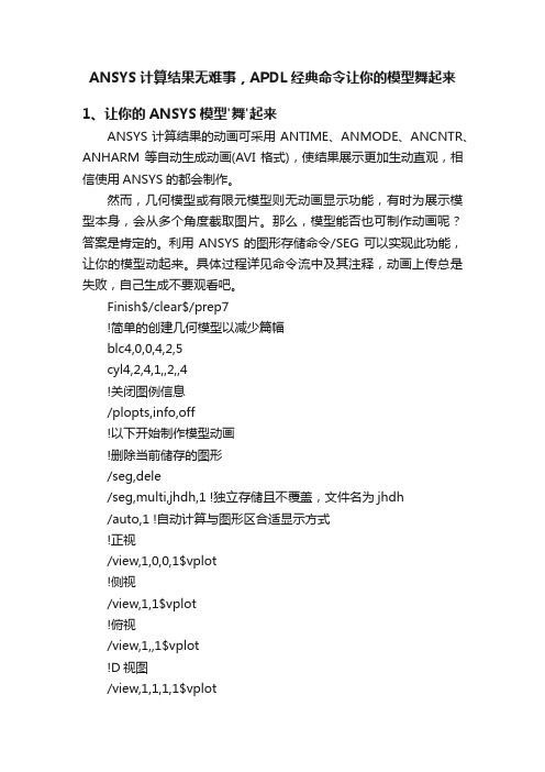
Finish$/clear$/prep7!简单的创建几何模型以减少篇幅blc4,0,0,4,2,5cyl4,2,4,1,,2,,4!关闭图例信息/plopts,info,off!以下开始制作模型动画!删除当前储存的图形/seg,dele/seg,multi,jhdh,1 !独立存储且不覆盖,文件名为jhdh/auto,1 !自动计算与图形区合适显示方式!正视/view,1,0,0,1$vplot!侧视/view,1,1$vplot!俯视/view,1,,1$vplot!D视图/view,1,1,1,1$vplot!循环36次,每次改变10度视角*do,i,1,36$/ang,1,10,ys,1$/replot$*enddo!关闭图形存储操作,保存为jhdh.avi文件/seg,off$/anfile,save,jhdh,avi其实比较简单,一旦进入模型动画制作过程,所有的xPLOT(x=KLAVNE)绘制的图形都将进入动画序列,按显示过程形成一部连续的动画。
2、用一个命令解决ANSYS数据列表分页早年初学ANSYS时,经常用到xLIST(如NLIST、ELIST、KLIST、LLIST、ALIST、VLIST等命令)和PRxSOL(如PRNSOL、PRESOL、PRRSOL、PRETAB、PRPATH)等列表命令,并希望将这些内容保存到TXT文件中,然后再导入EXCEL中处理。
ANSYS workbench网格检查

(学习的目的是增长知识,提高能力,相信一分耕耘一分收获,努力就一定可以获得应有的回报)
Element Quality
基于一个给定单元的体积与边长间的比率。其值处于0和1之间,0为最差,1为最好。
Aspect Ratio
对于三角形,连接一个顶点跟对边的中点成一条线,再连另两边的中点成一条线,最后以这两条线的交点为中点构建两个矩形。之后再由另外两个顶点构建四个矩形。这六个矩形中的最长边跟最短边的比率再除以sqrt(3)。最好的值为1。值越大单元越差。
对四边形而言,通过四个中点构建两个四边形,aspect ratio就是最长边跟最短边的比率。同样最好的值为1。值越大单元越差。
Jacobian Ratio
其值就是最大值跟最小值的比率。1最好。值越大就说明单元越扭曲。如果最大值跟最小值正负号不同,直接赋值-100。
Warping Factor
主要用于检查四边形壳单元,以及实体单元的四边形面。其值基于单元跟其投影间的高差。0说明单元位于一个平面上,值越大说明单元翘曲越厉害。
Parallel Deviation
在一个四边形中,由两条对边的向量的点积,通过acos得到一个角度。取两个角度中的大值。0最好。
Maximum Corner Angle
最大角度。对三角形而言,60度最好,为等边三角形。对四边形而言,90度最好,为矩形。
Skewness
是最基本的网格质量检查项,有两种计算法,Equilateral-Volume-Based Skewness 和 Normalized Equiangular Skewness。其值位于0跟1之间,0最好,1最差。
最新ANSYS系列软件网格质量评定及改进策略汇总

– CFX 求解器是顶点为中心的 ,流体变量单元在顶点存储,求解器单元是双 重网格单元。这意味着网格单元的顶点是求解器单元的中心
A-10
Appendix A: Mesh Quality
CFX网格质量考虑事项
(max,avg)CSKEW=(0.801,0.287) (max,avg)CAR=(8.153,1.298)
网格 2
VzMIN≈-100ft/min VzMAX≈400ft/min
A-9
Appendix A: Mesh Quality
CFX网格质量考虑事项
Training Manual
• CFX求解器对网格质量要求和FLUENT 求解器有点不同,由于两个编码 的求解器结构的不同
• Aspect Ratio:
– 应小于 40, 但取决于流体特性 – 膨胀层可容忍大于 50
• Cell Size Change:
– 应在1与2之间
Training Manual
• 差网格质量可能导致不精 确求解和缓慢收敛 • 一些程序可能要求比建议 值更低的偏斜值
A-7
Appendix A: Mesh Quality
Training Manual
• CFX 求解器有3个重要的网格度量标准,每次运行和更新开始的畸形网格
– 网格正交性 – 纵横比 – 扩展因子
+--------------------------------------------------------------------+
|
Mesh St 0.50-0.80 0.80-0.95 0.95-0.98 0.98-1.00*
ANSYS网格质量检查

A relatively “good” mesh in terms of max skewness, however the average and standard deviation are large
A-20
Appendix A: Mesh Quality
网格质量影响要素
• 膨胀
不适当的:
– – – – 表面网格质量 膨胀表面选择 膨胀选项 膨胀算法 (compression 或 stair-stepping层) – 膨胀参数 – 高级膨胀选项
好的
(OK)
可接受的
(ok)
可疑的
(!)
A-12
Appendix A: Mesh Quality
CFX网格正交性
•正交性度量由以下组成: • ip-face 法向向量, n, 与 • node-to-node 向量, s.
Training Manual
• 正交性椅子 = n· s, >1/3 想要的 • 正交角 = 90º -acos(n· s), >20º想要的 • 这不同于CFD后处理中Max/Min面角? YES!
A-9
Appendix A: Mesh Quality
求解中网格质量的影响
例子
网格 1
(max,avg)CSKEW=(0.912,0.291) (max,avg)CAR=(62.731,7.402)
Training Manual
VzMIN≈-90ft/min VzMAX≈600ft/min
Large cell size change
– 对六面体, 三角形和四边形: 应小于 0.8 – 对四面体: 应小于 0.9
• 差网格质量可能导致不精 确求解和缓慢收敛 • 一些程序可能要求比建议 值更低的偏斜值
ansys中单元质量问题(UnitqualityprobleminANSYS)
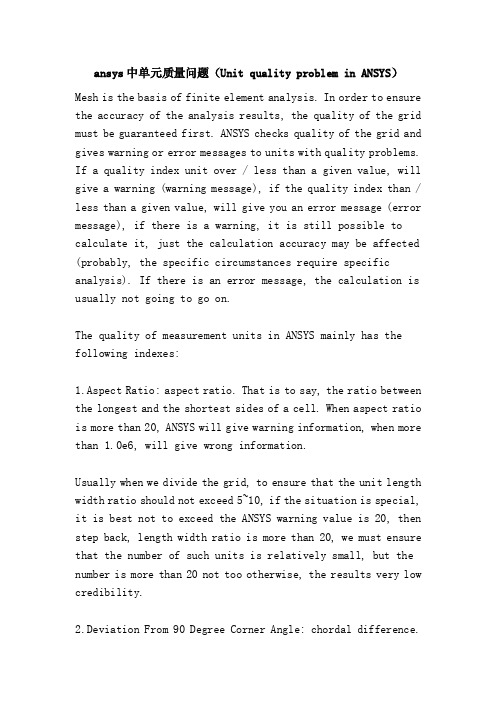
ansys中单元质量问题(Unit quality problem in ANSYS)Mesh is the basis of finite element analysis. In order to ensure the accuracy of the analysis results, the quality of the grid must be guaranteed first. ANSYS checks quality of the grid and gives warning or error messages to units with quality problems. If a quality index unit over / less than a given value, will give a warning (warning message), if the quality index than / less than a given value, will give you an error message (error message), if there is a warning, it is still possible to calculate it, just the calculation accuracy may be affected (probably, the specific circumstances require specific analysis). If there is an error message, the calculation is usually not going to go on.The quality of measurement units in ANSYS mainly has the following indexes:1.Aspect Ratio: aspect ratio. That is to say, the ratio between the longest and the shortest sides of a cell. When aspect ratio is more than 20, ANSYS will give warning information, when more than 1.0e6, will give wrong information.Usually when we divide the grid, to ensure that the unit length width ratio should not exceed 5~10, if the situation is special, it is best not to exceed the ANSYS warning value is 20, then step back, length width ratio is more than 20, we must ensure that the number of such units is relatively small, but the number is more than 20 not too otherwise, the results very low credibility.2.Deviation From 90 Degree Corner Angle: chordal difference.This is for the face element. When there is a chamfer in the structure, the number of mesh layers at the chamfer is higher, and the higher the coincidence degree between the element and the geometry is, at this time,Chord error index is better. On the contrary, the less the number of chamfering layers, the farther the unit deviates from the geometric deviation, the worse the chord difference. As for how ANSYS mathematically defines string difference, there is no way to know. This indicator we usually pay little attention to.3.Deviation From Parallel opposite edges in degrees: quadrilateral opposite side deviation angle. This is only for quadrilateral. Describe the angle between two opposite sides. When the edges are parallel, it is the best case. This index will not focus on him.4.Maximum Corner Angle in Degrees: in the largest unit.For triangular elements, warning information over 165 degrees will be given, and more than 179.9 degrees will give false information.For quadrilateral elements without intermediate nodes, warning information is given over 155 degrees, and error information is given over 179.9 degrees.For quadrilateral elements with intermediate nodes, warning information over 165 degrees will be given, and more than 179.9 degrees will give error information.Jacoby coefficient of 5. Jacobi Ratio.The Jacobi coefficient of ANSYS seems to be different from that of other software, and ANSYS has the limitation of Jacobi coefficient as follows:H-Method element:Warning limit: 30Error limit: 1000P-Method element:Warning limit:30.Error limit:40.The warping coefficient of 6.warping factor:, which is used to describe the warping degree of quadrilateral elements.ANSYS's mathematical definition of warping coefficient is also different from other software.The strange thing is that..,In ANSYS, the warning index and error index used to determine the warping coefficient not only depend on the geometry of the unit, but also on the unit type, the solution of the control parameters, and the unit option. For example, for a shell63 unit,you switch on a large deformation switch and turn off a ON/OFF (NLGEOM), warning indicators and error indicators are different. Whether the KeyOpt (1) of shell63 is equal to 1 will also affect the warning index and error index, as follows:QUAD ELEMENT OR FACE WARPING FACTORSHELL43, SHELL143, SHELL163, SHELL181WARNING TOLERANCE (51) = 1ERROR TOLERANCE (52) = 5INFIN47, INTER115, SHELL131, SHELL57, SHELL157,SHELL63 WITH NLGEOM OFF AND KYOPT1 NOT = 1WARNING TOLERANCE (53) = 0.1000000ERROR TOLERANCE (54) = 1SHELL41, OR SHELL63 WITH KYOPT1=1WARNING TOLERANCE (55) = 0.2000000E-01ERROR TOLERANCE (56) = 0.2000000SHELL28WARNING TOLERANCE (57) = 0.1000000ERROR TOLERANCE (58) = 1SHELL63 WITH NLGEOM ON AND KYOPT1 NOT = 1Warning tolerance (59) = 0.1000000e-04Error tolerance (60) = 0.1000000e-013D solid element faceWarning tolerance (67) = 0.2000000Error tolerance (68) = 0.4000000从上面列出的内容中, 我们可以看到, 有几种情况下shell63的error指标值是非常低的, 也就是说, 单元的翘曲系数很容易超标而报错, 这就要求我们在选择单元类型的时候要注意了.今天在做一个壳 - 壳接触非线性分析的计算的时候, 偶然间发现这个问题的.我用hypermesh划分的网格, 网格质量还可以, 在abaqus里面计算了一遍, 我想把模型再用 ansys算一遍.网格没有任何变化, 单元类型选择的是shell63.但是导入到ansys中求解的时候, 很多单元都因为单元的翘曲系数 (warping factor) 超过错误极限而报错, 计算没法进行.可是单元的质量明明很好啊? 让人一头雾水.折腾了半天, 才弄明白: ansys的翘曲系数的警告极限和错误极限跟单元类型, 求解控制参数, 单元的keyopt选项设置都有关系的.我们大部分情况下都是在用shell63进行线性分析, nlgeom开关是没有打开的, 在这种情况下, 翘曲系数的错误极限值比较大, 不会轻易超标.This is just my analysis of nonlinear contact analysis, and open the NLGEOM switch, according to the above list can be seen, in this case, the warping coefficient shell63 of the unit if more than 0.1000000E-01 will Baocuo, shape is a bit more complicated, the warping coefficients of error limits it is easy to exceed the standard.Solution: change unit type, change shell63 to shell181. From the list above, it can be seen that the warpage error limit and the warning limit of shell181 are not affected by the solution control parameters and the KEYOPT option of the unit.Another solution that might eliminate the warpage factor is: instead of changing the unit type, but setting the Keyopt (1) =1 of the shell63 unit.Because above said easy to exceed the standard, are in the Keyopt (1) is not equal to 1 when appear, if set Keyopt (1) =1, may eliminate warpage coefficient exceeds standard. But when Keyopt (1) =1, the shell63 unit has only the in-plane stiffness (Membrane stiffness only), and that's not what I want, so I'm too lazy to verify it.。
ANSYSWorkbench使用中99%的时候都会用到的操作
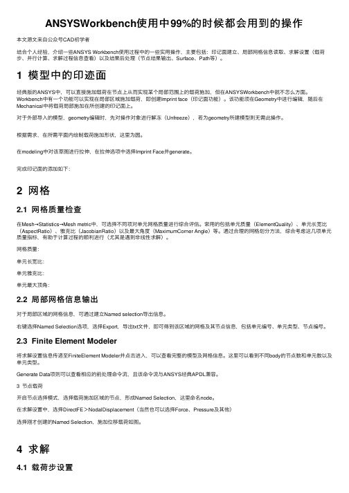
ANSYSWorkbench使⽤中99%的时候都会⽤到的操作本⽂源⽂来⾃公众号CAD初学者结合个⼈经验,介绍⼀些ANSYS Workbench使⽤过程中的⼀些实⽤操作,主要包括:印记⾯建⽴、局部⽹格信息读取、求解设置(载荷步、并⾏计算、求解过程信息查看)以及结果后处理(节点结果输出、Surface、Path等)。
1 模型中的印迹⾯经典版的ANSYS中,可以直接施加载荷在节点上从⽽实现某个局部范围上的载荷施加,但在ANSYSWorkbench中就不怎么⽅⾯。
Workbench中有⼀个功能可以实现在局部区域施加载荷,即创建Imprint face(印记⾯功能)。
该功能须在Geometry中进⾏编辑,随后在Mechanical中将载荷局部施加在所创建的印记⾯上。
对于外部导⼊的模型,geometry编辑时,先对操作对象进⾏解冻(Unfreeze),若为geometry所建模型则⽆需此操作。
根据需求,在所需平⾯内绘制载荷施加形状,这⾥为圆。
在modeling中对该草图进⾏拉伸,在拉伸选项中选择Imprint Face并generate。
完成印记⾯的添加如下:2 ⽹格2.1 ⽹格质量检查在Mesh→Statistics→Mesh metric中,可选择不同项对单元⽹格质量进⾏综合评估。
常⽤的包括单元质量(ElementQuality)、单元长宽⽐(AspectRatio)、雅克⽐(JacobianRatio)以及最⼤⾓度(MaximumCorner Angle)等。
通过合理的⽹格划分⽅法,综合考虑这⼏项单元质量指标,有助于计算过程的顺利进⾏(尤其是遇到⾮线性求解)。
⽹格质量:单元长宽⽐:单元雅克⽐:单元最⼤顶⾓:2.2 局部⽹格信息输出对于局部区域的⽹格信息,可通过建⽴Named selection导出信息。
右键选择Named Selection选项,选择Export,导出txt⽂件,即可得到该区域的⽹格及其节点信息,包括单元编号、单元类型、节点编号。