t2.5.p1
建筑外窗抗风压性能分级及检测方法

建筑外窗抗风压性能分级及检测方法中华人民共和国国家标准建筑外窗抗风压性能分级及检测方法GB/T 7106—2002 1 范围本标准规定了建筑外窗气密性能分级及检验方法。
本标准适用于建筑外窗含落地窗的抗风压性能分级及检测方法。
检测对象只限于窗试件本身不涉及窗与围护结构之间的连接部位。
2 引用标准下列标准所包含的条文通过在本标准中引用而构成为本标准的条文。
本标准出版时所示版本均为有效。
所有标准都会被修订使用本标准的各方应探讨使用权下列标准最新版本的可能性。
GB/ T5823—1986 建筑门窗术语 GBJ 50009—2001 建筑结构荷载规范 3 定义本标准除采用GB/T 5823之外还采用下列定义 31外窗 external window 有一个面朝向室外的窗。
32抗风压性能 wind resistance performance 关闭着的外窗在风压作用下不发生损坏和功能障碍的能力。
33面法线位移 frontal displacement 在窗面上某点所测得的法线方向上的线位移量。
34杆件的面法线挠度 frontal deflection of framemember 杆件在窗面法线方向上最大线位移量和两端线位移量平均值的差值。
35杆件的相对面法线挠度 relative frontal deflection of frame member 窗试件的杆件的面法线挠度和该杆件两端测点间距离的比值。
36压力差 pressure difference 外窗室内外表面所受到的空气压力的差值。
当室外表面空气压力大于室内表面空气压力时压力差为正值反之为负值。
4 分级 41分级指标采用定级检测压力差为分级指标。
分级指标值P3列于表1。
42 P3值与工程的风荷载标准值相对比应大于或等于Wk。
工程的风荷载标准值Wk的确定方法见GBJ 50009。
表1 建筑外窗抗风压性能分级表1 2 3 4 5 6 7 8 ×.×a 分级指标值 P3 1.0?P3 1.5 1.5?P3 2.0 2.0?P32.5 KPa 分级代号2.5?P33.0 3.0?P3 3.5 3.5?P34.0 4.0?P3 4.5 4.5?P35.0 P3?5.0 a表中×.×表示用?5.0KPa的具体值取代分级代号。
DrayTek Vigor2962 Series 2.5G Security VPN Router

Vigor2962 Series2.5G Security VPN RouterQuick Start GuideVersion:1.5Firmware Version: V4.3.2.4(For future update, please visit DrayTek web site)Date: July 7, 2023Intellectual Property Rights (IPR) InformationCopyrights © All rights reserved. This publication contains information that is protected by copyright. No part may be reproduced, transmitted, transcribed, stored ina retrieval system, or translated into any language without written permissionfrom the copyright holders.Trademarks The following trademarks are used in this document:●Microsoft is a registered trademark of Microsoft Corp.●Windows, Windows 8, 10, 11 and Explorer are trademarks of MicrosoftCorp.●Apple and Mac OS are registered trademarks of Apple Inc.●Other products may be trademarks or registered trademarks of theirrespective manufacturers.Safety Instructions and ApprovalSafety Instructions ●Read the installation guide thoroughly before you set up the router.●The router is a complicated electronic unit that may be repaired only beauthorized and qualified personnel. Do not try to open or repair therouter yourself.●Do not place the router in a damp or humid place, e.g. a bathroom.●Do not stack the routers.●The router should be used in a sheltered area, within a temperaturerange of +5 to +40 Celsius.●Do not expose the router to direct sunlight or other heat sources. Thehousing and electronic components may be damaged by direct sunlight or heat sources.●Do not deploy the cable for LAN connection outdoor to prevent electronicshock hazards.●Do not power off the device when saving configurations or firmwareupgrades. It may damage the data in a flash. Please disconnect theInternet connection on the device before powering it off when a TR-069/ ACS server manages the device.●Keep the package out of reach of children.●When you want to dispose of the router, please follow local regulations onconservation of the environment.Warranty We warrant to the original end user (purchaser) that the router will be free from any defects in workmanship or materials for a period of two (2) yearsfrom the date of purchase from the dealer. Please keep your purchase receiptin a safe place as it serves as proof of date of purchase. During the warrantyperiod, and upon proof of purchase, should the product have indications offailure due to faulty workmanship and/or materials, we will, at our discretion,repair or replace the defective products or components, without charge foreither parts or labor, to whatever extent we deem necessary tore-store theproduct to proper operating condition. Any replacement will consist of a newor re-manufactured functionally equivalent product of equal value, and willbe offered solely at our discretion. This warranty will not apply if the productis modified, misused, tampered with, damaged by an act of God, or subjectedto abnormal working conditions. The warranty does not cover the bundled orlicensed software of other vendors. Defects which do not significantly affectthe usability of the product will not be covered by the warranty. We reservethe right to revise the manual and online documentation and to make changesfrom time to time in the contents hereof without obligation to notify anyperson of such revision or changes.EU Declaration of ConformityWe DrayTek Corp. , office at No.26, Fushing Rd., Hukou, Hsinchu Industrial Park, Hsinchu 303, Taiwan, declare under our sole responsibility that the product●Product name: 2.5G Security VPN Router●Model number: Vigor2962, Vigor2962P●Manufacturer: DrayTek Corp.●Address: No.26, Fushing Rd., Hukou, Hsinchu Industrial Park, Hsinchu 303, Taiwanis in conformity with the relevant Union harmonisation legislation:EMC Directive 2014/30/EU, Low Voltage Directive 2014/35/EU and RoHS 2011/65/EU with reference to the following standardsStandard Version / Issue dateEN 550322015+AC:2016 class AEN 61000-3-32013+A1:2019EN 550352017EN 62368-12014+A11:2017EN IEC 63000:2018 2018Hsinchu9th September, 2020Calvin Ma / President (place) (date) (Legal Signature)Declaration of ConformityWe DrayTek Corp. , office at No.26, Fushing Rd., Hukou, Hsinchu Industrial Park, Hsinchu 303, Taiwan, declare under our sole responsibility that the product●Product name: 2.5G Security VPN Router●Model number: Vigor2962, Vigor2962P●Manufacturer: DrayTek Corp.●Address: No.26, Fushing Rd., Hukou, Hsinchu Industrial Park, Hsinchu 303, Taiwan.●Importer: CMS Distribution Ltd: Bohola Road, Kiltimagh, Co Mayo, Irelandis in conformity with the relevant UK Statutory Instruments:The Electromagnetic Compatibility Regulations 2016 (SI 2016 No.1091), The Electrical Equipment (Safety) Regulations 2016 (SI 2016 No.1101), and The Restriction of the Use of Certain Hazardous Substances in Electrical and Electronic Equipment Regulations 2012 (SI 2012 No. 3032) with reference to the following standards:Standard Version / Issue dateEN 550322015+A1:2016 class AEN 61000-3-32013+A1:2019EN 550352017EN 62368-12014/A11:2017EN IEC 63000:2018 2018Hsinchu 2nd August, 2021Calvin Ma / President (place) (date) (Legal Signature)Regulatory InformationFederal Communication Commission Interference StatementThis equipment has been tested and found to comply with the limits for a Class A digital device, pursuant to Part 15 of the FCC Rules. These limits are designed to provide reasonable protection against harmful interference in a residential installation. This equipment generates, uses and can radiate radio frequency energy and, if not installed and used in accordance with the instructions, may cause harmful interference to radio communications. However, there is no guarantee that interference will not occur in a particular installation. If this equipment does cause harmfulinterference to radio or television reception, which can be determined by turning the equipment off and on, the user is encouraged to try to correct the interference by one of the following measures:● Reorient or relocate the receiving antenna.● Increase the separation between the equipment and receiver.● Connect the equipment into an outlet on a circuit different from that to which the receiver is connected.●Consult the dealer or an experienced radio/TV technician for help.This device complies with Part 15 of the FCC Rules. Operation is subject to the following two conditions:(1) This device may not cause harmful interference, and(2) This device may accept any interference received, including interference that may cause undesired operation.More update, please visit .Company nameABP International Inc.Address 13988 Diplomat Drive Suite 180 Dallas TX 75234 ZIP Code 75234 E-mail*******************USA Local RepresentativeContact PersonMr. Henry N CastilloTel. (972)831-1600 140T a b l e o f C o n t e n t s1. Package Content (1)2. Panel Explanation (2)2.1 LED for Vigor2962 and Vigor2962P (2)2.2 Connectors for Vigor2962 and Vigor2962P (3)3. Hardware Installation (4)3.1 Connecting Device (4)3.2 Wall-Mounted and Rack-Mounted Installation (5)4. Software Configuration (6)4.1 Quick Start Wizard for Network Connection (6)5. Customer Service (13)Be a Registered Owner (13)Firmware & Tools Updates (13)1. P a c k a g e C o n t e n tTake a look at the package content. If there is anything missed or damaged, please contact DrayTek or dealer immediately.Vigor routerQuick Start GuideRJ-45 Cable (Ethernet)Standard bracketsThe type of the power cord depends on the country that the router will beinstalled.UK-type Power CordEU-type Power CordUSA/Taiwan-type Power CordAU/NZ-type Power CordNoteInput Rated for Vigor2962: 100~240V, 50/60Hz, 0.7A Input Rated for Vigor2962P: 100~240V, 50/60Hz, 1.5A2. P a n e l E x p l a n a t i o n2.1 L E D f o r V i g o r 2962 a n d V i g o r 2962PLEDStatusExplanationBlinking The router is powered on and running normally. ACTOff The router is powered off.On The fiber connection is established. Blinking The data is transmitting.SFPOff No fiber connection is established or the system is hanged.On The USB device is installed and ready. USB Off No USB device is installed.MSGOn / Off / Blinking MSG means this LED is user-defined. It will be on / off / blinking according to the rule defined on WUI. On Power sourcing equipment for PoE is enabled. PoE (for 2962P) Off Power sourcing equipment for PoE is disabled.On A PoE equipment is connected to port P1, P4, P5 or P6. P1, P4, P5, P6 (for 2962P)Off No PoE equipment connected. On The Ethernet link is established. OffNo Ethernet link is established. LeftBlinking The data is transmitting.On The Ethernet link is established with 1/2.5Gbps. P1RightOff The Ethernet link is established with less than 1Gbps. OnThe Ethernet link is established on corresponding port. OffNo Ethernet link is established. LeftBlinking The data is transmitting.OnThe Ethernet link is established on corresponding port with 1Gbps.P2 (Right) ~P6RightOffThe Ethernet link is established on corresponding port with less than 1Gbps.2.2 C o n n e c t o r s f o r V i g o r 2962 a n d V i g o r 2962PInterfaceDescriptionResetThe Factory Reset button is used to restore the default settings. Turn on the router (ACT LED is blinking). Press the hole and keep for more than 5 seconds. When you see the ACT LED begins to blink rapidly than usual, release the button. Then the router will restart with the factory default configuration.P1 Connector for local network devices (LAN) or a modem for accessing Internet (WAN). P2 (Left) Connector for SFP module with the rate of 1G bps. P2 (Right)~P4 Connectors for remote network devices or local network devices (WAN/LAN) with the rate of 1G/100M/10M bps. Or connector for a modem for accessing Internet (WAN). P5~P6 Connectors for local network devices (LAN) with the rate of 1G/100M/10M bps. USB1~2Connector for the USB device.Connector for a power cord. ON/OFF - Power switch.Note 1P1 to P4 port can be configurable as WAN / LAN interface. At least, up to two of them can be set as the WAN port at one time.For Vigor2962P, P1, P4, P5 and P6 also can be connected by PoE equipments.Note 2The PoE Power budget is up to 60W.3.H a r d w a r e I n s t a l l a t i o nThis section will guide you to install the router through hardware connection and configure the router’s settings through web browser.3.1C o n n e c t i n g D e v i c eBefore starting to configure the router, you have to connect your devicescorrectly.1.Connect a modem to any WAN port of Vigor2962 with Ethernet cable (RJ-45)to access Internet.2.Connect the other end of the cable (RJ-45) to the Ethernet port on yourcomputer (that device also can connect to other computers to form a smallarea network). The LAN LED for that port on the front panel will light up.3.Connect the power cord to Vigor2962’s power port on the rear panel, andthe other side into a wall outlet.4.Power on the device by pressing down the power switch on the rear panel.The PWR LED should be ON.5.The system starts to initiate. After completing the system test, the ACT LEDwill light up and start blinking.Below shows an outline of the hardware installation for your reference.3.2 W a l l -M o u n t e d a n d R a c k -M o u n t e d I n s t a l l a t i o nThe Vigor2962 Series can be mounted on the shelf or on the wall by usingstandard brackets shown below.W a l l -M o u n t e d1. Choose a flat surface (on thewall) which is suitable for placing the router. Make the screw holes on the short side of the bracket aim at the screw holes on the router. Next,fasten both the bracket and the router with two screws; and fasten both the wall and the bracket with another twoscrews. Refer to the following figure. 2. Then, continue to fasten thescrews on the other side of the router and the wall with other screws. 3. When you finished aboutprocedure, the router has beenmounted on the wall firmly.R a c k -M o u n t e d1. Fasten the rack mount kit onboth sides of the Vigor router using specific screws. 2. Then, install the Vigor router(with rack mount kit) on the 19-inch chassis by using otherfour screws.4. S o f t w a r e C o n f i g u r a t i o nTo access Internet, please finish basic configuration after completing the hardware installation.4.1 Q u i c k S t a r t W i z a r d f o r N e t w o r k C o n n e c t i o nThe Quick Start Wizard is designed for you to easily set up your router for Internet access. You can directly access the Quick Start Wizard via Web User Interface. Make sure your PC connects to the router correctly.NoteYou may either simply set up your computer to get IP dynamically from the router or set up the IP address of the computer to be the same subnet as the default IP address of Vigor router192.168.1.1. For the detailed information, please refer to - Trouble Shooting of the user’s guide.Open a web browser on your PC and type http://192.168.1.1. A pop-up window will open to ask for username and password. Please enter “admin/admin” as the Username/Password and click Login.NoteIf you fail to access to the web configuration, please go to “Trouble Shooting” on User’s Guide for detecting and solving your problem.Now, the Main Screen will pop up. Click Wizards>>Quick Start Wizard.Note The home page will change slightly in accordance with therouter you have.If your router can be under an environment with high speed NAT, the configuration provide here can help you to deploy and use the router quickly. The first screen of Quick Start Wizard is entering login password. After typing the password, please click Next.On the next page as shown below, please select the WAN interface that you use. Then click Next for next step.You have to select the appropriate Internet access type (PPPoE, Static IP or DHCP) according to the information from your ISP.Here we take PPPoE and DHCP modes for WAN connection as examples.F o r P P P o E C o n n e c t i o n1.Choose WAN1 as WAN Interface and click the Next button; you will get thefollowing page.2.Select PPPoE and click Next to get the following page.3.Enter the Username/Password provided by your ISP. Then click Next forviewing the summary of such connection.4.Click Finish. A page of Quick Start Wizard Setup OK will appear.Then,the system status of this protocol will be shown.5.Now, you can enjoy surfing on the Internet.F o r D H C P C o n n e c t i o n1.Choose WAN1 as WAN Interface and click the Next button; you will get thefollowing page.2.Select DHCP and click Next to get the following page.3.Enter the hostname and / or MAC address provided by your ISP. Then clickNext for viewing summary of such connection.4.Click Finish. A page of Quick Start Wizard Setup OK will appear.Then,the system status of this protocol will be shown.5.Now, you can enjoy surfing on the Internet.5.C u s t o m e r S e r v i c eIf the router cannot work correctly after trying many efforts, please contact your dealer for further help right away. For any questions, please feel free to send ***************************.B e a R e g i s t e r e d O w n e rWeb registration is preferred. You can register your Vigor router viahttps://.F i r m w a r e&T o o l s U p d a t e sDue to the continuous evolution of DrayTek technology, all routers will beregularly upgraded. Please consult the DrayTek web site for more information on newest firmware, tools and documents.https://GPL Notice This DrayTek product uses software partially or completely licensedunder the terms of the GNU GENERAL PUBLIC LICENSE. The author ofthe software does not provide any warranty. A Limited Warranty isoffered on DrayTek products. This Limited Warranty does not coverany software applications or programs.To download source codes please visit:GNU GENERAL PUBLIC LICENSE:https:///licenses/gpl-2.0Version 2, June 1991For any question, please feel free to contact DrayTek technical*************************************************.。
物化热力学第二定律习题解答

热力学第二定律习题解答1.已知每克汽油燃烧时可放热 46.86 kJ 。
(1) 若用汽油作以水蒸气为工作物质的蒸汽机的燃料时,该机的高温热源为 378 K ,冷凝器即低温热源为 303 K ;(2) 若用汽油直接在内燃机内燃烧,高温热源温度可达到 2273 K ,废气即低温热源亦 为 303 K ; 试分别计算两种热机的最大效率是多少?每克汽油燃烧时所能做出的最大功为多少?T 2 T 1378 303(1)210.20T 2378W Qg48.86 0.20 k J 9.37 kJT 2 T 12273 303(2)210.87T 22273W Qg 48.86 0.87 k J 40.7 kJ652.在 300 K 时, 2 mol 的 N 2 (假设为理想气体)从 106 Pa 定温可逆膨胀到 105Pa ,试计算其 S 。
解38.3 J K53.10 g H 2 (假设为理想气体 )在 300 K,5 105 Pa时,在保持温度为 300 K 及恒定外压为66106Pa 下进行压缩,终态压力为 106Pa ( 需注意此过程为不可逆过程 ) 。
试求算此过程 的 S ,并与实际过程的热温商进行比较。
解 定温过程:108.314ln 5 160 J K -1 28.8J K 2 106Q W p 外 V 2 V 1p 2 V 2 V 1nRT 1 p21.247 104 Jp1Q1.247 104 J 300 K 41.6 J K TS nRln2 8.314 lnp 2106105JK-1S nRlnp 1p2所以 S QT4.在 293 K 时,将一方形容器用隔板从正中间分开,然后将 1 mol N 2和 1 mol He 分别 放在容器的两边, 当将中间隔板抽去以后, 两种气体自动混合。
在此过程中系统的温度 不变,与环境没有热交换,试求此混合过程的S ,并与实际过程的热温商进行比较。
E_380采煤机图纸整理_贵州织金大雁煤矿_35CJ10-01-JX1电气系统接线图 Model (1)
XT1[插头(6P)]
181 179 182 180 183
XT5[插头(3P)]
196 197 L2 2 198 L3 3 201 200
XT6[插头(7P)]
Lc.1 Lb.1 La.1 XT.43 XT.42 XT.45 XT.44 199 L1' 3 98 Ti3 4 97 COM 5 100 Ti4 6 99 COM 7 184 1
XT.22 XT.25 XT.26 XT.27 XT.28 XT.29 XT.30 XT.31 XT.17 123 1 2 3 133 4 138 124 1 2 125 1 2 5 134 126 1 2 6 127 1 2 7 128 1 2 8 129 1 2 9 130 1 2 10 131 1 2 11 135 XT.18 向左 向右 升速 减速 牵停 运停
L3' L2' 2 1
SRDI
3 113 113 4 114 114 5 115 115 1 ST1 88 2 ST2 89 3 FQ 90 4 RE 87 5 ViN 91 6 GD 86
ADC
7 8 92 9 93 10 11 12 1 2 112 117 EOB1 EOB2 111 93a 94 95 116
描 描
图 校
旧底图总号 底图总号 签 日 字 期
35CJ10/01-JX1
QS (隔离开关) XD (穿墙端子)
连接 连接 线号 XD0 XD0.1 XD0.2 XD0.3 XD1 W1.1 W1.2 W1.3 XD1.1 XD1.2 XD1.3 XD2 W2.1 W2.2 W2.3 XD2.1 XD2.2 XD2.3 347 29 348 349 28 XD3.1 T2.2 XD3.2 XD3.3 T2.1 连接 线号 电抗器L 线号 2 196 连接 XT5.1(L1) 344 345 346 QS.4 QS.5 QS.6 XT11 136 7 8 XD0.3 143 3 6 线号 141 142 143 连接 QS.1 QS.2 QS.3 XD0.2 142 2 5 XD0.1 141 1 4 线号 线号 连接 344 350 190 345 351 191 346 352 192 137 XD1.1 XD3.1 T1.1 XD1.2 XD3.2 T1.2 XD1.3 XD3.3 T1.3 XT12 端子号 1 2 3 4 5 6 7 8 9 10 11 12 13 14 15 16 17 18 XD3 W3.1 W3.2 W3.3 350 XD3.1 XD3.2 XD3.3 347 351 348 352 349 QS.4 XD2.1 QS.5 XD2.2 QS.6 XD2.3 连接 线号 QS.4 QS.5 QS.6 190 1 1140V/380V 7 139 XT.21 8 140 XT.24 4 5 6 19 20 线号 连接 193 La.1 194 Lb.1 195 Lc.1 21 22 23 24 T1.4/XT6.3(L1') 193/199 1 La T1.5/XT6.2(L2') 194/200 1 Lb T1.6/XT6.1(L3') 195/201 1 Lc W0.1 W0.2 W0.3
传质分离过程课后习题答案
第一章绪论略第二章习题1. 计算在和下苯(1)-甲苯(2)-对二甲苯(3)三元系,当x 1 = 、x 2 =、x 3 =时的K 值。
汽相为理想气体,液相为非理想溶液。
并与完全理想系的 K 值比较。
已知三个二元系的wilson 方程参数(单位: J/mol ):λ12-λ11=-; λ12-λ22= λ23-λ22=; λ23-λ33=- λ13-λ11=; λ13-λ33=-在T = K 时液相摩尔体积(m 3/kmol )为: =×10 -3 ;=×10 -3 ;=×10 -3安托尼公式为(p s :Pa ; T :K ): !苯:1n =();甲苯:1n=();对 -二甲苯:1n = ();解:由Wilson 方程得:Λ12=l l V V 12exp[-(λ12-λ11)/RT]=331091.1001055.177⨯⨯×exp[-/×]=Λ21= Λ13= Λ31= Λ23= Λ32= lnγ1=1-ln(Λ12X 2+Λ13X 3)-[3322311313233221122131321211X X X X X X X X X X X X +Λ+ΛΛ+Λ++ΛA +Λ+Λ+]%=γ1=同理,γ2=; γ3= lnP 1S = P 1S = lnP 2S = P 2S = lnP 3S = P 3S =作为理想气体实际溶液,K 1=P P S11γ=, K 2=, K 3= 若完全为理想系,K 1=P P S1= K 2= K 3=-2. 在361K 和下,甲烷和正丁烷二元系呈汽液平衡,汽相含甲烷%( mol ),与其平衡的液相含甲烷%。
用R -K 方程计算和Ki 值。
解:a 11=115.2242748.0c c p T R ⨯= • dm 6 • • mol -2 a 22=225.2242748.0c c p T R ⨯= MPa •dm 6••mol -2 b 1=11208664.0c c p T R ⨯= dm 3mol -1 b 2=225.2242748.0c c p T R ⨯= dm 3mol -1其中T c1=, P c1=T c2=, P c2= 均为查表所得。
共模滤波器

形状和尺寸(单位:mm)Shape and Dimensions (Unit: mm)品名电感值 [mH]MIN电感偏差 [mH]MAX 直流电阻 [Ω]MAX 额定电流 [A]MAX 1R1A272F20(Y) 2.7 0.135 0.225 1.1 1R0A392F20(Y) 3.9 0.195 0.335 1.0 0R8A682F20(Y) 6.8 0.340 0.530 0.8 0R8A822F20(Y) 8.2 0.410 0.700 0.8 0R7A103F20(Y) 10.0 0.500 0.750 0.7 0R6A123F20(Y) 12.0 0.600 0.970 0.6 0R5A183F20(Y) 18.0 0.900 1.300 0.5 0R3A333F20(Y) 33.0 1.650 2.500 0.3 0R2A563F20(Y) 56.0 2.800 4.600 0.2 0R2A683F20(Y)68.03.400 6.170 0.2形状和尺寸(单位:mm)Shape and Dimensions (Unit:mm)z Rated voltage: AC250Vz Test voltage: 2000VAC, one minute between linesz Insulation resistance: at 500VDC, more than 100MΩ (between lines) z Temperature range: -25℃~T℃ (T=105-temp, rise) 品名 电感值 [mH]MIN电感偏差 [mH]MAX 直流电阻 [Ω]MAX 额定电流 [A]MAX 2R7A152F24(Y) 1.5 0.075 0.055 2.7 2R0A272F24(Y) 2.7 0.135 0.090 2.0 1R6A392F24(Y) 3.9 0.195 0.130 1.6 1R5A472F24(Y) 4.7 0.235 0.160 1.5 1R2A682F24(Y) 6.8 0.340 0.255 1.2 1R1A822F24(Y) 8.2 0.410 0.275 1.1 0R9A123F24(Y) 12.0 0.600 0.350 0.9 0R8A183F24(Y) 18.0 0.900 0.550 0.8 0R7A223F24(Y) 22.0 1.10 0.680 0.7 0R5A333F24(Y)33.01.651.1500.5LF-20 LF-20Y LF-24 LF-24Y MAX 22.7MAX 22MAX 17 MAX 22 M A X 23M A X 17.5(4)(3.5)(10) 4 0.8 (13)(13)4 0.8(17)MAX 19 MAX 26 MAX 25MAX 25M A X 30.5M A X 21(4)(4)(10)4 0.8 (13) (15)4 0.8(21)形状和尺寸(单位:mm)Shape and Dimensions (Unit:mm)品名电感值 [mH]MIN电感偏差 [mH]MAX 直流电阻 [Ω]MAX 额定电流 [A]MAX 3R5A152F28(Y) 1.5 0.075 0.045 3.5 2R7A272F28(Y) 2.7 0.135 0.080 2.7 2R2A472F28(Y) 4.7 0.235 0.110 2.2 2R0A562F28(Y) 5.6 0.280 0.140 2.0 1R7A822F28(Y) 8.2 0.410 0.230 1.7 1R6A103F28(Y) 10.0 0.500 0.250 1.6 1R3A153F28(Y) 15.0 0.750 0.350 1.3 1R2A183F28(Y) 18.0 0.900 0.410 1.2 0R9A273F28(Y) 27.0 1.350 0.650 0.9 0R8A393F28(Y)39.0 1.950 0.865 0.8形状和尺寸(单位:mm)Shape and Dimensions (Unit:mm)z Rated voltage: AC250Vz Test voltage: 2000VAC, one minute between linesz Insulation resistance: at 500VDC, more than 100MΩ (between lines) 品名电感值 [mH]MIN电感偏差 [mH]MAX 直流电阻 [Ω]MAX 额定电流 [A]MAX 4R0A332F35(Y) 3.3 0.165 0.052 4.0 3R5A472F35(Y) 4.7 0.235 0.075 3.5 3R2A682F35(Y) 6.8 0.340 0.093 3.2 3R0A822F35(Y) 8.2 0.410 0.100 3.0 2R5A103F35(Y) 10.0 0.500 0.127 2.5 2R1A153F35(Y) 15.0 0.750 0.180 2.1 1R9A183F35(Y) 18.0 0.900 0.226 1.9 1R8A223F35(Y) 22.0 1.100 0.286 1.8 1R4A333F35(Y) 33.0 1.650 0.418 1.4 1R2A393F35(Y)39.0 1.950 0.468 1.2LF-28 LF-28YLF-35 LF-35YMAX 22 MAX 30MAX 30MAX 30M A X 36M A X 23.5(4)(4)(10) 4 0.8(13)(20)4 0.8(24)MAX 26 MAX 37MAX 37MAX 37M A X 44M A X 29(4)(4)(15) 4 0.8 (21)(25)4 0.8 (30)形状和尺寸(单位:mm)Shape and Dimensions (Unit:mm)品名电感值 [mH]MIN电感偏差 [mH]MAX 直流电阻 [Ω]MAX 额定电流 [A]MAX 0.80A801U9(Y) 0.8 0.040 0.34 0.80 0.80A102U9(Y) 1.0 0.050 0.50 0.80 0.60A152U9(Y) 1.5 0.075 0.52 0.60 0.54A202U9(Y) 2.0 0.100 1.00 0.54 0.42A302U9(Y) 3.0 0.150 1.50 0.42 0.32A502U9(Y) 5.0 0.250 2.50 0.32 0.25A802U9(Y) 8.0 0.400 4.00 0.25 0.23A103U9(Y) 10.0 0.500 4.50 0.23 0.20A153U9(Y) 15.0 0.750 5.50 0.20 0.20A203U9(Y) 20.0 1.000 7.50 0.20形状和尺寸(单位:mm)Shape and Dimensions (Unit:mm)品名电感值 [mH]MIN电感偏差 [mH]MAX 直流电阻 [Ω]MAX 额定电流 [A]MAX 2.0A601U10(Y) 0.6 0.030 0.069 2.0 1.5A102U10(Y) 1.0 0.050 0.120 1.5 1.2A202U10(Y) 2.0 0.100 0.225 1.2 1.0A302U10(Y) 3.0 0.150 0.370 1.0 0.9A502U10(Y) 5.0 0.250 0.480 0.9 0.7A802U10(Y) 8.0 0.400 0.760 0.7 0.4A123U10(Y) 12.0 0.600 1.300 0.4z Rated voltage: AC250Vz Test voltage: 2000VAC, one minute between linesz Insulation resistance: at 500VDC, more than 100MΩ (between lines) z Temperature range: -25℃~T℃ (T=105-temp, rise) UU-9 UU-9Y MAX 17 MAX 11MAX 15.0MAX 17M A X 16M A X 12(4.5)(4.5)(8)4 0.6(7)(7)4 0.6(8)UU-10.5 UU-10.5Y MAX 16.5MAX 18.5 MAX 18.5MAX 17.5M A X 22M A X 17.5(4)(4)(10)4 0.64(13)(10)4 0.64(13)UU-16品名电感值 [mH]MIN电感偏差 [mH]MAX 直流电阻 [Ω]MAX 额定电流 [A]MAX 2.0A102U16 1.0 0.050 0.078 2.0 2.0A202U16 2.0 0.100 0.100 2.0 1.5A302U16 3.0 0.150 0.170 1.5 1.5A352U16 3.5 0.175 0.183 1.5 1.4A502U16 5.0 0.250 0.200 1.4 1.1A802U16 8.0 0.400 0.372 1.1 1.0A103U16 10.0 0.500 0.480 1.0 0.9A123U16 12.0 0.600 0.550 0.9 0.8A183U1618.00.900 0.832 0.8形状和尺寸(单位:mm)Shape and Dimensions (Unit:mm)品名 电感值[mH]±30%以内电感偏差 [mH]MAX 直流电阻 [Ω]±20%以内额定电流 [A]MAX DRB18-02A102 1.0 0.050 0.024 2.0 DRB18-02A202 2.0 0.100 0.031 2.0 DRB18-02A302 3.0 0.150 0.041 2.0 DRB18-02A502 5.0 0.250 0.049 2.0 DRB18-03A102 1.0 0.050 0.014 3.0 DRB18-03A202 2.0 0.100 0.020 3.0 DRB18-03A302 3.0 0.150 0.024 3.0 DRB18-05A102 1.0 0.050 0.010 5.0 DRC18-02A102 1.0 0.050 0.024 2.0 DRC18-02A202 2.0 0.100 0.031 2.0 DRC18-02A302 3.0 0.150 0.041 2.0 DRC18-02A502 5.0 0.250 0.049 2.0 DRC18-03A102 1.0 0.050 0.014 3.0 DRC18-03A202 2.0 0.100 0.020 3.0 DRC18-03A302 3.0 0.150 0.024 3.0 DRC18-05A1021.0 0.050 0.010 5.0z Rated voltage: AC250Vz Test voltage: 2000VAC, one minute between linesz Insulation resistance: at 500VDC, more than 100MΩ (between lines) MAX 19.5 MAX 23.54 0.8 (10) (13)M A X 28(4) MAX 25MAX 20P1P2M A X 27(5)M A X 25MAX 20 (18)(17)(8) 品名P1 P2 DRB18-02A10214 15 DRB18-02A20214 15 DRB18-02A30214 15 DRB18-02A50214 15 DRB18-03A10210 16 DRB18-03A20210 16 DRB18-03A30210 16 DRB18-05A10210 16DRB18 DRC18品名 电感值 [mH]MIN电感偏差 [mH]MAX 直流电阻 [Ω]±20%以内额定电流 [A]MAX DRB25-05A202 2.0 0.100 0.0190 5.0 DRB25-10A102 1.0 0.050 0.0082 10.0 DRB25-15A601 0.6 0.030 0.0043 15.0 DRB25-3.5A802 8.0 0.400 0.0510 3.5 DRB25-05A502 5.0 0.250 0.0280 5.0 DRB25-08A352 3.5 0.175 0.0170 8.0 DRC25-05A202 2.0 0.100 0.0190 5.0 DRC25-10A102 1.0 0.050 0.0082 10.0 DRC25-15A601 0.6 0.030 0.0043 15.0 DRC25-3.5A802 8.0 0.400 0.0510 3.5 DRC25-05A502 5.0 0.250 0.0280 5.0 DRC25-08A3523.5 0.1750.01708.0形状和尺寸(单位:mm)Shape and Dimensions (Unit:mm)z Rated voltage: AC250Vz Test voltage: 2000VAC, one minute between linesz Insulation resistance: at 500VDC, more than 100MΩ (between lines) 品名 电感值 [mH]MIN电感偏差 [mH]MAX 直流电阻 [Ω]MAX 额定电流 [A]MAXDRB31-20A701 0.7 0.035 0.005 20 DRB31-15A701 0.7 0.035 0.008 15 DRB31-15A142 1.4 0.070 0.010 15 DRB31-15A172 1.7 0.085 0.012 15 DRB31-15A202 2.0 0.100 0.014 15 DRB31-10A252 2.5 0.125 0.016 10 DRC31-20A701 0.7 0.035 0.005 20 DRC31-15A701 0.7 0.035 0.008 15 DRC31-15A142 1.4 0.070 0.010 15 DRC31-15A172 1.7 0.085 0.012 15 DRC31-15A202 2.0 0.100 0.014 15 DRC31-10A2522.50.1250.016 10DRB25 DRC25DRB31 DRC31(30) MAX 41M A X 29(17)(5)M A X 43MAX 25 (P2)(5)MAX 36 (P1) M A X 34(P1)(P 2)MAX 23M A X 35(8)品名 P1P2DRB(C)25-05A2021217DRB(C)25-10A1021816DRB(C)25-15A6011816DRB(C)25-3.5A8021217DRB(C)25-05A5021217DRB(C)25-08A3521816形状和尺寸(单位:mm)Shape and Dimensions (Unit:mm)TC品名 电感值 [mH]MIN直流电阻 [mΩ] MAX额定电流 [A]MAX外观尺寸 [mm]MAX TC-8S-30 26 50 2 17*9 TC-8S-40 46 60 2 17*9 TC-8S-50 72 80 2 17*9 TC-8D-30 45 60 2 17*12 TC-8D-40 80 80 2 17*12 TC-8D-50 125 100 2 17*12 TC-10-30 40 40 3 22*12 TC-10-40 75 50 3 22*12 TC-10-50 115 60 3 22*12 TC-12-30 35 30 5 26*13 TC-12-40 64 30 5 26*13 TC-12-50 100 40 5 26*13 TC-13-30 51 23 6 30*17 TC-13-40 92 30 6 30*18 TC-13-50 143 36 6 31*18 TC-16-30 60 21 8 34*19 TC-16-40 108 27 8 35*19 TC-16-50168 318 35*21z Rated voltage: AC250Vz Temperature range: -25℃~T℃ (T=105-temp, rise) zThermal class: E (120℃)※ 可以按照客户要求的电感和额定电流定制产品Custom-mode coils with different inductance and rated current available on request.形状和尺寸(单位:mm)Shape and Dimensions (Unit: mm)注)实物外观和规格书图纸会有细微的差别。
模具标准件编码规则
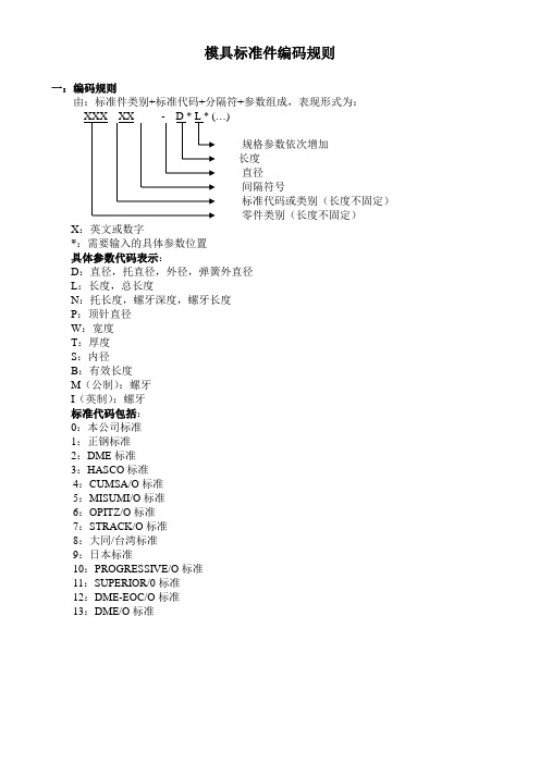
模具标准件编码规则一:编码规则由:标准件类别+标准代码+分隔符+参数组成,表现形式为:)规格参数依次增加长度直径间隔符号标准代码或类别(长度不固定)零件类别(长度不固定)X:英文或数字*:需要输入的具体参数位置具体参数代码表示:D:直径,托直径,外径,弹簧外直径L:长度,总长度N:托长度,螺牙深度,螺牙长度P:顶针直径W:宽度T:厚度S:内径B:有效长度M(公制):螺牙I(英制):螺牙标准代码包括:0:本公司标准1:正钢标准2:DME标准3:HASCO标准4:CUMSA/O标准5:MISUMI/O标准6:OPITZ/O标准7:STRACK/O标准8:大同/台湾标准9:日本标准10:PROGRESSIVE/O标准11:SUPERIOR/0标准12:DME-EOC/O标准13:DME/O标准二:标准件具体编码形式1.单节顶针EP X - DX LX总长度,L表示总长度,X表示具体数据直径,D表示直径,X表示直径数字间隔符号标准代码用数字表示(0、1、2、3、4)分类码,单节顶针用EP表示编码示例:定购正钢顶针直径5.0,长度为100编码:EP2-D5L1002.双节顶针ES X - PX DX NX LX总长度,L表示总长度,X表示具体数据托长度,N表示托,X表示具体数据托直径,D表示托直径,X表示具体数据顶针直径,P表示顶针直径,X表示具体数据间隔符号标准代码用数字表示(0、1、2、3、4)分类码编码示例:定购正钢双节顶针直径1,托直径 2.5,托长度50,总长度为100 编码:ES2-P1D2.5N50L1003.扁顶针ER X - WX TX DX NX LX总长度,L表示总长度,X表示具体数据托长度,N表示托,X表示具体数据托直径,D表示托直径,X表示具体数据顶针直径,T表示厚度,X表示具体数据宽度,W表示宽度,X表示具体数据间隔符号编码示例:定购正钢扁顶针宽度2.0,厚度0.7,托直径3.0托长度50,总长度为100编码:ER2-W2T0.7D3N50L1004.单节司筒CP X - SX DX LX BX有效长度,B表示有效长度,X表示具体数据总长度,L表示总长度,X表示具体数据外径,D表示外径,X表示具体数据内径,S表示内径,X表示具体数据间隔符号标准代码用数字表示(0、1、2、3、4)分类码编码示例:定购正钢单节套筒内径1.5,外径2.3,有效长度10,总长度100编码:CP2-S1.5D2.3L100B105.双节司筒CS X - SX PX DX NX LX BX内径有效长度,B表示内径有效长度,X表示数据总长度,L表示总长度,X表示具体数据托长度,N表示托,X表示具体数据托直径,D表示托直径,X表示具体数据司筒外径,P表示司筒外径,X表示具体数据司筒内径,S表示司筒内径,X表示具体数据间隔符号标准代码用数字表示(0、1、2、3、4)分类码编码示例:定购正钢双节套筒内径1.5,外径2.3,托直径2.8,托长度50,总长度100,有效长度10编码:CS2-S1.5P2.3D2.8N50L100B106.尼龙开闭器PL X - DX M(I)X螺牙,M表示公制螺牙,英制螺牙用I表示,X表示数据直径,D表示直径,X表示直径数字间隔符号标准代码用数字表示(0、1、2、3、4)分类码编码示例:定购正钢尼龙开闭器直径5.0,螺牙10编码:PL2-D5M107.O型密封圈OR X - SX TX厚度,T表示厚度(线径),X表示具体数据内径,S表示内径,X表示直径数字间隔符号标准代码用数字表示(0、1、2、3、4)分类码编码示例:定购正钢密封圈内径10,厚度为2.58止水栓WA X - DX LX长度,L表示长度,X表示具体数据直径,D表示直径,X表示直径数字间隔符号标准代码用数字表示(0、1、2、3、4)分类码编码示例:定购正钢喉塞直径5.0,长度为10编码:BP2-D5L109.止水螺丝WB X - SX NX LX MX螺牙,M表示公制螺牙,英制螺牙用I表示,X表示数据长度,L表示长度,X表示具体数据N表示螺牙深度,X表示具体数据直径,S表示内径,X表示直径数字间隔符号标准代码用数字表示(0、1、2、3、4)分类码10.唧嘴SB X - DX TX LX A(B)区分码,以A和B来区分唧嘴的两个种类总长度,L表示总长度,X表示具体数据厚度,T表示厚度,X表示具体数据直径,D表示直径,X表示直径数字间隔符号标准代码用数字表示(0、1、2、3、4)分类码编码示例:定购正钢浇口杯直径15,厚度20,长度为80编码:SB2-D15T20L8011.法兰LR X - DX TX LX总长度,L表示总长度,X表示具体数据厚度,T表示厚度,X表示具体数据直径,D表示直径,X表示直径数字间隔符号标准代码用数字表示(0、1、2、3、4)分类码编码示例:定购正钢浇口杯直径15,厚度20,长度为80编码:LR2-D15T20L8012.垃圾钉ST X - DX TX厚度,T表示厚度,X表示具体数据直径,D表示直径,X表示直径数字间隔符号标准代码用数字表示(0、1、2、3、4)分类码编码示例:定购正钢垃圾钉直径15,厚度为10编码:ST2-D15T1013.垃圾钉垫片SE X - DX TX厚度,T表示厚度,X表示具体数据直径,D表示直径,X表示直径数字间隔符号标准代码用数字表示(0、1、2、3、4)分类码14.小拉杆螺杆PA X - DX LX NX螺牙深度,X表示数据螺杆长度(不含杯头),X表示数据直径,D表示直径,X表示直径数字间隔符号标准代码用数字表示(0、1、2、3、4)分类码编码示例:定购正钢小拉杆螺杆直径15,长度为100,螺牙深度为20编码:PA2-D15L100N2015.小拉杆PB X - DX LX NX螺牙长度,N表示螺牙长度,X表示具体数据拉杆长度,L表示拉杆长度,X表示具体数据直径,D表示直径,X表示直径数字间隔符号标准代码用数字表示(0、1、2、3、4)分类码编码示例:定购正钢小拉杆直径15,拉杆长度为60,螺牙长度为40编码:PB2-D15L60N4016.行程开关PP X - WX LX长度,L表示长度,X表示具体数据宽度,W表示宽度,X表示直径数字间隔符号标准代码用数字表示(0、1、2、3、4)分类码编码示例:定购正钢行程开关宽度15,长度为20编码:PP2-W15L2017.模具所用所有螺丝PT XX - M(I)X LX螺丝的长度螺丝的直径,M为公制,I表示英制间隔符号型号代码分类码**:螺丝类别编码示例:定购平头螺丝直径为6,长度为15编码:PT-D6L1518.模具所用所有弹簧SP X - DX LX弹簧的长度弹簧的外直径间隔符号颜色代码分类码B Y R G A Z编码示例:定购正钢黄色弹簧直径30,长度为50编码:SPY-D30L5019.扣机(机械式自动开闭器)SL X - XX规格型号(2\2T\3\3T\4\4T),每个型号有对应参数间隔符号标准代码用数字表示(0、1、2、3、4)分类码编码示例:正钢2T型号开闭器SL1-2T20.边锁规格型号,每个型号有对应参数(AX、PLXX)间隔符号标准代码用数字表示(0、1、2、3、4)分类码编码示例:规格为16号的边锁 BS1-A1621.组合章规格型号(6\8\10\12)3表示三组合章,4表示四组合章间隔符号标准代码用数字表示(0、1、2、3、4)分类码编码示例:正钢三组合章6号规格BB1-3622.限位夹规格型号数字编号(0001、10M、1000、50A…)规格型号字母代码(PPSM/MMRT/PPSL/PPSR/RRC…)间隔符号标准代码用数字表示(0、1、2、3、4)分类码编码示例:PPSM系列PPSM0001限位夹XW12-PPSM0001。
分析化学 第三版习题答案

2-13已知某标准样品中含金的标准值为12.2mg/kg,=0.20,求小于11.7mg/kg的分析结果出现的概率。
解:
u= =2.5,u=2.5时,P1=0.4938
分析结果小于11.7mg/kg出现的概率为P2=0.5–P1=0.0062
2-14分析某铁矿石中的铁含量(以Fe2O3的质量分数表示),5次测定结果分别为67.48,67.37,67.47,67.44,67.40(%)。求个别测定值67.44%的置信区间和平均值的置信区间(置信度0.95)。
解:
=2.14, =0.017,dr=0.8%,S=0.020,RSD =0.9%,M=2.14,R=0.05
2-7分析某标准铜矿样品的铜的质量分数,5次测定结果为23.67,23.64,23.48,23.52,23.55(%),试计算分析结果的平均值( ),平均偏差( ),标准偏差(S)和相对标准偏差(RSD)。若铜的质量分数的标准值为23.58%,求测定平均值的绝对误差和相对误差。
解:
=23.57, =0.066,S=0.080,RSD =0.3%,E=0.01,Er=0.04%
2-8根据有效数字的计算规则进行计算
(1)8.5632.11.025
(2)(25.640.25)0.1232
(3)0.5233.1242.03225.28
(4)1.610-32.635+0.053
(5)pH=3.25, [H+] =?
(2)滴定,标定
(3)滴定剂,被滴定液
(4)化学计量点,滴定终点,终点误差
(5)物质的量浓度,滴定度
(6)直接滴定,返滴定,间接滴定
3-2什么是标准溶液?作为基准物质的固体试剂必须符合什么条件?
- 1、下载文档前请自行甄别文档内容的完整性,平台不提供额外的编辑、内容补充、找答案等附加服务。
- 2、"仅部分预览"的文档,不可在线预览部分如存在完整性等问题,可反馈申请退款(可完整预览的文档不适用该条件!)。
- 3、如文档侵犯您的权益,请联系客服反馈,我们会尽快为您处理(人工客服工作时间:9:00-18:30)。
where Tf is the fluid temperature, A the plate surface in contact with the fluid (m2), q the rapidity of heat transference (W) and h the convective heat transference coefficient (W/m2°C). Such coefficient depends on several factors such as velocity, temperature and kind of fluid. The Reynolds number Re determines hydromechanical similarity between the currents of the carrying heat agents, and Nusselt number Nu characterizes the intensity of convection heat interchange process [1]: ρ uD Re = (8) μ
method consists of equipment and studies simplicity. In addition, there aren’t humidity losses since not involves high temperature heating of samples. 1.2 Heat convection
EXPERIMENTAL MEASURMENTS OF THERMAL PROPERTIES FOR MEXICAN BUILDING MATERIALS TO SIMULATE THERMAL BEHAVIOR TO SAVE ENERGY
Jesus Chávez-Galán, Rafael Almanza, Neftali Rodríguez Instituto de Ingeniería, Universidad Nacional Autónoma de México Apartado Postal 20-364 México, D.F.
Nu =
hD k
(9)
θ = AU e 1 1
− m1t
(4)
The amount m is called the cooling rate in regular regime. The cooling process can be represented in T vs t graphic that would represent both stages of the cooling, nevertheless, the linear part of this curve would be the stage of regular regime, and the amount m is equal to the negative slope of this part of the curve. If local heat transference coefficient h between medium and the body tends to infinite, then m is directly proportional to thermal diffusivity of the cooled body [2]:
T = body temperature; Tm = medium temperature.
Considering a Tw temperature hot plate, Newton’s cooling law express the convection heat transference [1]:
k = cρα
(2)
where c is the specific heat (J/kg°C) and ρ the density (kg/m3). Cooling of a homogenous and isotropic body with
2
SOLAR BUILDINGS
497
arbitrary form within a medium with constant temperature and a heat transference coefficient constant respect to the time; it is described by equation 1. Therefore, temperature variation in any point follows an exponential law [2]:
q = hA (Tw − Tf )
(7)
For small t values, cooling depends on initial conditions and is a random nature process. This cooling stage is called random stage of cooling. Increasing time t, series and their terms converge quickly, except the first one that tend to zero. The process completely is determined by cooling conditions in the body’s surface, their physical properties and their dimensions. This stage is called stage of cooling in regular regime and is described by [2]:
ABSTRACT One of the main factors that determine the reliability of building’s thermal design is the values of thermal and heat transfer properties used during this process. In order to optimizing such thermal design process, there is little information available of the most utilized building materials in Mexico; hence, some measurements were carried out. We present thermal conductivity experimental results for: red brick, tepetate, adobe and concrete. Furthermore, experimental data of convective heat transfer coefficients are reported on: red brick, tepetate, adobe and concrete walls. Kondratyev methodology was used for thermal conductivity estimations. Kondratyev methodology is based on the cooling off of bodies in regular state analysis. Thermal conductivity values were: red brick kL = 0.906 W/mC, tepetate kT = 0.648 W/mC, adobe kA = 0.570 W/mC, and concrete kC = 1.918 W/mC. Red brick, tepetate, adobe and concrete test walls of 0.46x0.56 and 0.06 m thick, were manufactured, as well as a prototype of testing for mounting the walls, in order to evaluate their convective heat transfer coefficients. Measurements were carried out at the Institute of Engineering-UNAM Wind-Tunnel, for an air velocities interval of 2-10 m/s. Reported values for convective coefficients fluctuate on 16-134 W/m2°C, depending on material and position wall, as well as air velocity.
θ =
∑
i=∞ i =1
Ai U i e − m t
i
(3)
where θ = T-Tm; Ai = constant that depends of body form and initial temperature distribution; Ui = coordinates function, which describes the space distribution of temperatures; mi = constant series (m1<m2<m3<…<mi);