SM802112UMG;中文规格书,Datasheet资料
UAP-nanoHD 四流802.11ac Wave 2 访问点数据手册说明书
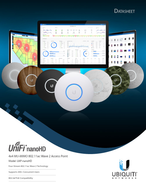
D atasheet4x4 MU-MIMO 802.11ac Wave 2 Access PointModel: UAP-nanoHDFour-Stream 802.11ac Wave 2 Technology802.3af PoE CompatibilityScalable Enterprise Wi-Fi Management UniFi® is the revolutionary Wi-Fi system that combinesenterprise performance, unlimited scalability, and a central management controller. The UniFi nanoHD AP has a refined industrial design and can be easily installed using the included mounting hardware.Easily accessible through any standard web browser and the UniFi app (iOS or Android™), the UniFi Controller software is a powerful software engine ideal forhigh-density client deployments requiring low latency and high uptime performance.Use the UniFi Controller software to quickly configure and administer an enterprise Wi-Fi network – no special training required. RF map and performance features, real-time status, automatic UAP device detection, and advanced security options are all seamlessly integrated.FeaturesSave Money and Save Time UniFi comes bundled with a non-dedicated software controller that can be deployed on an on-site PC, Mac, or Linux machine; in a private cloud; or using a public cloud service. You also have the option of deploying the compact UniFi Cloud Key with built-in software.Powerful Hardware The UniFi nanoHD AP features the latest in Wi-Fi 802.11ac Wave 2 MU-MIMO technology. Intuitive UniFi Controller Software Configure and manage your APs with the easy-to-learn user interface. Expandable Unlimited scalability: build wireless networks as big or small as needed. Start with one (or upgrade to a five‑pack) and expand to thousands while maintaining a single unified management system.Extend Your CoverageWith the UniFi Controller software running in a NOC or in the cloud, administrators can manage multiple sites: multiple, distributed deployments and multi-tenancy for managed service providers. Below are some deployment examples.D a t a s h e eUniFi ControllerPacked with FeaturesUse the UniFi Controller to provision thousands of UniFi APs, map out networks, quickly manage system traffic, and provision additional UniFi APs.View Your RF EnvironmentUse the RF environment functionality of the UniFi nanoHD AP to detect and troubleshoot nearby interference, analyze radio frequencies, choose optimal AP placement, and configure settings.Powerful RF Performance FeaturesAdvanced RF performance and configuration features include spectral analysis, airtime fairness, and band steering.Detailed AnalyticsUse the configurable reporting and analytics to manage large user populations and expedite troubleshooting.Wireless UplinkWireless Uplink functionality enables wirelessconnectivity between APs for extended range. One wired UniFi AP uplink supports up to four wireless downlinks on a single operating band, allowing wireless adoption of devices in their default state and real-time changes to network topology.Guest Portal/Hotspot SupportEasy customization and options for Guest Portals include authentication, Hotspot setup, and the ability to use your own external portal server. Use UniFi’s rate limiting for your Guest Portal/Hotspot package offerings. Apply different bandwidth rates (download/upload), limit total data usage, and limit duration of use.All UniFi APs include Hotspot functionality:• Built-in support for billing integration using major credit cards.• Built-in support for voucher-based authentication.• Built-in Hotspot Manager for voucher creation, guest management, and payment refunds.• Full customization and branding of Hotspot portal pages.Multi-Site ManagementA single UniFi Controller running in the cloud can manage multiple sites: multiple, distributed deployments and multi-tenancy for managed service providers. Each site is logically separated and has its own configuration, maps, statistics, guest portal, and administrator read/write and read-only accounts.WLAN GroupsThe UniFi Controller can manage flexible configurations of large deployments. Create multiple WLAN groups and assign them to an AP’s radio. Each WLAN can be VLAN tagged.Dynamic VLAN tagging per Wi‑Fi station (or RADIUS VLAN) is also supported.DashboardUniFi provides a visual representation of your network’s status and delivers basic information about each network segment.RF MapMonitor UniFi APs and analyze the surrounding RF environment.InsightsUniFi displays the client types for a specific time period.UniFi AppManage your UniFi devices from your smartphone or tablet.802.11ac TechnologyInitial 802.11ac Wave 1 SU-MIMO (Single-User,Multiple Input, Multiple Output) technology allows an earlier-generation AP , such as the UniFi AC Pro AP , to communicate with only one client at a time.802.11ac Wave 2 MU-MIMO (Multi-User, Multiple Input, Multiple Output) technology allows a Wave 2 AP , such as the UniFi nanoHD AP , to communicate with multiple clients at the same time – significantly increasing multi‑user throughput and overall user experience. The following describes a 5-client scenario:MU-MIMO Assuming the same conditions, a Wave 2 AP provides up to 75% improvement 1 overall over a Wave 1 AP . This improvement increases wireless performance and/or serves more clients at the same performance level.4x4 Spatial Streams At any single time, a Wave 2 AP can communicate with the following MU-MIMO clients:• four 1x1 clients • two 2x2 clients• one 2x2 client and two 1x1 clients •one 3x3 client and one 1x1 clientA 4x4 Wave 2 AP delivers up to 33% greater performance 1 than a Wave 1 AP that is 3x3 in both radio bands.Real-World Performance The UniFi nanoHD AP is the UniFi 802.11ac Wave 2 AP with the smallest form factor. Combining the performance increases from MU-MIMO technology and the use of 4x4 spatial streams, the UniFi nanoHD AP delivers up to 125% greater performance 1 than a typical Wave 1 AP .Client Compatibility For optimal performance, use MU‑MIMO clients. SU‑MIMO clients will also benefit and gain up to 10-20% greater performance when used with the UniFi nanoHD AP .1 Actual performance values may vary depending on environmental and installation conditions.Single-Client Aggregate Throughput56%ImprovementUniFi AC Pro AP UniFi nanoHD AP10-Client Aggregate Throughput238%ImprovementUniFi AC Pro AP UniFi nanoHD APMbps100-Client Aggregate Throughput900%ImprovementUniFi AC Pro AP UniFi nanoHD APMbps* MbpsHigh-Density ScenariosFor high-density environments, such as a theater where there are numerous clients in a relatively small space, we recommend the UniFi nanoHD AP when a minimal footprint is also required.Both Wave 1 and Wave 2 APs offer 28 independent(non-overlapping) channels: three for the 2.4 GHz band and twenty‑five for the 5 GHz band, including DFS channels.When you use the 2.4 GHz band in a high-density location, you encounter self-interference and channel saturation. When you use the 5 GHz band, you can deploy smaller cells (coverage areas), so you can support more clients in any cell that deploys more than one AP .With the advantages of MU-MIMO technology and 4x4 spatial streams, the UniFi nanoHD AP can support more than triple the number of users 2 than a typical Wave 1 AP .Recommended Maximum Number of UsersUniFi AC Pro AP UniFi nanoHD APUsersTheoretical Maximum Number of UsersUniFi AC Pro AP UniFi nanoHD APUsersFor more information, go to:ubnt.link/UniFi-UAPs-High-Density2 Actual numbers may vary depending on environmental and installation conditions.Client Support802.11ac Wave 1 SU-MIMOUAP-AC-PROSU-MIMO: A Wave 1 AP communicates with oneclient at a time.802.11ac Wave 2 MU-MIMOUAP-nanoHDMU-MIMO with 1x1 clients: Each client radio ofthe UniFi nanoHD AP communicates with four 1x1clients at a time.UAP-nanoHDMU-MIMO with 2x2 and 1x1 clients: Each client radioof the UniFi nanoHD AP communicates with one 2x2client and two 1x1 clients at a time.UAP-nanoHDMU-MIMO with 3x3 and 1x1 clients: Each client radioof the UniFi nanoHD AP communicates with one 3x3client and one 1x1 client at a time.EnvironmentSimultaneous Dual-Band2.4 GHz Radio Rate2.4 GHz MIMO5 GHz Radio Rate5 GHz MIMOPoE ModeCeiling MountWall MountWireless UplinkDFS CertificationCamoWoodMarbleConcreteFabricBlackHardware OverviewDeploy the UniFi nanoHD AP in high-densityenvironments requiring maximum wireless performance and minimal footprint. The UniFi nanoHD AP features simultaneous, dual-band, 4x4 MU-MIMO technology and convenient 802.3af PoE compatibility. Available in single‑ and five‑packs.Low-Profile Mounting The UniFi nanoHD AP’slow‑profile ceiling mount (sold separately) allows you to seamlessly integrate the AP into its pact Form Factor The compact design delivers a cost-effective combination of value and performance.LED The unique LED provisioning ring providesadministrator location tracking and alerts for each device.Power over Ethernet (PoE) Standard The UniFi nanoHD AP can be powered by an 802.3af PoE compliant switch. We recommend powering your UniFi devices with a UniFi PoE Switch (sold separately). The UniFi nanoHD AP is compatible with all UniFi PoE Switches and 48V adapters.Superior Processing Power The UniFi nanoHD AP is capable of complex operations (guest control, filtering, and other resource-intensive tasks) that may slow down a lesser-equipped AP .Designed for Seamless IntegrationOptional covers (sold separately) allow the UniFi nanoHD AP to discreetly blend into its setting. Choose from the following designs:AccessoriesThe use of optional accessories* makes the UniFi nanoHD AP extremely versatile in its deployment. The UniFi nanoHD AP offers a variety of mounting and stylistic options to fit your individual application needs.* All accessories sold separately.nanoHD CoversThe UniFi nanoHD AP covers allow the nanoHD AP to integrate into a wide variety of backgrounds. Whether you are mounting your AP against a marble, concrete, or wood backdrop, the UniFi nanoHD AP will blend in seamlessly. The following nanoHD cover models are available in three-packs: • nHD-cover-Fabric-3• nHD-cover-Camo-3• nHD-cover-Concrete-3• nHD-cover-Wood-3• nHD-cover-Marble-3•nHD-cover-Black-3Versatile Mounting OptionsRecessed Ceiling MountModel: nanoHD-RCM-3Use the UniFi nanoHD AP Recessed Ceiling Mount for an integrated ceiling deployment. Designed as a low‑profile mounting option, the Recessed Ceiling Mount sits discreetly within your ceiling to create a sleek look. Available in three-packs.RetroFit MountModel: nanoHD-RetroFit-3The UniFi nanoHD AP RetroFit Mount makes upgrading to the UniFi nanoHD AP quick andconvenient. The RetroFit Mount allows you to mount the UniFi nanoHD AP over existing UniFi AP mounting brackets, with no additional tools needed. Available in three-packs.SpecificationsSpecifications are subject to change. Ubiquiti products are sold with a limited warranty described at: /support/warrantyThe limited warranty requires the use of arbitration to resolve disputes on an individual basis, and, where applicable, specify arbitration instead of jury trials or class actions.©2018-2019 Ubiquiti Networks, Inc. All rights reserved. Ubiquiti, Ubiquiti Networks, the Ubiquiti U logo, the Ubiquiti beam logo, airTime, andUniFi are trademarks or registered trademarks of Ubiquiti Networks, Inc. in the United States and in other countries. Apple and the Apple logo aretrademarks of Apple Inc., registered in the U.S. and other countries. App Store is a service mark of Apple Inc., registered in the U.S. and other countries. Android, Google, Google Play, the Google Play logo and other marks are trademarks of Google LLC. All other trademarks are the property of their respectiveowners.。
ACM2012-201-2P-T002;ACM2012-900-2P-T002;ACM2012-121-2P-T002;ACM2520-301-2P;中文规格书,Datasheet资料

• All specifications are subject to change without notice.
/
001-04 / 20120610 / e9712_acm.fm
(2/3)
SHAPES AND DIMENSIONS/CIRCUIT DIAGRAMS/RECOMMENDED PC BOARD PATTERNS 2-LINE TYPE ACM2012-2P ACM2520-2P
• All specifications are subject to change without notice.
0.35
/
001-04 / 20120610 / e9712_acm.fm
0.40
(3/3)
TYPICAL ELECTRICAL CHARACTERISTICS IMPEDANCE vs. FREQUENCY CHARACTERISTICS 2-LINE ACM2012-900-2P ACM2012-121-2P
• Conformity to RoHS Directive: This means that, in conformity with EU Directive 2002/95/EC, lead, cadmium, mercury, hexavalent chromium, and specific bromine-based flame retardants, PBB and PBDE, have not been used, except for exempted applications.
2.0 ± 0.2
2.5± 0.2 1.2 ± 0.2
2.0± 0.2
1 2
4
1 2
KTY82121中文资料

1.Product profile1.1General descriptionThe temperature sensors in the KTY82 series have a positive temperature coefficient of resistance and are suitable for use in measurement and control systems.The sensors are encapsulated in the small plastic Surface Mounted Device (SMD) SOT23 package.Other special selections are available on request.1.2Features1.3Quick reference dataKTY82 seriesSilicon temperature sensorsRev. 04 — 14 January 2008Product data sheetI High accuracy and reliability I Long-term stabilityI Positive temperature coefficient;fail-safe behaviorI Virtually linear characteristicsTable 1.Quick reference dataT amb =25°C; in liquid; unless otherwise specified.Symbol Parameter Conditions MinTypMaxUnitR 25sensor resistanceI sen(cont)=1mA KTY82/110990-1010ΩKTY82/120980-1020ΩKTY82/121980-1000ΩKTY82/1221000-1020ΩKTY82/150950-1050ΩKTY82/151950-1000ΩKTY82/2101980-2020ΩKTY82/2201960-2040ΩKTY82/2211960-2000ΩKTY82/2222000-2040ΩKTY82/2501900-2100ΩKTY82/2511900-2000ΩKTY82/2522000-2100Ω2.Pinning information3.Ordering informationTable 2.Pinning Pin Description Simplified outline1electrical contact 2electrical contact3substrate (must remain potential free)123Table 3.Ordering informationType numberPackage NameDescriptionVersion KTY82/110-plastic surface-mounted package; 3leadsSOT23KTY82/120KTY82/121KTY82/122KTY82/150KTY82/151KTY82/210KTY82/220KTY82/221KTY82/222KTY82/250KTY82/251KTY82/2524.MarkingTable 4.Marking codesType number Marking codeKTY82/110110KTY82/120120KTY82/121121KTY82/122122KTY82/150150KTY82/151151KTY82/210210KTY82/220220KTY82/221221KTY82/222222KTY82/250250KTY82/251251KTY82/2522525.Limiting valuesTable 5.Limiting valuesIn accordance with the Absolute Maximum Rating System (IEC 60134).Symbol Parameter Conditions Min Max UnitI sen(cont)continuous sensor current in free air; T amb=25°C-10mAin free air; T amb=150°C-2mA T amb ambient temperature−55+150°C6.Characteristics[1]The thermal time constant is the time taken for the sensor to reach 63.2% of the total temperature difference. For example, if a sensor with a temperature of 25°C is moved to an environment with an ambient temperature of 100°C, the time for the sensor to reach a temperature of 72.4°C is the thermal time constant.Table 6.CharacteristicsT amb =25°C; in liquid; unless otherwise specified.Symbol Parameter Conditions Min Typ Max Unit R 25sensor resistanceI sen(cont)=1mA KTY82/110990-1010ΩKTY82/120980-1020ΩKTY82/121980-1000ΩKTY82/1221000-1020ΩKTY82/150950-1050ΩKTY82/151950-1000ΩKTY82/2101980-2020ΩKTY82/2201960-2040ΩKTY82/2211960-2000ΩKTY82/2222000-2040ΩKTY82/2501900-2100ΩKTY82/2511900-2000ΩKTY82/2522000-2100ΩTC temperature coefficient -0.79-%/KR 100/R 25resistance ratio T amb =100°C and 25°C 1.676 1.696 1.716R −55/R 25resistance ratioT amb =−55°C and 25°C 0.4800.4900.500∆R 25drift of sensor resistance at 25°C10000h continuousoperation; T amb =150°C KTY82/1 series - 1.6-ΩKTY82/2 series- 3.2-Ωτththermal time constantin still air [1]-7-s in still liquid [1]-1-s in flowing liquid[1]-0.5-sTable 7.Ambient temperature, corresponding resistance, temperature coefficient and maximum expected temperature error for KTY82/110 and KTY82/120I sen(cont)=1mA.Ambient temperature Temperaturecoefficient(%/K)KTY82/110KTY82/120(°C)(°F)Resistance (Ω)Temperatureerror (K)Resistance (Ω)Temperatureerror (K)Min Typ Max Min Typ Max−55−670.99475490505±3.024********±4.02−50−580.98500515530±2.92495515535±3.94−40−400.96552567582±2.74547567588±3.78−30−220.93609624638±2.55603624645±3.62−20−40.91669684698±2.35662684705±3.45−10140.88733747761±2.14726747769±3.27 0320.85802815828±1.91793815836±3.08 10500.83874886898±1.67865886907±2.88 20680.80950961972±1.41941961982±2.66 25770.7999010001010±1.2798010001020±2.54 30860.78102910401051±1.39101810401061±2.68 401040.75110811221136±1.64109711221147±2.97 501220.73119212091225±1.91118012091237±3.28 601400.71127812991319±2.19126512991332±3.61 701580.69136913921416±2.49135513921430±3.94 801760.67146214901518±2.8144714901532±4.3 901940.65155915911623±3.12154315911639±4.66 1002120.63165916961733±3.46164216961750±5.05 1102300.61176218051847±3.83174418051865±5.48 1202480.58186719151963±4.33184819151982±6.07 1252570.55191919702020±4.66189919702040±6.47 1302660.52197020232077±5.07195020232097±6.98 1402840.45206521242184±6.28204321242205±8.51 1503020.35214522112277±8.55212322112299±11.43Table 8.Ambient temperature, corresponding resistance, temperature coefficient and maximum expected temperature error for KTY82/121 and KTY82/122I sen(cont)=1mA.Ambient temperature Temperaturecoefficient(%/K)KTY82/121KTY82/122(°C)(°F)Resistance (Ω)Temperatureerror (K)Resistance (Ω)Temperatureerror (K)Min Typ Max Min Typ Max−55−670.99471485500±3.024********±3.02−50−580.98495510524±2.92505520535±2.92−40−400.96547562576±2.74558573588±2.74−30−220.93603617632±2.55615630645±2.55−20−40.91662677691±2.35676690705±2.35−10140.88726740754±2.14741755769±2.14 0320.85794807820±1.91810823836±1.91 10500.83865877889±1.67883895907±1.67 20680.80941951962±1.41960971982±1.41 25770.799809901000±1.27100010101020±1.27 30860.78101810291041±1.39103910501062±1.39 401040.75109711111125±1.64112011341148±1.64 501220.73118011961213±1.91120412211238±1.91 601400.71126612861305±2.19129113121332±2.19 701580.69135513781402±2.49138214061430±2.49 801760.67144714751502±2.8147715051533±2.8 901940.65154315751607±3.12157416071639±3.12 1002120.63164216791716±3.46167617131750±3.46 1102300.61174517861828±3.83178018231865±3.83 1202480.58184918961943±4.33188619341982±4.33 1252570.55190019502000±4.66193819892041±4.66 1302660.52195020032056±5.07198920442098±5.07 1402840.45204421032162±6.28208521462206±6.28 1503020.35212421892254±8.55216722332299±8.55Table 9.Ambient temperature, corresponding resistance, temperature coefficient and maximum expected temperature error for KTY82/150 and KTY82/151I sen(cont)=1mA.Ambient temperature Temperaturecoefficient(%/K)KTY82/150KTY82/151(°C)(°F)Resistance (Ω)Temperatureerror (K)Resistance (Ω)Temperatureerror (K)Min Typ Max Min Typ Max−55−670.99456490524±7.04456478499±4.52−50−580.98479515550±6.99480502524±4.45−40−400.96530567605±6.91530553576±4.3−30−220.93584624663±6.84584608632±4.16−20−40.91642684725±6.77642667691±4.01−10140.88703747791±6.69704729753±3.84 0320.85769815861±6.61770794819±3.67 10500.83838886934±6.51839864889±3.48 20680.809129611010±6.41912937962±3.28 25770.7995010001050±6.359509751000±3.18 30860.7898710401093±6.5598810141040±3.33 401040.75106411221181±6.97106410941124±3.64 501220.73114312091274±7.4114411781212±3.97 601400.71122612991371±7.85122712661305±4.31 701580.69131313921472±8.31131413571401±4.67 801760.67140214901577±8.79140414531501±5.05 901940.65149515911687±9.29149715511606±5.43 1002120.63159116961801±9.81159316541714±5.84 1102300.61169018051919±10.4169217591827±6.3 1202480.58179119152039±11.28179218671942±6.94 1252570.55184019702099±11.91184219201999±7.38 1302660.52188920232158±12.72189119732055±7.94 1402840.45198021242269±15.21198220712161±9.63 1503020.35205722112365±20.09205921562252±12.88Table 10.Ambient temperature, corresponding resistance, temperature coefficient and maximum expected temperature error for KTY82/210 and KTY82/220I sen(cont)=1mA.Ambient temperature Temperaturecoefficient(%/K)KTY82/210KTY82/220(°C)(°F)Resistance (Ω)Temperatureerror (K)Resistance (Ω)Temperatureerror (K)Min Typ Max Min Typ Max−55−670.999519801009±3.029*********±4.02−50−580.98100010301059±2.9299010301070±3.94−40−400.96110511351165±2.74109411351176±3.78−30−220.93121812471277±2.55120512471289±3.62−20−40.91133813671396±2.35132513671410±3.45−10140.88146714951523±2.14145214951538±3.27 0320.85160316301656±1.91158716301673±3.08 10500.83174817721797±1.67173017721814±2.88 20680.80190119221944±1.41188119221963±2.66 25770.79198020002020±1.27196020002040±2.54 30860.78205720802102±1.39203620802123±2.68 401040.75221722452272±1.64219422452295±2.97 501220.73238324172451±1.91235924172475±3.28 601400.71255725972637±2.19253125972663±3.61 701580.69273727852832±2.49270927852860±3.94 801760.67292429803035±2.8289429803065±4.3 901940.65311831823246±3.12308631823278±4.66 1002120.63331833923466±3.46328433923500±5.05 1102300.59352336073691±3.93348736073728±5.61 1202480.53372238173912±4.7368338173950±6.59 1252570.49381539154016±5.26377539154055±7.31 1302660.44390140084114±6386140084154±8.27 1402840.33404941664283±8.45400841664325±11.46 1503020.20415342804407±14.63411042804450±19.56Table 11.Ambient temperature, corresponding resistance, temperature coefficient and maximum expected temperature error for KTY82/221 and KTY82/222I sen(cont)=1mA.Ambient temperature Temperaturecoefficient(%/K)KTY82/221KTY82/222(°C)(°F)Resistance (Ω)Temperatureerror (K)Resistance (Ω)Temperatureerror (K)Min Typ Max Min Typ Max−55−670.99941970999±3.029*********±3.02−50−580.9899010191049±2.92101010401070±2.92−40−400.96109411231153±2.74111611461176±2.74−30−220.93120512351264±2.55123012601290±2.55−20−40.91132513541382±2.35135213811410±2.35−10140.88145214801508±2.14148115101538±2.14 0320.85158716131640±1.91161916461673±1.91 10500.83173017541779±1.67176517901815±1.67 20680.80188219031924±1.41192019411963±1.41 25770.79196019802000±1.27200020202040±1.27 30860.78203720592081±1.39207821002123±1.39 401040.75219522222250±1.64223922672295±1.64 501220.73236023932426±1.91240724412475±1.91 601400.71253125712611±2.19258226232664±2.19 701580.69271027572804±2.49276428122860±2.49 801760.67289529503005±2.8295330093065±2.8 901940.65308631503214±3.12314932143279±3.12 1002120.63328533583431±3.46335134263501±3.46 1102300.59348835713655±3.93355836433728±3.93 1202480.53368437793873±4.7375938553951±4.7 1252570.49377638763976±5.26385339554056±5.26 1302660.44386239674073±6394040484155±6 1402840.33400941254241±8.45409042084326±8.45 1503020.20411242374363±14.63419543234451±14.63Table 12.Ambient temperature, corresponding resistance, temperature coefficient and maximum expected temperature error for KTY82/250 and KTY82/251I sen(cont)=1mA.Ambient temperature Temperaturecoefficient(%/K)KTY82/250KTY82/251(°C)(°F)Resistance (Ω)Temperatureerror (K)Resistance (Ω)Temperatureerror (K)Min Typ Max Min Typ Max−55−670.999119801049±7.04913956999±4.52−50−580.9895910301101±6.9996010041048±4.45−40−400.96106011351210±6.91106111061152±4.3−30−220.93116812471327±6.84116912161263±4.16−20−40.91128313671451±6.77128513331381±4.01−10140.88140714951583±6.69140814571507±3.84 0320.85153816301721±6.61153915891639±3.67 10500.83167717721867±6.51167817281778±3.48 20680.80182419222021±6.41182518741923±3.28 25770.79190020002100±6.35190019502000±3.18 30860.78197420802185±6.55197520282080±3.33 401040.75212722452362±6.97212921892248±3.64 501220.73228724172547±7.4228923572425±3.97 601400.71245325972741±7.85245525322609±4.31 701580.69262627852943±8.31262827152802±4.67 801760.67280529803154±8.79280729053003±5.05 901940.65299031823374±9.29299331023212±5.43 1002120.63318233923602±9.81318533073429±5.84 1102300.59337936073836±10.65338235173652±6.45 1202480.53356938174065±12.25357337213870±7.53 1252570.49365839154173±13.45366238173973±8.33 1302660.44374140084274±15.06374539074070±9.4 1402840.33388341664450±20.49388740624237±12.96 1503020.20398242804578±34.35398741734359±22.02Table 13.Ambient temperature, corresponding resistance, temperature coefficient and maximum expected temperature error for KTY82/252I sen(cont)=1mA.Ambient temperature Temperaturecoefficient(%/K)KTY82/252(°C)(°F)Resistance (Ω)Temperatureerror (K)Min Typ Max−55−670.9995910051050±4.52−50−580.98100910551102±4.45−40−400.96111511631211±4.3−30−220.93122912781328±4.16−20−40.91135114011452±4.01−10140.88148015321584±3.84 0320.85161816701723±3.67 10500.83176418171869±3.48 20680.80191919702022±3.28 25770.79200020502100±3.18 30860.78207721322187±3.33 401040.75223823012364±3.64 501220.73240624782549±3.97 601400.71258126622743±4.31 701580.69276328542946±4.67 801760.67295130543157±5.05 901940.65314732623376±5.43 1002120.63334934773605±5.84 1102300.59355636973839±6.45 1202480.53375639124068±7.53 1252570.49385040134177±8.33 1302660.44393741084278±9.4 1402840.33408742714455±12.96 1503020.20419143874583±22.02To keep the temperature error low, an operating current of I sen(cont)=1mA is recommended for temperatures above 100°Ca.KTY82/1 seriesb.KTY82/2 seriesFig 1.Sensor resistance as a function of operating currentmgg699213R (k Ω)0I sen(cont) (mA)10−1101150 °C 125 °C 100 °C 75 °C 50 °C25 °C 0 °C −25 °C −50 °Cmgg70023145R (k Ω)0I sen(cont) (mA)10−1101150 °C125 °C 100 °C75 °C 50 °C25 °C 0 °C −25 °C−50 °CT amb =25°C T amb =25°Ca.KTY82/1 seriesb.KTY82/2 seriesFig 2.Deviation of sensor resistance as a function of operating currentmgg704I sen(cont) (mA)0211020∆R (Ω)−10mgg703I sen(cont) (mA)21102030∆R (Ω)−107.Package outline8.Handling informationKTY82 series temperature sensors are sensitive to ElectroStatic Discharge (ESD).ESD can lead to irreversible changes of the characteristic.Fig 3.Maximum operating current for safe operationmgg705T amb (°C)−501501000504812I sen(cont)(mA)0Fig 4.Minimized package outline SOT2304-11-04Dimensions in mm0.450.151.91.10.93.02.82.52.1 1.41.20.480.380.150.091239.SolderingFig 5.Reflow soldering footprint SOT23Fig 6.Wave soldering footprint SOT23solder resistoccupied areasolder landssolder paste Dimensions in mmsot0231.000.60(3x)1.301232.503.000.85 2.702.900.50 (3x)0.60 (3x)3.300.85sot0234.004.60 2.804.501.203.403211.20 (2x)preferred transport direction during solderingDimensions in mmsolder resist occupied areasolder lands10.Revision historyTable 14.Revision historyDocument ID Release date Data sheet status Change notice SupersedesKTY82_SER_420080114Product data sheet-KTY82-2SERIES_3KTY82-1SERIES_3 Modifications:•The format of this data sheet has been redesigned to comply with the new identityguidelines of NXP Semiconductors.•Legal texts have been adapted to the new company name where appropriate.KTY82-2SERIES_319980326Product specification--KTY82-1SERIES_319980326Product specification--11.Legal information11.1Data sheet status[1]Please consult the most recently issued document before initiating or completing a design.[2]The term ‘short data sheet’ is explained in section “Definitions”.[3]The product status of device(s)described in this document may have changed since this document was published and may differ in case of multiple devices.The latest product status information is available on the Internet at URL .11.2DefinitionsDraft —The document is a draft version only. The content is still under internal review and subject to formal approval, which may result in modifications or additions. NXP Semiconductors does not give any representations or warranties as to the accuracy or completeness ofinformation included herein and shall have no liability for the consequences of use of such information.Short data sheet —A short data sheet is an extract from a full data sheet with the same product type number(s)and title.A short data sheet is intended for quick reference only and should not be relied upon to contain detailed and full information. For detailed and full information see the relevant full data sheet, which is available on request via the local NXP Semiconductors sales office. In case of any inconsistency or conflict with the short data sheet, the full data sheet shall prevail.11.3DisclaimersGeneral —Information in this document is believed to be accurate andreliable.However,NXP Semiconductors does not give any representations or warranties,expressed or implied,as to the accuracy or completeness of such information and shall have no liability for the consequences of use of such information.Right to make changes —NXP Semiconductors reserves the right to make changes to information published in this document, including withoutlimitation specifications and product descriptions, at any time and without notice.This document supersedes and replaces all information supplied prior to the publication hereof.Suitability for use —NXP Semiconductors products are not designed,authorized or warranted to be suitable for use in medical, military, aircraft,space or life support equipment, nor in applications where failure ormalfunction of an NXP Semiconductors product can reasonably be expected to result in personal injury, death or severe property or environmentaldamage. NXP Semiconductors accepts no liability for inclusion and/or use of NXP Semiconductors products in such equipment or applications and therefore such inclusion and/or use is at the customer’s own risk.Applications —Applications that are described herein for any of these products are for illustrative purposes only. NXP Semiconductors makes no representation or warranty that such applications will be suitable for the specified use without further testing or modification.Limiting values —Stress above one or more limiting values (as defined in the Absolute Maximum Ratings System of IEC 60134)may cause permanent damage to the device.Limiting values are stress ratings only and operation of the device at these or any other conditions above those given in theCharacteristics sections of this document is not implied. Exposure to limiting values for extended periods may affect device reliability.Terms and conditions of sale —NXP Semiconductors products are sold subject to the general terms and conditions of commercial sale,as published at /profile/terms , including those pertaining to warranty,intellectual property rights infringement and limitation of liability, unless explicitly otherwise agreed to in writing by NXP Semiconductors. In case of any inconsistency or conflict between information in this document and such terms and conditions, the latter will prevail.No offer to sell or license —Nothing in this document may be interpreted or construed as an offer to sell products that is open for acceptance or the grant,conveyance or implication of any license under any copyrights,patents or other industrial or intellectual property rights.Quick reference data —The Quick reference data is an extract of theproduct data given in the Limiting values and Characteristics sections of this document, and as such is not complete, exhaustive or legally binding.11.4TrademarksNotice:All referenced brands,product names,service names and trademarks are the property of their respective owners.12.Contact informationFor more information, please visit:For sales office addresses, please send an email to:salesaddresses@Document status [1][2]Product status [3]DefinitionObjective [short] data sheet Development This document contains data from the objective specification for product development.Preliminary [short] data sheet Qualification This document contains data from the preliminary specification.Product [short] data sheetProductionThis document contains the product specification.13.Contents1Product profile. . . . . . . . . . . . . . . . . . . . . . . . . . 11.1General description. . . . . . . . . . . . . . . . . . . . . . 11.2Features . . . . . . . . . . . . . . . . . . . . . . . . . . . . . . 11.3Quick reference data. . . . . . . . . . . . . . . . . . . . . 12Pinning information. . . . . . . . . . . . . . . . . . . . . . 23Ordering information. . . . . . . . . . . . . . . . . . . . . 24Marking. . . . . . . . . . . . . . . . . . . . . . . . . . . . . . . . 35Limiting values. . . . . . . . . . . . . . . . . . . . . . . . . . 36Characteristics. . . . . . . . . . . . . . . . . . . . . . . . . . 47Package outline . . . . . . . . . . . . . . . . . . . . . . . . 138Handling information. . . . . . . . . . . . . . . . . . . . 139Soldering . . . . . . . . . . . . . . . . . . . . . . . . . . . . . 1410Revision history. . . . . . . . . . . . . . . . . . . . . . . . 1511Legal information. . . . . . . . . . . . . . . . . . . . . . . 1611.1Data sheet status . . . . . . . . . . . . . . . . . . . . . . 1611.2Definitions. . . . . . . . . . . . . . . . . . . . . . . . . . . . 1611.3Disclaimers. . . . . . . . . . . . . . . . . . . . . . . . . . . 1611.4T rademarks. . . . . . . . . . . . . . . . . . . . . . . . . . . 1612Contact information. . . . . . . . . . . . . . . . . . . . . 1613Contents. . . . . . . . . . . . . . . . . . . . . . . . . . . . . . 17Please be aware that important notices concerning this document and the product(s)described herein, have been included in section ‘Legal information’.© NXP B.V.2008.All rights reserved.For more information, please visit: For sales office addresses, please send an email to: salesaddresses@Date of release: 14 January 2008。
smc-diodes ssr811 ssr812 datasheet说明书

Technical Data Reset Circuits with Manual Reset Input Data Sheet N1594 Rev. -• China - Germany - Korea - Singapore - United States • •http://***************************************•SSR811/SSR812Description:SSR811/SSR812 are low-power microprocessor (μP) supervisory circuits used to monitor power supplies in μP and digital systems. They provide applications with benefits of circuit reliability and low cost by eliminating external components. SSR811/SSR812 also offer a manual reset input.These devices perform as valid singles in applications with Vcc ranging from 6.0V down to 0.9V. The reset signal lasts for a minimum period of 140ms whenever VCC supply voltage falls below preset threshold. Both SSR811 and SSR812 were designed with a reset comparator to help identify invalid signals, which last less than 140ms. The only difference between them is that they have an active-low R E S E T ————————output and active-high RESET output, respectively.Low supply current (1μA) makes SSR811/SSR812 ideal for portable equipment. The devices are available in SOT-23-5 package.Features:• Ultra Low Supply Current 1μA(typ.) • Guaranteed Reset Valid to Vcc=0.9V• Available in two Output Types: Push-Pull Active Low (SSR811), Push-Pull Active High (SSR812)• 140ms Min. Power-On Reset Pulse Width• Internally Fixed Threshold 2.3V, 2.6V, 2.7V, 2.9V, 3.1V, 4.0V, 4.4V, and 4.6V • Tight Voltage Threshold Tolerance: 1.5% •Low Profile Package: SOT-23-5.Applications:• Notebook Computers • Digital Still Cameras • PDAs•Critical Microprocessor MonitoringTypical application circuit:Technical Data Reset Circuits with Manual Reset Input Data Sheet N1594 Rev. -• China - Germany - Korea - Singapore - United States • •http://***************************************•SSR811/SSR812Ordering Information: SSR811 -XXXXXMarking Diagram:PIN CONFIGURATIONSOT-23-5TOP VIEW 1: GND 2: NC3: R E S E T ————————(RESET)4: MR ———5: VCCPart No. MarkingSSR811-26DTR BQ26G SSR811-29DTR BQ29G SSR811-31DTR BQ31G SSR811-44DTR BQ44G SSR811-46DTR BQ46GSSR812-23DTR BR23GSSR812-26DTR BR26GSSR812-29DTR BR29G SSR812-31DTR BR31GSSR812-40DTR BR40GSSR812-44DTR BR44GSSR812-46DTR BR46GTechnical Data Reset Circuits with Manual Reset Input Data Sheet N1594 Rev. -• China - Germany - Korea - Singapore - United States • •http://***************************************•SSR811/SSR812Absolute Maximum Ratings:V CC ………..................…………………………………………………………………………….-0.3V~6.5V RESET, R E S E T ————————………………………...............……………………………………-0.3V ~ (VCC+0.3V) Input Current (V CC, MR ———)………………………………………………………………….................. 20mA Output Current (RESET or R E S E T ————————)………………………...............……………………………20mA Continuous Power Dissipation (T A = +70°C) ...……………………………………………….. 320mW Operating Junction Temperature Range ...………………………………………….… –40°C to 85°C Junction Temperature ………………………………………………………………………………..125°C Storage Temperature Range ……………………………………………………………..–65°C ~ 150°C Lead Temperature (Soldering) 10 sec. ……………………………………………………………260°CAbsolute Maximum Ratings are those values beyond which the life of a device may be impaired.Test CircuitTechnical Data Reset Circuits with Manual Reset Input Data Sheet N1594 Rev. -• China - Germany - Korea - Singapore - United States ••http://***************************************•SSR811/SSR812Electrical Characteristics (Typical values are at T A =25°C, unless otherwise specified.) (Note 1)Note: 1. Specifications are production tested at T A =25°C. Specifications over the -40°C to 85°C operatingtemperature range are assured by design, characterization and correlation with Statistical Quality Controls (SQC). 2. R E S E T ————————output is for SSR811; RESET output is for SSR812.Technical Data Reset Circuits with Manual Reset Input Data Sheet N1594 Rev. -• China - Germany - Korea - Singapore - United States • •http://***************************************•SSR811/SSR812Typical Performance CharacteristicsTechnical Data Reset Circuits with Manual Reset Input Data Sheet N1594 Rev. -• China - Germany - Korea - Singapore - United States • •http://***************************************•SSR811/SSR812Block DiagramPin DescriptionsGND Pin : Ground.RESET ———————Pin (SSR811) : Active low output pin. RESET ———————Output remains low while Vcc is below the resetthreshold.RESET Pin (SSR812) : Active high output pin. RESET output remains high while Vcc is below the resetthreshold. MR ——— Pin : Logic low manual reset input. This active-low input has an internal 20k Ω pull-upresistor. It can be driven by a TTL or CMOS, or shorted to ground with a switch. Leave open when unused.Vcc Pin : Supply voltage.Technical Data Reset Circuits with Manual Reset Input Data Sheet N1594 Rev. -• China - Germany - Korea - Singapore - United States • •http://***************************************•SSR811/SSR812Detail Descriptions of Technical TermsRESET OUTPUTμP will be activated at a valid reset state. These μP supervisory circuits assert reset to prevent code execution errors during power-up, power-down, or brownout conditions.RESET ———————is guaranteed to be a logic low for V TH>VCC>0.9V. Once VCC exceeds the reset threshold, an internal timer keeps RESET ———————low for the reset timeout period; after this interval, RESET ———————goes high.If a brownout condition occurs (VCC drops below the reset threshold), RESET ———————goes low. Any time VCC goes below the reset threshold, the internal timer resets to zero, and RESET ———————goes low. The internal timer is activated after VCC returns above the reset threshold, and RESET ———————remains low for the reset timeout period. The manual reset input (MR ———) can also initiate a reset. SSR812 has an active-high RESET output that is the inverse of SSR811’s RESET ———————output.MANUAL RESET INPUTMany μP-based products require manual reset capability, allowing operators, test technicians, or external logic circuitry to initiate a reset. Logic low on MR ———asserts reset. Reset will remain asserted for the Reset Active Timeout Period (t RP) after MR ———returns high. This input has an internal 20K Ω pull-up resistor, so it can be floating if it is not used. MR ———can be driven with TTL or CMOS-logic levels, or with open-drain/collector outputs. Another alternative is to connect a normal switch from MR ———to GND to create a manual reset function. Connecting a 0.1μF capacitor from MR ———to ground can provide noise immunity to prevent noise caused by long cables of MR ———or noisy environment.BENEFITS OF HIGHLY ACCURATE RESET THRESHOLDSSR811/SSR812 with specified voltage as 5V±10% or 3V±10% are ideal for systems using a 5V±5% or 3V±5% power supply. The reset is guaranteed to assert after the power supply falls out of regulation, but before power drops below the minimum specified operating voltage range of the system ICs. The pre-trimmed thresholds are reducing the range over which an undesirable reset may occur.Technical Data Reset Circuits with Manual Reset Input Data Sheet N1594 Rev. -• China - Germany - Korea - Singapore - United States • •http://***************************************•SSR811/SSR812Application InformationNEGATIVE-GOING VCC TRANSIENTSIn addition to issuing a reset to the μP during power-up, power-down, and brownout conditions, SSR811 series are relatively resistant to short-duration negative-going VCC transient. ENSURING A VALID RESET OUTPUT DOWN TO VCC=0When VCC falls below 0.9V, SSR811 RESET ———————output no longer sinks current; it becomes an open circuit. In this case, high-impedance CMOS logic inputs connecting to RESET ———————can drift to undetermined voltages. Therefore, SSR811/SSR812 with CMOS is perfect for most applications of VCC below 0.9V. However in applications where RESET ———————must be valid down to 0V, adding a pull-down resistor to RESET ———————causes any leakage currents to flow to ground, holding RESET ———————low. INTERFACING TO μP WITH BIDIRECTIONAL RESET PINSμPs with bidirectional reset pins can contend with SSR811/812 reset outputs. If SSR811 RESET ———————output is asserted high and the μP wants to pull it low, indeterminate logic levels may occur. To correct such cases, connect a resistor between SSR811 RESET ———————(or SSR812 RESET ———————) output and the μP reset I/O. Buffer the reset output to other system components.Technical Data Reset Circuits with Manual Reset Input Data Sheet N1594 Rev. - • China - Germany - Korea - Singapore - United States • •http://***************************************•SSR811/SSR812Physical DimensionsSOT-23-5 (unit: mm)Note : 1. Refer to JEDEC MO-178AA.2. Dimension "D" does not include mold flash, protrusions or gate burrs. Mold flash, protrusion or gate burrs shall not exceed 10 mil per side.3. Dimension "E1" does not include inter-lead flash or protrusions.4. Controlling dimension is millimeter, converted inch dimensions are not necessarily exact.Technical Data Reset Circuits with Manual Reset Input Data Sheet N1594 Rev. -• China - Germany - Korea - Singapore - United States • •http://***************************************•SSR811/SSR812DISCLAIMER:1- The information given herein, including the specifications and dimensions, is subject to change without prior notice to improve product characteristics. Before ordering, purchasers are advised to contact the SMC - Sangdest Microelectronics (Nanjing) Co., Ltd sales department for the latest version of the datasheet(s).2- In cases where extremely high reliability is required (such as use in nuclear power control, aerospace and aviation, traffic equipment, medical equipment , and safety equipment) , safety should be ensured by using semiconductor devices that feature assured safety or by means of users’ fail-safe precautions or other arrangement .3- In no event shall SMC - Sangdest Microelectronics (Nanjing) Co., Ltd be liable for any damages that may result from an accident or any other cause during operation of the user’s units according to the datasheet(s). SMC - Sangdest Microelectronics (Nanjing) Co., Ltd assumes no responsibility for any intellectual property claims or any other problems that may result from applications of information, products or circuits described in the datasheets.4- In no event shall SMC - Sangdest Microelectronics (Nanjing) Co., Ltd be liable for any failure in a semiconductor device or any secondary damage resulting from use at a value exceeding the absolute maximum rating.5- No license is granted by the datasheet(s) under any patents or other rights of any third party or SMC - Sangdest Microelectronics (Nanjing) Co., Ltd.6- The datasheet(s) may not be reproduced or duplicated, in any form, in whole or part, without the expressed written permission of SMC - Sangdest Microelectronics (Nanjing) Co., Ltd.7- The products (technologies) described in the datasheet(s) are not to be provided to any party whose purpose in their application will hinder maintenance of international peace and safety nor are they to be applied to that purpose by their direct purchasers or any third party. When exporting these products (technologies), the necessary procedures are to be taken in accordance with related laws and regulations..。
S-812C20AMC-C2AT2G中文资料
ESP8089_WiFi 数据手册 中文

ESP8089 802.11bgn 芯片组
7
7.1
规格
功耗
下列功耗数据是基于 3.3V 的电源、25C 的周围温度,并使用内部稳压器测得。 [1] 所有测量均在没有 SAW 滤波器的情况下,于天线接口处完成。 [2] 所有发射数据是基于 90% 的占空比,在持续发射的模式下测得的。
模式 传送 802.11b, CCK 1Mbps, POUT=+19.5dBm 传送 802.11b, CCK 11Mbps, POUT=+18.5dBm 传送 802.11g, OFDM 54Mbps, POUT =+16dBm 传送 802.11n, MCS7, POUT =+14dBm 接收 802.11b, 包长 1024 字节, -80dBm 接收 802.11g, 包长 1024 字节, -70dBm 接收 802.11n, 包长 1024 字节, -65dBm 系统待机模式 深度睡眠 节能模式 DTIM 1 节能模式 DTIM 3 关机 最小值 通常 215 197 145 135 60 60 62 0.9 10 1.2 0.86 0.5 最大值 单位 mA mA mA mA mA mA mA mA uA mA mA uA
otlsopeapoleaposimoakao或视客户要求而定?80211n支持24ghz5ghz?支持mimo1?1and2?1stbcampdu和amsdu聚合04?s的保护间隔?wmm节能uapsd?采用带qos的多队列管理实现符合80211e标准的多媒体数据流量优化方式?遵循uma并通过uma认证?8021hrfc1042帧封装?散列dma进行数据转移操作使cpu占用率达到最小?天线分集与选择由软件管理的硬件?将时钟电源门控与遵循80211标准的功率管理结合起来根据当前连接情况进行动态调节以实现最低能耗?可调节比率演算法则根据实际的snr和信息包丢失数据设定最优传送率和tx功率?mac层自动重传与自动回应避免主机运行缓慢时发生丢包现象?无缝漫游支持?可配置的数据包交通仲裁与为其量身定做基于从机处理器的设计结合为一系列蓝牙芯片销售商提供灵活且精确的分时蓝牙共存支持?支持双单天线蓝牙共存具备同步接收wifi蓝牙的能力20page乐鑫信息科技2013年9月28日esp808980211bgn芯片组10电源管理芯片可以调成以下状态
VLF4012AT-4R7M1R1;VLF4012AT-100MR79;VLF4012AT-3R3M1R3;VLF4012AT-2R2M1R5;中文规格书,Datasheet资料
Inductance tolerance(%) ±30 ±20 ±20 ±20 ±20 ±20 ±20
Test frequency (kHz) 100 100 100 100 100 100 100
DC resistance( ) max. 0.054 0.1 0.15 0.2 0.31 0.46 1.20 typ. 0.047 0.091 0.13 0.1R7
2.8±0.2
1.4max. Dimensions in mm
RECOMMENDED PC BOARD PATTERN
1.2 2.1 3.4 Dimensions in mm
Inductance [at 1/2 Idc1]3 (µH) 1 2.2 3.3 4.7 6.8 10 22
• All specifications are subject to change without notice.
/
001-04 / 20120310 / e531_vlf
(3/17)
Inductors for Power Circuits Wound/STD • Magnetic Shielded
Part No. VLF3014AT-1R0N1R7 VLF3014AT-2R2M1R2 VLF3014AT-3R3M1R0 VLF3014AT-4R7MR90 VLF3014AT-6R8MR72 VLF3014AT-100MR59 VLF3014AT-220MR37
1
SHAPES AND DIMENSIONS
VLF-MT Series VLF302510MT
With the VLF302510MT Series, a DC to DC converter with topclass voltage conversion efficiency for similar size products was achieved by optimizing the magnetic material and configuration. These products are optimal for use as choke coils in switching power supplies such as those in mobile devices requiring spacesaving design. FEATURES • Miniature size Mount area: 3.02.5mm Low profile: 1.0mm max. height • Generic use for portable DC to DC converter line. • High magnetic shield construction should actualize high resolution for EMC protection. • The products contain no lead and also support lead-free soldering. • The products is halogen-free. • It is a product conforming to RoHS directive. APPLICATIONS Smartphones, cellular phones, DSCs, DVCs, HDDs, LCD displays, compact power supply modules, etc. SHAPES AND DIMENSIONS
xRTL8812AU_DataSheet_R02_May-24-2012

TRADEMARKS Realtek is a trademark of Realtek Semiconductor Corporation. Other names mentioned in this document are trademarks/registered trademarks of their respective owners.
PIN ASSIGNMENTS ......................................................................................................................................................... 6 4.1. PACKAGE IDENTIFICATION ............................................................................................................................................ 7
Single-Chip IEEE 802.11a/b/g/n/ac 2T2R WLAN Controller with USATR-2265-11 Rev. 0.2
RTL8812AU Datasheet
List of Tables
TABLE 1. TABLE 2. TABLE 3. TABLE 4. TABLE 5. TABLE 6. TABLE 7. TABLE 8. USB TRANSCEIVER INTERFACE ....................................................................................................................................... 7 POWER PINS .................................................................................................................................................................... 8 RF INTERFACE ................................................................................................................................................................ 8 LED INTERFACE ............................................................................................................................................................. 9 CLOCK AND OTHER PINS ................................................................................................................................................. 9 TEMPERATURE LIMIT RATINGS ...................................................................................................................................... 11 DC CHARACTERISTICS .................................................................................................................................................. 11 ORDERING INFORMATION .............................................................................................................................................. 14
- 1、下载文档前请自行甄别文档内容的完整性,平台不提供额外的编辑、内容补充、找答案等附加服务。
- 2、"仅部分预览"的文档,不可在线预览部分如存在完整性等问题,可反馈申请退款(可完整预览的文档不适用该条件!)。
- 3、如文档侵犯您的权益,请联系客服反馈,我们会尽快为您处理(人工客服工作时间:9:00-18:30)。
SM802112ClockWorks ™ 3-Output, 480MHz/80MHz,Ultra-Low Jitter LVDS/CMOS Frequency SynthesizerClockWorks is a trademark of Micrel, IncRotaryWave is a registered trademark of Multigig, Inc.Micrel Inc. • 2180 Fortune Drive • San Jose, CA 95131 • USA • tel +1 (408) 944-0800 • fax + 1 (408) 474-1000 • General DescriptionThe SM802112 is a member of the ClockWorks ™ family of devices from Micrel and provides extremely low-noise clock signals. It is based upon a unique patented RotaryWave ® architecture that provides very-low phase noise.The device operates from a 3.3V or 2.5V power supply and synthesizes two LVDS output clocks, one at 480MHz and one at 80MHz and one LVCMOS clock at 80MHz. The SM802112 accepts an 80MHz LVCMOS reference clock or an 80MHz 1Vp-p sine wave.Data sheets and support documentation can be found on Micrel’s web site at: .Features• Generates two LVDS clock outputs, one at 480MHz and one at 80MHz• Generates one LVCMOS clock output at 80MHz • 2.5V or 3.3V operating range • Typical phase jitter @ 480MHz (12kHz to 20MHz): 290fs• Industrial temperature range (–40°C to +85°C) • Green, RoHS, and PFOS compliant• Available in 44-pin 7mm × 7mm QFN packageApplications• Set Top BoxBlock DiagramOrdering Information(1)Part Number Marking Shipping Temperature Range Package SM802112UMG 802112 Tray –40°C to +85°C 44-Pin QFN SM802112UMGTR 802112 Tape and Reel –40°C to +85°C 44-Pin QFN Note:1. Devices are Green, RoHS, and PFOS compliant.Pin Configuration44-Pin QFN(Top View)Pin DescriptionPin Number Pin Name Pin Type Pin Level Pin Function 28, 29 /Q0, Q0 O, (DIF) LVDS Differential Clock Output from Bank 1, 480MHz.4, 5 /Q1, Q1 O, (DIF) LVDS Differential Clock Output from Bank 2, 80MHz.42, 41 /Q2, Q2 O, (DIF) LVCMOS Differential Clock Output from Bank 2, 80MHz.12, 13 VDD PWR Power Supply.31, 37, 38 VDDO1 PWR Power Supply for Output Q0.16, 43, 44 VDDO2 PWR Power Supply for Outputs Q1, Q2.10, 21, 23VSS(Exposed Pad)PWRCore Power Supply Ground. The exposed pad mustbe connected to the VSS ground plane.24, 39 VSSO1 PWR Power Supply Ground for Outputs Q0.3, 6, 40 VSSO2 PWR Power Supply Ground for Outputs Q1, Q2.Pin Description (Continued)Pin Number Pin Name Pin Type Pin Level Pin Function17 REF_IN I, SE LVCMOS Reference Clock Input, 80MHz.9, 11, 14, 20, 27, 30, 30 TESTFactory Test Pins. Do not connect anything to thesepins.1, 2, 7, 8, 15, 18,19, 22, 25, 26, 32,33, 35, 36NC No Connect. Do not connect anything to these pins.Absolute Maximum Ratings(1)Supply Voltage (V DD, V DDO1/2)......................................+4.6V Input Voltage (V IN)..............................−0.50V to V DD + 0.5V Lead Temperature (soldering, 20s)............................260°C Case Temperature.....................................................115°C Storage Temperature (T s).........................−65°C to +150°C Operating Ratings(2)Supply Voltage (V DD, V DDO1/2)............+2.375V to +3.465V Ambient Temperature (T A).......................–40°C to +85°C Junction Thermal Resistance(3)QFN(θJA)Still-Air......................................................24°C/W QFN (ψJB)Junction-to-Board......................................8°C/WDC Electrical Characteristics(4)V DD = V DDO1/2 = 3.3V ±5% or 2.5V ±5%V DD = 3.3V ±5%, V DDO1/2 = 3.3V ±5% or 2.5V ±5%T A = −40°C to +85°C.Symbol Parameter Condition Min. Typ. Max.UnitsV DD, V DDO1/2 2.5V Operating Voltage 2.375 2.5 2.625 VV DD, V DDO1/2 3.3V Operating Voltage 3.135 3.3 3.465 VI DD SupplycurrentV DD + V DDO Outputsopen 125158mALVDS DC Electrical Characteristics(4)V DD = V DDO1/2 = 3.3V ±5% or 2.5V ±5%V DD = 3.3V ±5%, V DDO1/2 = 3.3V ±5% or 2.5V ±5%T A = −40°C to +85°C. R L = 100Ω across Q and /Q.Symbol Parameter Condition Min. Typ. Max. UnitsV OD Differential Output Voltage Figures 1, 4275 350 475 mVΔV OD V OD Magnitude Change 40mV V OS OffsetVoltage 1.15 1.25 1.50 VΔV OS V OS Magnitude Change 50mV Notes:1. Permanent device damage may occur if absolute maximum ratings are exceeded. This is a stress rating only and functional operation is not impliedat conditions other than those detailed in the operational sections of this data sheet. Exposure to absolute maximum rating conditions for extended periods may affect device reliability.2. The data sheet limits are not guaranteed if the device is operated beyond the operating ratings.3. Package thermal resistance assumes exposed pad is soldered (or equivalent) to the devices most negative potential on the PCB.4. The circuit is designed to meet the AC and DC specifications shown in the above table(s) after thermal equilibrium has been established.LVCMOS OUTPUT DC Electrical Characteristics(4)V DD = V DDO1/2 = 3.3V ±5% or 2.5V ±5%V DD = 3.3V ±5%, V DDO1/2 = 3.3V ±5% or 2.5V ±5%T A = −40°C to +85°C. R L = 50Ω to V DDO/2.Symbol Parameter Condition Min. Typ. Max. UnitsV OH Output High Voltage Figure 5 V DD0 − 0.7 V V OL Output Low Voltage Figure 5 0.6VREF_IN DC Electrical Characteristics(4)V DD = 3.3V ±5%, or 2.5V ±5%, T A = −40°C to +85°C.Symbol Parameter Condition Min. Typ. Max. UnitsV IH Input High Voltage 1.1V DD + 0.3 VV IL Input Low Voltage −0.3 0.6 V Current V IN = 0V to V DD−5 5 μAI IN InputAC Electrical Characteristics (4, 5)V DD = V DDO1/2 = 3.3V ±5% or 2.5V ±5%V DD = 3.3V ±5%, V DDO1/2 = 3.3V ±5% or 2.5V ±5% T A = −40°C to +85°C.Symbol Parameter ConditionMin. Typ. Max. UnitsQ0 Output 480 F OUT Output Frequency Q1, Q2 Outputs 80 MHz F REF Reference Input Frequency80 MHz LVDS Output Rise/Fall Time 20% – 80% 100 250 400 T R /T F LCMOS Output Rise/Fall Time 20% – 80% 100 250 500 ps LVDS Outputs 48 50 52 ODC Output Duty Cycle LVCMOS Output 45 50 55 % T SKEW Output-to-Output Skew Q1 to Q2, Note 6 60 150 ps T LOCKPLL Lock Time20msT jit (∅) RMS Phase Jitter (7)480MHz LVDSIntegration Range (1kHz – 100MHz)80MHz LVDS, LVCMOSIntegration Range (1kHz – 20MHz)300 290600 600fsPhaseNoiseInput Phase Noise80MHz Input Frequency Offset Frequency: 1kHz 10kHz 100kHz 1MHz−124 −135 −143 −145 dBcOutput Phase Noise480MHz Output Frequency Offset Frequency: 1kHz 10kHz 100kHz 1MHz 10MHz 20MHz 100MHz−105 −115−120 −120 −150 −154 −160dBc Phase NoiseSpurious Noise Components80MHz for Q0 480MHz−58-48 dBcNotes:5. All phase noise measurements were taken with an Agilent 5052B phase noise system.6. Defined as skew between outputs at the same supply voltage and temperature. Measured as the difference of the output differential crossing point of Q1 and /Q1 80MHz LVDS, and the 50% point of LVCMOS Q2. LVCMOS Q2 and /Q2 are both ac coupled into 50 ohms.7.REF_IN driven with a low-noise source, ClockWorks SM802001 programmed for an 80MHz CMOS output. If using an external reference input, use a low phase noise source. With an external reference, the phase noise will follow the input source phase noise up to about 1MHz. Measured with input noise of 1kHz -126dBc, 10kHz -136dBc, 100kHz -143dBc, 1MHz -146dBc.Application InformationREF_IN InputFor a 1V P−P sine wave signal applied to REF_IN with the part operating at 3.3V, AC couple REF_IN with a 50Ωtermination of 206Ω to V DD and 66Ω to ground, close to the input. This provides 50Ω Thevenin termination and a DC voltage of 0.8V.LVDS OutputsLVDS outputs are to be terminated with 100Ω across Q and /Q. For best performance load all outputs. You can DC or AC-couple the outputs. LVCMOS OutputsLVCMOS output Q2 and /Q2 are 80MHz complimentary outputs to reduce switching noise. Terminate both outputs with identical loads to minimize noise.Phase Noise PlotsPhase Noise Plot: 480MHz LVDSPhase Noise Plot: 80MHz LVDSPhase Noise Plots (Continued)Phase Noise Plot: 80MHz LVCMOSFigure 1. Duty Cycle Timing Figure 2. All Outputs Rise/Fall TimeFigure 3. RMS Phase/Noise Jitter分销商库存信息: MICRELSM802112UMG。