How to Choose a Primary Battery
爱特本9PX UPS产品说明说明书
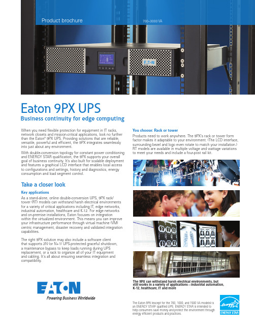
The Eaton 9PX (except for the 700, 1000, and 1500 VA models) is an ENERGY STAR qualified UPS. ENERGY STAR is intended to help consumers save money and protect the environment through energy efficient products and practices.When you need flexible protection for equipment in IT racks, network closets and mission-critical applications, look no further than the Eaton ® 9PX UPS. Providing solutions that are reliable, versatile, powerful and efficient, the 9PX integrates seamlessly into just about any environment.With double-conversion topology for constant power conditioning and ENERGY STAR qualification, the 9PX supports your overall goal of business continuity. It’s also built for scalable deployment and features a graphical LCD interface that enables local access to configurations and settings, history and diagnostics, energy consumption and load segment control.Take a closer lookKey applicationsAs a stand-alone, online double-conversion UPS, 9PX rack/tower (RT) models can withstand harsh electrical environments for a variety of critical applications including IT, edge networks, industrial automation, healthcare and K-12. For edge networks and on-premise installations, Eaton focuses on integrationwithin the virtualized environment. This means you can improve your infrastructure performance through virtual machine (VM) centric management, disaster recovery and validated integration capabilities.The right 9PX solution may also include a software client that supports 2N (or N+1) UPS-protected graceful shutdown, a maintenance bypass to keep loads running during UPS replacement, or a rack to organize all of your IT equipment and cabling. It’s all about ensuring seamless integration and compatibility.You choose: Rack or towerProducts need to work anywhere. The 9PX’s rack or tower form factor makes it adaptable to your environment. (The LCD interface, surrounding bezel and logo even rotate to match your installation.) RT models are available in multiple voltage and wattage variations to meet your needs and include a four-post rail kit.Product brochure700–3000 VAEaton 9PX UPSBusiness continuity for edge computingThe 9PX can withstand harsh electrical environments, but still works in a variety of applications—industrial automation, K-12, healthcare, IT and moreIdeal for industrial control environmentsTypically used for safety considerations, the remote power off (RPO) port allows a remote, normally open or normally closed, contact to signal the UPS to cut power to all connected equipment. With RPO functionality, you must restart the UPS manually.The remote on/off (ROO) port allows you to remotely shut down the UPS and restart it automatically when the remote contact is reset. ROO functionality is well-suited for industrial automation and remote environments where systems need to control the UPS on/off state.The port can also be programmed to be a remote signal input.Power more for less and sustainable operationThe 9PX is ENERGY STAR qualified, providing up to 93 percent efficiency in online mode. This means you can reduce energy and cooling costs, while powering more IT and networking equipment. Plus, you’d be supporting greener, more cost-effective deployments.Informed power managementKnow your power consumption down to the load segment with built-in energy metering that’s accessible through the graphicalLCD menu and optional Network Card-M2. This allows you to better understand your power consumption and make informed decisions about how to manage it.The 9PX’s load segments provide the intelligent outlet level management. Among other things, you can use them to: • S et up prioritized shutdown and automated restart protocols in the event of an outage • P rogram daily or weekly schedules (often during off-hours) to reboot or shutdown equipment proactively • R emotely cycle power to critical, frozen IT equipment without deploying costly resources These capabilities come in handy in many circumstances— for instance, powering off outlets to extend runtime during apower event.Graphical LCDSpeed of deployment, configuration and troubleshooting are more critical to businesses today than ever. With the 9PX easy-to-read local menu, 13 measurements, 25 settings, 15 controlfunctionalities, six points of identification and optional password protection are available at your fingertips. The LCD also tilts 45 degrees for optimal viewing when configured in the bottom of a rack and rotates to match rack or tower installations, making local management a breeze.Extended battery lifeBatteries are one of the biggest lifecycle costs of any UPS. Our proven 30-day, three-stage ABM ® charging and monitoring technology keeps batteries cool and stretches their lifetime by up to 50 percent. In addition, the ABM cycle tests batteries proactively, giving you advanced audible and remote alerts of risks to battery health.Optional communication cardsAdding a network card allows your UPS to connect to an Ethernet network and the internet, supporting real-time monitoring and control. With the Network Card-M2, you can record event history and log data for historic trending and analysis, reboot protected devices over SNMP/web, initiate live migration of virtual machines, remotely notify and send email/SMS notifications and alarms and more. It also enables you to integrate with industry-leading virtualization platforms and perform customizable actions like automatic shutdown in the event of an extended power failure.Including a Modbus Card in your UPS is ideal when you need a way to connect industrial electronic devices on the same network. It also provides continuous, reliable and accurate network monitoring of UPSs through a building management system.2EATON 9PX USP Learn more: /9PXOutput relay portRemote power off (RPO) and remote on/off (ROO) portFor even more runtime, add an extended battery module (EBM) to your UPS“ W e have moved from an era where it was nice just to have a network to rely on, to one in which the network sustains education... So the UPS has moved from something that used to be just in the data center to something that is now an essential part of keeping sites up and running all the time. The resilience we used to have only in our data center we now have in all of our schools.”Adams 12 Five Star Schools after deploying more than 100 Eaton 9PX UPSs234567891112101Output relay portRemote power off (RPO) and remote on/off (ROO) port External battery module (EBM) detection portNetwork Card-M2 (optional)EBM connectorRS-232 serial communication port (cable included)USB port (cable included)(2) 5-20R and (1) L5-20Rmanaged outlets (primary group)(2) 5-20R managed outlets (load segment group 1) (2) 5-20R managed outlets (load segment group 2)Ground bonding screw5-20P input cord (8-feet long)Model 9PX2000RT23456789111210Model 9PX2200GRT and 9PX3000GRT13123456789111210Model 9PX3000RT1313131Rear panel overviewOutput relay portRemote power off (RPO) and remote on/off (ROO) port External battery module (EBM) detection portNetwork Card-M2 (optional)EBM connector12Output relay portRemote power off (RPO) and remote on/off (ROO) port External battery module (EBM) detection portNetwork Card-M2 (optional)EBM connector12RS-232 serial communication port (cable included)USB port (cable included)(1) C19 outlet(4) C13 managed outlets(primary group)67RS-232 serial communication port (cable included)USB port (cable included)(2) 5-20R and (1) L5-30Rmanaged outlets (primary group)(2) 5-20R managed outlets (load segment group 1)6(1) C19 and (2) C13 managed outlets (load segment group 1)(2) C13 managed outlets (load segment group 2)Ground bonding screw C20/L6-20P input connection(detachable L6-20P to C19 input cord is 6-feet long)1011(2) 5-20R managed outlets (load segment group 2)Ground bonding screw L5-30P input cord (8 feet long)AC output branch protector10Intelligent Power Manager SoftwareBy incorporating Eaton’s Intelligent Power Manager (IPM) software, you get the tools needed to monitor and manage power equipment in your physical and virtual environments, keeping IT devices up and running during a power or environmental event. Best integrated when combined with the Network Card-M2, IPM enables you to:• E nsure system uptime and data integrity by remotely monitoring, managing and controlling devices on your network from a web-based interface • I ntegrate seamlessly with several virtualization platforms, such as VMware’s vRealize Operations Manager and vCenter dashboard, Citrix ® XenServer, Microsoft SCOM, Red Hat ® and other Xen ® open source platforms • A utomate load shedding, power capping and failover to a disaster site• A chieve the same amount of runtime with fewer batteries using load sheddingLearn more at/intelligentpower.PredictPulseremote monitoringFor remote, edge networks where deployments remain mission-critical, monitoring and service coordination can quickly become a burden. PredictPulse™ remote monitoring service provides a second set of expert eyes to keep tabs on your equipment 24/7. When a critical alert occurs, Eaton calls you.PredictPulse collects and analyzesdata from connected power infrastructure devices, providing Eaton with theinsight needed to make recommendations and take action on your behalf. For you this means:• I ncreased peace of mind and improved reliability • L ower risk of downtime by using real-time data to spot troubling trends early • F aster repairs by equipping technicians with timely, detailed insights • E nhanced focus on strategic initiatives by avoiding thedistraction of manual monitoring PredictPulse is available as a stand-alone service or a complement to an Eaton service plan.Learn more at/PredictPulse.3EATON 9PX UPS Learn more: /9PXFor additional rear panel views, please visit /9PX.9PX model selection guideThe 9PX comes as a stand-alone UPS or as part of a network bundle for easy configuration and deployment. For complete specifications, including interactive battery runtime graphs, visit /9PX.9PX – 120/110/100V 1 RT models Catalog number Description Rating (VA/Watts)Input 2Output Dimensions (HxWxD, in.)Weight (lb.)9PX700RT 9PX 700 120V RT 700/6305-15P (8) 5-15R 3.4 (2U) x 17.3 x 17.736.49PX1000RT 9PX 1000 120V RT 1000/9005-15P (8) 5-15R 3.4 (2U) x 17.3 x 17.736.49PX1500RT 9PX 1500 120V RT 1500/13505-15P (8) 5-15R 3.4 (2U) x 17.3 x 17.742.59PX1500RTN 9PX 1500 120V RTw/Network Card-M21500/13505-15P (8) 5-15R3.4 (2U) x 17.3 x 17.742.59PX2000RT 9PX 2000 120V RT 2000/18005-20P (6) 5-20R, (1) L5-20R 3.4 (2U) x 17.3 x 23.861.59PX2000RTN 9PX 2000 120V RTw/Network Card-M22000/18005-20P (6) 5-20R, (1) L5-20R 3.4 (2U) x 17.3 x 23.861.59PX3000RT 9PX 3000 120V RT 3000/2700L5-30P (6) 5-20R, (1) L5-30R 3.4 (2U) x 17.3 x 23.863.19PX3000RTN 9PX 3000 120V RTw/Network Card-M23000/2700L5-30P(6) 5-20R, (1) L5-30R3.4 (2U) x 17.3 x 23.863.11. Model voltages: 120V, 110V (20% output derating), 100V (20% output derating). The default nominal voltage is 120V.2. Input linecords are 8-feet long.9PX – 208/230/240V 3 RT models Catalog number Description Rating (VA/Watts)Input 4Output Dimensions (HxWxD, in.)Weight (lb.)9PX1000GRT 9PX 1000G 208V RT 1000/900C14(8) C13 3.4 (2U) x 17.3 x 17.738.69PX1500GRT 9PX 1500G 208V RT 1500/1350C14(8) C133.4 (2U) x 17.3 x 17.741.49PX2200GRT 9PX 2000G 208V RT 2200/2000C20 / L6-20P 5(8) C13, (2) C19 3.4 (2U) x 17.3 x 23.860.49PX3000GRT 9PX 3000G 208V RT 3000/30003C20 / L6-20P 5(8) C13, (2) C193.4 (2U) x 17.3 x 23.860.49PX3000GLRT 9PX 3000GL 208V RT 3000/30003C20 / L6-20P 5(1) L6-30R, (2) L6-20R 3.4 (2U) x 17.3 x 23.860.49PX3K3UN 9PX 3000 3U 208V RTw/Network Card-M23000/3000Terminal Block with L6-30P (2) L6-30R, (2) L6-20R 5.1 (3U) x 17.3 x 28.41063. 2U Global model voltages: 240V, 230V, 220V, 208V (derated to 2700 watts), 200V (derated to 2700 watts). The default nominal voltage is 208V.4. Detachable L6-20P to C19 input linecords are 6-feet long.5. Output wattages derated at 200V and 208V.9PX – 208/240V to 120/240V 6 RT bundles Catalog number Description Rating (VA/Watts)Input 7OutputDimensions (HxWxD, in.)Weight (lb.)9PX3K3UNTF59PX 3000 3U 208V RT UPS and 5 kVATransformer w/Network Card-M23000/3000Terminal Block with L6-30P (2) L6-20R, (1) L6-30R, (18) 5-20R10.2 (6U) x 17.3 x 28.42019PX3K3UNP19PX 3000 3U 208V RT UPS andPPDM1 w/Network Card-M23000/3000L6-30P (1) L14-30R, (1) L6-30R, (6) 5-20R 10.2 (6U) x 17.3 x 28.42039PX3K3UNP29PX 3000 3U 208V RT UPS andPPDM2 w/Network Card-M23000/3000Hardwired Hardwired10.2 (6U) x 17.3 x 28.42016. For more information on transformers and PPDMs, see the 9PX 5-6 kVA specifications at /9PX .7. L6-30P input cords are 6-feet long.9PX options Catalog number DescriptionDimensions (HxWxD, in.)Weight (lb.)9PXEBM36RT Extended battery module for 9PX1000RT, 9PX700RT3.4 (2U) x 17.3 x 17.748.19PXEBM48RT Extended battery module for 9PX1500RT, 9PX1500RTN, 9PX1500GRT, 9PX1000GRT 3.4 (2U) x 17.3 x 17.759.19PXEBM72RT Extended battery module for 9PX 2-3 kVA 2U UPS (excludes 9PX3K3UN models) 3.4 (2U) x 17.3 x 23.886.49PXEBM180RT Extended battery module for 9PX3K3UN models 5.1 (3U) x 17.3 x 25.4150Network-M2Network Card-M2 Web/SNMPFits in option slot on rear panel–Mounting hardware (all models include 4-post rail kits)Catalog number Description Dimensions (HxWxD, in.)Weight (lb.)RK2PC 2-post rack mounting rail kit (one kit required for each UPS and EBM)Fits 2-post racks 5BINTSYS Battery integration system – vertical mounting platform with wheels 7.9 x 20.5 x 31.530Power distribution (PDU) and maintenance bypass (MBP) options Catalog number Description Input Output Dimensions (HxWxD, in.)EHBPL1500R-PDU1U HotSwap MBP for use with 700-1500 VA 9PX models 5-15P (6) 5-15R 2.1 (2U) x 17.3 x 3.8EHBPL2000R-PDU1U HotSwap MBP for use with 9PX2000RT 5-20P (6) 5-20R 2.1 (2U) x 17.3 x 3.8EHBPL3000R-PDU1U HotSwap MBP for use with 9PX3000RT L5-30P(5) 5-20R 2.1 (2U) x 17.3 x 3.8ePBZ74Basic 2 kVA, 120V, 0U ePDU 5-20P / L5-20P (14) 5-20R 24 (0U) x 1.5 x 1.5ePBZ78Basic 3 kVA, 120V, 0U ePDU L5-30P (20) 5-20R1.7 (1U) x 17 x 5.1ePBZ88Basic 2-3 kVA, 208V, 0U ePDU C20(10) C13, (2) C19 1.7 (1U) x 19 x2.4ePBZ93Basic 3 kVA, 208V, 0U ePDU L6-20P (20) C13, (4) C1935 (0U) x 1.9 x 2.4ePBZ79Basic 3-6 kVA, 208V, 1U ePDUL6-30P (16) C13, (4) C19 1.7 (1U) x 17 x 5.1For additional Eaton PDU options, please visit /RackPDUSelectorEaton, ABM, Intelligent Power Manager and PredictPulse are registered trademarks. All other trademarks are property of their respective owners.Eaton1000 Eaton Boulevard Cleveland, OH 44122United States © 2020 EatonAll Rights Reserved Printed in USAPublication No.BR153063EN / GG May 2020ENERGY STAR and the ENERGY STAR mark are registered U.S. marks. ENERGY STAR is a registered mark owned by the U.S. government.Follow us on social media to get the latest product and support information.。
山东省济南市育秀中学2023-2024学年上学期九年级月考(10月)英语卷

济南育秀中学九年级上学期阶段性测试英语试题(2023.10)本试卷共10页,满分150分。
考试用时120分钟。
注意事项:1.答卷前,考生务必将自己的姓名、准考证号、座号等填写在答题卡和试卷指定位置上。
2.回答选择题时,选出每小题答案后,用2B铅笔把答题卡上对应题目的答案标号涂黑。
如需改动,用橡皮擦干净后,再选涂其他答案标号。
回答非选择题时,用0.5mm黑色签字笔将答案写在答题卡上。
写在本试卷上无效。
一、听力测试(共20小题;每小题1.5分,满分30分)略二、完形填空阅读短文,从每题 A 、B 、C 、D 四个选项中,选出一个能填入文章中相应空白处的最佳答案。
(15分)It happened years ago . When my daughter was in primary school , she brought home four small twigs(嫩枝)21 school to plant . None of them looked very hardy (耐寒的), but with hope for the future , I 22 them carefully with my daughter somewhere in our backyard that had enough 23 when it is fine . Over the years , because of the poor soil (土壤) three of them 24 .Only one survived (幸存).The tree grew crooked(弯弯曲的)and very slowly . It looked like a fat bush (灌木丛)more than a tree . Later , I noticed that it was starting to die . The 25 branches were becoming yellow and bare . Only the top third of the tree was still26 and thick . I got some help from one of my friends who was a farmer. I did mybest to save it by 27 it a lot of fertilizer(肥料), but it didn ' t work .Later one morning , I went out and looked at it again . I was wondering whether it would be better to 28 . It would make the yard look cleaner . As I walked over to take a 29 look at it , I noticed something moving within the leaves , it was a robin(知更鸟) 30 building a nest in the topmost branches (树枝). I smiled whenI looked at it . I thought maybe this old 31 was still useful . In my eyes , 32it might not be really healthy or pretty , it was still giving a bird a home . That ' s enough for it.This tree 33 me that all of our lives have a purpose . It doesn ' t matter if we are young and 34 or old and sick . We can help to make this world a better place .Until our last breath , 35 have things to do , love to give , and joy to share .Maybe that ' s the true meaning of a life .21.A.for B.to C.from D.at22.A.planted B.brought C. carried D.dropped23.A.sunlight B.water C.rain D.wind24.A. grew B.died C.changed D.remained25.A.younger B.higher C.older D.lower26.A.yellow B.green C.red D.white27.A.buying B.passing C.feeding D.bringing28.A.give it out B.pick it up C.cut it down D.put it away29.A.slow B.far C.fast D.close30.A.patiently B.carelessly C.loudly D.properly31.A.bush B.branch C.yard D.tree32.A.since B. and C.although D.so33.A.advised B. reminded C.allowed D.encouraged34.A.strong B. weak C.pretty D.ugly35.A.they B. it C.you D.we三.补全对话阅读对话,从每题 A 、B 、C 、D 四个选项中,选出一个最佳答案完成对话。
充电电池的基本测试要求

EN61960:2004
5.3 Marking 标识
EN61951-2:2003
7.1Charging procedure for test purposes 充电测试流程
Unless otherwise stated in this standard, the charging procedure for test purposes shall be carried out in an ambient temperature of 20℃±5℃ at a constant current of 0.1ItA for 16h(It A=CnAh/1h) 除非本标准特殊说明,充电程序是在20℃±5℃环境温度和0.1ItA的恒电流下充 电16h. Prior to charging, the cell shall have been discharged in an ambient temperature of 20℃±5℃, at a constant current of 0.2ItA down to a final voltage of 1.0V 充电前,电池在20℃±5℃环境温度下且在0.2ItA的恒电流下已放电到终止电压 为1.0V
Rechargeable battery basic test requirement 充电电池的基本测试要求
Contents:
-ANSI C18.2M PART1: American national standard for portable rechargeable cells and batteries-General specifications 第一部分:便携式充电电池的美国标准-一般要求 -EN61951-2:2003 Secondary cells and batteries containing alkaline or other non-acid electrolytes-Portable sealed rechargeable single cells Part2:Nickel-metal hydride 含碱性或其他非酸性电解质的二次电池和蓄电池.便携密封可再充电单电池 第2部分_镍氢电池. -EN61960:2004 Secondary cells and batteries containing alkaline or other non-acid electrolytesSecondary lithium cells and batteries for portable applications 装有碱性或其它非酸性电解液的蓄电池和电池组用于便携式的充电锂电池和电池组
艾顿能源清晰技术说明书

This new future will see data centres make valuablefinancial gains with no loss of control or productivity. And it could help all of us move to a greener energy grid, adding a valuable new component to an organisation’s Corporate Social Responsibility activities. Very importantly, making this change will not compromise an asset owner’s primary functions, energy availability or the ability to protect critical loads. The asset owner remains in complete control.Figure 1: Evolution of the energy systemEnergy has been a commodity and treated as a waste after first use Sectors (energy, transport, industry, buildings) were viewed in isolationStoring and using energy whenhaving highest value , or to provide services, turns energy into an asset Energy Storages providing flexibility to systemGrid responsive buildingsleveraging smart assets to enable low-carbon energy system based on renewablesEverything-as-a-grid concept for affordable low-carbon energy systemPresent:Future:Supporting the grid can generate revenuesParticipating in frequency regulation not only supports the introduction of new renewables, but UPS owners are paid for their availability. New markets are opening all around Europe every year.T able 1: Market value for frequency regulation in selected countries (per 1 MW per year)Nordics 1Ireland 2United Kingdom 3Germany 3Netherlands3p e r M W p e r y e a r€20 000 €40 000 €60 000 €80 000 €100 000 €120 000 €140 000 €160 000 €1 Estimated based on 2020 market value in Finland 2Actualized 2019 compensation (DS3)3Requires an additional battery investment of between 200 k€ to 500 k€2EATON EnergyAware Brochure July 2021Corporate Social ResponsibilityHave an impact on solving the world’s most urgent environmental issues More reliable power gridOffset the impact of increased renewables to energy system reliabilityMore revenueGenerate revenue from a necessary investmentIncreased competitivenessFaster deployment for new customersWhat is Eaton EnergyAware?An Eaton EnergyAware UPS leverages the stored energy within the batteries for demand response and ancillary services, positively impacting green values and supporting the environment and wider use of renewable energy. This creates savings and additional revenue – all of which increases a data centre’s competitiveness. The system is operated in a fail-safe and controlled way, using storedenergy in parallel with mains and keeping enough energy to meet back-up time requirements and always prioritising critical load protection.The Eaton EnergyAware UPS3EATON EnergyAware Brochure July 2021Energy AwareFigure 2: Global electricity generation mix (Bloomberg)The worldwide move away from fossil fuels is driven by affordable renewable energy, legally binding agreements and increasingly vocal public demand to reduce greenhouse gas emissions.By 2050, it is estimated that nearly 50% of the world’s electrical energy will come, from variable wind and solar (Bloomberg). In Europe, renewables will exceed 50% of electrical energy by 2030 (Ember).It is expected that the cost of fossil fuels will rise as scarcity increases, with a fall in mass-scale coal and gas production affecting the economy of scale for such energy. Over the next decade it is expected that wind and solar power will be cheaper to produce than power from any average gas or coal plant in Europe.20190%10%20%30%40%50%60%70%80%90%100%197019801990200020102020203020402050Historical global power generation mixNEO 2020 global power generation mix56% solar & wind 24% fossil fuels by 205069%renewables4EATON EnergyAware Brochure July 2021The transition will be made easier in terms of cost and reliability of supply if a more flexible and open energy system is brought on stream, involving both new energy providers and more localised grid structures.Data centres and energy useData centres are major energy consumers and their consumption is expected to grow in the coming years as the use of digital services and number of users grows. Eaton estimates the global power capacity of the world’s data centres is 47.5 GW today. This is equivalent to 125% of the total power used by a country the size of the UK.Data centres are well positioned to play their part in the energy system. They need a constant, steady flow of energy at all times – downtime is not an option. As a result, significantresources are put into technologies like Uninterruptable Power Supplies which regulate energy throughput and battery-based backup which can come on stream within milliseconds if external energy supplies are compromised.5EATON EnergyAware Brochure July 2021S U S T A I N A B I L I TY SMA RT E NER GYT C OA V A I L AB I L I T YA D D IT IO N A L R E V E N U Ewaiting to be harnessed.LoadR e s e r v eTaking a new roleThe transition from fossil to renewable energy is inevitable. This presents new challenges for grid operators to balance supply and demand, and to manage disturbances and grid reliability. Data centres can become contributors in the new energy market without any loss of autonomy or control, while helping to green the grid and maintain grid stability. This all leads to a more stable grid and lower electricity prices.Intelligence withinMuch of what data centres need to make the transition is already in place. The core resources of transformer, battery bank, and switchgear, all necessary for meeting their own needs, do not need to change.A DC electrical system vs. a Battery Energy Storage System (BESS)Commonalities between Data Centre andBESS power system(1H. Rubel, C. Pieper, Z. Jan and Y. Sunak, “How batteries and solar power are disrupting electricity markets,” BCG, Boston, 2017.7EATON EnergyAware Brochure July 2021How muchrevenue can an EnergyAware UPS generate?Eaton estimates typical returns of up to 100 000 € per year for each MW of power allocated to grid support to help energy providers balance energy demands. Actual amounts will vary depending on variables such as battery capacity and how frequently grid contributions are made.The primary function of an EnergyAware UPS is to meet the data centre’s energy needs. This includes provisioning the data centre if the grid goes down. Additional capacity, not required by the data centre, can be used to support the grid.An EnergyAware UPS can be installed as an upgrade to existing systems with a minimal investment.Eaton has completed successful pilot projects in Scandinavia and Ireland. The first commercial data centre installation was deployed in Finland in 2019.Does contributing to the grid compromise a data centre’s uptime?Is it complex to install and maintain an EnergyAware UPS?Are there proven examples of an EnergyAware UPS supporting the grid?Frequently Asked QuestionsWe are already seeing restrictions on where data centres can exist due to the availability of energy. To give one example, until just recently Amsterdam banned new data centres because the grid could no longer support them. If data centres contribute to the grid, they can avoid this type of exclusion, and make location decisions based on other relevant factors.Energy markets and ancillary services are constantly developing and new reserve types and opportunities for consumers are opening. To gain from these future opportunities, it’s important to choose technologies today that can support these types of activities. This allows fast deployment to new opportunities without major changes to the system design or significant additional investments.8EATON EnergyAware Brochure July 2021How data centres contribute todayThese examples show how data centres already contribute to local grids and how they are paving the way withinnovative use of technology.Providing power at times of needDuring 2018, Statnett, a Norwegian Transmission System Operator, and Fortum, a leading energy provider inthe Nordic and Baltic countries, trialled a Fast Frequency Response during normal system operation. Norwegiandata centre operator Basefarm was one of the participants. Performance requirements for Fast FrequencyResponse in the pilot were 49.6 Hz activation frequency and providing a full response within two seconds for amaximum duration of 30 seconds. During the pilot a power plant failure in Finland caused instability in the grid,and the UPSs were tested for real. The data centre reserves were the quickest to activate – faster than hydro,industrial consumption and electric vehicles – and providing the desired power impact in far less than the twoseconds required.Contributing to the gridEaton launched the first commercial application of its frequency response solution, based on Eaton UPSs, aftera successful pilot at its European headquarters in Ireland in 2019. Eaton partnered with Enel X, a global energy management company to bring the solution to market.The solution enables organizations to take part in Irish grid operator EirGrid’s DS3 system services, whichsupports renewable integration through the management of grid frequency.The proof of concept pilot with Enel X and EirGrid has demonstrated how the EnergyAware UPS managescritical loads and mission critical applications, and improves grid stabilization. It will also generate income.The first commercial deployment of EnergyAware UPS took place in 2019, when Aurora DC in Finland deployed its 400-kW capacity system into the Nordics FCR-N market. The goal was to build a reliable and safe data centre using cutting-edge, modern technology in a sustainable way. The system consists of two Eaton 93PM 200 kW UPS’s together with lithium-ion batteries sized for 60 minutes of runtime. Aurora DC’s facility in Finland became the first data centre to procure 100% green energy while simultaneously supporting the introduction of new renewables into the grid.9EATON EnergyAware Brochure July 2021option, but a necessity. In this transition period much is in flux. Data centre development is already being banned in some locations.Yet data centres are well equipped to become part of the solution as we move away from fossil fuels towards renewables. If they grasp this challenge, they will proveSupport grids to adapt more renewable power and replaces reserves based on fossil fuelsgridOffset the impact of increased renewables to the system reliability Data centres can benefit from the EnergyAware technology in multiple ways - whether you need energy optimization or you want to participate in grid support.Ancillary ServicesPeak Shaving:limit maximum load to the grid and save on the energy tariffPaid for availabilityTime-of-Use:buy energy when it expensiveFrequency Regulation:support the grid to avoid outages and bottle necks10EATON EnergyAware Brochure July 2021Case study: 10 MW data centre in Ireland* The selected activation frequency is 49.8 Hz** Based on VRLA batteries. Can be done with either VRLA or Lithium-ion batteriesThis case study uses real market values from 2019 in a hypothetical scenario for a 10 MW data centre in Ireland. The UPS capacity is: 10 MW and the battery capacity is: 10 minutes (5 minutes for the load + 5 minutes for EnergyAware). The typical Total Cost of Ownership (TCO) life cycle is: 10 years.UPS capacity:10 MWTCO lifecycle:10 yearsBattery capacity:10 minutesPayback time:1 year11EATON EnergyAware Brochure July 2021Changes to the products, to the information contained in thisdocument, and to prices are reserved; so are errors and omissions. Only order confirmations and technical documentation by Eaton is binding. Photos and pictures also do not warrant a specific layout or functionality. Their use in whatever form is subject to prior approval by Eaton. The same applies to Trademarks (especially Eaton, Moeller, and Cutler-Hammer). The Terms and Conditions of Eaton apply, as referenced on Eaton Internet pages and Eaton order confirmations.Follow us on social media to get thelatest product and support information.EatonEMEA Headquarters Route de la Longeraie 71110 Morges, Switzerland Eaton.eu© 2021 EatonAll Rights ReservedPublication No. BR153151EN July 2021Eaton is a registered trademark.All other trademarks are property of their respective owners.。
406DUO充电器中文说明书

406DUO 使用说明书( V1.2.0 )目录使用须知 ................................................................................................................................................................. - 4 - ● 安全须知........................................................................................................................................................... - 4 - ● 版权声明........................................................................................................................................................... - 4 - ● 406DUO性能特点......................................................................................................................................... - 5 - ● 外观参数........................................................................................................................................................... - 5 - ● 电性能参数....................................................................................................................................................... - 5 - 设备简介 ................................................................................................................................................................. - 6 - ● 406DUO部件、接口名称............................................................................................................................. - 6 - ● 406DUO按键功能、界面图标 ..................................................................................................................... - 6 - ● 406DUO标准配件......................................................................................................................................... - 8 - ● 406DUO选购配件......................................................................................................................................... - 8 - 充电器的连线 ......................................................................................................................................................... - 9 - ● 电源输入地线不能与输出地线连通............................................................................................................... - 9 - ● 接线顺序........................................................................................................................................................... - 9 - ● 双通道的连线方式........................................................................................................................................... - 9 - ◆ 通道异步模式连线方式 ............................................................................................................................... - 9 - ◆ 通道同步模式连线方式 ............................................................................................................................... - 9 - 充电器充放电程序设置及使用 ........................................................................................................................... - 10 - ● 电源设置......................................................................................................................................................... - 10 - ● 程序添加与管理............................................................................................................................................. - 11 - ● 运行充电器程序............................................................................................................................................. - 11 - ● 程序运行状态................................................................................................................................................. - 12 - ● 错误提示......................................................................................................................................................... - 13 - ● 程序编辑......................................................................................................................................................... - 13 - ◆ LiPo/LiIo/LiFe电池的充放电设置.......................................................................................................... - 14 -❑ LiPo/LiIo/LiFe电池充电设置 ............................................................................................................ - 14 - LiPo/LiIo/LiFe电池的非平衡充电 .............................................................................................. - 15 - LiPo/LiIo/LiFe电池的平衡充电 .................................................................................................. - 15 - LiPo/LiIo/LiFe电池充电Advanced设置 .................................................................................... - 16 - LiPo/LiIo/LiFe电池充电SAFETY设置 ..................................................................................... - 16 - ❑ LiPo/LiIo/LiFe电池储存模式设置 .................................................................................................... - 17 - ❑ LiPo/LiIo/LiFe电池放电设置 ............................................................................................................ - 17 - To channel模式设置 ..................................................................................................................... - 17 - LiPo/LiIo/LiFe电池放电Advanced设置 .................................................................................... - 18 - LiPo/LiIo/LiFe电池放电Safety设置 .......................................................................................... - 18 - ❑ LiPo/LiIo/LiFe电池循环充放电设置 ................................................................................................ - 18 - ❑ LiPo/LiIo/LiFe电池执行平衡功能 .................................................................................................... - 18 - ◆ NiMH/NiCd电池的充放电设置 .............................................................................................................. - 19 -❑ NiMH/NiCd电池充电设置................................................................................................................. - 19 - NiMH/NiCd电池充电Advanced设置 ........................................................................................ - 19 - NiMH/NiCd电池充电Safety设置 .............................................................................................. - 19 -❑ NiMH/NiCd电池放电设置................................................................................................................. - 20 - NiMH/NiCd电池放电Safety设置 .............................................................................................. - 20 - ❑ NiMH/NiCd电池循环充放电设置..................................................................................................... - 20 - ◆ Pb电池的充放电设置 .............................................................................................................................. - 20 -❑ Pb电池充电设置 ................................................................................................................................ - 20 - Pb电池充电Advanced设置 ........................................................................................................ - 21 - Pb电池充电Safety设置 .............................................................................................................. - 21 - ❑ Pb电池电池放电设置......................................................................................................................... - 21 - ❑ Pb电池循环充放电设置..................................................................................................................... - 21 - ◆ NiZn电池的充放电设置.......................................................................................................................... - 21 -❑ NiZn电池充电设置 ............................................................................................................................ - 21 - NiZn电池的非平衡充电 .............................................................................................................. - 22 - NiZn电池的平衡充电 .................................................................................................................. - 22 - NiZn电池充电Advanced设置 .................................................................................................... - 22 - NiZn充电SAFETY设置 ............................................................................................................. - 22 - ❑ NiZn电池放电设置 ............................................................................................................................ - 22 - To channel模式设置 ..................................................................................................................... - 22 - NiZn电池放电Advanced设置 .................................................................................................... - 22 - NiZn电池放电Safety设置 .......................................................................................................... - 22 - ❑ NiZn电池循环充放电设置 ................................................................................................................ - 22 - 406DUO参数设置 ............................................................................................................................................... - 23 - ● 406DUO参数设置....................................................................................................................................... - 23 - ◆ Charger Setup ............................................................................................................................................ - 23 -❑ 温度&风扇设置..................................................................................................................................... - 23 - ❑ 提示音设置............................................................................................................................................ - 24 - ❑ LCD设置............................................................................................................................................. - 24 - ❑ 输出功率设置........................................................................................................................................ - 24 - ❑ 电源设置................................................................................................................................................ - 25 - ❑ 保存&加载配置文件设置..................................................................................................................... - 25 - ❑ 通信方式................................................................................................................................................ - 26 - ❑ 语言设置................................................................................................................................................ - 26 - ❑ 设备校准................................................................................................................................................ - 27 - ◆ Extra Function ........................................................................................................................................... - 28 -❑ 日志文件管理........................................................................................................................................ - 28 - ❑ 伺服器测试............................................................................................................................................ - 28 - ❑ 脉冲测试................................................................................................................................................ - 29 - ● USB & SD卡的使用.................................................................................................................................... - 30 - ● 保修及服务..................................................................................................................................................... - 30 - 406DUO固件升级 ............................................................................................................................................... - 31 - ● 通过USB接口更新固件 ............................................................................................................................... - 31 - ● 通过SD卡更新固件...................................................................................................................................... - 32 - 406DUO接入LogView ....................................................................................................................................... - 33 - ● LogView的使用步骤................................................................................................................................... - 33 - 重要提示 ............................................................................................................................................................... - 35 - ● 反射充电模式的充电原理............................................................................................................................. - 35 -● 电源回充模式................................................................................................................................................. - 35 - ● 通道再生模式................................................................................................................................................. - 35 - ◆ Resistance or bulbs .................................................................................................................................... - 35 - ◆ Charging battery ........................................................................................................................................ - 36 - ● 锂电池外部扩展放电模式............................................................................................................................. - 36 - 附录....................................................................................................................................................................... - 37 - ● 通道运行状态指示......................................................................................................................................... - 37 - ● 通道控制状态指示......................................................................................................................................... - 37 - ● 错误指示......................................................................................................................................................... - 37 -使用须知●安全须知使用充电器前,请认真阅读本章节内容;以便于您更放心、更安全的使用充电器。
博戈特工程TM-2030三态电池监测仪操作和用户手册说明书

DAYS SINCE "CHARGED"................RESET: to 0 days
DAYS SINCE EQUALIZED................RESET: to 0 days
=AMPS or
=WATTS
REPLACED PERCENTAGE FROM LAST DISCHARGE
Revised 04/10/2018
Bogart Engineering 2018
TriMetric Installation
C H
B D
A
Illustra on By R. Brucker; Used with Permission
E
Negative wires from all loads and charging sources must connect to the load side of the shunt: ‐Inverter ‐Charge Controller ‐Alternator ‐Chassis Ground
our complete warranty policy at /support
Please contact us directly before attempting to return any product for repair or replacement.
Basic Programmable Parameters required to properly use the TriMetric The values described below are default values. Please contact your battery manufacturer for recommended charging information. P1: Charged voltage set point: The battery is signaled as “charged” when volts exceeds the P1 value, and charging current is less than as described in P2 (below). P1 is also the “absorb voltage” set point for the SC-2030 charger when used. The default value for a 12 volt system is “14.3”
PowerPlex

BROCHUREOVERVIEW OF PowerPlex®The electrical system of a yacht is the lifeline to her operation. Why risk it with outdated technologies and methodologies that are sus-ceptible to corrosion and failure? Options exist, and with digital switching technology, you can improve the reliability and safety of your customer’s yachting experience.All with the touch of a button.Unlike traditional power distribution systems with mechanical circuit breakers and switches, a digital switching system allows you to monitor and control the electrical operations of a yacht using an intelligent interface. Touch screens and other smart devices can be programmed and customized to the needs of the yacht owner. And once installed, digital switching systems can be easily enhanced and upgraded.Your customers already expect it from their phones, homes, and cars. Why should their yachts be any different? Streamline vessel intelli-gence and enhance their yachting experience with digital switching.THE USER EXPERIENCEMEETS THE MODERN WORLDGain the Control and Convenience of a Digital Switching System with PowerPlex®Leading boatbuilders and yacht manufacturers choose PowerPlex®. Why? PowerPlex® is a fully integrated alternative to traditional onboard power distribution and electrical systems. Our software and hardware components provide a modular digital switching solution creating an easy-to-use, customizable, intuitive system for your company’s yachts.With PowerPlex®, your yachts’ internal systems can be monitored from the helm, in the salon, or on-shore via a smartphone, tablet or PC. Yacht owners and captains can view vital systems including tanks, pumps, motors, and battery levels. With a single touch, you can switch off lights and turn on the air conditioning via programmable sequences. Control everything at the same time with a personalized interface specific to your customer.PowerPlex® provides your company with a flexible platform for creating customized electrical networks and limitless control. Discover themodern way of electrical installation with PowerPlex®.LET’S FACE IT; THE OCEAN IS A BIG PLACE.YOU NEED SAFE AND RELIABLE OPERATIONS.Your brand is built on reputation, and an electrical or system failure at sea is a quick way to ruin the customer experience. With Power-Plex®, your customers receive an onboard system which combines safety and reliability. Our network connects, regulates, controls, and monitors a wide variety of loads – quickly, securely, and – if needed – automatically. These operations may include navigation systems, engines, bilge/ballast tanks, cargo control systems, and more.Specialized safety management functions monitor and alert the crew of any malfunctions of the electrical system. DC and AC electrical loads, energy usage, tanks, and pumps are continuously monitored.Warnings, such as if a bilge or freshwater tank triggers an alarm, are displayed in a list and can be used to trigger pop-ups. A history of the alarms from the last 30 days, with a limit of 100 entries per day, is available to keep track of all failures. EXPERIENCE TOUCHSCREEN SATISFACTIONE-T-A’s PowerPlex® Touch Panels are cost-effective displays providing state-of-the-art accessibility and monitoring of the onboard elec-trical systems. They enhance communication and configuration possibilities of PowerPlex® and can completely replace conventional panels and traditional switches.Relevant system data of electrical loads, sensors, and operational statuses are processed and displayed on the customer-specific touchscreen in real time. The ON/OFF operation for all connected loads is monitored allowing users to proactively address issues as they occur.The PowerPlex® Touch Panel is available in a 12” model. Incorporating the PowerPlex® Webserver will help you save space on the helm by allowing you to control and monitor your yacht on a multi-function display (MFD), mobile phone, tablet or PC.GET A CUSTOMIZED USER EXPERIENCEWITH PowerPlex® SUITE SOFTWAREThanks to the PowerPlex® Suite software, you can design a customized interface to suit your customers’ needs without programming know-how. Our user-friendly software is easily configured and integrated. You can define switching and lighting scenarios, monitoring, diagnostics, and alarm indication schemes, and assign a unique identifier to each of the intelligent communication components in the system.The complete electrical onboard system can also be configured to operate in a pre-determined way using the scenario-functions such as night mode or cruising mode. Or, you can combine and switch several loads simultaneously using just one button.Design your ideal interface from various switches and touch screen displays and integrate your smartphone and tablet for a custom user experience. The PowerPlex® Suite helps you create the personalized user experience your customers now expect from technology. OUR MODULAR DESIGNSAVES TIME AND MONEYToggles, push button switches, and costly wiring installations are things of the past. Our modular design simplifies electrical installation, reduces cabling, and significantly increases functionality. This all adds up to a lighter vessel with faster time-to-delivery to the customer. Yacht captains like the convenience of managing their boat’s systems through an intuitive interface. Yacht owners like the ability to “future-proof” their boats to take advantage of new products and technology. And Yacht manufacturers like the ease-of-installation and improved marketability. PowerPlex® delivers on all of the above.AN ELEGANT INFRASTRUCTUREBUILT TO LASTThe backbone of the PowerPlex® System is the CAN bus architecture. PowerPlex® modules communicate with each other over two-wire serial connections. The modules are placed where needed throughout the yacht and connected to sensors, switches, indicators, lamps, and wherever else power monitoring and control is required. Using the installation software, you can assign the inputs and outputs for each module. For example, you can program an input for a PowerPlex® module as the sensor value “Water tank level too low” and the output as the command “Water pump ON.”The loads controlled by the module are installed on the boat, but don’t need to be close to the input signal. The PowerPlex® CAN bus network infrastructure allows you to monitor and switch systems and appliances anywhere on the boat from any display. The primary com-ponents of the PowerPlex® system consist of DC Power Distribution Modules, AC Power Distribution Modules, Gateway and Webserver. The DC Power Modules have 8 digital inputs, 4 analog inputs and 8 outputs. They provide galvanic isolation of the CAN bus interface as well as redundant protective functions for connected DC loads and flyback diodes for inductive loads. These are the workhorse of the electrical system and are used to control devices that draw a lot of power. You can also add an additional layer of protection with circuit breakers if necessary.The PowerPlex® AC Module is a 14-channel power distribution unit equipped with either E-T-A single pole or double pole 8345 circuit breakers with full remote operation. With the remote circuit protection device installed, all AC loads are protected for short circuit and overload conditions and are completely remote controlled through the PowerPlex® software to allow easy on/off operation. This remote capability allows you to place the AC modules in locations with limited ac c essibility, closer to the loads for more economical wire runs. The circuit breakers are bolted into the unit for a secure connection but allow for easy changes on the fly, if a load needs to be added or re-placed suddenly. Each circuit breaker also can be manually reset in the event of a failure on the bus, increasing the reliability of the system. THE GATEWAY TO IMPROVEDELECTRONIC OPERATIONAdding redundant systems to your yacht can be time consuming and expensive. Our PowerPlex® Gateway sets a new standard.The PowerPlex® Gateway is a multi-protocol module that connects PowerPlex® systems with other networks. It allows the combination of a PowerPlex® CAN bus with various other bus systems including NMEA2000, SAE J1939 and Modbus. We partner with top OEM manufac-turers including Garmin, Sea Recovery, B&G, and Dometic to ensure smooth integration with the PowerPlex® platform.Now you can connect and control a wide range of functions and electrical components within your electrical systems. Processes can be programmed to run automatically, or they can be designed to respond to specific conditions.These modules also increase the reliability of your yachts by identifying any faulty systems. The PowerPlex® Gateway can identify and isolate product failures so yacht owners and staff can expedite any needed maintenance or repairs without impacting the performance of other systems on the boat.PROTECTIONIS PRICELESSOnce installed, the PowerPlex® system becomes an integral part of the yachts’ operations. The system distributes power to all points of a boat, including lighting and heater controls, bilge pumps, water pumps, and fans.PowerPlex® collects data from all sensors and operating elements such as temperature and tank level measurement points and the on/ off status signals of actuators. It will monitor and protect all equipment against dangerous overloads and short circuits by isolating faulty loads in the system and indicating its failure. Through the power of digital programming, you can switch electronic components off and on based on pre-determined scenarios and monitor these components from anywhere on or off shore. If you forget to turn off the lights, you can do so from your tablet or smartphone.CRUISE WITH CONFIDENCE -TECHNICAL SUPPORT EVEN AT SEAIf your customers ever need support, they need a system that can reach on-shore assistance. As long as there is an internet connection, E-T-A’s worldwide service network can remotely analyze the yacht’s electrical system. This remote tele-maintenance enables troubleshoot-ing of customer-specific problems and challenges, drastically reducing downtimes, stoppages, and costs.With PowerPlex® and E-T-A, your customers gain access to an international service network, which means support is never far away. And, the reliability of our PowerPlex® product is certified by Germanischer Lloyd and Lloyd’s Register. For once, support doesn’t just fall on you.TECHNICAL SPECIFICATIONSThe modular components of PowerPlex® are designed to simplify installation and increase the flexibility in the design for each custom digital switching system.PowerPlex Power ModulePowerPlex AC ModulePowerPlex Web ServerPowerPlex Battery MonitorPowerPlex Power MeterCircuit BreakersCAN Bus CableTerminating ResistorsPowerPlex®ConfigurationSoftwareCAN-USB Converter Plus Soft-ware/RJ-45 AdapterVoltage SupplyRemote Hydraulic Magnetic Circuit BreakersOVERVIEW OF PowerPlex® COMPONENTSAll PowerPlex® components are built for a marine environment and provide the protection and reliability you need for simple to morecomplex electrical systems. The modular design of our system allows you to create a customized solution for each individual yacht.PowerPlex Battery Monitor PowerPlex Power MeterTouchscreen Panel 7’’ TP070 PowerPlex Gateway PowerPlex Web ServerPowerPlex® SUITE SOFTWAREYOUR HOMESCREENUnnecessary trips to various areas of your boat are a thing of the past. Let PowerPlex® do this for you with the practical scenarios feature. PowerPlex® can examine each electrical load and determines if and for how long it´s needed for a selected scenario. Increase the security and comfort for your customers through intelligent power distribution, control and monitoring.Example of Home Screens Showing Power Consumer LevelsENERGYMANAGEMENTElectrical equipment increases comfort on board and different energy concepts can be configured using PowerPlex®. This allows the gen-erator to start automatically when AC devices are switched on – depending on the configuration. With an existing shore connection, the generator would not be turned on by PowerPlex®.For each on-board battery, the current status will be determined and displayed. This allows load shedding of unimportant loads when pre-determined battery levels are reached, preserving the limited available battery capacity.Examples of Energy Screens Showing Battery StatisticsThe conventional switch panel can be combined with or completely replaced by PowerPlex®. All loads with DC 12 V / DC 24 V as well as AC 120/240 V / AC 230 V can be switched on or off via a touch screen. On-screen buttons provide the ON/OFF functionality of switches. Here, PowerPlex® opens up new possibilities for boat designers. Via the system configuration, it is possible to switch several loads simul-taneously using just one button.The complete electrical on-board system can also be configured to operate in a pre-determined way using the scenario-functions i.e. night mode or cruising mode.Example of Screen for Lights Example of Screen Overview Example of Screen for Loads PUMP AND TANKMANAGEMENTPowerPlex® controls and monitors the status of pumps and various tank levels with sensors. The system provides this information via the displays, alerts the crew when critical levels are reached and activates or deactivates the pumps.The monitoring function of PowerPlex® switches off the respective pump when pre-set tank levels are reached again and prevents it from idling. The status and location of the pumps and tanks are indicated on the user interface.Example of a Tank Screen Example of a Tank Screen Example of a Pump ScreenIncreased safety on-board is accomplished by using customized safety management functions.PowerPlex® monitors, informs and alerts the crew of any malfunctions within the electrical installation. For example, the bilge tank or the fresh water alarm will be clearly displayed in a list.To better see any malfunctions, up to 100 alarms per day for the past 30 days are listed in an alarm history. Warnings and other messages are displayed as pop-up´s and are also logged in the alarm history.Fusebox & Alarm List Screen Example of a Pop-Up Screen Example of a Pop-Up ScreenYour Benefits• Integration of any Windows-based Touch PCs• Individual designs of your graphical user interface (GUI)• Intuitive to understand, no programming skills required• Increased functionalityUSER EXPERIENCE:FULL CONTROL AND MONITORINGPowerPlex® HMI SolutionsIncrease your client’s experience. The PowerPlex® HMI devices allow convenient visibility and intuitive operation. Visualize status, alarm or error messages. Select your preferred HMI from various keypads, touch displays for your PowerPlex® application. The PowerPlex® Suite allows you to create your own design.PowerPlex® HMI devices for convenient control and monitoring of the entire electrical system.INTEGRATION OFTHIRD-PARTY SYSTEMSIntegrating third-party systems is crucial when building a smart boat. E-T-A has partnered with marine electronics companies to improve the user experience. PowerPlex® control and monitoring is possible at the touch of a finger on various boat locations such as the helm, salon or via mobile devices.Your Benefits• Increased convenience for your customers• Convenient control and monitoring of the electrical installation• Status control at a glance - on board or on-shore• Superior performance and high quality• Easy to installIntegration PartnersCONTACT US 1551 Bishop Court Mt. Prospect, IL 60056phone: (847) 827-7600 email:****************。
电芯配对 操作流程
电芯配对操作流程Pairing batteries is a crucial process in the production of battery packs, as it ensures the optimal performance and safety of the final product. When pairing batteries, it is essential to match cells with similar capacities, internal resistances, and ages to prevent issues such as imbalance and premature failure. This process requires careful attention to detail and precision to create a reliable and long-lasting battery pack.在生产电池组时,电芯配对是一个至关重要的过程,它确保了最终产品的最佳性能和安全性。
在配对电芯时,关键是要匹配具有相似容量、内阻和年龄的电池单体,以防止出现失衡和过早失效等问题。
这个过程需要仔细的注意细节和精准性,才能制造出可靠和耐用的电池组。
One important aspect of battery pairing is cell capacity matching, as cells with different capacities may lead to overcharging or discharging of certain cells, causing potential safety hazards. By pairing cells with similar capacities, the risk of overvoltage or overcurrent situations is minimized, ensuring the battery packoperates within safe limits. Capacity matching also helps to improve the overall performance and longevity of the battery pack.电池配对的一个重要方面是单体容量匹配,因为容量不同的电池单体可能导致某些电池过充或过放,从而造成潜在的安全隐患。
- 1、下载文档前请自行甄别文档内容的完整性,平台不提供额外的编辑、内容补充、找答案等附加服务。
- 2、"仅部分预览"的文档,不可在线预览部分如存在完整性等问题,可反馈申请退款(可完整预览的文档不适用该条件!)。
- 3、如文档侵犯您的权益,请联系客服反馈,我们会尽快为您处理(人工客服工作时间:9:00-18:30)。
How to Choose a Primary BatteryBY SOL JACOBSVICE PRESIDENT AND MANAGER OF BATTERY DIVISIONTADIRAN ELECTRONIC INDUSTRIES INC.PORT WASHINGTON, N.YThe technical press pays a lot of attention to rechargeable, or secondary batteries, mainly because of the growing number of portable-computing and communications applications. But there are categories of applications that can be addressed only by the less glamorous class of primary batteries.These applications can be organized into groups that help to rationalize the choice of primary battery technology. However, an overview of existing battery technologies is a necessary first step in the decision-making process.The types of primary battery chemistries available today include traditional zinc-carbon-ammonium chloride (Leclanche cell), zinc-carbon-zinc chloride, alkaline (the leading type for consumer use), zinc-air and a variety of lithium-based chemistries.The chemical systems employed in the most widely used primary battery types have been around for quite some time. The zinc-carbon-ammonium chloride "dry," or Leclanche cell, system is more than 75 years old and still accounts for a little less than 10 percent of all of the primary battery units sold in the United States. The zinc-carbon-zinc chloride system, a heavy-duty version of the Leclanche cell, constitutes a similar portion of U.S. primary battery consumption.By far, the leading primary battery technology, in terms of units sold in the United States, is the alkaline system, based on manganese dioxide, zinc and a caustic potassium hydroxide-zinc oxide electrolyte. Alkaline-cell technology offers greater capacity for a given cell size compared with Leclanche types, but it typically costs 50 percent more and weighs about 25 percent more.There have been some apparent improvements in alkaline cell performance in recent years, but these have been a result of changes in packaging and manufacturing techniques rather than any improvements to the basic chemical system.In the past, alkaline batteries were made with complex sealing systems and thick steel outer cases and end caps. Several years ago, a method was developed that allowed manufacturers to use thinner packaging materials and more volumetrically efficient seals. That created room for more active material within a given standard cell size and increased capacity.The next change to come in alkaline-cell technology may actually be a step backward in capacity, but for a good cause. Mercury, an environmental pollutant, is used in alkaline batteries as an anti-passivation stabilizer for the zinc electrode. Without mercury, chemical processes within the battery cause the zinc to function less efficiently as discharge proceeds because of passivation of zinc surface, thus limiting useful battery life.In the interest of keeping as much mercury out of the environment as possible, several states have developed proposals to reduce the mercury content of alkaline batteries. The current target for mercury content is 250 ppm. The European Union has developed similar rules, also with the allowable mercury content of 250 ppm.Major producers of alkaline cells are conducting research to find environmentally suitable replacements for mercury. By the time mercury is phased out, it is likely the end user will not notice any changes in alkaline battery performance.Mercury cells were once widely used in many applications that required miniature or subminiature size and relatively low drain. Now, zinc-air battery technology, originally developed in the mid-1980's, has become a high-capacity, high-energy-density replacement for mercury.Compared with mercury cells of the same physical size, zinc-air batteries, with a nominal Open Circuit Voltage (OCV) of 1.4 V, are up to 40 percent lighter and have twice the capacity. Zinc-air batteries offer much higher energy density than any alkaline battery type.Batteries using zinc-air technology are energized only when atmospheric oxygen is absorbed into the electrolyte through a gas-permeable, liquid-tight membrane. With the removal of a sealing tab, oxygen from the air is introduced into the cell. A zinc-air battery typically reaches full operating voltage within 5 seconds of being unsealed. The zinc-air system, while sealed, has excellent shelf life, with a self-discharge rate of only 2 percent per year.Coin-sized versionsZinc-air batteries are available in button sizes for direct replacement of other button types, but recently introduced coin-sized versions are designed for pagers as well as personal medical equipment, such as cardiac monitors and transmitters.Of all the primary battery chemistries, lithium has stirred the most interest among members of the electronics industry. Lithium is an ideal material for battery anodes because its intrinsic negative potential exceeds that of all metals. Lithium is also the lightest non-gaseous metal. Batteries based on lithium chemistries have the highest specific energy (energy per unit weight) and energy density (energy per unit volume) of all types. The high energy density is a result of lithium's high potential and the fact that lithium reacts strongly with water.That precludes the use of any aqueous (water-containing) electrolyte---but that turns out to be a benefit. Because the oxygen and hydrogen in water dissociate in the presence of a potential above 2 V, cells using aqueous electrolytes are limited in voltage. Lithium cells, all of which use a non-aqueous electrolyte, have nominal OCVs of between 2.7 and 3.6 V. However, the use of non-aqueous electrolytes results in those cells' having a relatively high internal impedance.Lithium batteries also have extended operating-temperature ranges, made possible by the absence of water and the chemical and physical stability of the materials. Some lithium-based systems, including Tadiran's inorganic system, can operate at temperatures as low as -55o C and as high as +150o C. While incineration or other exposure to very high temperature can cause the casings of lithium batteries to fail catastrophically, other battery types behave similarly under similar conditions.Under the broad category of primary lithium battery types, there are several chemical systems in mainstream use, each with its own set of performance and safety characteristics. They are poly (carbon monofluoride) lithium, or (CF)X-Li; manganese dioxide lithium, or MnO2Li; thionyl chloride lithium, or SOCl2Li; sulfur dioxide lithium, or SO2Li; and iodine lithium, or I2Li.Poly (carbon monofluoride) cells have an OCV of 2.8 V and moderately high energy density. Cylindrical types are manufactured with a spiral-shaped cathode and crimped elastomer seals. Though generally safe, under extreme conditions the elastomer seals can fail before the case fails, thus allowing the relatively reactive cell constituents to escape. The cells are available in all standard cylindrical sizes as well as coin types.Manganese dioxide lithium cells are also available in standard cylindrical and coin sizes. They are in many ways equivalent to poly (carbon monofluoride) cells in terms of construction, energy density, safety and OCV, but typically have only about half the service life. However, manganese dioxide-lithium cells are well-suited to applications having relatively high continuous- or pulse-current requirements, since the cell internal impedance is somewhat lower than for other types.A proprietary lithium-iodine technology is offered by some manufacturers, and that approach offers very good safety, since it uses only solid constituents. The separator in a lithium-iodine cell can "heal" itself if cracks occur. This battery type powers the majority of implanted cardiac pacemakers. The major drawback to the lithium-iodine system is its high internal impedance, which limits its use to very low-drain applications.Sulfur dioxide-lithium cells are used almost exclusively in military/aerospace applications and have somewhat lower energy density than manganese dioxide-lithium or poly (carbon monofluoride) lithium cells. Their service life and energy density are less than half that of thionyl chloride-lithium cells. For safety, and "emergency" vent structure is required in the hermetically welded case.High EnergyThionyl chloride-lithium cells have the highest energy density of all lithium types and are manufactured in welded, hermetically sealed cases. Service life is an unmatched 15 to 20 years and holds for all case types---cylindrical and coin or wafer. The cells are best suited for applications having very low continuous-current and moderate pulse-current requirements. Their extremely long service life and low self-discharge rate make them ideal where physical access is limited, such as for remote sensing systems.Lithium battery chemistries differ in several important characteristics. Carefully matching those characteristics to the conditions of a particular application is key to safe and reliable operation of the system.The critical considerations are: nominal, minimum and maximum voltage; initial, average and maximum discharge current; continuous or intermittent operation; if intermittent, the amplitude and duration of minimum and peak current drains; required service life; operating-temperature range; a worst-case analysis, including highest expected current at lowest expected temperature and permitted voltage-rise time to minimum voltage: and storage duration and conditions.Remote wireless-sensing applications are also ideal for lithium primary batteries. For example, wireless passive infrared (PIR) sensors used in security systems typically draw very small currents (tens of uA) in quiescent mode and 7.5 mA to 10 mA when transmitting. Under those operating conditions, a thionyl chloride/lithium cell offers a service life up to 2-1/2 times longer than either a poly (carbon monofluoride) or manganese-dioxide lithium cell of the same size.Remote sensingOther remote-sensing applications have made good use of lithium-battery characteristics. At Sandia National Laboratories (Albuquerque, N.M.), a system of remote motion sensors of undisclosed type was developed to help safeguard the fissionable materials---primarily plutonium---that have been accumulated during the United States' ongoing nuclear-weapons-dismantling activities. The battery is required to supply a current in the range of several uA when the system is "asleep" and 100 mA at low duty cycle during periodic system interrogations. A cell working voltage greater than 3 V was required to bias the sensors and power the associated microsensors and power at the associated microprocessor. Required service life is 10 years under controlled-temperature conditions, but long shelf life with potential high-temperature excursions was also an issue.Dallas Instruments Inc. employs a thionyl chloride-lithium wafer cell in its ShockRanger R-1 single-axis shock monitor. The device consists of a piezoelectric "bimorph bender" that senses, along a single axis, the maximum shock experienced by delicate equipment or other goods during shipping. The information is stored until it is retrieved for display by one of a bank of LEDs. A typical version of the device records maximum shock in four ranges: for example, 10g, 20g, 30g and 40g. The user interrogates the unit, and the LED corresponding to the maximum recorded shock is lit.Though the ShockRanger units are intended for one-time, disposable use, choice of a battery technology was important to the designers. Quiescent current drain is in the hundreds of uA and increases to hundreds of mA when an LED is lit.Required service life is one year. But the shelf life was key, as was the temperature independence of the self-discharge rate. The expected storage and operating temperature range is 0o C to 150o C.。