DS32B35中文资料
333-2SDRDS530-A3;中文规格书,Datasheet资料

Technical Data Sheet 5.0mm Round Type LED Lamps333-2SDRD/S530-A3█ Features :●Choice of various viewing angles Available on tape and reel. Reliable and robust Pb free The product itself will remain within RoHS compliant version.●●● ●█ Descriptions :●The series is specially designed for applications requiring higher brightness●The led lamps are available with different colors, intensities.█ Applications :● ● ● ●TV set Monitor Telephone ComputerPART NO.333-2SDRD/S530-A3MaterialAlGaInPEmitted ColorDeep-RedLens ColorRed DiffusedEVERLIGHT ELECTRONICS CO.,LTD. Device Number : DLE-0000843http : // Prepared date: 2009/2/10Rev.:1Page: 1 of 6 Li mingPrepared by:0/Technical Data Sheet 5.0mm Round Type LED Lamps333-2SDRD/S530-A3Package DimensionsNotes: 1. All dimensions are in millimetres2. The height of flange must be less than 1.5mm(0.059"). 3. Without special declared,the tolerance is ±0.25mm.█ Absolute Maximum Ratings at Ta = 25℃Parameter Forward Current Operating Temperature Storage Temperature Soldering Temperature Electrostatic Discharge Power Dissipation Peak Forward Current Reverse Voltage Symbol IF Topr Tstg Tsol ESD Pd IF(Peak) VR Rating 25 -40 to +85 -40 to +100 260 ± 5 2000 60 60 5 Unit mA ℃ ℃ ℃ V mW mA VNote: *1:Soldering time ≦ 5 seconds.EVERLIGHT ELECTRONICS CO.,LTD. Device Number : DLE-0000843http : // Prepared date: 2009/2/10Rev.:1 Prepared by:Page: 2 of 6 Li ming/Technical Data Sheet 5.0mm Round Type LED Lamps333-2SDRD/S530-A3Electro-Optical Characteristics (Ta=25℃)Parameter Forward Voltage Reverse Current Luminous Intensity Viewing Angle Peak Wavelength Dominant Wavelength Spectrum Radiation Bandwidth Symbol VF IR Iv 2θ1/2 λp λd △λ Condition IF= VR= IF= IF= IF= IF= IF= Min. / / 100 / / / / Typ. 2.0 / 160 30 650 639 20 Max. 2.4 10 / / / / / Unit V μA mcd deg nm nm nm20 5 20 20 20 20 20mA V mA mA mA mA mAEVERLIGHT ELECTRONICS CO.,LTD. Device Number :DLE-0000843http : // Prepared date: 2009/2/10Rev.: Prepared by:1 Li mingPage: 3 of 6/Technical Data Sheet 5.0mm Round Type LED Lamps333-2SDRD/S530-A3█Typical Electro-Optical Characteristic Curves:EVERLIGHT ELECTRONICS CO.,LTD. Device Number : DLE-0000843http : // Prepared date: 2009/2/10Rev.: Prepared by:1Page: 4 of 6 Li ming/Technical Data Sheet 5.0mm Round Type LED Lamps333-2SDRD/S530-A3█Reliability test items and conditions:The reliability of products shall be satisfied with items listed below. Confidence level:97% LTPD:3%NOItemTest ConditionsTest Hours/Cycle 10 SECSample SizeFailure Judgment CriteriaAc/Re1Solder HeatTEMP : 260℃ ± 5 ℃76 PCS0/12Temperature Cycle3Thermal Shock High Temperature Storage Low Temperature Storage DC Operating Life High Temperature / High HumidityH : +100℃ 15min ∫ 5 min 300 CYCLES L : -40℃ 15min H : +100℃ 5min ∫ 10 sec 300 CYCLES L : -10℃ 5min TEMP : 100℃ 1000 HRS76 PCS0/176 PCS Iv≦Ivt*0.5 or Vf≧U or Vf≦L0/1476 PCS0/15TEMP : -40℃ TEMP : 25℃ IF = 20mA 85℃ / 85% RH1000 HRS76 PCS0/16 71000 HRS 1000 HRS76 PCS 76 PCS0/1 0/1Note:Ivt:To test Iv value of the chip before the reliablility test Iv:The test value of the chip that has completed the reliablility test U:Upper Specification Limit L: Lower Specification LimitEVERLIGHT ELECTRONICS CO.,L Device Number : DLE-0000843http : // Prepared date: 2009/2/10Rev.: 1 Prepared by:Page: 5 of 6 Li ming/Technical Data Sheet 5.0mm Round Type LED Lamps 333-2SDRD/S530-A3Packing Quantity Specification1.500PCS/1Bag,5Bags/1Box 2.10Boxes/1CartonLabel Form SpecificationPbEVERLIGHTRoHSXCPN: Customer's Production Number P/N : Production Number QTY: Packing Quantity CAT: Ranks HUE: Dominant Wavelength REF: Reference LOT No: Lot Number333-2SDRD/S530-A3Notes 1. Above specification may be changed without notice. EVERLIGHT will reserve authority on material change for above specification. 2. When using this product, please observe the absolute maximum ratings and the instructions for using outlined in these specification sheets. EVERLIGHT assumes no responsibility for any damage resulting from use of the product which does not comply with the absolute maximum ratings and the instructions included in these specification sheets. 3. These specification sheets include materials protected under copyright of EVERLIGHT corporatio Please don't reproduce or cause anyone to reproduce them without EVERLIGHT'sconsent.EVERLIGHT ELECTRONICS CO., LTD. Office: No 25, Lane 76, Sec 3, Chung Yang Rd, Tucheng, Taipei 236, Taiwan, R.O.C Tel: 886-2-2267-2000, 2267-9936 Fax: 886-2267-6244, 2267-6189, 2267-6306 EVERLIGHT ELECTRONICS CO.,LTD. Device Number : DLE-0000843http : // Prepared date: 2009/2/10Rev.: 1 Prepared by:Page: 6 of 6 Li ming/分销商库存信息:EVERLIGHT 333-2SDRD/S530-A3。
DS3231数据资料,应用笔记,技术文章,使用问题全集
DS3231数据资料,应用笔记,技术文章,使用问题全集DS3231实时时钟在宽工作温度范围内具有±2分钟/年的出色精度编者按:新型实时时钟(RTC) DS3231,内部集成了TCXO、RTC和32.768kHz晶体,并采用低成本、标准型、16引脚SOIC封装。
在-40°C至+85°C温度范围内,计时精度为±2分钟/年。
这一出色性能使DS3231成为当前要求高计时精度应用的最佳解决方案。
而RTC的其它集成功能也扩展了系统应用领域。
【数据手册】DS3231超高精度、I²C接口、集成RTC/TCXO/晶体(中文版)DS3231是低成本、高精度I²C实时时钟(RTC),具有集成的温补晶振(TCXO)和晶体。
该器件包含电池输入端,断开主电源时仍可保持精确的计时。
集成晶振提高了器件的长期精确度,并减少了生产线的元件数量。
【应用笔记】DS323x系列实时时钟性能比较Maxim是实时时钟(RTC)产品的引领者, 多数情况下,RTC的精度主要取决于晶振频率随温度的变化。
因此,对晶体进行高精度的温度补偿能够提高这些器件的时钟精度。
本文列出了几款RTC (DS3231、DS3232、DS3234、DS32B35和DS32C35)的性能差异,帮助用户查找合适的器件。
本还重点讨论了内置MEMS谐振器的DS3231M,用于替代晶振方案。
DS323x高精度实时时钟的功耗考虑DS3231/DS3232通过设置温度更新周期,能够在保持较高时钟精度的同时大大降低器件的电流损耗。
DS3231在整个工业温度范围内(-40°C至+85°C)提供±3.5ppm的精度。
器件每隔64秒(64s)测量一次温度,通过调节晶体的负载电容,使其在指定温度达到0ppm的精度,最终达到提高时钟精度的目的。
DS3231与8051微控制器的接口本应用笔记介绍了DS3231与8051微控制器的连接方式,并提供了一个基本的接口程序。
W25Q64中文资料精编版
W25Q64BV出版日期:2010年7月8日- 1 - 版本E64M位与串行闪存双路和四路SPIW25Q64BV- 2 -目录1,一般DESCRIPTION (5)2。
FEATURES (5)3引脚配置SOIC208-MIL.......................................... .. (6)4,焊垫配置WSON8X6-MM.......................................... . (6)5,焊垫配置PDIP300-MIL.......................................... . (7)6引脚说明SOIC208密耳,PDIP300密耳和WSON8X6-MM................................ 7......7引脚配置SOIC300mil的.......................................... .. (8)8引脚SOIC封装说明300-MIL (8)8.1包装Types (9)8.2片选(/CS) (9)8.3串行数据输入,输出和IO(DI,DO和IO0,IO1,IO2,IO3)............................. 9.......8.4写保护(/WP) (9)8.5控股(/HOLD) (9)8.6串行时钟(CLK) (9)9座DIAGRAM (10)10功能DESCRIPTION (11)10.1 SPI OPERATIONS (11)10.1.1标准SPI Instructions (11)10.1.2双SPI Instructions (11)10.1.3四路SPI Instructions (11)10.1.4保持功能 (11)10.2写保护 (12)10.2.1写保护Features (12)11,控制和状态寄存器............................................ .. (13)11.1状态REGISTER (13)11.1.1 BUSY (13)11.1.2写使能锁存(WEL) (13)11.1.3块保护位(BP2,BP1,BP0)..................................... .. (13)11.1.4顶/底块保护(TB)....................................... .................................................. ..1311.1.5部门/块保护(SEC) (13)11.1.6状态寄存器保护(SRP,SRP0)....................................... . (14)11.1.7四路启用(QE) (14)11.1.8状态寄存器内存保护........................................... .. (16)11.2 INSTRUCTIONS (17)11.2.1制造商和设备标识........................................... .. (17)11.2.2指令集表1 (18)W25Q64BV11.2.3指令表2(阅读说明书)....................................... (19)出版日期:2010年7月8日- 3 - 修订版E11.2.4写使能(06h) (20)11.2.5写禁止(04h) (20)11.2.6读状态寄存器1(05H)和读状态寄存器2(35H).............................. (21)11.2.7写状态寄存器(01H)......................................... .................................................. .. (22)11.2.8读取数据(03h) (23)11.2.9快速阅读(0Bh) (24)11.2.10快速读双输出(3BH)........................................ .................................................. 0.25 11.2.11快速读四路输出(6BH)........................................ .. (26)11.2.12快速读双I / O (BBh) (27)11.2.13快速读取四I/ O (EBh) (29)11.2.14八进制字读取四I/ O(E3H)..................................... (31)11.2.15页编程(02h) (33)11.2.16四路输入页编程(32H)........................................ . (34)11.2.17扇区擦除(20H) (35)11.2.1832KB的块擦除(52H) (36)11.2.1964KB的块擦除(D8h) (37)20年2月11日芯片擦除(C7H/ 60h) (38)21年2月11日擦除挂起(75h) (39)22年2月11日擦除恢复(7Ah) (40)23年11月2日掉电(B9h) (41)24年2月11日高性能模式(A3H)......................................... (42)25年2月11日发布掉电或高性能模式/设备ID(ABH) (42)26年2月11日读制造商/设备ID(90H)....................................... . (44)27年2月11日阅读唯一的ID号(4BH)........................................ . (45)28年2月11日读JEDEC的ID (9Fh) (46)29年2月11日连续读取模式复位(FFH或FFFFH)...................................... .. (47)12,电气特性.............................................. (48)12.1绝对最大Ratings (48)12.2操作范围 (48)12.3上电时序和写抑制阈值......................................... (49)12.4直流电气Characteristics (50)12.5 AC测量条件.............................................. .. (51)12.6 AC电气Characteristics (52)12.7 AC电气特性(续)......................................... . (53)12.8串行输出Timing (54)12.9输入Timing (54)12.10持有Timing (54)13包装SPECIFICATION (55)W25Q64BV13.18引脚SOIC208密耳(包装代号SS)..................................... .. (55)- 4 -13.28引脚PDIP300密耳(封装代码DA)..................................... (56)13.38触点WSON8x6毫米(封装代码ZE)....................................... (57)13.416引脚SOIC300密耳(封装代码SF)..................................... . (58)14订货INFORMA TION (59)14.1有效的部件号和顶端标记.......................................... (60)15版本HISTORY (61)W25Q64BV出版日期:2010年7月8日- 5 - 修订版E1概述该W25Q64BV(64M位)串行Flash存储器提供了有限的系统存储解决方案空间,引脚和电源。
2SC3735B35中文资料(RENESAS)中文数据手册「EasyDatasheet - 矽搜」

t (当T , I = I = 10 mA)
t
见 测试电路
t
hFE 分类
打标
h
B33 40至80
B34 60至120
B35 100至200
封装图(单位: mm)
0.4
0.95 2.9±0.2
0.95
0.3
2.8±0.2
1.5
0.65
2
3
1
0.4
打标
0.16 1.1至1.4
1.发射器 2.基 3.收藏家
防止它们之间物理损伤一个故障情况下所造成火灾可能性,和伤害或损害 瑞萨电子产品,如安全设计硬件和软件,包括但不限于冗余度,防火和防故障,老化退化或其他任何适当措施,适当治 疗.因为单独微机软件评价是非常困难,请评价您所生产最终产品或系统安全性.
10. 请联系瑞萨电子销售处细节,以环境问题,如环境 每个瑞萨电子产品兼容性.请使用瑞萨电子产品符合所有适用 调控受控物质列入或使用,包括但不限于欧盟RoHS法规 指示.瑞萨电子承担对于因您不遵守适用法律法规而导致损害或损失不承担任何责任.
与标记 r表示主要修改点 .
现场:修订部分可以通过在 PDF文件中复制一个 "R",并在 "查找内容 "指定它可以很容易地搜索 .
1985, 2008
芯片中文手册,看全文,戳
开关时间测试电路
产量
INPUT
t 交换
INPUT
产量
产量
INPUT
t 交换
INPUT
产量
产量
INPUT
t 交换
芯片中文手册,看全文,戳
数据表
高速开关
NPN硅外延晶体管
硅晶体管
UPSD3215B-24T1中文资料

1/8DATA BRIEFINGJune 2002Complete data available on Data-on-Disc CD-ROM or at .µPSD3200FAMILYFlash Programmable System Devicewith 8032Microcontroller CoreFEATURES SUMMARYs The µPSD3200Family combines a Flash PSD architecture with an 8032microcontroller core The µPSD3200Family of Flash PSDs features dual banks of Flash memory,SRAM,general purpose I/O and programmable logic,supervi-sory functions and access via USB,I 2C,ADC,DDC and PWM channels,and an on-board 8032microcontroller core,with two UARTs,three 16-bit Timer/Counters and one External Interrupt.As with other Flash PSD families,the µPSD3200Family is also in-system program-mable (ISP)via a JTAG ISP interface.sLarge 8KByte SRAM with battery back-up optionsDual bank Flash memories–128KByte or 256KByte main Flash memory –32KByte secondary Flash memorysContent Security–Block access to Flash memorysProgrammable Decode PLD for flexible address mapping of all memories.s High-speed clock standard 8032core (12-cycle)s USB Interface (µPSD3234A-40U6only)s I 2C interface for peripheral connections s Five Pulse Width Modulator (PWM)channels s Standalone Display Data Channel (DDC)s Six I/O ports with up to 50I/O pins s 3000gate PLD with 16macrocells s Supervisor functionss In-System Programming (ISP)via JTAG s Zero-Power Technology sSingle Supply Voltage –4.5to 5.5V –3.0to 3.6VFigure 1.PackagesTQFP52(T)TQFP80(U)µPSD3200FAMILY2/8SUMMARY DESCRIPTION s Dual bank Flash memories–Concurrent operation,read from memory one while erasing and writing the other.In-Appli-cation Programming (IAP)for remote updates –Large 128KByte or 256KByte main Flash memory for application code,operating sys-tems,or bit maps for graphic user interfaces –Large 32KByte secondary Flash memory di-vided in small sectors.Eliminate external EE-PROM with software EEPROM emulation –Secondary Flash memory is large enough for sophisticated communication protocol (USB)during IAP while continuing critical system taskssLarge SRAM with battery back-up option –8KByte SRAM for RTOS,high-level languag-es,communication buffers,and stackssProgrammable Decode PLD for flexible address mapping of all memories–Place individual Flash and SRAM sectors on any address boundary –Built-in page register breaks restrictive 8032limit of 64KByte address space –Special register swaps Flash memory seg-ments between 8032“program”space and “data”space for efficient In-Application Pro-grammingsHigh-speed clock standard 8032core (12-cycle)–40MHz operation at 5V,24MHz at 3.3V –Two UARTs with independent baud rate,three 16-bit Timer/Counters and two External InterruptssUSB Interface (µPSD3234A-40U6only)–Supports USB 1.1Slow Mode (1.5Mbit/s)–Control endpoint 0and interrupt endpoints 1and 2sI 2C interface for peripheral connections –Capable of master or slave operation sFive Pulse Width Modulator (PWM)channels –Four 8-bit PWM units–One 16-bit PWM unitsStandalone Display Data Channel (DDC)–For use in monitor,projector,and TV applica-tions –Compliant with VESA standards DDC1and DDC2B –Eliminate external DDC PROM s Six I/O ports with up to 50I/O pins–Multifunction I/O:GPIO,DDC,I 2C,PWM,PLD I/O,supervisor,and JTAG –Eliminates need for external latches and logics3000gate PLD with 16macrocells–Create glue logic,state machines,delays,etc.–Eliminate external PALs,PLDs,and 74HCxx –Simple PSDsoft Express software ...FreesSupervisor functions–Generates reset upon low voltage or watch-dog time-out.Eliminate external supervisor device –Reset In pinsIn-System Programming (ISP)via JTAG –Program entire chip in 10-25seconds with no involvement of 8032–Allows efficient manufacturing,easy product testing,and Just-In-Time inventory –Eliminate sockets and pre-programmed parts –Program with FlashLINK TM cable and any PCsContent Security–Programmable Security Bit blocks access of device programmers and readerssZero-Power Technology–Memories and PLD automatically reach standby current between input changessPackages –52-pin TQFP–80-pin TQFP:allows access to 8032address/data/control signals for connecting to external peripherals3/8µPSD3200FAMILYFigure 2.µPSD3200Family Functional ModulesAI066194Channel ADC1Mb or 2Mb Main FlashDecode PLD64Kb SRAMCPLD -16MACROCELLSJTAG ISP Port 1Port 32UARTS Interrupt3Timer /Counters256Byte SRAM8051Core Port 3,UART,Intr,Timers,I2CPSD Internal Bus8032Internal BusUSB &TransceiverPort 1,Timers and 2nd UART and ADCDDC w/256Byte SRAM PWM 5Channels Port 4PWM and DDCDedicated USB PinsPort A &B,PLD I/O and GPIOPort D GPIO Port C,JTAG,PLD I/O and GPIOVCC,GND,XTAL256Kb Secondary FlashDedicated PinsI2CPort 0,2Ext.BusReset LogicLVD &WDTBus InterfaceResetD0-D7A0-A15RD,PSEN WR,ALEPage Register PSD MODULEMCU MODULEµPSD3200FAMILY4/8Table 1.80-Pin Package Pin DescriptionNote:PSD Port A and MCU Address/Data bus are added for 80-pin deviceSignal Name In/Out FunctionBasicAlternateAD7-AD0I/O Multiplexed Address/Data bus A11-A8I/O External Address BusRxD2-RxD1I/O General I/O port pinsUART Receive TxD2-TxD1I/O UART TransmitINT1-INT0I/O Interrupt inputs /timer gate controls T2-T0I/O Counter inputsSDA1-SDA2I/OI 2C Bus serial data I/O /DDC interface SCL1-SCL2I/O I 2C Bus clock I/OVSYNC I/O VSYNC input for DDC interface T2EX I/O Timer 2Trigger input ADC3-ADC0I/O ADC Channels inputPWM4-PWM0I/O 8-bit Pulse Width Modulation outputsUSB-,USB+I/O USB I/OAVREF O Reference Voltage input for ADC RD_O Read signal,external bus WR_O Write signal,external bus PSEN_O PSEN signal,external bus ALE O Address Latch signal,external bus RESET_I Active low reset inputXTAL1I Oscillator input pin for system clock XTAL2OOscillator output pin for system clockPA7-P A0I/O General I/O port pins1.PLD Macro-cell outputs2.PLD inputstched Address Out (A0-A7)4.Peripheral I/O mode PB7-PB0I/O General I/O port pins1.PLD Macro-cell outputs2.PLD inputstched Address Out (A0-A7)PC7-PC0I/O General I/O port pins1.PLD Macro-cell outputs2.PLD inputs3.SRAM stand by voltage input (VSTBY)4.JTAG Interface (TDI,TDO,TMS,TCK,TSTA T,TERR)5.SRAM battery-on indicator (PC4)PD2-PD1I/O General I/O port pin1.PLD I/O2.Clock input to PLD and APD3.Chip select to PSD ModuleµPSD3200FAMILY Figure3.TQFP52ConnectionsNote:NC=Not ConnectedPU=Pull-up resistor required(2kΩfor3V devices,7.5kΩfor5V devices)39P1.5/ADC1 38P1.4/ADC0 37P1.3/TXD1 36P1.2/RXD1 35P1.1/T2X 34P1.0/T233V CC32XTAL231XTAL130P3.7/SCL1 29P3.6/SDA1 28P3.5/T127P3.4/T0PD1 PC7 PC6 PC5 PU PC4 NC V CC GND PC3 PC2 PC1 PC0 12345678910111213525154948474645444342414PBPB1PB2PB3PB4PB5VREFGNDRST-INPB6PB7ADC3ADC21415161718192212223242526P4.7/PWM4P4.6/PWM3P4.5/PWM2P4.4/PWM1P4.3/PWMGNDP4.2/DDCVSYNCP4.1/DDCSCLP4./DDCSDAP3./RXDP3.1/TXDP3.2/EXINTP3.3/EXINT1AI05790B5/8µPSD3200FAMILY6/8Figure 4.TQFP80ConnectionsNote: 1.NC =Not ConnectedB-needs a pull-up resistor (see the description of the USB function)60P1.5/ADC1 59P1.4/ADC0 58P1.3/TXD1 57P2.3,A11 56P1.2/RXD1 55P2.2,A10 54P1.1/T2X 53P2.1,A9 52P1.0/T2 51P2.0,A8 50V CC 49XTAL2 48XTAL1 47P0.7,AD7 46P3.7/SCL1 45P0.6,AD6 44P3.6/SDA1 43P0.5,AD5 42P3.5/T1 41P0.4,AD4PD2 P3.3/EXINT1 PD1 PD0,ALE PC7 PC6 PC5 USB- PC4 USB+ NC V CC GND PC3 PC2 PC1 NC P4.7/PWM4 P4.6/PWM3 PC0123 45 6 7 8 9 10 11 12 13 14 15 16 1718 192080 79 78 77 76 75 74 73 72 71 70 69 68 67 66 65 64 63 62 61P B 0P 3.2/E X I N T 0P B 1P 3.1/T X DP B 2P 3.0/R X DP B 3P B 4P B 5N CV R E FG N DR E S E T -I NP B 6P B 7R D ,C N T L 1P 1.7/A D C 3P S E N ,C N T L 2W R ,C N T L 0P 1.6/A D C 22122232425262728293031323334353637383940P A 7 P A 6 P 4.5/P W M 2 P A 5 P 4.4/P W M 1 P A 4 P 4.3/P W M 0 P A 3 G N D P 4.2/D C C V S Y N C P 4.1/D D C S C L P A 2 P 4.0/D D C S D A P A 1 P A 0 A D 0,P 0.0 A D 1,P 0.1 A D 2,P 0.2 A D 3,P 0.3 P 3.4/T 0AI05791µPSD3200FAMILY PART NUMBERINGTable2.Ordering Information SchemeFor a list of available options(speed,package, etc.)or for further information on any aspect of this device,please contact your nearest ST Sales Of-fice.Example:uPSD3234B V–24U6TDevice TypeuPSD=Microcontroller PSDFamily3=8032corePLD Size2=16Macrocells3=32MacrocellsSRAM Size1=16Kbit3=64Kbit5=256KbitMain Flash Memory Size3=1Mbit4=2Mbit5=4MbitIP MixA=USB,I2C,PWM,DDC,ADC,(2)UARTsSupervisor(Reset Out,Reset In,LVD,WD)B=I2C,PWM,DDC,ADC,(2)UARTsSupervisor(Reset Out,Reset In,LVD,WD)Operating Voltageblank=V CC=4.5to5.5VV=V CC=3.0to3.6VSpeed24=24MHz40=40MHzPackageT=52-pin TQFPU=80-pin TQFPTemperature Range1=0to70°C(commercial)6=–40to85°C(industrial)OptionT=Tape&Reel Packing7/8µPSD3200FAMILYInformation furnished is believed to be accurate and reliable.However,STMicroelectronics assumes no responsibility for the consequences of use of such information nor for any infringement of patents or other rights of third parties which may result from its use.No license is granted by implication or otherwise under any patent or patent rights of STMicroelectronics.Specifications mentioned in this publication are subject to change without notice.This publication supersedes and replaces all information previously supplied.STMicroelectronics products are not authorized for use as critical components in life support devices or systems without express written approval of STMicroelectronics.The ST logo is registered trademark of STMicroelectronicsAll other names are the property of their respective owners©2002STMicroelectronics-All Rights ReservedSTMicroelectronics group of companiesAustralia-Brazil-Canada-China-Finland-France-Germany-Hong Kong-India-Israel-Italy-Japan-Malaysia-Malta-Morocco-Singapore-Spain-Sweden-Switzerland-United Kingdom-United States.8/8。
直流调速控制器TPD32中文手册

目录应用范围 (2)功能和特点 (2)控制精度 (5)环境温度........................................................................................................................... 错误!未定义书签。
参数设定单元 (6)变流器的主回路构造及功能 (11)优化过程 (13)可编程报警 (13)端子功能的说明 (14)标准规格 (9)标准连接图 (16)尺寸和重量 (18)应用范围TPD32系列整流装置为三相交流电源直接供电的全数字控制装置,其用途为调节它励直流电动机的速度和转矩。
它的结构紧凑,功能强大,产品性能稳定,可以满足各种生产和工艺的调速要求。
设计电流范围为15至4800A ,并可通过并联可控硅单元进行扩展。
TPD32变流器有两种类型: ∙ TPD32…2B 二象限变流器 ∙ TPD32…4B 四象限变流器功能和特点功能说明TPD32系列直流传动装置的特色是功能强大,即为了满足各种应用的要求,可以灵活的设定和修改参数。
这种直流传动装置可以用不同方法控制: ∙ 端子板 ∙ 键盘∙ RS485串行接口 ∙ 总线连接(可选)所需设定值是通过更改CONFIGURATION menu(配置菜单)中的Main commands(主指令)和Control mode(控制方式)参数来实现。
该装置装有在MS-WINDOWS TM环境下使用的用户接口软件,以便通过RS485串行接口来控制传动装置。
装置出厂设定为用级联电流调节的方法进行调速的,并按“标准接线图”所示的接线图连接。
该器件初始试运行只需要将直流电动机的参数输入该软件START UP(起动)菜单中。
然后,可在所有参数通过键盘(START UP/Main Commands(起动/主指令))设定后通过端子板控制传动装置。
如果所需功能在标准配置中不存在,则可以通过相应的菜单选择这些功能并设定它们的参数。
DS32X35带有铁电随机存取存储器

DS32X35 带有铁电随机存取存储器
摘要:该应用笔记介绍了DS32X35 系列产品。
这些器件为带有铁电随机存取存储器(RTC + FRAM)的高精度实时时钟,无需外接电池即可保持存储器内容。
概述随着DS32X35 系列产品的发布,Maxim 能够提供无需电池的非易失存储器。
这些器件采用了铁电随机存取存储器(FRAM)技术,FRAM 是非易失存储器,其读/写操作与RAM 类似。
该系列器件能够可靠地将数据保持10 年之久,与EEPROM 和其它非易失存储器不同的是:它不需要考虑系统的复杂性、过度开销以及可靠性问题。
从1992 年出现第一块FRAM 至今,这项技术已经趋于成熟
非易失存储器目前的非易失存储技术主要有三种:电池备份的SRAM、EEPROM 和闪存。
在非易失存储速度方面,FRAM 类似于传统的SRAM;FRAM 的操作类似于串行EEPROM,主要区别在于它具有更好的写操作特性和耐用性。
能够以I²C 接口的速度对存储器进行读或写操作。
在写操作过程中,无需轮询器件确认就绪条件。
表1 给出了非易失存储技术的评定,评定等级1 (最好)至4 (最差)。
表1. 非易失存储器的技术评定。
DWS3-45B中文资料
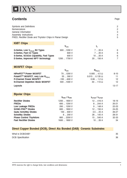
1IXYS reserves the right to change limits, test conditions and dimensions ContentsPage Symbols and Definitions 2Nomenclature2General Information 3A ssembly Instructions4FRED, Rectifier Diode and Thyristor Chips in Planar Design5IGBT ChipsV CESI CG-Series, Low V CE(sat) B2 Types 600 ...1200 V7 ... 20 A 6G-Series, Fast C2 Types600 V 7 ... 20 A 6S-Series, SCSOA Capability, Fast Types 600 V10 ... 20 A 6E-Series, Improved NPT³ technology1200 ... 1700 V20 ... 150 A7MOSFET ChipsV DSSR DS(on)HiPerFET TM Power MOSFET70 ...1200 V 0.005 ... 4.5 Ω8-10PolarHT TM MOSFET, very Low R DS(on)55 ... 300 V 0.015 ... 0.135 Ω11P-Channel Power MOSFET-100 ...-600 V 0.06 ... 1.2 Ω12N-Channel Depletion Mode MOSFET 500 ...1000 V30 ... 110 Ω12Layouts13-17Bipolar ChipsV RRM / V DRMI F(AV)M / I T(AV)M Rectifier Diodes 1200 ... 1800 V 12 ... 416 A 18-19FREDs600 ... 1200 V 8 ... 244 A 20-21Low Leakage FREDs 200 ... 1200 V 9 ... 148 A 22-23SONIC-FRD TM Diodes 600 ... 1800 V 12 ... 150 A 24-25GaAs Schottky Diodes 100 ... 600 V 3.5 ... 25 A 26-27Schottky Diodes8 ... 200 V 28 ... 145 A 28-31Phase Control Thyristors 800 ... 2200 V 15 ... 540 A 32-33Fast Rectifier Diodes1600 ... 1800 V10 ... 26 A34Direct Copper Bonded (DCB), Direct Alu Bonded (DAB) Ceramic SubstratesWhat is DCB/DAB?35DCB Specification362© 2004 IXYS All rights reservedSymbols and DefinitionsC ies Input capacitance of IGBT C iss Input capacitance of MOSFET-di/dt Rate of decrease of forward current I C DC collector current I D Drain currentI FForward current of diodeI F(AV)M Maximum average forward current at specified T h I FSM Peak one cycle surge forward current I GT Gate trigger current I R Reverse currentI RM Maximum peak recovery current I TForward current of thyristorI T(AV)M Maximum average on-state current of a thyristor at specified T hI TSM Maximum surge current of a thyristor R DS(on)Static drain-source on-state resistance R thjc Thermal resistance junction to case r TSlope resistance of a thyristor or diode (for power loss calculations) T case Case temperature T h Heatsink temperaturet fiCurrent fall time with inductive load T j , T (vj)Junction temperatureT jm , T (vj)m Maximum junction temperature t rrReverse recovery time of a diode V CE(sat)Collector-emitter saturation voltage V CES Maximum collector-emitter voltage V DRM Maximum repetitive forward blocking voltage of thyristorV DSS Drain-source break-down voltage V F Forward voltage of diode V R Reverse voltageV RRM Maximum peak reverse voltage of thyristor or diodeV T On-state voltage of thyristorV T0Threshold voltage of thyristors or diodes (for power loss calculation only)Chip and DCB Ceramic Substrates Data book Edition 2004Published by IXYS Semiconductor GmbH Marketing CommunicationsEdisonstraße 15, D-68623 Lampertheim© IXYS Semiconductor GmbH All Rights reserved As far as patents or other rights of third parties are concerned, liability is only assumed for chips and DCB parts per se, not for applications, processes and circuits implemented with components or assemblies. Terms of delivery and the right to change design or specifications are reserved.NomenclatureIGBT and MOSFET DiscreteIXSD 40N60A (Example)IX IXYSDie technology E NPT 3 IGBTF HiPerFETTM Power MOSFETG Fast IGBTS IGBT with SCSOA capability T Standard Power MOSFET D Unassembled chip (die)40Current rating, 40 = 40 A N N-channel type PP-channel type60Voltage class, 60 = 600 Vxx MOSFETA Prime RDS(on) for standard MOSFET Q Low gate charge dieQ2Low gate charge die, 2nd generation P PolarHTTM Power MOSFET L Linear Mode MOSFET IGBT--No letter, low VCE(sat)A Or A2, std speed type B Or B2, high speed typeCOr C2, very high speed type W-CWP 55-12/18(Thyristor Example)WPackage typeC Chip functionC = Silicon phase control thyristor W Unassembled chip PProcess designatorP = Planar passivated chip cathode on top55Current rating value of one chip in A 12/18Voltage class, 12/18 = 1200 up to 1800 VDiode and Thyristor ChipsC-DWEP 69-12(Diode Example)C Package typeD Chip functionD = Silicon rectifier diode W Unassembled chipEPProcess designatorEP = Epitaxial rectifier diodeN = Rectifier diode, cathode on top P = Rectifier diode, anode on topFN = Fast Rectifier diode, cathode on top FP = Fast Rectifier diode, anode on top69Current rating value of one chip in A -12Voltage class, 12 = 1200 V 001947 TS2/765/17557Registration No.:0019473IXYS reserves the right to change limits, test conditions and dimensions General Informations for ChipsWhen mounting Power Semiconductor chips to a header, ceramic substrate or hybrid thick film circuit, the solder system and the chip attach process are very important to the reliability and performance of the final product. This brochure provides several guidelines that describe recommended chip attachment pro-cedures. These methods have been used successfully for many years at IXYS.Available forms of chip packingsIXYS offers various options.Please order from one of the following possibilities:Packaging Options Delivery formC-...*Chips in tray (Waffle Pack);Electrically testedT-...*Chips in wafer, unsawed;Bipolar = 5" (125 mm ∅) wafer;Electrically tested, rejects are inked W-...*Chips in wafer on foil, sawed;Bipolar = 5" (125 mm ∅) wafer;Electrically tested, rejects are inked...* must be amended by the exact chip type designation.Packing, Storage and HandlingChips should be transported in their original containers. All chip transfer to other containers or for assembly should be done only with rubber-tipped vacuum pencils. Contact with human skin (or with a tool that has been touched by hand) leaves an oily residue that may adversely impact subsequent chip attach or reliability.At temperatures below 104°F (40°C), there is no limitation on storage time for chips in sealed original packages. Chips removed from original packages should be assembled immediately. The wetting ability of the contact metallization with solder can be preserved by storage in a clean and dry nitrogen atmosphere.The IGBT and MOSFET Chips are electrostatic discharge (ESD) sensitive. Normal ESD precautions for handling must be observed.Prior to chip attach, all testing and handling of the chips must be done at ESD safe work stations according to DIN IEC 47(CO) 701.Ionized air blowers are recommended for added ESD protection.Contamination of the chips degrades the assembly results.Finger prints, dust or oily deposits on the surface of the chips have to be absolutely avoided.Rough mechanical treatment can cause damage to the chip.Electrical TestsThe electrical properties listed in the data sheet presume correctly assembled chips. Testing ofnon-assembled chips requires the following precautions:-High currents have to be supplied homogeneously to the whole metallized contact area.-Kelvin probes must be used to test voltages at high currents-Applying the full specified blocking or reverse voltage may cause arcing across the glass passivated junction termination, because the electrical field on top of the passivation glass causes ionization of the surrounding air. This phenomenon can be avoided by usinginert fluids or by increasing the pressure of the gas surrounding the chip to values above 30 psig (2 bars).General Rules for AssemblyThe linear thermal expansion coefficient of silicon is very small compared to usual contact metals. If a large area metallized silicon chip is directly soldered to a metal like copper, enormous shear stress is caused by temperature changes (e.g. when cooling down from the solder temperature or by heating during working conditions) which can disrupt the solder mountdown.If it is found that larger chips are cracking during mountdown or in the application, then the use of a low thermal expansion coefficient buffer layer, e.g. tungsten, molybdenum or Trimetal ®, for strain relief should be considered. An alternative solution is to soft-solder these larger chips to DCB ceramic substrates because of their matching thermal expansion coefficients.4© 2004 IXYS All rights reservedMOS/IGBT ChipsRecommended Solder SystemIXYS recommends a soft solder chip attach using a solder composition of 92.5 % Pb, 5 % Sn and 2.5 % Ag. The maximum chip attach temperature is 460°C for MOSFET and 360°C for HiPerFET TM and IGBT.Wire BondingIt is recommended to use wire of diameter not greater than 0.38 mm (0.015") for bonding to the source emitter and gate pads. Multiple wires should be used in place of thicker wire to handle high drain or emitter currents. See tables for number of recommended wire bonds. At smaller gate pads 0.15 mm is recommended.Thermal Response TestingTo assure good chip attach processing, thermal response testing per MIL STD 750, Method 3161 or equivalent should be performed.Bipolar ChipsAssemblingIXYS bipolar semiconductor chips have a soft-solderable, multi-layer metallization (Ti/Ni/Ag) on the bottom side and, on top, either the same metallization scheme or an alumunium layer sufficiently thick for ultrasonic bonding. Note that the last layer of metal for soldering is pure silver.Regardless of their type all chips possess the same glass passivated junction termination system on top of the chip. For that reason they can be easily chip bonded or they can all be simply soldered to a flat contacting electrode in accordance to the General Rules on Page 3. All kinds of the usual soft solders with melting points below 660°F (350°C) can be used thanks to their pure silver top metal.Solders with high melting points are preferable due to their better power cycling capability, i.e. they are more resistant to thermal fatigue.Soldering temperature should not exceed 750°F (400°C). The maximum temperature should not be applied for more than five minutes.As already mentioned above the electrical properties quoted in the data sheets can only be obtained with properly assembled chips.This is only possible when all contact materials to be soldered together are well wetted and the solder is practically free of voids.A simple means to achieve good solder connections is to use a belt furnace running with a process gas containing at least 10 %Hydrogen in Nitrogen.Other approved methods are also allowed, provided that the above mentioned temperature-time-limits are not exceeded and temperature shocks above 930°F/min (500 K/min) are avoided.We do not recommend the use of fluxes for soldering!Ultrasonic Wire BondingChips provided with a thick aluminium layer are designed for ultrasonic wire bonding. Wire diameters up to 500 µm can be used dependent on chip types. Setting wires in parallel and application of stitch bonding lead to surge current ratings comparable to soldered chips.CoatingAlthough the chips are glass passivated, they must be protected against arcing and environmental influences. The coating material that is in contact with the chip surface must have the following properties:- elasticity (to prevent mechanical stress)- high purity, no contamination with alkali metals - good adhesion to metals and glass passivation.Assembly Instructions5IXYS reserves the right to change limits, test conditions and dimensionsFRED, Rectifier Diode and Thyristor Chips in Planar DesignFast Recovery Epitaxial Diodes (FRED)Power switches (IGBT, MOSFET, BJT, GTO) for applications in electronics are only as good as their associated free-wheeling diodes. At increasing switching frequencies, the proper functioning and efficiency of the power switch, aside from conduction losses,is determined by the turn-off behavior of the diode (characterized by Q rr , I RM and t rr - Fig. 1.Rectifier Diode and Thyristor ChipsThe figures 3 a-c show cross sectional views of the diode and thyristor chips in the passivation area. All thyristor and diode chips (DWN, DWFN,CWP) are fabricated using separation diffusion processes so that all junctions terminate on the topside of the chip. Now the entire bottom surfaces of all chips are available for soldering onto a DCB or other ceramic substrate without a molybdenum strain buffer. The elimination of the strain buffer and its solder joint reduces thermal resistance and increases blocking voltage stability. The junction termination areas are passivated with glass, whose thermal expansion coefficient matches that of silicon. All silicon chips increasingly use planar technology with guard rings and channel stoppers to reduce electric fields on the chip surface.The contact areas of the chips have vapor deposited metal layers which contribute substantially to their high power cycle capability. All chips are processed on silicon wafers of 5" diameter and diced after a wafer sample test which auto-matically marks chips not meeting the electrical specification.The chip geometry is square or rectangular.Fig. 3a-cCross sections of Chips in the passivation area a) Diode chip, type DWN, DWFN b) Diode chip, type DWP, DWFP c) Thyristor chip, type CWPThe reverse current character-istic following the peak reverse current I RM is another very im-portant property. The slope of the decaying reverse current di rr /dt results from design para- meters (technology and dif-fusion of the FRED chip Fig. 2. In a circuit this current slope, in conjunction with parasitic induc-tances (e.g. connecting leads, causes over-voltage spikes and high frequency interference vol-tages.The higher the di rr /dt ("hard recovery" or "snap-off" behavior) the higher is the resulting additional stress for both the diode and the paralleled switch. A slow decay of the reverse current ("soft recovery" behavior), is the most desirable characteristic, and this is designed into all FRED. The wide range of available blocking voltages makes it possible to apply these FRED as output rectifiers in switch-mode power supplies (SMPS) as well as protective and free-wheeling diodes for power switches in inverters and welding power supplies.MetalizationFig. 1:Current and voltage during turn-on andturn-offswitching of fast diodesFig. 2:Cross section of glassivated planar epitaxial diode chip with seperation diffusion (type DWEP)Epitaxie Sch ich t n -Sub stra t n+KathodeAnodeGuard ringSubstrate n+Epitaxy layer n-CathodeAnode Glasspassivation p n n +GlasspassivationGuard ring Metalization Fig. 3b)MetalizationChannel-stopperGlasspassivationGuard ring EmitterFig. 3c)Fig. 3a)18© 2004 IXYS All rights reservedRectifier DiodesTypeV RRMVDWN 5800 -DWP 51200DWN 21200 -DWN 91800DWN 17 DWP 17DWN 21DWP 21DWN 35DWP 35DWN 50DWP 50DWN 75DWP 75DWN 110DWP 110DWN 340DWN 1081600 -1Mounted on DCB19© 2004 IXYS All rights reservedDWNDWPRectifier DiodesTypeDWN 5DWP 5DWN 2•DWN 9•DWN 17 •DWP 17•DWN 21•DWP 21•DWN 35•DWP 35•DWN 50•DWP 50DWN 75•DWP 75•DWN 110•DWP 110•DWN 340•DWN 108•s o l d e r a b l e20© 2004 IXYS All rights reserved FRED - F ast R ecovery E pitaxial DiodesTypeV RRMVDWEP 27-02200DWEP 37-02DWEP 77-02DWEP 8-06600DWEP 12-06DWEP 15-06DWEP 23-06DWEP 25-06DWEP 35-06DWEP 55-06DWEP 75-06DWEP 3-101000DWEP 10-10DWEP 18-10DWEP 20-10DWEP 30-10DWEP 50-101 Mounted on DCB21© 2004 IXYS All rights reserved FRED - F ast R ecovery E pitaxial DiodesTypeDWEP 27-02•DWEP 37-02•DWEP 77-02••DWEP 8-06•DWEP 12-06••DWEP 15-06••DWEP 23-06••DWEP 25-06••DWEP 35-06••DWEP 55-06•DWEP 75-06••DWEP 3-10•DWEP 10-10•DWEP 18-10•DWEP 20-10•DWEP 30-10••DWEP 50-10•s o l d e r a b l eb o n d a b l e22© 2004 IXYS All rights reservedLow Leakage Fast Recovery Epitaxial DiodesTypeV RRM VDWLP 4-02200DWLP 15-02DWLP 15-02B DWLP 25-02DWLP 4-03300DWLP 8-03DWLP 15-03DWLP 15-03A DWLP 23-03DWLP 23-03A DWLP 55-03DWLP 75-03DWLP 8-04400DWLP 15-04DWLP 23-04DWLP 55-04DWLP 75-04DWLP 150-04DWLP 4-066001Mounted on DCB23© 2004 IXYS All rights reservedLow Leakage Fast Recovery Epitaxial DiodesTypeDWLP 4-02•DWLP 15-02•DWLP 15-02B •DWLP 25-02•DWLP 4-03•DWLP 8-03•DWLP 15-03•DWLP 15-03A •DWLP 23-03•DWLP 23-03A •DWLP 55-03••DWLP 75-03•DWLP 8-04•DWLP 15-04•DWLP 23-04•DWLP 55-04••DWLP 75-04••DWLP 150-04••DWLP 4-06•s o l d e r a b l eb o n d a b l e24© 2004 IXYS All rights reserved SONIC-FRD TMDiodesTypeV DWHP 8-06 F in design DWHP 15-06 F 600DWHP 23-06 FDWHP 56-06 F DWHP 69-06 F DWHP 150-06 F in design DWHFP 15-12 F 1200DWHFP 23-12 F DWHFP 56-12 F DWHFP 56-12 S DWHFP 69-12 F DWHFP 69-12 S DWHFP 150-12 S DLFP 55-17 S 1700DLFP 68-17 S DLFP 150-17 S DLFP 200-17 S 1Mounted on DCB25© 2004 IXYS All rights reserved SONIC-FRD TMDiodesTypeDWHP 8-06 F DWHP 15-06 F DWHP 23-06 F DWHP 56-06 F DWHP 69-06 F DWHP 150-06 F DWHFP 15-12 F DWHFP 23-12 FDWHFP 56-12 F DWHFP 56-12 SDWHFP 69-12 F DWHFP 69-12 S DWHFP 150-12 S DLFP 55-17 S DLFP 68-17 S DLFP 150-17 S DLFP 200-17 S s o l d e r a b l e26© 2004 IXYS All rights reservedGaAs Schottky DiodesTypeV RRMVDWGS04-01A 100DWGS10-01C DWGS04-018A 180DWGS04-018CDWGS10-018ADWGS10-018C DWGS20-018A DWGS20-018C DWGS04-025A 250DWGS04-025C DWGS10-025A DWGS10-025C DWGS20-025A DWGS20-025C DWGS04-03A 300DWGS04-03C DWGS10-03A27© 2004 IXYS All rights reservedGaAs Schottky DiodesD W GS04-01A D W GS10-01CD W GS04-018A D W GS04-018C D W GS10-018A D W GS10-018C D W GS20-018A D W GS20-018C D W GS04-025A D W GS04-025C D W GS10-025A D W GS10-025C D W GS20-025A D W GS20-025C D W GS04-03A D W GS04-03C D W GS10-03A s o l d e r a b l e28© 2004 IXYS All rights reservedSchottky DiodesTypeV RRMVDWS 39-08D DWS 9-15B 15DWS 19-15B DWS 29-15B DWS 7-30B 30DWS 17-30B DWS 27-30B DWS 37-30B DWS 217-30B DWS 3-45B 45DWS 4-45A DWS 13-45B DWS 14-45A DWS 23-45B DWS 24-45A DWS 33-45B 1Mounted on DCB29© 2004 IXYS All rights reservedSchottky DiodesTypeDWS 39-08D •DWS 9-15B •DWS 19-15B •DWS 29-15B •DWS 7-30B •DWS 17-30B •DWS 27-30B•DWS 37-30B •DWS 217-30B •DWS 3-45B •DWS 4-45A •DWS 13-45B •DWS 14-45A •DWS 23-45B ••DWS 24-45A •DWS 33-45B ••s o l d e r a b l eb o n d a b l e30© 2004 IXYS All rights reservedSchottky DiodesTypeV RRMVDWS 5-60A 60DWS 15-60BDWS 25-60BDWS 35-60B DWS 25-80B 80DWS 36-80A DWS 2-100A 100DWS 12-100A DWS 22-100A DWS 32-100A DWS 1-150A 150DWS 11-150A DWS 21-150A DWS 31-150A DWS 1-180A 1801 Mounted on DCB31© 2004 IXYS All rights reservedSchottky DiodesTypeDWS 5-60A •DWS 15-60B •DWS 25-60B •DWS 35-60B •DWS 25-80B •DWS 36-80A •DWS 2-100A •DWS 12-100A •DWS 22-100A •DWS 32-100A ••DWS 1-150A •DWS 11-150A •DWS 21-150A •DWS 31-150A •DWS 1-180A •s o l d e r a b l eb o n d a b l e32© 2004 IXYS All rights reservedPhase Control ThyristorsTypeV DRM V RRMVCWP 7-CG 800 -CWP 81200CWP 8-CG CWP 35CWP 16-CG 1200 -CWP 21-CG 1600 -CWP 22-CG CWP 24CWP 25-CG CWP 411200 -CWP 501800CWP 55CWP 71CWP 130CWP 180CWP 341CWP 3471Mounted on DCB33© 2004 IXYS All rights reservedPhase Control Thyristors...-CG typesTypeCWP 7-CG ••CWP 8••CWP 8-CG•CWP 35••CWP 16-CG ••CWP 21-CG ••CWP 22-CG ••CWP 24••CWP 25-CG ••CWP 41••CWP 50••CWP 55••CWP 71••CWP 130••CWP 180••CWP 341•CWP 347•s o l d e r a b l eb o n d a b l e34© 2004 IXYS All rights reservedDWFN DWFPFast Rectifier DiodesTypeV RRMVDWFN 2-16/181600 -DWFN 9-16/181800DWFN 17-16/18DWFP 17-16/18DWFN 21-16/18DWFN 35-16/181 Mounted on DCBTypeo l d e r a b l e。
- 1、下载文档前请自行甄别文档内容的完整性,平台不提供额外的编辑、内容补充、找答案等附加服务。
- 2、"仅部分预览"的文档,不可在线预览部分如存在完整性等问题,可反馈申请退款(可完整预览的文档不适用该条件!)。
- 3、如文档侵犯您的权益,请联系客服反馈,我们会尽快为您处理(人工客服工作时间:9:00-18:30)。
General DescriptionThe DS32x35 accurate real-time clock (RTC) is a tem-perature-compensated clock/calendar that includes an integrated 32.768kHz crystal and a bank of nonvolatile memory in a single package. The nonvolatile memory is available in two densities: 2048 x 8 and 8192 x 8 bits.The integration of the crystal resonator enhances the long-term accuracy of the device as well as reduces the piece part count in a manufacturing line. The device operates as a slave device on an I 2C serial interface,and is available in both commercial and industrial tem-perature ranges in a 300-mil, 20-pin SO package.The DS32x35 includes a bank of nonvolatile memory that does not require a backup energy source to main-tain memory contents. In addition, there are no read or write cycle limitations. The memory array can be accessed at maximum cycle rates for the life of the product with no wear-out mechanisms.Other device features include two time-of-day alarms, a selectable output that provides either an interrupt or pro-grammable square wave, and a calibrated 32.768kHz square-wave output. A reset input/output pin provides a power-on reset. Additionally, the reset pin is monitored as a pushbutton input for generating a reset externally.A precision temperature-compensated reference and comparator circuit monitors the status of V CC and auto-matically switches to the backup supply when neces-sary. The backup supply maintains operation of the TCXO, clock, alarms, and RTC I 2C operation.ApplicationsServers Utility Power Meters TelematicsGPSFeatureso Integrated 32.768kHz Crystal o Fast (400kHz) I 2C Interfaceo RTC Counts Seconds, Minutes, Hours, Day, Date,Month, and Year with Leap Year Compensation Valid Up to 2100o RTC Accuracy ±2ppm from 0°C to +40°Co RTC Accuracy ±3.5ppm from -40°C to 0°C and +40°C to +85°Co Nonvolatile Memory with 10 Years of Guaranteed Backup Time and Write Protectiono Two Available Densities of Nonvolatile Memory2048 Bytes (DS32B35)8192 Bytes (DS32C35)o No Cycle Limitations on Memoryo Power-Switching Circuit Selects Between Main Power and Battery Backup for the RTCo Programmable Square Wave with Frequency of 32.768kHz, 8.192kHz, 4.096kHz, or 1Hz o Two Time-of-Day Alarmso Reset Output/Pushbutton Reset (Debounced)Inputo Programmable Output Provides Interrupt or Square Waveo Calibrated 32.768kHz Open-Drain Output o Temp Sensor with ±3°C Accuracy o 3.3V Operating Voltageo Commercial and Industrial Temperature Ranges o 300-mil, 20-Pin SO Packageo Underwriters Laboratories (UL) RecognizedDS32x35Accurate I 2C RTC with IntegratedTCXO/Crystal/FRAM______________________________________________Maxim Integrated Products 1Rev 0; 12/06For pricing, delivery, and ordering information,please contact Maxim Direct at 1-888-629-4642,or visit Maxim’s website at .Pin Configuration and Ordering Information appear at end of data sheet.D S 32x 35Accurate I 2C RTC with Integrated TCXO/Crystal/FRAM 2_____________________________________________________________________ABSOLUTE MAXIMUM RATINGSRECOMMENDED DC OPERATING CONDITIONSStresses beyond those listed under “Absolute Maximum Ratings” may cause permanent damage to the device. These are stress ratings only, and functional operation of the device at these or any other conditions beyond those indicated in the operational sections of the specifications is not implied. Exposure to absolute maximum rating conditions for extended periods may affect device reliability.Voltage Range on Any Pin Relative to Ground......-0.3V to +5.0V Operating Temperature Range ..........................-40°C to +85°C Junction Temperature......................................................+125°C Storage Temperature Range...............................-40°C to +85°CLead Temperature (soldering, 10s).................................+260°C Soldering Temperature....................................................See theIPC/JEDEC J-STD-020 SpecificationELECTRICAL CHARACTERISTICSDS32x35Accurate I 2C RTC with IntegratedTCXO/Crystal/FRAM_____________________________________________________________________3ELECTRICAL CHARACTERISTICS (continued)ELECTRICAL CHARACTERISTICSD S 32x 35Accurate I 2C RTC with Integrated TCXO/Crystal/FRAM 4_____________________________________________________________________AC ELECTRICAL CHARACTERISTICSDS32x35Accurate I 2C RTC with IntegratedTCXO/Crystal/FRAM_____________________________________________________________________5POWER-SWITCH CHARACTERISTICSNote 1:Limits at -40°C are guaranteed by design and not production tested.Note 2:All voltages are referenced to ground.Note 3:To minimize current drain on V BAT when the internal supply is switched to V BAT , the V IH minimum must be higher thanV BAT - 0.6V. Otherwise, there is significant current drain due to the input stage at the SCL and SDA pins.Note 4:The pullup resistor voltage on the 32kHz and INT /SQW pins can be up to 5.5V maximum regardless of the voltage on V CC .Note 5:Current is the averaged input current, which includes the temperature conversion current.Note 6:The RST pin has an internal 50k Ω(nominal) pullup resistor to V CC .Note 7:After this period, the first clock pulse is generated.Note 8: A device must internally provide a hold time of at least 300ns for the SDA signal (referred to as the V IH(MIN)of the SCL sig-nal) to bridge the undefined region of the falling edge of SCL.Note 9:The maximum t HD:DAT needs only to be met if the device does not stretch the low period (t LOW ) of the SCL signal.Note 10:A fast-mode device can be used in a standard-mode system, but the requirement t SU:DAT ≥250ns must then be met. Thisis automatically the case if the device does not stretch the low period of the SCL signal. If such a device does stretch the low period of the SCL signal, it must output the next data bit to the SDA line t R(MAX)+ t SU:DAT = 1000 + 250 = 1250ns before the SCL line is released.Note 11:C B —total capacitance of one bus line in pF.Note 12:The parameter t OSF is the period of time the oscillator must be stopped for the OSF flag to be set over the voltage range of0.0V ≤V CC ≤V CC(MAX) and 2.0V ≤V BAT ≤3.6V.Note 13:This delay applies only if the oscillator is enabled and running. If the EOSC bit is a 1, t REC is bypassed and RST immediate-ly goes high.D S 32x 35Accurate I 2C RTC with Integrated TCXO/Crystal/FRAM 6_____________________________________________________________________Pushbutton Reset TimingPower-Switch TimingDS32x35Accurate I 2C RTC with IntegratedTCXO/Crystal/FRAM_____________________________________________________________________7SUPPLY CURRENT vs. TEMPERATURETEMPERATURE (°C)I B A T (μA )80.060.040.020.00.0-20.00.7000.8000.9001.0000.600-40.0FREQUENCY DEVIATION vs.TEMPERATURE vs. AGING VALUECRYSTAL AGING REGISTER VALUEF R E Q U E N C Y D E V I A T I O N (p p m )966432-64-32-96-40-30-20-100102030405060-128128STANDBY SUPPLY CURRENT vs. SUPPLY VOLTAGEV CC (V)I C C S (μA )5.04.03.05010015002.0SUPPLY CURRENT vs. SUPPLY VOLTAGEV BAT (V)I B A T (μA )5.04.03.00.8000.9001.0001.1001.2000.7002.0Typical Operating Characteristics(V CC = +3.3V, T A = +25°C, unless otherwise noted.)D S 32x 35Accurate I 2C RTC with Integrated TCXO/Crystal/FRAM 8_____________________________________________________________________Block DiagramDS32x35Accurate I 2C RTC with IntegratedTCXO/Crystal/FRAM_____________________________________________________________________9Detailed DescriptionThe DS32x35 accurate RTC is a temperature-compen-sated clock/calendar that includes an integrated 32.768kHz crystal and a bank of nonvolatile memory in a single package. The nonvolatile memory is available in two sizes: 2048 x 8 or 8192 x 8 bits. The integration of the crystal resonator enhances the long-term accura-cy of the device as well as reduces the piece part count in a manufacturing line. The device is available in both commercial and industrial temperature ranges and is offered in a 300-mil, 20-pin SO package.The DS32x35 includes a bank of nonvolatile memory that does not require a backup energy source to main-tain the memory contents. In addition, there are no readaccessed at maximum cycle rates for the life of the product with no wear-out mechanisms.A precision temperature-compensated reference and comparator circuit monitors the status of V CC and auto-matically switches to the backup supply when neces-sary. Other device features include two time-of-day alarms, a selectable output that provides either an interrupt or programmable square wave, and a calibrat-ed 32.768kHz square-wave output. A reset input/output pin provides a power-on reset. Additionally, the reset pin is monitored as a pushbutton input for generating a reset externally. The device is accessed through an I 2C serial interface.D S 32x 35Accurate I 2C RTC with Integrated TCXO/Crystal/FRAM 10____________________________________________________________________OperationThe Block Diagram shows the main elements of the DS32x35. The nine blocks can be grouped into six functional groups: TCXO, power control, pushbutton function, RTC, I 2C interface, and F RAM. Their opera-tions are described separately in the following sections.32kHz TCXOThe temperature sensor, oscillator, and control logic form the TCXO. The controller reads the output of the on-chip temperature sensor and uses a lookup table to determine the capacitance required, adds the aging correction in the AGE register, and then sets the capacitance selection registers. New values, including changes to the AGE register, are loaded only when a change in the temperature value occurs, or when a user-initiated temperature conversion is completed.The temperature is read on initial application of V CC and once every 64 seconds afterwards while the device is powered by either V CC or V BAT .Power ControlThis function is provided by a temperature-compensat-ed voltage reference and a comparator circuit that monitors the V CC level. When V CC is greater than V PF ,the part is powered by V CC . When V CC is less than V PF but greater than V BAT , the RTC is powered by V CC . If V CC is less than V PF and is less than V BAT , the device is powered by V BAT . See Table 1.The RTC can be accessed when the device is powered by either V CC or V BAT . The F RAM is only accessible when the device is powered by V CC . The F RAM must not be accessed when V CC < V CC(MIN).To preserve the battery, the first time V BAT is applied to the device, the oscillator will not start up until V CC exceeds V PF , or until a valid I 2C address is written to the part. Typical oscillator startup time is less than one sec-ond. Approximately 2 seconds after V CC is applied, or a valid I 2C address is written, the device makes a temper-ature measurement and applies the calculated correc-tion to the oscillator. Once the oscillator is running, itcontinues to run as long as a valid power source is avail-able (V CC or V BAT ), and the device continues to mea-sure the temperature and correct the oscillator frequency every 64 seconds.Pushbutton Reset FunctionThe DS32x35 provides for a pushbutton switch to be con-nected to the RST output pin. When the device is not in a reset cycle, it continuously monitors the RST signal for a low going edge. If an edge transition is detected, the device debounces the switch by pulling RST low. After the internal timer has expired (PB DB ), the device contin-ues to monitor the RST line. If the line is still low, the device continuously monitors the line looking for a rising edge. Upon detecting release, the device forces the RST pin low and holds it low for t RST .RST is also used to indicate a power-fail condition.When V CC is lower than V PF , an internal power-fail sig-nal is generated, which forces the RST pin low. When V CC returns to a level above V PF , the RST pin is held low for t REC to allow the power supply to stabilize. If the oscillator is not running (see the Power Control section)when V CC is applied, t REC is bypassed and RST imme-diately goes high. The state of RST does not affect the operation of the TCXO, I 2C interface, F RAM, or RTC functions.Real-Time ClockWith the clock source from the TCXO, the RTC provides seconds, minutes, hours, day, date, month, and year information. The date at the end of the month is automati-cally adjusted for months with fewer than 31 days, includ-ing corrections for leap year. The clock operates in either the 24-hour or 12-hour format with an AM /PM indicator.The clock provides two programmable time-of-dayalarms and a programmable square-wave output. TheINT /SQW pin either generates an interrupt due to alarmcondition or outputs a square-wave signal and theselection is controlled by the bit INTCN.I 2C InterfaceThe FRAM I 2C interface is accessible whenever VCC isat a valid level. The RTC I 2C interface is accessiblewhenever either V CC or V BAT is at a valid level. If a microcontroller connected to the device resets becauseof a loss of V CC or other event, it is possible that the microcontroller and the RTC I 2C communications could become unsynchronized, e.g., the microcontroller resets while reading data from the RTC. When the microcon-troller resets, the RTC I 2C interface may be placed into a known state by toggling SCL until SDA is observed to be at a high level. At that point the microcontroller should pull SDA low while SCL is high, generating a START condition.DS32x35Accurate I 2C RTC with IntegratedTCXO/Crystal/FRAMFRAMThe serial F RAM memory is logically organized as a 2048 x 8 or 8192 x 8 memory array and is accessed using the I 2C interface. F unctional operation of the F RAM is similar to serial EEPROMs with the major dif-ference being its superior performance on writes. The memory is read or written at the speed of the I 2C inter-face. It is not necessary to poll the device for a ready condition during writes.Due to the different memory densities, the I 2C address-ing technique is different for each version of the DS32x35. See the I 2C Serial Data Bus section for details.Warning:The F RAM does not inhibit reads or writeswhen V CC is below the minimum operating voltage.F RAM reads are destructive, that is, when a read is performed, the device internally writes the memory back to the original value. The FRAM must not be read or written when V CC is below the minimum operating voltage; otherwise, the memory cells may not be fully programmed, and the data may not be retained.RTC Address MapTable 3 shows the RTC address map for the DS32x35timekeeping registers. During a multibyte access, when the address pointer reaches the end of the register space, it wraps around to location 00h. On an I 2C START or address pointer incrementing to location 00h,the current time is transferred to a second set of regis-ters. The time information is read from these secondary registers, while the clock continues to run. This elimi-nates the need to reread the registers in case the main registers update during a read.Clock and CalendarThe time and calendar information is obtained by read-ing the appropriate register bytes. Table 3 illustrates the RTC registers. The time and calendar data are set or ini-tialized by writing the appropriate register bytes. The con-tents of the time and calendar registers are in the binary-coded decimal (BCD) format. The DS32x35 can be run in either 12-hour or 24-hour mode. Bit 6 of the hours register is defined as the 12- or 24-hour mode select bit. When high, the 12-hour mode is selected. In the 12-hour mode, bit 5 is the AM /PM bit with logic-high being PM. In the 24-hour mode, bit 5 is the second 10-hour bit (20 to 23 hours). The century bit (bit 7 of the month register) is toggled when the years register over-flows from 99 to 00.The day-of-week register increments at midnight.Values that correspond to the day of week are user-defined but must be sequential (i.e., if 1 equals Sunday, then 2 equals Monday, and so on). Illogical time and date entries result in undefined operation.When reading or writing the time and date registers, sec-ondary (user) buffers are used to prevent errors when the internal registers update. When reading the time and date registers, the user buffers are synchronized to the internal registers on any START and when the register pointer rolls over to zero. The time information is read from these secondary registers while the clock continues to run. This eliminates the need to reread the registers in case the main registers update during a read.The countdown chain is reset whenever the seconds register is written. Write transfers occur on the acknowl-edge from the DS32x35. Once the countdown chain is reset, to avoid rollover issues the remaining time and date registers must be written within 1 second. The 1Hz square-wave output, if enabled, transitions high 500ms after the seconds data transfer, provided that the oscil-lator is already running.D S 32x 35Accurate I 2C RTC with Integrated TCXO/Crystal/FRAM Table 3. RTC Register MapDS32x35AlarmsThe DS32x35 contains two time-of-day/date alarms.Alarm 1 can be set by writing to registers 07h to 0Ah.Alarm 2 can be set by writing to registers 0Bh to 0Dh.The alarms can be programmed (by the alarm enable and INTCN bits of the Control register) to activate the INT /SQW output on an alarm match condition. Bit 7 of each of the time-of-day/date alarm registers are mask bits (Table 4). When all the mask bits for each alarm are logic 0, an alarm only occurs when the values in the timekeeping registers match the corresponding values stored in the time-of-day/date alarm registers. The alarms can also be programmed to repeat every sec-ond, minute, hour, day, or date. Table 4 shows thepossible settings. Configurations not listed in the table will result in illogical operation.The DY/DT bits (bit 6 of the alarm day/date registers)control whether the alarm value stored in bits 0 to 5 of that register reflects the day of the week or the date of the month. If DY/DT is written to logic 0, the alarm is the result of a match with date of the month. If DY/DT is written to logic 1, the alarm is the result of a match with day of the week.When the RTC register values match alarm register set-tings, the corresponding Alarm Flag (“A1F”) or (“A2F”)bit is set to logic 1. If the corresponding alarm interrupt enable (“A1IE”) or (“A2IE”) is also set to logic 1 and the INTCN bit is set to logic 1, the alarm condition will acti-vate the INT /SQW signal.Accurate I 2C RTC with IntegratedTCXO/Crystal/FRAMD S 32x 35Accurate I 2C RTC with Integrated TCXO/Crystal/FRAM Special-Purpose RegistersControl Register (0Eh)Bit 7: Enable Oscillator (EOSC ). When set to logic 0,the oscillator is started. When set to logic 1, the oscilla-tor is stopped when the DS32x35 switches to V BAT .This bit is clear (logic 0) when power is first applied.When the DS32x35 is powered by V CC , the oscillator is always on regardless of the status of the EOSC bit.Bit 6: Battery-Backed Square-Wave Enable (BBSQW). When set to logic 1 and the DS32x35is being powered by the V BAT pin, this bit enables the square-wave or interrupt output when V CC is absent.When BBSQW is logic 0, the INT /SQW pin goes high impedance when V CC falls below the power-fail trip point. This bit is disabled (logic 0) when power is first applied.Bit 5: Convert Temperature (CON V). When the DS32x35 is in idle state, setting this bit to 1 forces the temperature sensor to convert the temperature into dig-ital code and execute the TCXO algorithm to update the capacitance load for the oscillator. This can only happen when a conversion is not already in progress.The user should check the status bit BSY before forcing the controller to start a new TCXO execution. A user-ini-tiated temperature conversion does not affect the inter-nal 64-second update cycle.Bits 4 and 3: Rate Select (RS2 and RS1). These bits control the frequency of the square-wave output when the square wave has been enabled. Table 5 shows the square-wave frequencies that can be selected with the RS bits. These bits are both set to logic 1 (8.192kHz)when power is first applied.Bit 2: Interrupt Control (INTCN). This bit controls the INT /SQW signal. When the INTCN bit is set to logic 0, a square wave is output on the INT /SQW pin. When the INTCN bit is set to logic 1, then a match between the timekeeping registers and either of the alarm registers activates the INT /SQW output (if the alarm is also enabled). The corresponding alarm flag is always set regardless of the state of the INTCN bit. The INTCN bit is set to logic 1 when power is first applied.Bit 1: Alarm 2 Interrupt Enable (A2IE).When set to logic 1, this bit permits the alarm 2 flag (A2F) bit in the status register to assert INT /SQW (when INTCN = 1).When the A2IE bit is set to logic 0 or INTCN is set to logic 0, the A2F bit does not initiate an interrupt signal.The A2IE bit is disabled (logic 0) when power is first applied.Bit 0: Alarm 1 Interrupt Enable (A1IE).When set to logic 1, this bit permits the alarm 1 flag (A1F) bit in the status register to assert INT /SQW (when INTCN = 1).When the A1IE bit is set to logic 0 or INTCN is set to logic 0, the A1F bit does not initiate the INT /SQW sig-nal. The A1IE bit is disabled (logic 0) when power is first applied.DS32x35Accurate I 2C RTC with IntegratedTCXO/Crystal/FRAMBit 7: Oscillator Stop Flag (OSF). A logic 1 in this bit indicates that the oscillator either is stopped or was stopped for some period and may be used to judge the validity of the timekeeping data. This bit is set to logic 1any time that the oscillator stops. The following are examples of conditions that can cause the OSF bit to be set:1)The first time power is applied.2)The voltages present on both V CC and V BAT are insufficient to support oscillation.3)The EOSC bit is turned off in battery-backed mode.4)External influences on the crystal (i.e., noise, leak-age, etc.).This bit remains at logic 1 until written to logic 0.Bit 3: Enable 32kHz Output (EN32kHz).This bit con-trols the status of the 32kHz pin. When set to logic 1,the 32kHz pin is enabled and outputs a 32.768kHz square-wave signal. When set to logic 0, the 32kHz pin goes to a high-impedance state. The initial power-up state of this bit is logic 1, and a 32.768kHz square-wave signal appears at the 32kHz pin after a V CC is applied to the DS32x35.Bit 2: Busy (BSY).This bit indicates the device is busy executing TCXO functions. It goes to logic 1 when the conversion signal to the temperature sensor is asserted and then is cleared when the device is in the 1-minuteCONV signal from aborting the execution of the TCXO algorithm and starting a new execution of TCXO function.Bit 1: Alarm 2 Flag (A2F).A logic 1 in the alarm 2 flag bit indicates that the time matched the alarm 2 regis-ters. If the A2IE bit is logic 1 and the INTCN bit is set to logic 1, the INT /SQW pin is also asserted. A2F is cleared when written to logic 0. This bit can only be written to logic 0. Attempting to write to logic 1 leaves the value unchanged.Bit 0: Alarm 1 Flag (A1F).A logic 1 in the alarm 1 flag bit indicates that the time matched the alarm 1 regis-ters. If the A1IE bit is logic 1 and the INTCN bit is set to logic 1, the INT /SQW pin is also asserted. A1F is cleared when written to logic 0. This bit can only be written to logic 0. Attempting to write to logic 1 leaves the value unchanged.Aging Offset Register (10h)The Aging Offset register provides an 8-bit code to add to the codes in the capacitance array registers. The code is encoded in two’s complement. One LSB repre-sents one small capacitor to be switched in or out of the capacitance array at the crystal pins.The change in ppm per LSB is different at different temper-atures. The frequency vs. temperature curve is distorted by the values used in this register. At +23°C, one LSB typi-cally provides approximately 0.1ppm change in frequency.D S 32x 35Accurate I 2C RTC with Integrated TCXO/Crystal/FRAMTemperature Registers (11h–12h)Temperature is represented as a 10-bit code with a res-olution of +0.25°C and is accessible at location 11h and 12h. The temperature is encoded in two’s comple-ment format. The upper 8 bits are at location 11h, and the lower 2 bits are in the upper nibble at location 12h.Upon power reset, the registers are set to a defaulttemperature of 0°C and the controller starts a tempera-ture conversion. New temperature readings are stored in this register.FRAM Address MapDuring a multibyte access, the address pointer wraps around to location 00h when it reaches the end of the register space.DS32x35Accurate I 2C RTC with IntegratedTCXO/Crystal/FRAMI 2C Serial Data BusThe DS32x35 supports a bidirectional I 2C bus and data transmission protocol (F igure 1). A device that sends data onto the bus is defined as a transmitter, and a device receiving data is defined as a receiver. The device that controls the message is called a master.The devices that are controlled by the master are slaves. The bus must be controlled by a master device that generates the serial clock (SCL), controls the bus access, and generates the START and STOP condi-tions. The DS32x35 operates as a slave on the I 2C bus.Connections to the bus are made through the SCLinput and open-drain SDA I/O lines. Within the bus specifications, a standard mode (100kHz maximum clock rate) and a fast mode (400kHz maximum clock rate) are defined. The DS32x35 works in both modes.The following bus protocol has been defined (Figure 2):•Data transfer can be initiated only when the bus is not busy.•During data transfer, the data line must remain stable whenever the clock line is high. Changes in the data line while the clock line is high are interpreted as control signals.Figure 2. I C Data Transfer OverviewFigure 1. Data Transfer on I C Serial BusD S 32x 35Accurate I 2C RTC with Integrated TCXO/Crystal/FRAM Accordingly, the following bus conditions have been defined:Bus not busy:Both data and clock lines remain high.Start data transfer:A change in the state of the data line from high to low, while the clock line is high,defines a START condition.Stop data transfer:A change in the state of the data line from low to high, while the clock line is high,defines a STOP condition.Data valid:The state of the data line represents valid data when, after a START condition, the data line is stable for the duration of the high period of the clock signal. The data on the line must be changed during the low period of the clock signal. There is one clock pulse per bit of data.Each data transfer is initiated with a START condition and terminated with a STOP condition. The number of data bytes transferred between the START and the STOP conditions is not limited, and is determined by the master device. The information is transferred byte-wise and each receiver acknowledges with a ninth bit.Acknowledge:Each receiving device, when addressed, is obliged to generate an acknowledge after the reception of each byte. The master device must generate an extra clock pulse, which is associ-ated with this acknowledge bit.A device that acknowledges must pull down the SDA line during the acknowledge clock pulse in such a way that the SDA line is stable low during the high period of the acknowledge-related clock pulse. Of course, setup and hold times must be taken into account. A master must signal an end of data to the slave by not generating an acknowledge bit on the last byte that has been clocked out of the slave. In this case, the slave must leave the data line high to enable the master to generate the STOP condition.Depending upon the state of the R/W bit, two types of data transfer are possible:1)Data transfer from a master transmitter to a slave receiver. The first byte transmitted by the master is the slave address. Next follows a num-ber of data bytes. The slave returns an acknowl-edge bit after each received byte. Data is transferred with the most significant bit (MSB) first.2)Data transfer from a slave transmitter to a master receiver. The first byte (the slave address) is transmitted by the master. The slave then returns an acknowledge bit. Next follows a number of data bytes transmitted by the slave to the master. The master returns an acknowledge bit after all received bytes other than the last byte.At the end of the last received byte, a not acknowledge is returned.The master device generates all the serial clock pulses and the START and STOP conditions. A transfer is ended with a STOP condition or with a repeated START condition. Since a repeated START condition is also the beginning of the next serial transfer, the bus will not be released. Data is transferred with the most significant bit (MSB)first.The DS32x35 can operate in the following two modes:1)Slave receiver mode (DS32x35 write mode):Serial data and clock are received through SDA and SCL.After each byte is received an acknowledge bit is transmitted. START and STOP conditions are recog-nized as the beginning and end of a serial transfer.Address recognition is performed by hardware after reception of the slave address and direction bit (see F igures 3, 5, and 7). The slave address byte is the first byte received after the master generates the START condition. The slave address byte contains one of the 7-bit DS32x35 addresses. The slave address is 1101000 for the RTC. F or the DS32B35FRAM, the first four bits are 1010, and the next three bits select one of eight blocks of data (see Table 2).F or the DS32C35 F RAM, the first seven bits are 1010000. Each slave address is followed by the direction bit (R/W ), which is zero for a write. After receiving and decoding the slave address byte, the device outputs an acknowledge on the SDA line.After the device acknowledges the slave address and write bit, the master transmits a register address to the device. For the DS32C35, the master transmits two bytes for the register address information. This sets the register pointer on the device. After setting the register address, the master then transmits zero or more bytes of data with the DS32x35 acknowl-edging each byte received. The master generates a STOP condition to terminate the data write.。