Session A-T3-3 ADVANCED COURSE IN PROGRAMMABLE CONTROLS FOR ENGINEERING TECHNOLOGY
UG题库

一、单项选择题(共188小题)1、试题编号:200520401000810,状态:可用,答案:RetEncryption(B)。
UG软件默认的角色为()。
A. Advanced roleB. Essentials (recommended ) roleC. Essentials with full menus2、试题编号:200520401000910,状态:可用,答案:RetEncryption(C)。
新建工具条的命令为()。
A. Format-customize-toolbar-newB. Insert-customize-toolbar-newC. Tools-customize-toolbar-newD.Edit-customize-toolbar-new3、试题编号:200520401001010,状态:可用,答案:RetEncryption(D)。
默认情况下,资源管理器在窗口左侧,将其设置在窗口右侧执行如下()操作。
A. Edit-User Interface-Layout-(Display Resource Bar) On RightB. Insert-User Interface-Layout-(Display Resource Bar) On RightC. Preferences-Palettes-Layout-(Display Resource Bar) On RightD. Preferences-User Interface-Layout-(Display Resource Bar) On Right4、试题编号:200520401001110,状态:可用,答案:RetEncryption(D)。
UG6.0中默认的"Datum Coordinate System"在位于第()层。
A.1B.11C.21D.615、试题编号:200520401001210,状态:可用,答案:RetEncryption(B)。
siemens s7-plcsim advanced v5.0 update 1 readme说明书
SIMATICIndustrial softwareReadme SIMATIC S7-PLCSIM Advanced V5.0 Update 1 ReadmeGeneral informationThis Readme file contains information about SIMATIC S7-PLCSIM Advanced V5.0 Update 1.This information should be considered more recent than the product documentation and replaces corresponding information in the product documentation and installation instructions.Updates provided by S7-PLCSIM V5.0 Update 1S7-PLCSIM Advanced V5.0 Update 1 provides updates to select internal components.Corrections to the S7-PLCSIM Advanced V5.0 Function Manual Addition to section 4.1.2 Restrictions due to antivirus programsSymantec Endpoint Protection 14.3In addition to the Symantec Endpoint Protection 14.3 virus scanner mentioned in the S7-PLCSIM Advanced manual, note the following restriction.If you use Npcap with Symantec Endpoint Protection, select one of the following options:•Uninstall Symantec Endpoint Protection.•Use Symantec Endpoint Protection with Npcap V1.60 or earlier.Trend Micro Office ScanNote that the supported version of Trend Micro Office Scan is V14.0 and not Trend Micro Office Scan V12.0. Addition to Section 6.5 Simulating a redundant S7-1500R/H systemNoteSystem IP address for switched communicationIf you have activated a system IP address for switched communication, you can only communicate locally via TCP/IP using this system IP address. External communication is not possible.© Siemens AG 2023. All rights reservedA5E38332429-AM, V5.0 Upd1, 01/2023 1Readme SIMATIC S7-PLCSIM Advanced V5.0 Update 1 2 A5E38332429-AM, V5.0 Upd1, 01/2023 Addition to Section 7.3.1 Synchronize simulation partner cycle-controlled SingleStep operating modesNote the addition of footnote 4 for the following table:Table 1 Cycle-controlled operating modes (SingleStep)1 TimeSinceSameSyncPoint_ns / TimeSinceAnySyncPoint_ns being set to 0 in the first SyncPointReached callback event in the new operating mode. Siemens recommends that the SingleStep operating mode not be changed during operation.2 In addition, the minimum scan cycle time of OB 1 is overwritten in this operating mode. When you define a minimum cycle time of 200 ms, the minimum distance between two cycle control points is 200 virtual milliseconds. The default setting is 100 ms.3 Send clock of the I/O system (PROFIBUS or PROFINET) that is to be used for the cycle-controlled synchronization of the virtual controller. You set the send clock of the respective I/O system in the STEP 7 properties, for example, in the properties of the PROFINET interface of the CPU (Advanced options > Real time settings > I/O communication > Send clock).4 During the execution of these operating modes, the input parameter of the first callback event returns the value 0 for TimeSinceSameSyncPoint_ns / TimeSinceAnySyncPoint_ns. Subsequent callback events for TimeSinceSameSyncPoint_ns / TimeSinceAnySyncPoint_ns then return values other than 0. Addition to Section 8.6.1 Interfaces - Information and settingsUnregisterInstance()In addition to the information in Section 8.6.1, paragraph "UnregisterInstance()" of the S7-PLCSIM Advanced Function Manual, note the following information:Do not log off any S7-PLCSIM Advanced instance while the instance is being started via the Control Panel or API code. Wait until the PowerOn action for this instance is complete before logging off the instance.Readme SIMATIC S7-PLCSIM Advanced V5.0 Update 1 A5E38332429-AM, V5.0 Upd1, 01/2023 Siemens AG Digital Industries Postfach 48 48 90026 NÜRNBERG GERMANY。
特斯拉 Model S 用户手册说明书

ELECTRIC FORD EXPLORER> F uturistic, aerodynamic body is less than 4.5 metres long for exploring in compact European cities and beyond > A ero-optimised alloy wheels from19- to 21-inches> C arefully curated colours includenew Arctic Blue and Blue My Mind> S culpted, sporty, heated frontseats with integrated headrestsand massage for the driver> A vailable ambient lighting candisplay 10 colours> S tandard comfort includeskeyless entry, heated steeringwheel, dual-zone climate controland hands-free tailgate foraccessing 450-litre bootspace> 12 ultrasonic sensors – 5 cameras– 3 radars – for advanced driverassistance technologies includingAssisted Lane Change and ClearExit Assist4T he innovative new Explorer crossover leads the way for a new wave of bold, iconic electric vehicles that are steeped in Ford’s American roots and designed for Europe DESIGNKey design details includedistinctive front shieldgraphic, floating roof effect,signature lights, and glass-embedded rear window pillargraphicsSOUNDBARSophisticated soundbar speakerMEGACONSOLE17-litre MegaConsole can hold a15-inch laptop or multiple 1.5-litredrinks bottlesDC FAST CHARGINGDC fast charging enables 10-80 per centcharging in 25 minutes1, with access tomore than 450,000 charging stationsacross EuropeINTERIORCalm, minimalist, digitally-inspiredinterior features a wrap-aroundcockpit effectSYNC MOVESYNC Move connected infotainmentintroduces a 15-inch moveablescreen concealing the secureMy Private Locker2Wirelessly integrate Android Autoand Apple CarPlay3. A wirelesssmartphone charger is standard1 C harge time based on manufacturer computer engineering simulations. The charging rate decreases as battery reaches full capacity. Your results may vary based on peak charging times and battery state of charge. Officially homologated driving range will be published closer to on-sale date.2 D on’t drive while distracted or while using handheld devices. Use voice-operated systems when possible. Some features may be locked out while the vehicle is in gear. Not all features are compatible with all phones.3 R equires phone with active data service and compatible software. SYNC Move does not control 3rd party products while in use. 3rd parties are solely responsible for their respective functionality. Qi wireless charging may not be compatible with all mobile phones.4 D river-assist features are supplemental and do not replace the driver’s attention, judgement and need to control the vehicle. It does not replace safe driving. See owner’s Manual for details and limitations.。
QuantStudio 3和QuantStudio 5实时PCR系统使用说明书

QuantStudio 3 and QuantStudio 5 Real-Time PCR SystemsConnect to your data anytime, anywhereThe modern laboratory is undergoing a technological revolution. Today’s scientific breakthroughs emerge in a context of unparalleled connectivity. Lab instruments not only are more compact, automated, powerful, and accessible, but also can store and can connect to platformsthat can share vast amounts of data, facilitating scientific advances through global collaboration.As your trusted partner at the leading edge of this era of innovation, we’ve developed the Applied Biosystems™QuantStudio™ 3 and 5 Real-Time PCR Systems. These high-performance benchtop instruments allow you to remotely monitor your runs, as well as easily access and securely share results with colleagues anywhere, anytime when connected to Thermo Fisher Cloud. With your data always within reach and shareable, the answers shaping the future of science are never far away.Connect with your future234•Q uickly share data setsand protocols online•S end large files securelyaround campus or aroundthe world•I ntegrate and analyzemultiple data sets anddata types into oneproject•A ccess experiment runsfrom any location, anytime,with remote monitoring•W i-Fi–enabled connectivity•U tilize portable devices to quicklyanalyze data when you need to* With Internet access and ThermoFisher ConnectInteractivityCollaboration* Accessibility*• Interactive touch screen•R un and edit directly from touch screen•E asy and intuitive interfaceThese instruments provide our latest advancements in touch-screen usability, allowing you to stay connectedto your data easily. They’re designed for both new and experienced users who need simple and affordable real-time PCR systems without compromising performance or quality.Access, analyze, and share data anytime, anywhere—Remotely monitor your runs, analyze sophisticated data sets in minutes, store data in a secure space, and share results online with colleagues across institutions and around the world, with Web browser–based software. Monitor your runs in real time from mobile devices through the Instrument Connect mobile app.Obtain results you can trust—Detect differences in target quantity as small as 1.5-fold in singleplex reactions, and obtain 10 logs of linear dynamic range.Establish standard operating procedures and compliance with ease—Locked protocol templates,in-run quality control (QC) feedback, and QC traceabilityof consumables offer greater control of experimental data. Real-time data mark-up language (RDML) export is available for compatibility with MIQE guidelines.Helps save valuable time—3 or 6 independent temperature zones for flexibility to run multiple experiments simultaneously. Fast thermal cycling is also available, enabling results in less than 30 minutes.Get started quickly—Instrument is factory-calibratedfor optical and thermal accuracy, quick installation, and immediate use.Skip the learning curve—With preoptimized protocol templates, training is minimized for new users, allowing you to focus on your research.Maximize benchtop space—Compact instrument can be configured as a stand-alone unit or with a computer to fit most laboratory needs.Get a premium instrument at an affordable price—Innovation doesn’t have to come at a premium price.Get the state-of-the-art Applied Biosystems functionality and industrial design that you’ve come to know, with the QuantStudio family of instruments.Discover the QuantStudio 3 and 5 Real-Time PCR SystemsThe QuantStudio 3 and 5 Real-Time PCR Systems are the latest additions to our family of QuantStudio systems.56• Interactive touch-screen interface and simplified Applied Biosystems TM QuantStudio ™ Design and Analysis Software make it easy to get started and stay organized• Easily identifiable icons guide you through the workflow to set up runs and analyze experiments• Graphical interface allows easy editing of experimental conditions (Figure 1A)• Interactive touch screen allows you to manipulate view to a particular graph or data point (Figure 1B)• Option to pause a real-time PCR run on demand• Preoptimized protocol templates allow quick selection of default protocols for standard applications • L ocked workflow feature allows for experimental consistency in tightly controlled environments InteractivitySimple, intuitive software—at your fingertipsFigure 1. Graphical interface allows (A ) easy editing of thermal cycling conditions and viewing of plate layout, as well as (B) viewing of amplification plotsand drilling down to a subset of sample wells.BA7Web-based or online:• Web browser–based system configuration with PC or Mac ™ computers• Streamlined software for improved usability and analysis response time• E nables secure access of your data when and where you want it• No software to install, no additional fees, and no versions to update• Monitor and check instrument status• Real-time run monitoring with Instrument Connect mobile appDesktop:• Simple co-located computer system configuration • Streamlined software for improved usability and analysis response timeFor more information about the Thermo Fisher Connect platform and data security, go to /connectTwo ways to access QuantStudio Design and Analysis SoftwareAccess with Web browser–based software Co-locate with computer8Applied Biosystems ™ Analysis Modules are innovative cloud-based data analysis applications that bring together multiple data sets in one convenient place, and render them in stunning data visualizations for enhanced analysis and insights.CollaborationFast and powerful secondary analysis software to extract and share resultsAnywhere, anytime accessAccess your data with a compatible browser on any device. Eachregistered user has a PIN-protected account on Thermo Fisher Connect.Fast and powerful analysisAnalysis speeds up to 10 times faster than our desktop software version, to help analyze more data and gain insights more quickly than before using Thermo Fisher Connect.Easy to useOne-click quality checks and comparisons between different visualizations, for simple and convenient data analysis.Integrated analysis solution Integrate your experiments into a single project—analyze various groups of data, such as time course experiments or cell line comparisons, and pick ideal settings to easily compare data.Superior securityPowered by Amazon Web Services ™, the Thermo Fisher Connect platform helps protect your data in a highly secure environment using 256-bit encryption and physical security measures.MIQE guideline supportThe instrument software allows users to save predefined analysis settings for auto-exporting run data into their format of choice, including RDML (real-time data mark-up language, compliant withMIQE guidelines) export format.9Figure 3. Relative quantification module for gene expression analysis. With this module, you can customize groupings of data within projects for a thorough comparison of data. The module also includes integrated correlation,volcano, and cluster plot analysis, with the ability to drill down to amplification plots.Figure 2. Absolute quantification module for gene expression analysis. The module enables analysis of genes of interest with the use of a standard curve. Additional flexibility is achieved by importing standard curves from other experiments.Figure 4. Genotyping analysis module. This module expands on existing Applied Biosystems ™ TaqMan ® Genotyper ™ software with improved visuals and integrated traces of allelic discrimination plots. The module allows for thorough quality control of SNP assays to accurately reflect true signals vs. background noise.Absolute quantificationRelative quantificationGenotypingThe Applied Biosystems Analysis Modules include:10Utilizing proven Applied Biosystems ™ OptiFlex ™ technology and VeriFlex ™ Blocks, QuantStudio 3 and 5 systems offerimproved data accuracy and sensitivity for a broad range of genomic applications, such as analyses of gene expression, microRNAs and noncoding RNAs, SNP genotyping, copy number variation, mutation detection, drug metabolism enzymes, and protein expression.Generate high-quality data for a variety of applicationsPerformance you can trustFigure 5. The QuantStudio 3 and 5 systems provide sensitive detection and high-confidence target discrimination down to 1.5-folddifferences. (A ) Amplification plots for 1.5-fold dilutions of a KAZ plasmid amplified with Applied Biosystems ™ PE2 TaqMan ® Assay under Fast run conditions using TaqMan ® Fast Advanced Master Mix. Quantities assayed, and C t (SD): 1,000 copies, 27.9 (0.063); 1,500 copies, 27.4 (0.059); 3,000 copies, 26.4 (0.060); 4,500 copies, 25.8 (0.047); 6,667 copies, 25.2 (0.049); 10,000 copies, 24.5 (0.041). NTC = no-template control. (B ) Standard curve generated from the C t values.BAFigure 6. Real-time PCR reproducibility. This plot shows results from amplification of KAZ target plasmid DNA in 10-fold dilutions using the 96-well block. The data show highly reproducible results over 10 logs of inputtemplate amount, illustrating the broad linear dynamic range of the system.Precise quantification with 1.5-fold discriminationExcellent reproducibility and 10-log dynamic range11The QuantStudio 3 and 5 systems support probe-based assays as well as intercalating dyes. TaqMan ® probe-based assays, developed with powerful algorithms and optimized master mixes, enable outstanding specificity and sensitivity. Applied Biosystems ™ SYBR ™ Green chemistry is an economical alternative for target identification or initial screening assays. The QuantStudio 3 system has 4 filters calibrated for FAM ™/SYBR Green, VIC ™/JOE ™, NED ™/TAMRA ™, and ROX ™ dyes. The QuantStudio 5 System offers 96- w ell and 384-well format options, allowing for a broader range of detection chemistries and assay multiplexing. The 96-well format has 6 excitation filters (450–680 nm) and 6 emission filters (500–730 nm), and the 384-well format has 5 excitation filters (450–650 nm) and 5 emission filters (500–700 nm).Generate high-quality data for a variety of applicationsAssay flexibility to support your applicationGenotyping analysisFigure 9. Allelic discrimination plot with traces using real-time PCR data. Cluster plot of 44 gDNA samples and 4 no-template controls (NTCs) genotyped using Applied Biosystems ™ T aqMan ® SNP Genotyping Assay C_29086771_20, with both PCR and allelic discrimination performed on the QuantStudio 5 Real-Time PCR System. The novel use of real-time PCR data to plot SNP cluster progress aids in calling ambiguous samples and reduces run times by displaying the optimal number of cycles necessary for maximum cluster separation.Figure 8. Multiplex reaction with 4 targets plus passive reference.Whole-plate amplification plots of 96 replicates of cDNA made from universal human RNA (UHR) amplified under Fast run conditions using AppliedBiosystems ™ TaqMan ® Multiplex Master Mix with Mustang Purple ™ passive reference dye. Targets and labels: FZD1 labeled with FAM dye, APOE labeled with VIC dye, CD44 labeled with ABY ™ dye, GAPDH labeled with JUN ™ dye.Melt curve analysisMultiplex gene expressionFigure 7. Melt curve analysis using the online version of the software. In this experiment, 96 replicates of human genomic DNA were amplified using Applied Biosystems ™ SYBR ™ Select Master Mix with primers for RNase P followed by a dissociation step. The reactions were run under Fast run conditions, showing C t uniformity with a mean of 25.7 (SD 0.077), and thermal uniformity as measured by the derivative peak with a melting temperature (T m ) of 84.17°C (SD 0.07°C).For more information about TaqMan Assays and formats, go to/taqmanTechnical specificationsQuantStudio 3QuantStudio 59696 or 3840.1 mL block: 10–30 μL 0.2 mL block: 10–100 μL 96-well 0.1 mL block: 10–30 μL 96-well 0.2 mL block: 10–100 μL 384-well: 5–20 μL27 cm x 50 cm x 40 cm27 cm x 50 cm x 40 cmBright white LED Bright white LED4 coupled filters96-well: 6 decoupled filters384-well: 5 coupled filters450–600 nm/500–640 nm96-well: 450–680 nm/500–730 nm384-well: 450–650 nm/500–700 nm Multiplexing Up to 4 targets96-well: up to 6 targets384-well: up to 5 targetsOptional OptionalPeltier Peltier3 VeriFlex zones96-well: 6 VeriFlex zones384-well: NA0.2 mL block: 6.5°C/sec 0.1 mL block: 9.0°C/sec 0.2 mL block: 6.5°C/sec 0.1 mL block: 9.0°C384-well block: 6.0°C/sec3.66°C/sec 3.66°C/sec0.4°C0.4°C0.25°C0.25°CRun time<30-minute runs96-well block: <30-minute runs384-well block: <35-minute runsFAM/SYBR Green, VIC/JOE/HEX/TET, ABY/NED/TAMRA/Cy®3, JUN, ROX/ Texas Red™FAM/SYBR Green, VIC/JOE/HEX/TET, ABY/NED/TAMRA/Cy3, JUN, ROX/ Texas Red, Mustang Purple, Cy®5/LIZ™, Cy®5.5Fast/standard Fast/standardNo Yes, with no additional fees 1 copy 1 copySensitivity Detect differences as small as 1.5-fold in target quantities in singleplexreactions Detect differences as small as 1.5-fold in target quantities in singleplex reactions1213Service and support to help meet your changing needsSmartStart orientationEvery QuantStudio 3 and QuantStudio 5 system includes a SmartStart orientation to get you up and running quickly in your lab. The orientation includes basic qPCR familiarization and setup with both Thermo Fisher Connect and online Instrument Management. QuantStudio 5 system owners receive a personalized qPCR application training.Online instrument management Sign in to your account to access the award-winning* free online Instrument Management** tool that enables faster responses to requests for service or service quotes, plus fast connection to key instrument and service information.Comprehensive instrument warrantyOur factory-trained and certified field service engineers (FSEs) are focused on delivering the highest-quality workmanship. During the warranty period, all qualifying repairs, including engineer time and travel, are covered.Flexible service plansChoose from a variety of serviceoptions that balance your budget,productivity, uptime, and regulatoryrequirements. Plans start with themost basic repair models and scale topremium offerings including advancedsupport and compliance services.On-site service plans are optimal forlabs that have time-sensitive workand need to get their instrumentback online quickly. These plansinclude guaranteed response timesin most regions, scheduled plannedmaintenance, and automatic softwareupdates. The AB Repair Center plan isa cost-effective choice for customerswho can allow their instrument to besent away for repair—this plan providesa loaner instrument so that customerscan maintain productivity while theirinstrument is being repaired.Professional servicesOur services are designed to helpyou balance business and regulatoryrequirements—from risk assessment,hardware/software qualification, fullsystem validation, and LIMS interfacingservices to data storage and backupsolutions. We partner with you to helpmitigate regulatory risks, get yourprocesses up and running, and helpensure data integrity across your lab.Training coursesOur application and instrument trainingprograms are led by scientists whoaim to enhance your workday throughexperimental design best practices,workflow training, and instrumenttroubleshooting. Hands-on classes areavailable at our Thermo Fisher Scientifictraining centers or in your lab.Technical supportIf you have questions aboutproduct selection or use, assay orexperimental design, data analysis, ortroubleshooting, contact our team oftechnical support scientists or accessour online product and applicationsupport tools.Financing optionsIf you’re looking for acceleratedreturn on investment, technologyprotection, or cash flow management,our innovative financing options canhelp meet your company’s budgetaryneeds and bottom-line goals. Contactyour local sales representative formore details.For a full schedule of courses, including self-paced online classes, go to /training * 2012 Oracle Fusion Middleware Innovation Award.** Online Instrument Management tool not available in all regions.14Service plans at a glanceTarget 2 business days*Guaranteed 2business days*Guaranteednext businessday*✓✓✓✓✓✓✓✓✓✓✓10% discountoptional add-on in selectedregions✓✓✓✓✓✓✓✓✓✓✓✓✓✓✓✓✓✓Response times vary by region.15Ordering informationHow to reach usTo find your order support or technical support team, go to /contactusFor product FAQs, protocols, training courses, and webinars, go to /technicalresources For more info, go to/quantstudio3-5For Research Use Only. Not for use in diagnostic procedures. © 2017 Thermo Fisher Scientific Inc. All rights reserved. All trademarksare the property of Thermo Fisher Scientific and its subsidiaries unless otherwise specified. TaqMan is a registered trademark of RocheMolecular Systems, Inc., used under permission and license. Cy is a registered trademark of GE Healthcare. Mac is a trademark of Apple Inc.Amazon Web Services is a trademark of Amazon Technologies, Inc. Oracle is a trademark of Oracle International Corporation.COL03261 0117。
DMC 3000 快速使用指南说明书

Radiation. Safety.DMC 3000 Quick User’s GuideHealth PhysicsDivisionWelcome to your DMC 3000!In approaching the opportunity to create a more refined Personal Electronic Dosimeter, we wanted to address first and foremost the needs and desiresof our users. We are the leading manufacturer of systems and equipment to protect people and goods from nuclear risks, and designed our next generation dosimeter accordingly.DMC 3000. Radiation Safety. Perfected.A. DMC 3000 with standardclip attached.ABCD EIn this box:B. Torx Screwdriver for batterycover/clip removal.C. Single spare AAA alkaline battery.D. Optional front-facing clip.E. Optional belt clip.Mirion Technologies Health Physics DivisionYour DMC 3000: At a GlanceA t A G l a n c eA B C D EFGH JA. ‘+’ button. Press in pause mode to cycle through available parameters.B. Ultra bright red LED.C. ‘-’ button. Press in pause mode to cycle through available measurements.D. Speaker.E. Location of detector.F. 8-Character backlit LCD display.G. Trio of LEDs for alarm and dose increment notification.H. Wide, durable clip, replaceable with optional belt clip.I. Battery compartment for 1 AAA battery.J. Attachment rail for optional front-facing clip.IC A-3-Turning on your DMC 30001. From pause mode, press and hold the ‘+’ button for 3 seconds.Turning off your DMC 30001. Press and hold the ‘+’ buttonfor 3 seconds.2. The display will change to ‘Enter.’3. Rapidly release the ‘+’ button, and press the ‘-’ button.4. After a beep and LED flash the unit will be in runmode.2. The display will change to ‘Exit.’3. Rapidly release the ‘+’ button, and press the ‘-’ button.4. After a beep and LED flash the unit will be in pausemode.:PAUSE :ENTER :EN b ER:EXI b :EXIT :PAUSEMirion Technologies Health Physics DivisionS e t t i n g U pSetting Alarms for your DMC 30001. From pause mode, press and hold the ‘-’ for 3 seconds.2. The display will change to ‘Set Thr.’3. Rapidly release the ‘-’ button, and press the ‘+’ button.4. The DMC 3000 will enter programming mode.5. Press the ‘-’ button until you reach the parameter to be changed.*6. Press ‘+’ to start modifying the selected parameter. (display blinks)7. Press or hold** ‘+’ or ‘-’ to raise or lower the threshold value, respectively.8. Wait for 5 seconds for the DMC to return to step 4.9. Wait 10 seconds more for the DMC to return to pause mode.**Press to change the value up or down in single increments, hold to rapidly change the value up or down.:PAUSE 33S:E b . b HR S:ET. T HR d :RESE t:PAUSE*Rate Alarm setting used for this example.ALARMALARMALARMALARM-5-Key Features of your DMC 3000A B C•Multiple alarm indications including: - Vibrating alarm.- 85 dB (A) audible alarm.- Forward facing, ultra bright LED. - Trio of alarm LEDs on front face.A. Red (Flash) LED for standard alarms and alarm warnings.B. Green (Flash) LED for gamma and x-ray dose increment at preset intervals.C. Blue (Flash) LED for secondary channel (HP 0.07 or Neutron increments at preset intervals.)• Set points easily programmable via pushbuttons for Dose Alarm, Dose Warning, Rate Alarm, Rate Warning, and Time Limit Alarm.• Wide viewing angle LCD backlit display.• Extensive historical data stored in non-volatile memory.• Units configurable in either mSv, μSv, or mrem.•Factory Upgradeable Firmware.Mirion Technologies Health Physics Division S p e c i fi cCharacteristics of your DMC 3000• Energy response (X-ray and gamma) from15 keV to 7 Mev.• Energy response better than ± 20%.(typically ± 10%) from 16 keV to 7 Mev.• Display units: mSv, μSv, mrem.• Dose measurement display range: between1 μSv and 10 Sv. (0.1 mrem to 1,000 rem.)• Rate measurement display range: between10 μSv/hr and 10 Sv/h. (1 mrem/h to 1,000rem/h.)• Optional extended rate display between1 μSv/h and 10 Sv/h.(0.1 mrem/h to 1,000 rem/h.)• 9 months of battery life under typical use (in run mode 8 hours a day, 5 daysa week, with nominal alarms).• 2,500 hours typical battery life incontinuous run mode (< 0.2% of thetime in alarm.)• Waterproof: 1 meter up to one hour.• Shock and drop resistant.Caring for your DMC 3000 When the battery starts to approach the end of its life, the DMC 3000 will display an alert mes-sage, and in run mode is coupled with periodicflashes of the LED and chirps of the speaker. The battery can be changed by removing the two Torx screws on the back cover and replac-ing it with a single (1.5V) AAA alkaline battery.: b A b-09In run mode, once the battery gets low, the DMC willalso display remaining hours of battery life.-7-Radiation. Safety.Health Physics DivisionAmericasMirion Technologies (MGPI), Inc.5000 Highlands Pkwy Suite 150Smyrna GA, 30082T: +1 770 432 2744AsiaMirion Technologies Shanghai Branch Room 801, 78 Jianchang San Lu, Zhabei District, Shanghai 200436, ChinaT: +86 21 6180 6920EuropeMirion Technologies (MGPI) S.A.Lieu-dit Calès, route d’Eyguières,13113 Lamanon, FranceT : +33 490 595 959154858EN-B。
ZEISS Humphrey Field Analyzer 3 (HFA3) 软件版本1.5 升级指
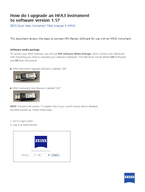
How do I upgrade an HFA3 instrumentto software version 1.5?ZEISS Quick Help: Humphrey® Field Analyzer 3 (HFA3)This document reviews the steps to connect HFA Review Software for use with an HFA3 instrument.Software media packageTo connect your HFA3 Software, you will use HFA Software Media Package, which contains two USB driveswith everything you need to complete your software installation. The USB drives will be labeled SW [Software] and UD [User Document].• HFA3 Instrument Upgrade Software is labeled “SW”• HFA3 Instrument User Manual is labeled “UD”NOTE: Proceed with version 1.5 update only if your current version device databasehas been backed up. Follow these steps.1. Go to Login screen.2. Log in as Administrator3. Select the Settings icon located in the Toolbar at the top of the screen.4. Navigate to the Maintenance screen to observe the Database backup interval set up for your device.Note: If no networking or backup location has been set up on your device, contact your IT Administrator to ensure the “Smart” backup is performed before proceeding with the software upgrade.5. I nsert the white USB drive with the SW label containing the software update into one of the USB connections located on the front of the HFA3 device.6. Navigate to Settings > Maintenance screen and select Perform update. A confirmation screen will appear.7. Select Yes to start Update Wizard.8. A popup screen will appear with the update. Highlight the update and select Run .9. T he “InstallShield Wizard for Humphrey Field Analyzer 3” screen will appear. Click Next to continue.Note: If the error message “Error copying NK bin” appears during installation, select OK and follow the instructions on the screen. Once the InstallShield Wizard has finished aborting installation, reboot the device and repeat the installation. This is an infrequent communication error that may occur at any point in the installation process. Follow the on-screen instructions through the rest of the software upgrade process.Note: If the following message appears, select Runin the popup and proceed.• T here may be brief sequences when the screen goes black for several seconds. Wait for the next on-screen prompt.• D o not touch the screen or type on the keyboard during the installation process except as directed by theon-screen prompts.• T here may be screens that show a progress bar. Occasionally, the progress bar will stop for several seconds,but the installation is still in progress.• T here will be several prompts for going to the next step or confirming a step. Respond to these promptsby using the touchscreen or the cursor driven by the keyboard or external mouse.• Select Finish from the InstallShield Wizard Complete screen.• T he background screen will turn black. A message will appear letting you know the instrument is goingto shut down and to start it again after shutdown. Click Close and wait for the instrument to shut down.Once shut down, remove the USB drive from the HFA3.0297S E R .10829 C Z -I /2019T h e c o n t e n t s o f t h i s r e f e r e n c e g u i d e m a y d i f f e r f r o m t h e c u r r e n t s t a t u s o f a p p r o v a l o f t h e p r o d u c t i n y o u r c o u n t r y . P l e a s e c o n t a c t y o u r r e g i o n a l r e p r e s e n t a t i v e f o r m o r e i n f o r m a t i o n . S u b j e c t t o c h a n g e i n d e s i g n a n d s c o p e o f d e l i v e r y a n d a s a r e s u l t o f o n g o i n g t e c h n i c a l d e v e l o p m e n t . H u m p h r e y a n d H F A a r e e i t h e r t r a d e m a r k s o r r e g i s t e r e d t r a d e m a r k s o f C a r l Z e i s s M e d i t e c , I n c . i n t h e U n i t e d S t a t e s a n d /o r o t h e r c o u n t r i e s . © 2019 C a r l Z e i s s M e d i t e c , I n c . A l l c o p y r i g h t s r e s e r v e d .• T urn the instrument ON by pressing the Power Button. The instrument will boot up and the screen may be black for several minutes. Wait until the InstallShield Wizard screen appears again. Allow the installer to complete the software update.• The InstallShield Wizard Complete screen will appear again. Click Finish to exit the Wizard.• You may now safely run the updated Humphrey Field Analyzer 3 Software.Refer to the HFA3 User Manual Instructions for Use for safe and effective operation of the instrument.Carl Zeiss Meditec AG Goeschwitzer Strasse 51–5207745 Jena GermanyCarl Zeiss Meditec, Inc.5160 Hacienda Drive Dublin, CA 94568USA。
CourseForge_SDS

CourseForge_SDSCourseForgeChris Schlechty, Kenneth Kuan, Scott Clifford, Guanyu Chu, Kansu Dincer, Sarah Tachibana, Andy Hou System Design Specification and Planning Document Draft 1.09April 25, 2007CSE 403 - CSRocks Inc.1. IntroductionCourseForge relies on a LAMP architecture. User and course information is stored ina MySQL database, which is accessed via AJAX XMLHttpRequest calls to PHPfunctions which make queries and convert the result to XML. The XML data isparsed and put on screen via Javascript/DOM modification. The database itself is populated using both data given to us by UW, as well as data collected using a Java screen scraper to parse professor ratings information.The modular breakdown of CourseForge follows: prior to interacting with thescheduling system, users must login. The Login module manages authentication, new user registration, and password recovery. The rest of the interface is representedthrough a Student module, which contains a VisualSchedule and a Search module.The VisualSchedule module manages individual Tabs, while the Search modulehandles queries and addition of courses to the schedule.2. Implementation view3. Design view - UML class diagram4. Process view – UML sequence diagrams5. Database Schema6. Design Alternatives and/or AssumptionsWe considered a few alternative representations and implementations of CourseForge before settling on the current version with our customer. These included: ? Information Gathering: We weren’t originally sure whether UW would provide us the course information necessary to implement our system, so weput thought into a screen scraper module that would periodically parse theonline course catalog. This would of course be more inconvenient, but for thetime being UW has given us a copy of a quarter’s worth of course information.We assume that, should CourseForge see widespread use, UW will continueto give us access to the necessary informationSchedule Representation: Given the limited screen estate available to us, we tried to think of other ways to represent the visual schedule. One was have a separate graph for each day. Times would be aligned horizontally, and eachrow would consist of a class, with a horizontal bar representing that class’duration. However, this view doesn’t allow for a holistic week view, andstudents are presumably already used to the day-per-column view used in thecurrent Visual Schedule, which we decided to stick with.General assumptions for this architecture include:We assume that Javascript, AJAX, and PHP will all support our object-oriented design. Javascript in particular is a more procedural language, andmay require extra effort to fit into the rest of the framework.We assume that Google Web Toolkit will provide us with coherent modules to piece together. GWT makes creating AJAX applications much easier, but depending on the resulting modules, it may be difficult to test and/or modifyin the future.1. Team StructureCourseforge will be divided into three main teams for the work up to the beta release: test team, AJAX team, and serverside/database team. There is member crossover between teams, and the serverside/database team will all be assimilated into the other teams once their work is complete.The test team is responsible for unit testing, user testing, and system testing,though everyone is expected to run prelim tests on their own code. This team is composed of: Kansu, Scott, Kenneth, and Andy. The AJAX team is responsible for java coding, HTML, CSS, and other UI-related features. It is composed of: Scott, Kansu, Andy, and Kenneth. Finally, the database team is responsible for the PHP coding and the setup/maintenance of the database. It is composed of: Chris and Guanyu. Chris is primarily database; Guanyu is primarily PHP.2. Project Schedule3. Risk Assessment1. Test Plan1.Unit test strategyo Unit tests will exercise the modules.o We will establish an artificial environment in which the module can live and then invoke the routines of the module. We will consider a test passedonly if the module satisfies its predetermined behavior.o Unit tests will be run every time a developer wishes to add/update the module to the repository.2.System test strategyo This type of testing will be used to test the functionality of the subsystems and the overall system.o The tests will highly depend on the use cases prepared for development.o System tests will be run once after every build./doc/4842452f0066f5335a81219f.html ability test strategyo With the usability tests, we aim to test the ease and efficieny with which our product can be used.o We will use both the prototypes and the actual product tested by real people from within the target audience.o Prototype testing will be (and to some extent has been) employed during the early design stages. Product testing will be accomplished once for theuser interface and once more with nearly full product functionality (beta?).4.The client-server nature of the product and the variety of tools used bring up anadditional challenge for the testing team. The scarcity of the tools available to test dynamic content such as JavaScript (AJAX in particular) on the client end is another obstacle. High source code coverage will be our goal.5.We will use bugzilla for bug tracking purposes. The developer / tester whoemploys the unit testing will post a bug report to notify the rest of the team about the bug.2. Documentation PlanThere are two types of documentation we would like to provide which correspond to strictly internal use and internal/external use.The internal documentation, which only developers will view, will consist of bug tracking, source control, and code comments. We will track bugs using Bugzilla, and we will use Subversion for source control.The code comments will be produced as modules and components are coded. The idea behind this is to write comments while the code written is fresh in the developers mind. This way, the developer may give better explanations of their code. Also, if another team member would like to edit or understand a component, having the comments their immediately allows for easier understanding and the team members do not necessarily have to explain their code verbally if something is not clear (provided the comments are adequate).The conventions that we will use for commenting is as follows:1.Header/Overview Description of Componentsa.Title of the component.b.Brief overview of the component.2.Function Explanationsa.Short explanation of functionality.b.List of parameters if applicable.c.Return value if applicable.3.Inline comments/doc/4842452f0066f5335a81219f.html ed at the developers discretion for clarity.The internal/external documentation will serve as a reference for both developers and users of the system. This will allow for a centralized source of documentation so that two forms of documentation (one for developers and one for users) will not need to be updated when changes are made.These documents will be written in the form of help guides for the CourseForge sys tem. The goal is to make them much like the “Help” guides you would find in any standard program these days. The documents would be accessible via a “Help” link on the system UI.The help guides will be formatted as follows:Finally, we will write an installation guide which will describe the process of installing our project on a personal server.。
VigorACS 2 Quick Start Guide
V i g o r A C S2U n i f i e d M a n a g e m e n t S y s t e mManual Version: 1.0Software Version: V2.3.1Date: August 17, 2018Table of Contents1. Platform for Windows 7 or 10 (5)1.1 Installation for Java (5)1.2 Installation for MariaDB (9)1.3 Installation for VigorACS 2 (14)1.4 StartMySQL/MariaDB Databse (23)1.5 Start VigorACS (23)2. Platform for Linux (25)2.1 Installation for MariaDB, Java and VigorACS (25)2.2 Start MySQL/MariaDB Databse (31)2.3 Start VigorACS (31)2.4 Edit VigorACS IP (31)3. Registering VigorACS 2 (32)3.1 Registration for VigorACS via Windows Platform (32)4. Configuration on CPE Device (37)4.1 Set ACS URL on CPE (37)4.2 Invoke Remote Management for CPE (39)4.3 Enable WAN Connection on CPE (40)5. Troubleshooting (42)1.P l a t f o r m f o r W i n d o w s7o r10Please follow the procedure listed below to install VigorACS 2 completely. The installation for different platforms might be different.T o start up the VigorACS, the normal procedure is listed as follows:(I)Installation for Java(II)Installation for MariaDB(III)Installation for VigorACS 2(IV)Start MySQL/MariaDB Database.(V)Edit VigorACS IP.(VI)Start VigorACS.Info VigorACS 2 can be operated only by a host with 64-bit operation system.1.1I n s t a l l a t i o n f o r J a v a1.Install Java by clicking “java-1.8.0-openjdk-1.8.1.151-1.b12…” to execute the installation.2.The first page will be shown as follows. Click Next to get into next page.3.Then, check “I accept the terms…” and click the Next button.4.In this page, optional features will be listed for you to specify the destination folder forJAVA driver installation. Choose the one you need and click Next.5.In the following page, just click Install.6.Wait for a while to install the required features.7.When the following page appears, the installation is completed. Click Finish to exit theinstalling program.1.2I n s t a l l a t i o n f o r M a r i a D B1.Install MariaDB by clicking “mariadb-10.2.10-winx64” (based on your PC condition) it toexecute the installation.2.When the welcome screen appears, please click Next for next step.3.On this dialog box, check the box of “I accept the terms….” and click Next.4.Select the way for the features to be installed. Then click Next.5.If you want to configure password for MariaDB server, please check Modify password… andtype the password. It depends on your request. Otherwise, simply click Next.6.Modify the default instance properties if required. Then click Next.7.On this dialog box, click Next.8.On this dialog box, click Install.9.The installation program starts to install required files for MariaDB to your computer. Waitfor several seconds.10.After finishing the configuration, please click Finish to exit the wizard.1.3I n s t a l l a t i o n f o r V i g o r A C S2It is time to install VigorACS main program. Follow the steps below.1.Click Setup to run VigorACS 2 setup wizard.2.When the following dialog appears, choose Local Database / Remote Database and clickNext.3.Select the directory that MariaDB being installed (done in 1.2) and click Next4.In this dialog box, choose Rebuild Database (for rebuilding the VigorACS database) orUpgrade Database (for upgrading the database). For the first time using, please choose Rebuild Database. Then click Next.5.Click Next. If you have configured MySQL/MariaDB previously and specified password for it,you have to type the password in this page and then click Next.6.Set the maximum memory and minimum memory. Click Next.7.Setup ACS HTTP and HTTPS port, we'll suggest using others port instead of default 80 and443 port to prevent conflict.Info The port number defined here will be used for opening VigorACS later.8.Determine the home path and click Next. The default directory used by this program isC:\Users. You can modify it if you want and please make sure the length of directory is not over 100 characters, otherwise you might encounter problem of VigorACS in installation.9.Determine the destination folder and click Next. The default directory used by thisprogram is C:\Program Files\VigorACS. You can modify it if you want and please make sure the length of directory is not over 100 characters, otherwise you might encounter problem of VigorACS in installation.10.Determine the start menu folder and click Next. The default directory used by thisprogram is VigorACS. You can modify it if you want and please make sure the length of directory is not over 100 characters, otherwise you might encounter problem of VigorACS in installation.11.In this dialog, check the box of “Create a desktop shortcut” for your necessity. Click Next.12.Now, the program is ready to install necessary features and files to your computer. Pleaseclick Install to start.13.Please wait for a while to complete the installation.14.While installing, the following screen will appear to show that MariaDB has been activated.Please wait for next dialog appearing.15.Now the program has completed the installation of VigorACS 2. Click Finish to exit it.1.4S t a r t M y S Q L/M a r i a D B D a t a b s eAfter installing VigorACS, install program will register MySQL/MariaDB to Windows Service.MySQL /MariaDB will startup automatically after installing VigorACS or rebooting system.Normally, you don't need to worry about this step on Windows. But if you find any problems on VigorACS, you should check mysql/mariadb first. Please go to Windows Service check theMySQL/MariaDB Service starts or not.1.5S t a r t V i g o r A C S1.Login VigorACS. Use a web browser and type “localhost:portnumber”. Note that the portnumber must be the one defined for HTTP and HTTPS port while installing VigorACS. Forexample, if HTTPS is defined as 8011, then the URL will be “localhost:8011”.2.The login page of VigorACS will be shown as the following. Please type “root” as user nameand “admin123” as password and type the authentication code. Then click Login.3.For the first time to access into the web user interface, a warning message appears first.Please click the Change password button to change the default password for networksecurity. If not, click Cancel to access into the web user interface of VigorACS and changethe password later.4.After clicking Login, main screen of VigorACS 2 will be shown as below.2.P l a t f o r m f o r L i n u xT o start up the VigorACS under Linux, please execute"/usr/local/vigoracs/VigorACS/bin/vigoracs.sh" instruction. A list of menu items will be shown as follows.1.Start mysql/mariadb2.Shutdown mysql/mariadb3.Start VigorACS4.Shutdown VigorACS5.Edit bind IP of VigorACS Server (please key in IP or server name)6.Set the Max. and Min. memory value of running java (it will be valid after restartingVigorACS)7.View the Max. and Min. memory value of running java8.exit2.1I n s t a l l a t i o n f o r M a r i a D B,J a v a a n d V i g o r A C SFollow the steps listed below to install VigorACS under Linux:1.Login Linux with root or the root privilege.2.Download the ACS installation tar.bz2 package and extract it via below command:#bzip2 -cd VigorACS_Unix_Like_xxxxxx_xxxxx.tar.bz2 | tar xvf -or#tar -jxv -f VigorACS_Unix_Like_xxxxxx_xxxxx.tar.bz23.Decompress the setup packagesbzip2 -cd VigorACS_Unix_Like_xxxxxx_xxxxx.tar.bz2 |tar xvf –4.Change the permissions mode of install.sh and uninstall.sh.chmod 755 install.shchmod 755 uninstall.sh5.Execute ./install.sh installation file.Please make sure you have /usr/bin/sh first. If you don't have /usr/bin/sh, please enter the command:#ln -s /bin/sh /usr/bin/sh6.The system will ask to create vigoracs, enter “y” to proceed.7.Next, the system will ask you to install xfonts-base and fontconfig, just enter “y” toproceed.8.Next, please select the item number which you want to execute. Note that VigorACSsupports Linux OS. The program will detect the system you have in your computer.(1) Install mysql/mariadb(2) Change root password and security configuration of mysql/mariadb(3) Install or Upgrade java(4) Install VigorACS(5) Upgrade VigorACS(6) Redirect the database path of VigorACS to remote host (7) Exitinput select num:InfoIf your computer has installed MariaDB and java previously, ignore theinstallation of them. Otherwise, install all the required items (MariaDB, Java and VigorACS) for your system. Item number 5 is used to upgrade VigorACS, so it is not necessary for you to execute for the first time of installation.9. Input 1 to install MariaDB first. Notice that it will setup blank as default password. You canchange the password by using the following command.#/usr/local/mysql/bin/mysqladmin--defaults-file=/usr/local/mysql/f -u root password 'newpassword'InfoThe password configured by the command above will be effective onlywhen there is no password set for database root before.Follow the instructions on the screen to finish the MariaDB installation.ter, input 2 to change root password and security configuration of mysql/mariadb.Info The password set in this step is used for VigorACS 2 to login database.11.Input 3 to install Java.Follow the instructions on the screen to finish the Java installation.12.Input 4 to install VigorACS. It is suggested to use ACS customized MariaDB database. Whenasked to enter MariaDB password, press “Enter” if you haven’t changed the password via the command. Then, confirm that TR-069 database has been installed successfully.Wait and follow the instructions on the screen to finish the installation.13. Now, input 6 to redirect the database path of VigorACS to remote host. For remotedatabase, please execute such step on remote host.14. Input 7 to finish and exit the installation.Info 1 Step 13 is required for establishing remote database only . You can ignore it while building local database.Info 2T o prevent port conflicts, we'll suggest that using other ports for HTTP and HTTPS instead of default 80 and 443.2.2S t a r t M y S Q L/M a r i a D B D a t a b s eAfter installing VigorACS, mysql/mariadb daemon has started. You can to see it using "ps-ef|grep mysql" instruction. Use the menu item 1 / 2 to start / shutdown mysql/mariadb.2.3S t a r t V i g o r A C SAfter installing VigorACS, access “/usr/local/vigoracs/VigorACS/bin”, execute “./vigoracs.sh”.Select item 3 to start VigorACS.If you ever reboot the machine after installing VigorACS, just select item 1 to startmysql/mariadb first. Then, select item 3 to start VigorACS.2.4E d i t V i g o r A C S I PWhen starting the VigorACS at first time on Linux, startup program will ask you input Server IP or input Enter key by using the IP address of the host. Once you input the IP address, VigorACS will keep it on startway.txt. Next time, if you want to change it, you can select item 5 to editstartway.txt using vi editor.3. R e g i s t e r i n g V i g o r A C S 2For the first time to activate VigorACS 2, the system will ask you to register VigorACS 2 onto DrayT ek MyVigor server . Refer to the following sections to register VigorACS 2 on differentplatforms.Info 1 While installing VigorACS, install program will register MySQL/MariaDB toWindows Service. MySQL/MariaDB will startup automatically after installingVigorACS or rebooting system. Normally , you don't need to worry about this step on Windows. But if you find any problems on VigorACS, you should checkmysql/mariadb first. Please go to Windows Service check the MySQL/MariaDB Service starts or not.Info 2After installing VigorACS, the software will startup automatically . Normally ,you don't need to worry about this step on Windows. But, if you find any problem on VigorACS, you could shut down VigorACS and start VigorACS again. 3.1 R e g i s t r a t i o n f o r V i g o r A C S v i a W i n d o w s P l a t f o r mBelow shows the steps to register VigorACS 2:1. Login VigorACS. Use a web browser and type “localhost:portnumber”. Note that the portnumber must be the one defined for HTTP and HTTPS port while installing VigorACS. For example, if HTTPS is defined as 8011, then the URL will be “localhost:8011”.2. The login page of VigorACS will be shown as the following. Please type “root” as user nameand “admin123” as password and type the authentication code. Then click Login.Info“root” and “admin123” are default settings.3. A License Error dialog appears as follows. Simply click Active.4. A login page for MyVigor web site will be popped up automatically . Type your account (username) and password in this page. Then, click Login.InfoIf you do not have any account, simply click Create an account now to create a new one for using the service provided by MyVigor web site.5.MyVigor will verify and authenticate if the user account you typed is allowed to access intothe web site. If yes, the following screen will appear.6.Type a nickname for VigorACS and click Add.7.After clicking Add, you can see the following screen. Click OK.8.You will get a device information page as shown below. If you are the new user of VigorACS,you can get a free charge of 30-day service of VigorACS. Simply click the Trial button.9.From the following screen, check the box of “I have read and accept the above….” andclick Next.10.In the page below, click Register.11.When the VigorACS License Information page appears, the service is ready for you to use.Click Login to ACS to use VigorACS service.12.The login page will appear as follows. Type the default settings of User Name (root) andPassword (admin123) and type the authentication code. Then, click Login.13.Now, the main screen of VigorACS will be shown as follows.4.C o n f i g u r a t i o n o n C P E D e v i c e4.1S e t A C S U R L o n C P ET o manage CPEs through VigorACS, you have to set ACS URL on CPE first and set username and password for VigorACS.1.Connect one CPE (e.g., Vigor2862 series).2.Open a web browser (for example, IE, Mozilla Firefox or Netscape) on your computer andtype http://192.168.1.1.3.Please type username and password on the window. If you don’t know the correctusername and password, please consult your dealer to get them. In this section, we takethe figures displayed on Windows as examples.4.Go to System Maintenance -> TR-069.•Please set URL as the following and type username and password for ACS server,for the connected CPE with authentication:http://{IP address of VigorACS}:80/ACSServer/services/ACSServlet•Please set URL as the following, for the connected CPE without authentication: http://{IP address of VigorACS}:80/ACSServer/services/UnAuthACSServlet•Please set URL as the following, for the connected CPE with authentication and the data transmission between CPE and VigorACS 2 with encryption (SSL).https://{IP address of VigorACS}:443/ACSServer/services/ACSServlet•Please set URL as the following, for the connected CPE without authentication but the data transmission between CPE and VigorACS 2 with encryption (SSL)https://{IP address of VigorACS}:443/ACSServer/services/UnAuthACSServlet5.Fill Username and Password for VigorACS 2 Server for authentication. Please enter as thefollowing:Username: acsPassword: password6.For the username and password of CPE client, it is not necessary for you to type them.7.Click Enable for Periodic Inform Settings.4.2I n v o k e R e m o t e M a n a g e m e n t f o r C P EYou have to make sure that the CPE device you want to connect supports VigorACS 2 features.Please consult your dealer if you have no idea in it.1.Suppose WAN IP of CPE device has been setup successfully. And you can access into Internetwithout difficulty.2.Login the device (e.g., Vigor2862) by web.3.Go to System Maintenance>>Management.4.Check Allow management from the Internet to set management access control.4.3E n a b l e W A N C o n n e c t i o n o n C P EYou have to make sure the CPE device you want to connect has been configured properly and can access into Internet.1.Login the device (e.g., Vigor2862) by web.2.Open WAN>>Internet Access.3.Choose Static or Dynamic IP as Access Mode and click Details Page for WAN2.4.The following web page appears. Click Enable and Specify an IP address. Enter correctWAN IP address, subnet mask and gateway IP address for your CPE. Then click OK.VigorACS 2 Quick Start Guide41InfoReboot the CPE device and re-log into VigorACS 2. CPE which has registered to VigorACS 2 will be captured and displayed on the home page of VigorACS 2.VigorACS 2 Quick Start Guide42 5. T r o u b l e s h o o t i n gWhen you try to invoke VigorACS 2 and get the following error message, please locate the file of “server .log ” from C:/Program Files/VigorACS/server/default/log and send the file to yourdealer for further assistance.For Linux system, please locate the file of “server .log ” from/usr/local/vigoracs/VigorACS/server/default/log/ and send the file to your dealer for further assistance.。
- 1、下载文档前请自行甄别文档内容的完整性,平台不提供额外的编辑、内容补充、找答案等附加服务。
- 2、"仅部分预览"的文档,不可在线预览部分如存在完整性等问题,可反馈申请退款(可完整预览的文档不适用该条件!)。
- 3、如文档侵犯您的权益,请联系客服反馈,我们会尽快为您处理(人工客服工作时间:9:00-18:30)。
Session A-T3-3 ADVANCED COURSE IN PROGRAMMABLE CONTROLS FOR ENGINEERINGTECHNOLOGYWm. Ted EvansUniversity of Toledo, Toledo, Ohio; Email:wevans@1. INTRODUCTIONProgrammable Logic Controllers (PLCs) have been found in industry since the early 1970’s and the application of PLCs has long been considered a required course for majors in Electrical Engineering Technology. A first course in PLCs is found in most 2 year programs, usually in the sophomore year. Content of a first course includes learning the PLCs instructions, some programming structures and the hardware one or more types of PLC. A second course, preferably taught in the senior year of a four-year technology program, should be structured to maximize the student’s employability. The content of this course is the topic of this paper.The content of the course should include applications of PLCs to both analog and digital processes. The analog portion should include an introduction to the PID algorithm from both from a theoretical and a practical point of view. Digital programs should include a number of more difficult programming applications.Software should be introduced that familiarizes the student with an array of software types needed in the manufacturing environment. Software for Human-Machine-Interface (HMI) development should be included. Also, software to successfully implement a network should be introduced. A list of potential projects including hardware will be discussed. Hardware types will be discussed including recommendations of equipment to purchase.2. COURSE DISTINCTIVESAfter a first course, the emphasis of the material should change dramatically. Emphasis in the first course was to acquire the tools necessary to build a PLC program for control of real time applications. The second course will deal with the aspects of building a system. The second course is intended to build an attitude that very difficult systems problems can be broken down into more manageable parts, each of which can be solved. A basic programming skill level is assumed for success in the second course. What is significantly more difficult than PLC programming is integration of all the components including programming into a complete system. Smart devices such as the Allen-Bradley PanelView operator interface or servo drive are devices used to interface to the PLC instead of push buttons, pilot lights and switches. ThePID instruction and several other more complicated programming instructions are some of the more difficult instructions to master. Listed below are several of the exercises used in this course.3. COMMUNICATIONA WITH PROCESSORSA procedure for attaching to SLC processors using DF-1 and DH-485 is used to demonstrate the multi-faceted approach that most PLC vendors use to attach a computer to the PLC. Methods used are intended to attach and set up the PLC for use as networked device. Also discussed are data highway types, approaches to communicate peer-to- peer and other communication topics in PLC communications.4. HUMAN-MACHINE-INTERFACEThe goal is to create an active interface between the PLC or group of PLCs and the operator. These are called Human-Machine-Interfaces or HMIs. Operators have been required to monitor and interpret much more information in the machine they operate than in the past. As a result, interfaces have become more complex. The operator may be called on to rapidly decide whether the machine is operating correctly or not. Alarms, machine modes, historical data, and real-time decision-making information are necessary to control many machines today.HMIs are divided roughly into two main groups. First is the dedicated HMI, a push-button, numeric data entry replacement device with little capability of storing data-base information for the machine. Typically these HMIs are stand-alone. Second is the HMI that is part of the data-base package used to store and retrieve process information from the machine. These HMIs usually run on a network of computers.Typical of the first group are products such as PanelView and PanelMate. Typical of the second group are products such as Fix Dynamics, Allen-Bradley RSView32 or WonderWare. For simpler applications, the PanelView will be selected. While it is not as sophisticated as the second, the process of building screens is similar. Also, the process of networking the processor to the HMI is similar.5. MSG BLOCKThe Message (MSG) instruction is also studied. A lab was devised that allows the student to send and receive messages between two or more PLCs. Block Transfer instructions are also used in some PLCs to communicate between various devices. Up to 64 words may be transmitted at a time using the Block Transfer Read (BTR) or Block Transfer Write (BTW) instruction. The remote device, however, is a device communicated to through remote I/O and using Allen-Bradley’s I/O files: M0 and M1 as opposed to the MSG instructions.6. PID BLOCKIn its simplest form, the PID block is used as a single block with no input contacts and surrounded by only two Scaling Blocks (Scaling with Parameters – SCP) in the mid-level rack mount SLC 5/03 processor from Allen-Bradley. The SCP blocks are configured to retrieve a numerical value from the analog input channel, linearly scale the input and move the resultant value to the PID block.HMI displays are used to allow the operator to run the process from the display. To run the PID successfully, several parameters should be displayed either to set the process in motion or to adjust the process once it is in motion.A ramp block is a function block that is added in front of a PID block to change the setpoint (SP) over a period of time instead of immediately. It is constructed in the PLC diagram to increment from the old SP to the new SP in increments of 1. More sophisticated ramp blocks allow the ramp rate to be set by an operator or engineer.When the PID block is switched from manual to auto, the function responds to the SP presently available to the block. If the process is sensitive to sudden changes in PID output, the program should include logic to give the output a signal matching the present flow when the block is in manual. This is commonly referred to as bumpless transfer.Processes are described using flow diagrams. Symbols for diagrams are defined by the organization - Instrumentation, Systems, and Automation Society (ISA). Letter codes are written in circles representing various devices that control a process.7. ASCII BLOCKSOnly the ASCII WRITE (AWT) and ASCII READ (ARD) will be used to demonstrate communication between serial devices. The AWT or AWA instruction is appropriate for the Write instruction. Since no appended characters need be appended to the string, the AWT instruction may be preferred. The ASCII blocks demonstrate communication between PLCs and devices such as bar code readers or weigh scales.8. FAULT RECOVERY INSTRUCTIONSChapter 12 of the SLC 500 and MicroLogix 1000 Instruction Set Reference Manual is dedicated to understanding interrupts in the PLC. Four major types of routines are introduced. They are the User Fault, Selectable Timed Interrupt, Discrete Input Interrupt and I/O Interrupt.The User Fault Routine is used to protect the processor from shutting down when a fault occurs. The other three routines interrupt the processor scan and run a program to accomplish a particular high priority task.When a recoverable or non-recoverable user fault occurs, the processor goes to Status Table location S:29 and reads a number corresponding to a program file handling the fault. If the fault is a recoverable fault, the program in the file can correct the problem and clear the fault bit, allowing the processor to fully recover from the fault. Of course, if the problem occurs again, the fault will occur again.9. STEPPER AND SERVO CONTROLOne SLC 5/03 was used to control an automatic storage and retrieval system of pallets. This is commonly referred to as an ASRS. Two different motion control cards were used to control the horizontal and vertical motion of the positioning belts used to move the pallet-extracting device. Although an engineer would not select two different types of control cards to install in such an installation, the two cards selected were a stepper control card and a servo control card. Specifically, the stepper control card was the SLC Stepper Controller Card (1746-HSTP) and the servo card was the SLC Servo Controller Card (1746-HSRV).When starting the program development of the stepper motor, the first object should be to control the drive manually. If possible, the drive should be controlled with a simple test program to give the engineer simple control of the axis. In this case, no program is necessary. Entry of the configuration and command words is seen as all that is necessary to control the drive manually. To configure the SLC Servo Module, data is written to the M0 file, not the Output Data File as was the case with the stepper controller card. Use a copy file to transfer data to the M0 file.10. DEVICE-NET NETWORKDeviceNet is a relatively easy I/O network to install and configure. It will be discussed in part by using a manual from Allen-Bradley, the DeviceNet Starter Kit Installation Manual. DeviceNet is an extension of CanBus. DeviceNet is an easy-to-implement network that uses CanBus as well as additional software drivers to implement industrial networks. The DeviceNet Starter Kit is a good point to introduce the capabilities of an industrial network to students.11. CONTROLOGIXThe ControlLogix platform is suited for the high-end application while the CompactLogix platform is more suited for the lower-end application. Costs are also comparatively lower for the CompactLogix platform.Each of these processor types uses RSLogix 5000 software and can be programmed in a similar manner. Assigning of tags and building of programs is similar through the product line. Creation of tags is one of the first differences found to be a major change from the SLC programming experience. As discussed in the Logix5000 Quick Start Manual, tags are no longer automatically assigned but given names only as the programmer (you) assign them. Tag databases are just that, a data base. With the creation of a new tag, the entire function of that tag is defined. The name is the name used above the contact. The type is a bit, integer, or other type used in the definition of how the data is actually stored.12. SAFETYAllen-Bradley, Jokab and Banner Engineering are only some of a long list of safety equipment manufacturers. Use of information from their catalogs gives an insight into proper design of a circuit as it pertains to safety in an industrial setting13. OTHER PLCsPLCs have moved in many different directions over the last few years. One direction is toward a standardization of languages of the various PLCs so projects can more easily be moved between different hardware platforms. This standardization has become the IEC 1131 specification.14. NETWORKS AND PROTOCOLSIt is not enough to know that everything uses Ethernet and thus be able to ‘get by’ when implementing a modern control network using Ethernet. Knowledge of multitasking is needed as well as a background pertaining to proper configuration of each device on the network on the plant floor. The same Ethernet cable is now be able to transmit office or business data as well as process monitor and control data and embedded device data.15. AUTOCADD ELECTRICALGenerating of electrical schematic drawings can be a very manual task. Either AutoCAD or other graphic package is most often selected and the drawings are generated using a symbol library purchased from a source or created by the user.16. SUMMARYToday, PLC programming involves engineering hours and the money necessary to generate the engineering hours for the job. Companies do not have an infinite supply of either money or hours to appropriate to any project. Programming intelligently is a high priority in today’s engineering environment.Some of the projects listed in the paper are very difficult when studied thoroughly. Two or three weeks of intense work should be allowed to master various aspects of these projects. It is very humbling for some students to even be required to re-learn the basics of logging on to the PLC in order to be able to program on-line.The goal of the second course in PLCs is to aid the student in the interview process to find a good job. In order to do this, the student must be informed and interested in the potential job. If the job includes PLC programming, courses such as the one outlined in this paper should aid in that task.REFERENCESSample of Existing Texts on Programmable Logic ControllersDavid A. Geller, (2005). Programmable Controllers Using the Allen-Bradley SLC-50 Family, Pearson, 2nd Ed.John R. Hackworth, Fred D. Hackworth, (2004). Programmable Logic Controllers – Programming Methods and Application, PearsonHugh Jack, (2003). Automating Manufacturing Systems with PLC’s, unpublishedThomas Kissel, (1986). Understanding and Using Programmable Controllers, PrenHallS. Brian Morriss. (2000). Programmable Logic Controllers, PrenHallJon Stenerson , (2004). Programming PLCs Using Rockwell Automation Controllers, Pearson Jon Stenerson, (2004). Fundamentals of Programmable Logic Controllers, Sensors, and Communications, 3rd Ed., PrenHallFred Swainston, (1992). A Systems Approach to Programmable Controllers, DelmarJohn Webb, Ronald A. Reis, (1999). Programmable Logic Controllers, Principles and Applications, 2nd Ed, PrenHallSystems Manuals used for the Lab Experiences:PanelBuilder 32 Software, Getting Results, Allen-BradleySLC Modular Processors, User Manual, Allen-BradleyDeviceNet Starter Kit Installation Manual, Alley-BradleySLC 500 Instruction Set Reference Manual, Allen-BradleyLogix5000 Quick Start Manual, Allen-Bradley。