PCM-9362_DS(04.22.10)
【解决】mp3芯片24bit解决方案
【关键字】解决mp3芯片24bit解决方案篇一:常用解码芯片介绍解码芯片介绍:(排名不分先后)很多烧友在苦苦寻找哪款解码器最适合自己,那么下面就我一些所知作一下介绍,以便于大家选择,当然也期望高手光临指导,我也在探索研究中。
以排名第一的PCM1794/PCM1794,为100分,对解码芯片进行打分。
比较常见的高端解码器芯片有下面那一些:以下几款只要能设计好,调音好,做好,都可以出最好的声音,效果难分难解,各有特色,各有所长所好。
芯片的指标并不代表声音的好坏,关键看周围其他电路设计,决定了最后输出声音的品质。
下面的声音解说,都是按照“音乐剑神”的设计调音能力能达到的最高水平。
不包括也不保证,其他品牌用同样的芯片,能达到同样效果。
我觉得听了及格的没几款。
如果发现和我们类同介绍,必是盗版。
多片DAC芯片并联能提高多少效果:很多客户问,那2片并联或4片并联到底能提高多少效果呢?拿4片16BIT的并联,和1片24BIT的,区别多少?并联使用DAC可提高等效比特数,提高转换精度,还原音乐的厚度感和力度感增强。
当DAC并联使用时,信噪比、动态范围都会提高,而失真度将会减小,各种误差也被平均化而降低。
并联的方法有很多种,风格稍有不同。
大体上说:2个18 bit DAC并联后的转换精度相当于19 bit,4个20 bit DAC并联后转换精度相当于23 bit ,而8个20 bit DAC并联后转换精度相当于24 bit,等等。
PCM1704等24 bit DAC出现之前,高档数字音响的24 bit转换精度就是利用多个DAC并联方法得到的。
所以4个16 bit的并联,相当于19 bit效果。
从人耳声音听感上来说,区别不可能象技术指标数字上的差距那么大。
24BIT的技术指标要比20BIT高16倍,即2的4次方,24BIT的技术指标要比16BIT的高1024倍。
所以2并联从技术指标上来,20BIT的就相当于21BIT的了,提高100%,但声音效果是提高10%左右。
pcm编译码实验总结

PCM编译码实验总结介绍在通信系统中,信息传输是一个至关重要的环节。
为了使数字信号能够在传输过程中保持完整和准确,需要对其进行编码和解码。
PCM(脉冲编码调制)编译码是一种常用的数字信号编码和解码方法,本实验旨在通过实际操作,深入理解和掌握PCM编译码的原理和应用。
实验目的•探究PCM编码的原理和工作方式•了解PCM解码的过程和实施方法•理解编码参数对信号质量的影响•学会通过MATLAB等工具进行PCM编译码实验实验器材与软件实验器材•个人电脑•信号发生器•数字示波器•学习开发板软件•MATLAB•C语言开发环境实验步骤PCM编码部分1.生成待编码的模拟信号(正弦波、方波等),并用MATLAB进行波形展示2.设置编码参数(量化等级、采样频率等),编写MATLAB代码实现PCM编码3.使用数字示波器观测编码后的数字信号,验证编码结果的准确性和完整性PCM解码部分1.通过学习开发板将编码后的数字信号发送到计算机2.使用C语言编写解码程序,实现PCM解码过程3.对解码后的数字信号进行重建,并用数字示波器观测其波形,验证解码结果的准确性和完整性参数调整与分析1.改变编码参数,如量化等级和采样频率,观察编码和解码结果的变化2.对比不同编码参数下的信号质量,分析其优缺点和适用范围结果与分析PCM编码结果通过MATLAB生成的波形图和数字示波器观测结果可以看出,PCM编码可以将模拟信号转换为数字信号,并实现信号的准确传输。
编码后的数字信号保持了原始信号的基本特征,但是数据量大大减小,便于传输和处理。
PCM解码结果通过C语言解码程序实现的PCM解码过程可以将编码后的数字信号还原为与原始信号相似的模拟信号。
解码结果经过数字示波器的观测,与原始信号具有良好的一致性,证明了PCM解码的准确性和有效性。
参数调整与分析结果通过改变编码参数,我们发现不同的量化等级和采样频率对信号质量有明显的影响。
较高的量化等级和采样频率可以增加信号的分辨率,提高信号的保真度,但数据量也相应增大。
新核心网开站步骤(精)

关于阿朗CDMA的IPBH基站的整合步骤主要目的:因目前新局使用的基站使用IPBH和以前的frame relay方式不同,添加了阿朗的路由交换机7750设备代替了5E同基站连接。
根据新局现场(软件是R31版)的测试经验,总结基站部分的内容,方便SUB-C工程师查阅和尽快上手,也为客户准备技术文档。
步骤简介:根据IPBH基站的特点,主要三个部分步骤:一,基站硬件安装调测二,基站和7750确认传输路由的配合步骤三,基站的数据添加一,基站硬件安装调测1)基站硬件安装完毕2) 基站用RMT调测基站背板参数,把Frame 转为PPP模式,主要是在RMT/boot memory parameter窗口中/trunk group controller parameter简称TGCP和initial link configuration parameter简称ILCP/ recall成RMT自带的配置文件/自己电脑中的RMT目录/config/1bts/IEH/BMP/中根据URC功能配置分1X和EVDO两种:1X的URC是/Voice/URC-URCII/E1/IPBH-Voice/CDM has its owner E1s/TGCP-CDM(1-5-9-13)-IPBH-E1-v4和/Voice/URC-URCII/E1/IPBH-Voice/CDM has its owner E1s/ILCP-CDM(1-5-9-13)-IPBH-E1-v4EVDO的URCII是EVDO/URC-URCII/E1/PPP-EVDO/CDM has its owner E1s/TGCP-CDM(2-6-10-14)-PPP-E1-v4和EVDO/URC-URCII/E1/PPP-EVDO/CDM has its owner E1s/ILCP-CDM(2-6-10-14)-PPP-E1-v4二,基站和7750确认传输路由的配合步骤1,7750加数据需要的条件:1)基站RCS号2)基站传输编号,主要基站每条传输E1是第几个155M(7750连接40条155M)的第几个时隙(每条155M有63个时隙),需要电信客户传输部门提供3)基站现场的E1先自环并和7750工程师配合断开测试确认E1正常2,在基站现场确认得到IP地址,网线连接到基站,telnet 192.168.168.16(第一块URC)或192.168.168.32(第二块URC),执行下面的命令:用户名:lucent 密码:password自动出现背板参数击入:mlpppShow检查是否有MY IP和Primary DNS IP及Secondary DNS IP,这三个IP是7750配置的数据,必须全部是有IP地址的,如为0.0.0.0则基站信令不会起来的,需要联系7750工程师确认或添加数据。
VS1053b音频解码器编码器

VS1053b是单片Ogg Vorbis/MP3/AAC/WMA/MIDI音频解码器,及IMA ADPCM编码器和用户加载的Ogg Vorbis编码器。
它包含了一个高性能、有专利的低功耗DSP处理器内核VS_DSP4、工作数据存储器、供用户应用程序和任何固化解码器一起运行的16KiB 指令RAM及0.5KiB多的数据RAM、串行的控制和输入数据接口、最多8个可用的通用I/O引脚、一个UART、并有一个优质的可变采样率立体声ADC(“咪”、“线路”、“线路+咪”或“线路*2”)和立体声DAC、和跟随的一个耳机功放及一个公共电压缓冲器。
特性●Ogg Vorbis解码;MPEG1&2音频阶层III(CBR+VBR+ABR);阶层I和II可选;MPEG4/2AAC‐LC(+PNS),HE‐AAC V2(级别3)(SBR+PS);WMA4.0/4.1/7/8/9所有特性注1(profiles)(5‐384kbps);WAV(PCM+IMA ADPCM);通用MIDI1/SP‐MIDI格式0的文件●用软件插件进行Ogg Vorbis编码(2007第四季可用)●“咪/线路”的输入信号可实现IMA ADPCM编码(立体声)●支持MP3和WAV的数据流●EarSpeaker空间效果注2处理●低音和高音控制●只用一个单独的12..13MHz时钟运作●也可以使用一个24..26MHz时钟运作●内建PLL时钟乘法器●低功耗运作●芯片内建高质量和通道间无相位误差的立体声DAC●过零交叉注3(Zero‐cross)侦测和平滑的音量调整●立体声耳机驱动器可以驱动一个30Ω的负载●安静的电源通断功能●可扩展外部DAC的I2S接口●分离的模拟、数字、IO供电电源●供用户代码和数据使用的片内RAM●用于控制和数据的串行接口●可以作为从模式的辅助处理器使用●特殊应用可使用SPI FLASH存储器引导●可用于调试的UART接口●可用软件增加新功能和提供最多8个GPIO●符合RoHS无铅标准的封装(绿色环保)。
PCM-3362_Startup_Manual_Ed1_FINAL

PCM-3362 Startup ManualBefore you begin installing your card, please make sure that the following materials have been shipped: 1 x PCM-3362 SBC 1 x SAT A data cable (p/n: 1700071000)1 x SAT A power cable (p/n: 1703150102)1 x Keyboard/Mouse cable (p/n: 1703060053)1 x Y cable for KB/MS extension (p/n: 1700060202)1 x Ethernet RJ-45 conn. cable (p/n: 1700017863)1 x VGA cable (p/n: 1700000898)1 x USB cable (p/n: 1703100260) (bracket type with two USB ports)1 x RS-422/485 COM cable (p/n: 1703040157)1 x RS-232 COM cable (p/n: 1701200220)1 x A TX power cable (p/n: 1700002332)1 x A T power cable (p/n: 1700003491)1 x Startup Manual (this manual)1 x CD-ROM (Manual, Driver, Utility)If any of these items are missing or damaged, please con-tact your distributor or sales representative immediately. Model No.List DescriptionPCM-3362N-S6A1E Intel Atom N450 PC/104-PlusSBC, VGA, LVDS, LAN, USB,SAT A and on-board flash Optional Accessary 1 x heatspreader(p/n:1960047106T001)Note: Acrobat Reader is required to view PDF files. Ac-robat Reader can be downloaded at: /Prodindex/acrobat/read-step.html (Acrobat is a trademark of Adobe).••••••••••••••PCM-3362 PC/104-plus SBC w/Intel® Atom N450, VGA, LVDS, LAN, USB2.0, SATA, and on-board flash Startup ManualStandard SBC functionsCPU: Intel Atom N450 processor, up to 1.67 GHzSystem memory: supports Double Data Rate (DDR) DDR2 667 SDRAM up to 2 GBNote: PCM-3362 does not support DDR2 533 SDRAM 2nd cache memory: 512 KB on the processor System chipset: Intel® ICH8M BIOS: AMI 16 Mbit Flash BIOSWatchdog timer: 255 levels timer intervalExpansion interface: PC/104-Plus (ISA and PCI bus)Battery: Lithium 3 V/210 mAHPower management: ACPI supportedSerial ATA: One Serial AT A2 interface, speed up to 300MB/sFlash: On board 2 GB flash (IDE interface)Serial ports: T wo serial RS-232 ports, one RS-422/485 portsKeyboard/mouse connector: Supports one standard PC/AT keyboard and a PS/2 mouseUSB: Four USB 2.0 ports compliant universal serial bus portsHigh definition audio: PCM-3362 can provide audio function with the optional audio extension module PCA-AUDIO-HDA1E and specific audio cableVGA/TTL InterfaceController: Integrated graphic core of Embedded en3.5+ technologyVRAM: 224 MB shared system memory Output interfaces:– VGA: Supports up to SXGA 1400 x 1060 @ 60 Hz – LVDS: Singe channel 18-bit LVDS up to WXGA 1366 x 768– Dual display: CRT + LVDS, supports extended mode and clone modeEthernet InterfaceSupports Single 10/100/1000 Mbps Ethernet networkingController: Intel® 82567VOS SupportThis board supports Win 7, Win XP , Win CE and Win XPe For further information about OS support in your PCM-3362, please visit the Adventech website:, or contact your technical support center.Mechanical and EnvironmentalDimensions: 96 x 90 mm (3.8” x 3.5”)Power supply type: AT/ATX•••••••••••••••••••••••• SpecificationsPacking ListFor more information on this and other Advantech products, please visit our website at:/eplatformFor technical support and service, please visit our support website at:/support This manual is for the PCM-3362 Series Rev. A1.Part No. 2006336200 Printed in China1st EditionDecmber 20092 PCM-3362 Startup ManualPower requirement: +5 V ± 5%, +12 V ± 5% (Optional), 5 V only, 12 V optional for PC104 add on card and LCD inverter)Power consumption: (Geode LX800, 512 MB DDR333) - Power on Load: +5 V@ 1.79 A, +12 V@ 0.02 A - Max load: +5 V@ 2.37 A, +12 V@ 7 mA - Idle mode: +5 V@ 2 A, +12 V@ 5 mA Power consumption Conditions:- Test software: Maxpower + 3DMark 2005- Power on - Boot: Measure the maximum current value of between system power on and boot-up to O.S.- Max. load: Measure the maximum current value which system under maximum load (CPU: Top speed , RAM & Graphic: Full loading)- Idle mode: Measure the current value when system in windows mode and without running any programOperating temperature: 0 ~ 60° C (32 ~ 140° F) ( opera-tion humidity: 40°C @ 85% RH Non-Condensing)Weight: 0.85 kg (reference weight of total package)Jumpers and ConnectorsThe board has a number of jumpers that allow you to con-figure your system to suit your application.The table below lists the functions of each of the jumpersand connectors.•••••Warning! To avoid damaging the computer, always turn offthe power supply before clearning CMOS.SpecificationsJumpers and ConnectorsPCM-3362 Startup Manual 3Figure : PCM-3362 Location Connectors & Jumpers(component side)Figure 2: PCM-3362 Location Connectors & Jumpers(solder side)Software InstallationThe CD disc contains a driver installer program that will guide you through the installation of various device drivers needed to take full advantage of your CPU card.Caution! The computer is provided with a battery-poweredReal-time Clock circuit. There is a danger of explosion if the battery is incorrectly replaced. Replace only with same or equivalent type recommended by the manufacturer. Discard used batteries according to manufacturer’s instructions.Safety InformationThis device complies with the requirements in Part 15 of the FCC rules. Operation is subject to the following two conditions:This device may not cause harmful interference.This device must accept any interference received, including interference that may cause undesired opera-tion.1.2.Locating Connectors and JumpersJumpers and ConnectorsPCM-3362 Startup ManualFigure 3: PCM-3362 Mechanical Drawing (component side)Figure : PCM-3362 Mechanical Drawing (solder side)Mechanical Drawings。
智能融合cSoC:多通道FFT共享处理器使用FPGA纤维说明书

Application Note AC381February 20121© 2012 Microsemi Corporation SmartFusion cSoC: Multi-Channel FFT Co-Processor Using FPGA FabricTable of ContentsIntroductionThe SmartFusion ® customizable system-on-chip (cSoC) device integrates FPGA technology with a hardened ARM ® Cortex™-M3 processor based microcontroller subsystem (MSS) and programmable high-performance analog blocks built on a low power flash semiconductor process. The MSS consists of hardened blocks such as a 100 MHz ARM Cortex-M3 processor, peripheral direct memory access (PDMA), embedded nonvolatile memory (eNVM), embedded SRAM (eSRAM), embedded FlashROM (eFROM), external memory controller (EMC), Watchdog Timer, the Philips Inter-Integrated Circuit (I 2C),serial peripheral interface (SPI), 10/100 Ethernet controller, real-time counter (RTC), GPIO block, fabric interface controller (FIC), in-application programming (IAP), and analog compute engine (ACE).The SmartFusion cSoC device is a good fit for applications that require interface with many analog sensors and analog channels. SmartFusion cSoC devices have a versatile analog front-end (AFE) that complements the ARM Cortex-M3 processor based MSS and general-purpose FPGA fabric. The SmartFusion AFE includes three 12-bit successive approximation register (SAR) ADCs, one first order sigma-delta DAC (SDD) per ADC, high performance signal conditioning blocks, and comparators. The SmartFusion cSoCs have a sophisticated controller for the AFE called the ACE. The ACE configures and sequences all the analog functions using the sample sequencing engine (SSE) and post-processes the results using the post processing engine (PPE) and handles without intervention of Cortex-M3 processor.Refer to the SmartFusion Programmable Analog User’s Guide for more details.This application note describes the capability of SmartFusion cSoC devices to compute the Fast Fourier Transform (FFT) in real time. The Multi Channel FFT example design can be used in medical applications, sensor network applications, multi channel audio Spectrum analyzers, Smart Metering, and sensing applications (such as vibration analysis).This example design uses the Cortex-M3 processor in the SmartFusion MSS as a master and the FFT processor in the FPGA fabric as a slave. All three of the SmartFusion cSoC A2F500’s ADCs are used for data acquisition. The example design uses Microsemi’s CoreFFT IP and the advanced peripheral bus interface (CoreAPB3). A custom-made APB3 interface has been developed to connect CoreFFT with the MSS via CoreAPB3. The Cortex-M3 processor uses the PDMA controller in the MSS for the data transfer and thus helps to free up the Cortex-M3 processor instruction bandwidth.A basic understanding of the SmartFusion design flow is assumed. Refer to Using UART with SmartFusion - Microsemi Libero ® SoC and SoftConsole Flow Tutorial to understand the SmartFusion design flow.Introduction . . . . . . . . . . . . . . . . . . . . . . . . . . . . . . . . . . . . . . . . . . . . . . . . 1Design Overview . . . . . . . . . . . . . . . . . . . . . . . . . . . . . . . . . . . . . . . . . . . . . 2Design Description . . . . . . . . . . . . . . . . . . . . . . . . . . . . . . . . . . . . . . . . . . . . 2Implementing Multi Channel FFT on EVAL KIT BOARD . . . . . . . . . . . . . . . . . . . . . . . . . 7Running the Design . . . . . . . . . . . . . . . . . . . . . . . . . . . . . . . . . . . . . . . . . . . . 8Conclusion . . . . . . . . . . . . . . . . . . . . . . . . . . . . . . . . . . . . . . . . . . . . . . . . 9Appendix A – Design Files . . . . . . . . . . . . . . . . . . . . . . . . . . . . . . . . . . . . . . . 10SmartFusion cSoC: Multi-Channel FFT Co-Processor Using FPGA Fabric2Design OverviewThis design example demonstrates the capability of the SmartFusion cSoC device to compute the FFT for multiple data channels. The FFT computation is a complex task that utilizes extensive logic resources and computation time. In general, for N number of channels, N number of FFT IP’s are needed to be instantiated, which in turn utilize more logic resources on the FPGA. A way to avoid this limitation is to use the same FFT logic for multiple input channels.This design illustrates the implementation of a Multichannel FFT to process multiple data channels through a single FFT and store FFT points in a buffer. The FFT computes the input data read from each channel and stores the N-point result in the respective channel’s allocated buffer. The channel multiplexing is done once each channel buffer has been loaded with the FFT length.Computing frequency components for a real time data of six channels is described in this application note. For sampling the input signals the AFE is used and the complex FFT computation is implemented in the fabric of the SmartFusion cSoC device. The Cortex-M3 processor in the MSS of the SmartFusion cSoC handles the buffer management and channel muxing.Figure 1 depicts the block diagram of six channel FFT co-processor in FPGA fabric.Design DescriptionThe design uses CoreFFT for computing the FFT results. You can download the core generator for CoreFFT at /soc/portal/default.aspx?r=4&p=m=624,ev=60.The design example uses a 512-point and 16-bit FFT. A custom-made APB3 interface has been developed to connect CoreFFT IP with the MSS’s FIC. The CoreFFT output data is stored in a 512x32FIFO within the fabric. The FIFO status signals are given in Table 1 on page 3. The status signals indicate that FFT is ready to receive data and data is available in the output of FIFO. These status signals are mapped to the GPIOs in the MSS. The Cortex-M3 processor can read the GPIOs to handle flow control in the data transfer process from the MSS to CoreFFT.Figure 1 • Multi Channel FFT Block DiagramDesign Description3Figure 2 shows the block diagram of logic in the fabric with custom-made APB3 bus.The data valid signal (ifiD_valid) is generated in custom logic whenever the master needs to write data into the input buffer of the FFT to process through the APB3 interface. The FFT_IP_RDY signal indicates the status of the input buffer of the FFT. If the input buffer is full, the FFT_IP_RDY goes low. The master can read the FFT_IP_RDY signal to get the FFT input buffer status. The FFT generates the processed data with a data valid signal (ifoY_valid). The processed data is stored in the FIFO. When FIFO is not ready to receive output data, it can stop the data fetching from the FFT by pulling down the ifiRead_y signal. The status signal FFT_OP_RDY is used to indicate to the master that processed data is available in the FIFO. FFT_OP_RDY goes High whenever processed data is available in the FFT output buffer.The master can use AEMPTY_OUT or EMPTY_OUT to determine whether the FIFO is empty and all the processed data has been read. Refer to the CoreFFT Handbook for more details on architecture and interface signal descriptions.Three ADCs are configured to have two channels, each channel with 100 ksps sampling rate. The external memory is used for input and output buffers. For each channel, one input buffer having length double to the length of FFT i.e. 1024 words and one output buffer having length equal to the length of FFT i.e. 512 words are used. After each channel's input buffer has 512 points required for the full length of the FFT, each channel, one after the other, streams its points from the FIFO through the FFT. During the FFT computational period, the sampled data values of each channel are stored in the second half of the input buffer. Once the FFT computations for the First half of input buffer completes then the points in the second half of the input buffer will be streamed to FFT. This operation utilizes a ping-pong method. The Cortex-M3 processor is used for data management, that is, buffering the sampled points and data routing or muxing of these values to the FFT computation block. Sampling of the real time data is done by the ACE. The PDMA handles the data transfer between the external SRAM (eSRAM) buffers and CoreFFT logic in FPGA fabric.Figure 2 • CoreFFT with APB Slave InterfaceTable 1 • FIFO Status Signals with DescriptionsSignalDescription FFT_IP_RDYFFT is ready to receive the Input from the master processor FFT_OP_RDYProcessed data is ready in output buffer of FFT AEMPTY_OUTOutput FIFO is almost empty EMPTY_OUT Output FIFO is emptySmartFusion cSoC: Multi-Channel FFT Co-Processor Using FPGA Fabric4Figure 3 shows the implementation of multi channel FFT on the SmartFusion cSoC device.Hardware ImplementationThe MSS is configured with an FIC, clock conditioning circuit (CCC), GPIOs, EMC and a UART. The CCC generates 80 MHz clock, which acts as the clock source. The FIC is configured to use a master interface with an AMBA APB3 interface. Four GPIOs in the MSS are configured as inputs that are used to handle flow control in data transfer from MSS to FFT coprocessor. The EMC is configured for Region 0as Asynchronous RAM and port size as half word. The UART_0 is configured for printing the FFT values to the PC though a serial terminal emulation program.ADC0, ADC1, and ADC2 are configured with 12-bit resolution, two channels and the sampling rate is set to approximately 100 KHz. Figure 4 on page 5 shows the ACE configuration window.Figure 3 • Implementation of Multi Channel FFT on the SmartFusion cSoCDesign Description5The APB wrapper logic is implemented on the top of CoreFFT and connected to CoreAPB3. A FIFO of size 512*32 is used to connect to CoreFFT output.CoreAPB3 acts as a bridge between the MSS and the FFT coprocessor block. It provides an advanced microcontroller bus architecture (AMBA3) advanced peripheral bus (APB3) fabric supporting up to 16APB slaves. This design example uses one slave slot (Slot 0) to interface with the FFT coprocessor block and is configured with direct addressing mode. Refer to the CoreAPB3 Handbook for more details on CoreAPB3 IP .For more details on how to connect FPGA logic MSS, refer to the Connecting User Logic to the SmartFusion Microcontroller Subsystem application note.The logic in the FPGA fabric consumes 18 RAM blocks out of 24. We cannot use eSRAM blocks for implementing CoreFFT as the transactions between these SRAM blocks and FFT logic are very high and are time critical.Figure 5 on page 6 illustrates the multi channel FFT example design in the SmartDesign.Figure 4 • Configure ACESmartFusion cSoC: Multi-Channel FFT Co-Processor Using FPGA Fabric6Table 2 summarizes the logic resource utilization of the design on the A2F500M3F device.Software ImplementationThe Cortex-M3 processor continuously reads the values from ACE and stores the values into the input buffers. If the first 512 points are filled then the processor initiates the FFT process. In the FFT process,the input buffers are streamed one after other to the CoreFFT with the help of PDMA. Using another channel of PDMA the output of FFT is moved to the corresponding channel output buffers.During the FFT process the Cortex-M3 processor stores the sampled values into the second half of the input buffers. Once the FFT process completes the first half of input buffer, then the second half of the input buffer are streamed to CoreFFT.Figure 5 • SmartDesign Implementation of Multi Channel FFTTable 2 • Logic Utilization of the Design on A2F500M3FCoreFFTOther Logic in Fabric Total Ram Blocks14418 (75%)Tiles 78424718313 (72.1%)Implementing Multi Channel FFT on EVAL KIT BOARD7The CALL_FFT(int *) application programmable interface (API) initiates the PDMA to transfer input buffer data to the FFT in the fabric. Before initiating PDMA it checks for FFT whether or not it is ready to read the data. The CALL_FFT(int *) API also checks if the output FIFO is empty so that all the FFT out values have been already read. When the input buffer has points equal to the full length of FFT, then it will be called.The Read_FFT() API initiates the PDMA for reading the FFT output values from FIFO in fabric to the corresponding output buffer. After reading all the values it calls the CALL_FFT() API with the next channel buffer to compute the FFT for next channel. This is done for all channels. After completion of FFT computation for all channels, if the continuous variable is not defined, it will print the FFT output values on the serial terminal. When FFT_OP_READY interrupt occurs then this API will be called.The GPIO1_IRQHandler() interrupt service routine occurs on the positive edge of FFT_OP_READY signal. It calls Read_FFT() API. This interrupt mechanism is used to read the sample values continuously while computing the FFT.If continuous variable is defined, then the FFT is computed without any loss of data samples. If #define continuous line is commented then after every completion of FFT computation of all channels the FFT output is printed on serial terminal. The printed values are in the form of complex numbers.The ping-pong mechanism is used for input data buffer to store the samples continuously. For each channel the input buffer length is double of the full FFT length. While computing the FFT for the first half of the buffer, the new sample values are stored in the second half of the input buffer and while computing the FFT for second half of buffer, the new sample values are stored in first half of the input buffer.Customizing the Number of ChannelsYou can change the design depending on your requirement. Configure the ADC (Figure 4 on page 5)with the required number of channels and required sampling rate. In SoftConsole project change the parameter value NUM_CHANNELS according to the ADC configuration. Edit the main code for reading ADCs data into buffers according to ACE configuration.Throughput CalculationsThe actual time to get 512 samples with 100 ksps is 5.12 ms. Each channel is configured to 100 ksps, so for every 5.12 ms we will have 512 samples in the input buffers.The actual time taken to compute the FFT for each channel is the sum of time taken to transfer 512points to CoreFFT, FFT computation time, and time to read FFT output to the output buffer.•Total time for computing FFT = (time taken to receive 512 data + computational latency for 512points + time taken to store 512 data) = 512*5 + 23292 + 512*5 =28412 clks •Time to compute FFT for 6 channels = 28412*6 = 170472 clksTime to compute FFT for six channels is 2.1309 ms (If CLK is 80 MHz). It is less than half the sample rate of 5.12 ms.If only one channel is configured with maximum sampling rate (600 ksps) then time to get 512 samples with 600 ksps is 0.853 ms. Time to compute FFT for these 512 samples is 0.355 ms. If you configure three ADCs with maximum sampling rate (1800 ksps) then time to compute the FFT for these three channels will be 1.065 ms which is higher than the sampling time. In this there is a loss of some samples.The design works fine up to 1440 ksps.Implementing Multi Channel FFT on EVAL KIT BOARDTo implement the design on the SmartFusion Evaluation Kit Board the FFT must be 256 point and 8 bit because the A2F200 device has less RAM blocks and logic cells. The ADC channels must be selected for only ADC0 and ADC1. Figure 6 on page 8 shows the implementation of multi channel FFT on the SmartFusion cSoC (A2F200M3F) device.SmartFusion cSoC: Multi-Channel FFT Co-Processor Using FPGA Fabric8Table 3 summarizes the logic resource utilization of the design with 256 points 8-bit FFT on A2F200M3F device.Running the DesignProgram the SmartFusion Evaluation Kit Board or the SmartFusion Development Kit Board with the generated or provided *.stp file (refer to "Appendix A – Design Files" on page 10) using FlashPro and then power cycle the board.For computing continuous FFT values for the all six signals sampled through the ADCs, uncomment the line #define continuous in the main program. The FFT output values are stored in the rdata buffer. This buffer is updated for every computation of FFT.For printing the FFT values on serial terminal (HyperTerminal or PuTTy), comment the line #define continuous in the main program.Figure 6 • Implementation of Multi Channel FFT on the SmartFusion Evaluation Kit BoardTable 3 • Logic Utilization of the Design on A2F200M3F DeviceCoreFFTOther Logic in Fabric Total Ram Blocks718 (100%)Tiles 3201853286 (66%)Conclusion9Connect the analog inputs to the SmartFusion Kit Board with the information provided in Table 4.Invoke the SoftConsole IDE, by clicking on Write Application code under Develop Firmware in Libero ®System-on-Chip (SoC) project (refer to "Appendix A – Design Files") and launch the debugger. Start HyperTerminal or PuTTY with a baud rate of 57600, 8 data bits, 1 stop bit, no parity, and no flow control.If your PC does not have the HyperTerminal program, use any free serial terminal emulation program such as PuTTY or Tera Term. Refer to the Configuring Serial Terminal Emulation Programs Tutorial for configuring the HyperTerminal, Tera Term, or PuTTY .ConclusionThis application note describes the capability of the SmartFusion cSoC devices to compute the multi channel FFT. The Cortex-M3 processor, AFE, and FPGA fabric together gives a single chip solution for real time multi channel FFT system. This design example also shows the 6-channel data acquisition system.Table 4 • SettingsChannelEvaluation Kit Development Kit Channel 173 of J21 (signal header)ADC0 of JP4Channel 274 of J21 (signal header)ADC1 of JP4Channel 377 of J21 (signal header)77 of J21 (signal header)Channel 478 of J21 (signal header)78 of J21 (signal header)Channel 585 of J21 (signal header)Channel 686 of J21 (signal header)Figure 7 • FFT Output Data for 1 kHz Sinusoidal Signal on PUTTYSmartFusion cSoC: Multi-Channel FFT Co-Processor Using FPGA Fabric10Appendix A – Design FilesThe Design files are available for download on the Microsemi SoC Product Groups website:/soc/download/rsc/?f=A2F_AC381_DF.The design zip file consists of Libero SoC projects and programming file (*.stp) for A2F200 and A2F500.Refer to the Readme.txt file included in the design file for directory structure and description.51900249-0/02.12© 2012 Microsemi Corporation. All rights reserved. Microsemi and the Microsemi logo are trademarks of Microsemi Corporation. All other trademarks and service marks are the property of their respective owners.Microsemi Corporation (NASDAQ: MSCC) offers a comprehensive portfolio of semiconductor solutions for: aerospace, defense and security; enterprise and communications; and industrial and alternative energy markets. Products include high-performance, high-reliability analog and RF devices, mixed signal and RF integrated circuits, customizable SoCs, FPGAs, and complete subsystems. Microsemi is headquartered in Aliso Viejo, Calif. Learn more at .Microsemi Corporate HeadquartersOne Enterprise, Aliso Viejo CA 92656 USAWithin the USA: +1 (949) 380-6100Sales: +1 (949) 380-6136Fax: +1 (949) 215-4996。
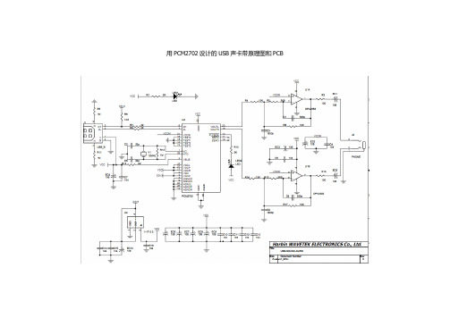
用PCM2702设计的USB声卡带原理图和PCB
【特性脚功能】
管脚
名称
类型
功能描述
1
XTI
IN
晶体振荡器输入
2
VDDC
-
时钟产生器电源(3.3V)
3
DGNDC
-
时钟产生器数字地
4
VDD
-
数字电源(3.3V)
5
DGND
-
数字地
6
D+
IN/OUT
USB差分输入/输出正极
7
D-
IN/OUT
USB差分输入/输出负极
22
VCC
-
模拟电源+5V
23
VOUTL
OUT
左ቤተ መጻሕፍቲ ባይዱ道模拟输出
24
AGNDL
-
左通道模拟地
25
VCCL
-
左通道模拟电源+5V
26
AGNDP
-
锁相环电路模拟地
27
VCCP
-
锁相环模拟电源+5V
28
XTO
OUT
晶体振荡器输出
8
VBUS
IN
USB总线电源(该管脚绝对不消耗USB总线电源)
9
DGNDU
-
USB收发器的数字地
10
PLYBCK
OUT
回放指示标志,低电平有效(低电平:回放;高电平:等待)
11
SSPND
OUT
暂停指示标志,低电平有效(低电平:暂停;高电平,工作)
12
ZERO
OUT
低电平为正常;高电平为0
13
TEST3
IN
测试管脚3,和数字地相连
APM32E103xCxE 基于 Arm Cortex-M3 内核的 32 位微控制器说明书
功能描述 .....................................................................................................................20
系统架构 ........................................................................................................................................21 4.1.1 系统框图 ..................................................................................................................................................21 4.1.2 地址映射 ..................................................................................................................................................22 4.1.3 启动配置 ..................................................................................................................................................22
- 1、下载文档前请自行甄别文档内容的完整性,平台不提供额外的编辑、内容补充、找答案等附加服务。
- 2、"仅部分预览"的文档,不可在线预览部分如存在完整性等问题,可反馈申请退款(可完整预览的文档不适用该条件!)。
- 3、如文档侵犯您的权益,请联系客服反馈,我们会尽快为您处理(人工客服工作时间:9:00-18:30)。
Optional Accessories
(MIO interface is optional by request)
Part No. MIO-6254 MIO-6255 MIO-6260 1700016161 1700016141 Description MIO module w/DVI, S-Video, Audio MIO module w/2 x Cardbus MIO module w/4 x USB, 2 x COM, 1 x LAN AT Power cable, 2 x 6P to 3 x 4P 10 cm AT power cable, 2 x 6P to 2 x 10P 10 cm
Software APIs:
LVDS GPIO H/W Brightness Watchdog Backlight SMBus CPU Speed System Monitor On/Off Throttling
USB
LAN
COM1
VGA
Utilities:
BIOS flash Monitoring eSOS Flash Lock Embedded Security ID
Packing List
Part No. Description PCM-9362 SBC Startup Manual Utility CD mini Jumper pack ATX Power Cable SATA Cable PS/2 cable COM2 IDE D-SUB 20 cm cable USB 2 x 5P-2.0 12 cm W/BKT cable Audio Cable LPT IDE 26P D-SUB 25 cm cable SATA 10 cm Power cable Quantity
9689000002 1700000265 1700006291 1703060191 1701140201 1703100121 1703100152 1700260250 1703150102
x1 x1 x1 x1 x1 x2 x1 x1 x1
Embedded OS/API
Embedded OS/API Win XPE Software API Part No. 2070009030 2070009031 205E362010 Description XPE WES2009 Luna Pier V4.0 ENG XPE WES2009 Luna Pier V4.0 MUI24 SUSI 3.0 SW API for PCM-9362 B: 20091117 XP
Memory
Display
Expansion
Power
Environment Physical Characteristics
3.5" Single Board Computers
All product specifications are subject to change without notice Last updated : 22-April-2010
LPT COM1/3/4: RS232 COM2: RS-232/422/485
Ordering Information
Model PCM-9362NC-S6A1E PCM-9362N-S6A1E PCM-9362D-S6A1E PCM-9362NZ-1GS6A1E CPU Atom N450 Atom N450 Atom D510 Atom N450 Power Input 5V 12 V 12 V 12 V CRT LVDS 1 1 1 1 1 1 1 1 Giga LAN1 Yes Yes Yes Yes Giga LAN2 Yes Yes Yes Yes Audio SATAII HD HD HD HD 2 2 2 2 USB 2.0 6 6 6 6 Mini-PCIe CF LPT RS-232 RS-232/422/485 1 1 1 1 1 1 1 1 1 1 1 1 3 3 3 3 1 1 1 1 Thermal Solution Passive Passive Active Passive Operating Temperature 0 ~ 60° C 0 ~ 60° C 0 ~ 60° C -20 ~ 80° C
Online Download /products
Value-Added Software Services
Software API: An interface that defines the ways by which an application program may request services from libraries and/or operating systems. Provides not only the underlying drivers required but also a rich set of user-friendly, intelligent and integrated interfaces, which speeds development, enhances security and offers add-on value for Advantech platforms. It plays the role of catalyst between developer and solution, and makes Advantech embedded platforms easier and simpler to adopt and operate with customer applications.
Specifications
CPU Processor System Front Side Bus Frequency L2 Cache System Chipset BIOS Technology Max. Capacity Socket Chipset VRAM Graphics Engine LVDS VGA Dual Display Speed Ethernet Audio WatchDog Timer Storage Rear I/O Controller Connector Chipset CompactFlash SATA Serial Ethernet VGA USB USB Serial Internal I/O Parallel (LPT) KB/Mouse GPIO I2C Mini PCI Express MIO 160 Power Type Power Supply Voltage Power Consumption (Typical) Power Consumption (Max, test in HCT) Power Management Battery Operational Non-Operational Dimensions (L x W) Weight Intel Atom Processor, N450 Single Core 1.66 GHz Intel Atom Processor, D510 Dual Core 1.66 GHz 667 MHz 1.66 GHz 512 KB/1 MB Intel N450/D510 + ICH8M AMI 16 Mbit Flash BIOS DDR2 667 MHz 2 GB 1 x 200-pin SODIMM Intel Atom N450/D510 1.66 GHz Optimized Shared Memory Architecture up to 224 MB system memory Intel Gen 3.5 DX9, MPEG2 Decode in HW Embedded Gen3.5+ GFX Core LVDS: Single channel 18-bit LVDS up to WXGA 1366 x 768 Intel Atom N450 Single Core up to 1400 x 1050 (SXGA) Intel Atom D510 Dual Core up to 2048 x 1536 CRT+LVDS 10/100/1000 Mbps LAN1 Intel 82567V Giga LAN LAN2 Intel 82583V Giga LAN RJ-45 on LAN1,LAN2 Realtek ALC888, High Definition Audio(HD),Line-in, Line out, Mic-in Output System reset, Programmable 1 ~ 255 sec Supports CompactFlash Card TYPE I/II (Primary Master IDE Channel) 2 1 (COM1 supports RS-232) 2 (10/100/1000 Mbps) 1 2 4 x USB 2.0 ports 3 x COM ports COM3/COM4 supports RS-232 COM2 supports RS-232/422/485 1 1 8-bit GPIO 1 1 1 (Optional by request) AT/ATX AT: 5 V or 12 V, ATX: 5 V, 5 V sb (12 V is optional for LCD inverter and add on card) AT: 12 V, ATX: 12 V, 5 V sb PCM-9362NC-S6A1E: 5 V : 2.31 A PCM-9362N-S6A1E: 12 V : 0.87 A PCM-9362D-S6A1E: 12 V : 0.91 A PCM-9362NC-S6A1E: 5 V : 2.36 A PCM-9362N-S6A1E: 12 V : 1.01 A PCM-9362D-S6A1E: 12 V : 1.17 A APM, ACPI Lithium 3 V/210 mAH 0 ~ 60° C (32 ~ 140° F) Operating: 0 ~ 60° C (32 ~ 140° F) (Operating humidity: 40° C @ 85% RH non-condensing) Non-Operating: -40° C ~ 85° C and 60° C @ 95% RH non-condensing 146 x 102 mm (5.7" x 4") 0.85 kg (1.87 lb), weight of total packageHDຫໍສະໝຸດ G: CI & LCI