AR-410 操作手册
乐科LW420A 410A 任意波形发生器用户手册说明书
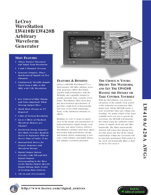
F EATURES& B ENEFITS LeCroy's LW420B WaveStation™ is a dual-channel, 400 MS/s arbitrary wave-form generator (A WG) that brings together high performance with the flexibility and capability needed to quickly generate long, complex wave-forms. WaveStation offers more than just great technical specifications. It provides a high level of functionality and ease of use while eliminating many of the traditional obstacles ofA WGs.Building on over 11 years of experi-ence in the design and manufacture of high-performance digital storage oscil-loscopes and signal sources, LeCroy's WaveStation combines innovative signal processing, high-performance design, and human factors engineering to pro-vide a truly intuitive and highly interac-tive arbitrary waveform generator. T HE C HOICE IS Y OURS:S PECIFY T HE W AVEFORM, AND L ET T HE LW420BH ANDLE THE D ETAILS OR T AKE C ONTROL Y OURSELF With the WaveStation, you need no awareness of the sample clock period or the particular reconstruction filter being used. All the LW420B needs is your waveform’s time and voltage rela-tionships. No matter which of the many available tools you use to specify the waveform, the LW420B will generate the output using the optimum combi-nation of sample clock rate and filter bandwidth. The filters automatically selected will assure that aliasing does not take place and that all the timing relationships within the waveform will be precisely maintained. Full control of the clock and bandwidth filters is there for those who need it.LeCroyWaveStationLW410B/LW420BArbitraryWaveformGeneratorLW410A/420A AWGSR EAL -TIME W AVEFORM M ANIPULATION L ETSY OU Q UICKLY C ONTROL T HE W AVESHAPE —E ASILY AND I NTERACTIVELY —W HILE V IEWING ON THE I NTERNAL CRT D ISPLAYSelect a section of the waveform using the time cursors, then select one of a set of waveform manipulation opera-tions (e.g. move feature, delay, ampli-tude) and turn the knob! That is how easy it is to continuously modify all or part of a waveform. Time shifts, as small as 100 ps, amplitude variations on a peak, or changes in signal dura-tion are instantly reflected in the output signal. Margin testing or characteriza-tion, with the most complex wave-forms, has never been so easy.W AVEFORM C REATION H AS N EVER B EEN E ASIERWaveforms can be selected from libraries of traditional functions or application specific waveforms. They can also be created using equations or imported from external sources such as oscilloscopes, or from computer pro-grams and simulator output files. Once waveforms are created or captured,they can be further modified using internal waveform (array) math pro-cessing. The waveform math functions include basic arithmetic operations,smoothing, integration, differentiation,and convolution.The highly developed waveform edit-ing capability uses advanced signal processing to provide bandlimited cut,paste, insert and offset operations with minimal editing artifacts. Single sample resolution, further simplifying wave-form creation, is allowed since wave-forms are not constrained to 8 sample multiples as with most other A WGs.To simulate real-world signals, the internal, asynchronous, wide-band noise generator is easily used to add controlled amounts of noise to your signals—simply dial in the noise level as a percentage of your signal’s ampli-tude. A real timesaver is that if youvary the signal’s amplitude, the signal-to-noise ratio is maintained.F LEXIBLE W AVEFORM I MPORT A ND T RANSFERPull waveforms directly from most digi-tal scopes; Connect a GPIB cable between the LW420B and your digital oscilloscope. Select your scope from a list of commonly available models and begin importing waveforms.Waveforms of up to 1 Mpoints in ASCII or from programs such as MathCad,MATLAB, PSPICE, IQSIM, TOPSIM and others can be imported from the floppy drive. You can also use a shareware program from LeCroy to convert your files to DIF format and transfer directly over the GPIB to the LW420B.When importing or transferring files,you have the choice of over sampling or importing the points exactly as they are. Once in the WaveStation, all the modification, editing and math tools can be used to put the waveform in the shape you need for your task.F AST S WITCHG ROUPS EQUENCE I NCREASES T EST F LEXIBILITY ANDM INIMIZES T EST T IMELeCroy’s Fast Switch Group Sequence capability enables you to switch between many different pre-loaded waveforms in less then 11 ms.Waveforms will continually play until a sequence advance is received from the front panel or a remote command.Choose to auto advance from sequence to sequence or choose to jump to the nth sequence in the group. Generate a continuous output of a sequence selected from the group, or use the external trigger input to initiate a burst or single shot of the selected sequence.D IGITAL O UTPUT O PTIONThe Digital Output option provides 8-bit TTL and ECL digital outputs corre-sponding to the current value of the Channel–1 analog output. The latched digital data is held for the duration of the sample clock. The digital data,including the sample clock and its complement, are available via rear-panel connectors. The special digital editing mode is useful for creating and editing byte wide data patterns orselected bits and the standard “cut and paste” tools available for analog wave-forms can also be used.400 MS/S M AXIMUM C LOCK R ATE , 1 M POINT W AVEFORMS , ANDS YNTHESIZER T IMEBASE W ITH T WO P HASE -S YNCHRONIZED C HANNELSA maximum sample rate of 400MS/s,up to 1Mbyte of waveform memory, a precise timebase, and single point reso-lution gives you the power you need to generate the most demanding, com-plex stimuli. The timebase combining 3 ppm accuracy and 1 ppm/year stabil-ity assures that the waveforms you test your systems with next year will be the same as the ones you use today. Low single sideband phase noise and a 1 Hz frequency resolution over a con-tinuous 6 kHz–400 MHz range provide the flexibility and capability needed to generate even the most complex and demanding waveforms.F ULLY I NTEGRATED AWG I NCLUDESH IGHP ERFORMANCE P ROCESSOR ,I NTERNAL H ARD D ISK D RIVE , A ND B UILT -IN 9I NCH CRTWaveStation provides all the power needed to work with long and com-plex waveforms. A built-in hard disk drive, a 486 processor, up to 24 Mbytes of RAM, and a large internal mono-chrome VGA display make the LW420A a fast, responsive instrument ideally suited for the interactive graphical operations required in a high-perfor-mance A WG.S I G N A L S O U R C E SLW410A/420A AWG SG ENERATOR M ODEStandard Function Waveforms Sine, 1 Hz–100 MHz Square, 1 Hz–50 MHz Triangle, 1 Hz–25 MHz Ramp, 1 Hz–25 MHzPulse, (period) 20 ns - max. memory DCFrequency Sweep, Linear / Log Multitone, 1–10 tones,1 Hz–100 MHzSpecial Waveform Generation Mode IMD - Intermodulation distortion test waveform: Select center frequency, 1-15 tone pairs, tone spacing, resolu-tion, offset from center frequency.A RBITRARY F UNCTIONSWaveform CreationInteractive Graphical editor on internal 9” diagonal CRT—8.5” viewable.Standard FunctionsSine, Square, Triangle, Ramp, Pulse, DCEquation EditorWaveform (array) Math Waveform Import From Digital Oscilloscope Floppy Disk Feature Time Resolution:100 ps @ 400 MHz Available memory:256 k/ch standard 1 Mpoint optionalS EGMENTED W AVEFORMSMinimum segment length:64 points Maximum segment length:Up to available memory (1 Mpoint with memory option installed).Segment length resolution:1 point Number of links: 512 for 256k memory 2048 for 1M memoryW AVEFORM O UTPUT C HARACTERISTICSOutput channels:LW410A – 1 Channel LW420A – 2 ChannelOutput Impedance:50 Ω, ±5%DC Accuracy:2% ±40 mV >500 mV 2% ±15 mV <500 mV Vertical resolution:8 bits Minimum output voltage: 10 mV p-p into 50 ΩMaximum output voltage: 10 V p-p into 50 ΩOffset voltage range:±5 V into 50 Ω.The output voltage (signal + offset)must be in the range ±5 V into 50Ω.Offset voltage resolution:0.05% of full scaleOutput bandwidth:100 MHz (-3dB)(widest bandwidth)Total harmonic distortion:For sinusoidal output of <5 V p-p; < -45 dBc (-50 dBc typical) forfrequencies: <1MHz < -35dbc (< -45 dBc typical) forfrequencies: 1 MHz–20 MHz < -25 dBc (< -40 dBc typical) forfrequencies: >20MHz–50 MHz, predominantly 2nd harmonic Spurious & non-harmonic distortion:< -60 dBc for frequencies <1 MHz Signal-to-noise ratio:>40 dB (-45 typ-ical) for output amplitudes >100 mV @0 offsetTransition times:5.0 ns, 10%–90% at widest bandwidth.Overshoot and ringing:<8% of step size max. 3% typicalSettling time: <50 ns to within 2% of step size at widest bandwidth.Inter-channel crosstalk:<1%Ch 1 to Ch 2 skew:<1 ns for identical waveforms in each channel (widest bandwidth).Output protection:±20 VOutput filtering: Gaussian filters with the following cutoff frequencies can be selected; 100 MHz , 10 MHz, 1 MHz ,100 kHz , 10 kHzS AMPLE C LOCK C HARACTERISTICS(with internal 10 MHz reference)Sample Clock: 6 kHz–400 MHz Resolution: 1 HzAccuracy:<3 ppm over operating tem-perature range.Stability:aging <1 ppm/yearSSB Phase Noise: < -90 dBc/Hz @ 10KHz offset for a 10 MHz sine wave at the outputT RIGGERINGC HARACTERISTICSTrigger slope: Positive or Negative Trigger input impedance:50 Ω±5%Threshold range:±2.5VThreshold resolution: 20 mV Threshold accuracy:100 mV Threshold sensitivity:50 mV p-p Minimum pulse width:5 ns Protection: ±5 VT RIGGER M ODESContinuous:Runs continuously Single: Outputs 1 repetition of the waveform for each trigger received.Triggers received while the waveform is still running are ignored.Burst:Outputs the selected waveform a programmable number of times in response to a trigger. The maximum number of repetitions for a burst is 4,095. Triggers received while the burst is running are ignored.Gated:The waveform starts on theleading edge of the gate signal and stops on completion of the waveform cycle occurring at the trailing edge of the gate signal.T RIGGER D ELAYMinimum delay time:35 ns ±3.5 ns +5 sample clocks (fixed)Maximum delay time:10 s at highest clock rate to 100k s at lowest clock rate.Delay resolution:1 sample clock.Delay is in units of seconds. When operating from the front panel, the res-olution is set in increments of the sam-ple clock period.Delay accuracy:Same as sample clock + minimum delay time.Delay jitter:1 sample clock.T RIGGER S OURCESManual:Front panel push-button.External:Front panel BNC connector.GPIB:A trigger command may be issued over the GPIB bus.M ASS S TORAGE3.5” 1.44 MB DOS format floppy drive 400 MB internal hard disk drive.A UXILIARY I NPUTSExternal 10 MHz reference:Rear panel BNC connector for input of an external reference clock. 400 mV p-p to 5 V p-p into 50 Ω.A UXILIARY O UTPUTS10 MHz reference: ±3 ppm accuracy Amplitude (high): 1.6V into 50 Ω.Amplitude (low): 0.2V into 50 Ω.Markers: Select Edge or Clock Edge: 1 bit memory—set up to 128edge transitions—ECL or TTL levels Clock: Frequency up to one half the sample clock rate.Protection:Outputs protected to ±5 V.Channel 1 Digital Output Optional:8 bits and clock with TTL and ECL logic levels available simultaneously. Noise In: From rear panel BNC connectors.H ARD C OPY O UTPUTSSupported Printers include:Epson MX/FX Epson LQ HP LaserJet II HP ThinkJetP ROGRAMMABILITYGPIB IEEE 488.2 compatible.Compliant with SCPI programming lan-guage. Capable of initiating and con-trolling waveform transfer from digital oscilloscopes by simply connecting a GPIB cable (no computer required).M ECHANICALDimensions:14.92”W x 7.67”H x 19.58”D (37.9 cm x 19.5 cm x 49.7 cm)Weight:27.6 lbs (12.5 kilograms)E NVIRONMENTALTemperature:5º to 35º full specifica-tions; 0º to 40ºC operating;-20º to 70ºC non-operating.Humidity:10% to 90% relative, non-condensingP OWER :Autosensing90-132/180-250 V AC 47-63 Hz4 amps @ 115 V AC(20 amps cold start surge)2 amps @ 230 V AC(40 amps cold start surge)Warranty:One YearS I G N A L S O U R C E S。
AR-410操作手册

绪 言承蒙惠顾,购得AR-410打印机。
在使用本机前,请细阅这本用户手册,以便能正确使用。
并且请妥善保存这本手册,万一有不了解或故障时,这本手册会带给您很大的帮助。
AR-410打印机是得实集团与日本西铁城公司合作开发、生产的多用途9针80列重负荷平推式票据打印机。
AR-410具有超强的金属机械结构,特有的票据厚度自适应打印设计,摩擦和链式两种平推式进纸,打印速度高达68汉字/秒,打印针寿命3亿次,600万字符长寿命耐用大色带,GB18030中文大字符集硬字库,使AR-410在硬件方面别具特色。
在软件方面,AR-410秉承了得实系列打印机的高性能、高兼容性,可兼容所有STAR和EPSON 打印机,方便的自动撕纸功能及参数设置功能是得实打印机的特色。
打印机针调整和断针自动补偿功能是得实打印机的专利技术。
AR-410易用、耐用、功能强大、用途广泛、性能价格比特高,是商业、财税、零售、餐饮等行业打印各类票据的极佳选择。
本产品信息如有更改,恕不另行通知。
本资料仅供参考。
除中国现行法律法规规定,得实集团不承担任何由于使用本资料而造成的直接或间接损失的责任。
得实集团保留最终解释权。
目录第1章安装打印机...................................1-11.1开箱和检查......................................1-11.2放置打印机......................................1-21.3打印机部件......................................1-31.4安装和拆卸色带盒................................1-51.5打印机和主机连接................................1-81.6连接电源.......................................1-101.7安装打印驱动程序...............................1-11第2章纸的安装和使用...............................2-12.1选纸............................................2-12.2使用单页纸......................................2-22.3使用链式纸......................................2-3第3章控制面板.....................................3-13.1按钮及其指示灯..................................3-13.2开机功能........................................3-43.3组合功能........................................3-7第4章参数设置.....................................4-14.1如何进行参数设置................................4-24.2系统设置........................................4-34.3纸张设置........................................4-64.4接口设置.......................................4-104.5标准模式设置...................................4-114.6用户自定义页长.................................4-144.7双向测试及纵向校正.............................4-164.8打印针自动调整设置.............................4-194.9打印针补偿设置.................................4-204.10恢复出厂设置...................................4-22第5章票据通设置和使用.............................5-15.1 票据通设置......................................5-25.2 票据通的使用....................................5-3第6章用户调整设置.................................6-16.1 链式装纸页首调整................................6-16.2 摩擦装纸页首调整................................6-26.3 撕纸位置调整....................................6-3第7章故障和保养...................................7-17.1 故障处理........................................7-17.2 保养与维护......................................7-6第8章规格.........................................8-18.1 打印机规格......................................8-18.2 接口接头引脚....................................8-48.3 字符集..........................................8-88.4 控制码摘要表...................................8-148.4.1 标准模式和24针图像仿真控制码摘要表............8-14附录1:电子信息产品污染控制的说明.....................9-1安全规范使 用 注 意 事 项为了避免受到电击和伤害及防止损坏打印机,在接上电源之前,务请注意以下重要事项:仔细阅读操作手册等说明文件。
AR-400+ 操作手册
3
企业公开信息:
1. 售后服务请致电全国各地得实服务网点电话,或拨打: 400-810-9998(手机) 800-810-9998(免费) 2. 产品能耗: 产品使用状态 工作时 操作模式功率(休眠) 待机功率(关闭) 最大能耗 30W 3.2W 0.1W 最小能耗 10W
a. 本产品符合 GB25956-2010 《打印机、 传真机能效限定值及能效等 级》一级能效等级最高要求。 b. 打印机停止使用 5 分钟(默认出厂设置) ,即自动切换到节能模 式(详见第 4 章) 。 c. 只有当产品无任何外接输入电源时,才能实现零能耗。 3. 在换气不畅的房间中长时间使用或打印大量文件时, 建议用户适时 换气。 4. 如果用户需对产品性能升级或更换模块, 请来电咨询, 我们将给您 详细解答。 5. 当您弃置达到使用寿命年限的针式打印机或其原装耗材时, 我们建 议您将废弃产品返还给本公司或全国各地的得实服务网点, 由得实 集团作统一处理,以保护生态环境。 6. 本产品能使用含 70%回收纤维的再生纸进行打印。在不影响使用 的情况下,为节约资源,请选择使用再生纸;请选择双面打印。 7. 产品与电网电源的断开装置: 通过拔掉电源线插头能彻底切断产品 与电源电网的连通。
4
第1章 安装打印机
1.1 开箱和检查
打开纸箱,对照下图检查箱内部件和附件是否齐全。如果有任何 部件遗失,请与卖方联系。 注意:使用之前,请先取出打印头固定板及打印头固定珍珠棉,保留 原包装箱及缓冲材料,以备以后使用。
*机器出厂时, 送纸旋钮未安装于机器上, 请从缓冲材料上取出并安装。
附件
安装打印机
1-1
1.2 放置打印机
在安装打印机之前,首先要确定一个合适的地方放置打印机。 这里“合适的地方”是指: 平放在工作台上。 避免将打印机置于过热、过度潮湿和灰尘过多的地方。 接上稳定电源,避免与电冰箱之类大功率或有干扰的电器同一电 源。 关掉打印机电源开关后,才能拔插电源线插头,打印机应尽可能 放置在接近插座的地方,便于使用。 打印机必须放置在走纸空间足够的地方。 如果用打印机并行接口连接,必须确保电缆长度在 2 米范围内; 用 RS-232C 连接,可选 SPC-32K 转换器,连接距离可在 15 米以 内。
所еди电信AT-AR410系列模块型分支机构路由器数据表说明书

A T -AR410 SERIESModular Branch Office RoutersDatasheet | RoutersA T -AR410Modular Branch Office RouterA T -AR410SSecure Modular Branch Office RouterWirespeed E1/T1 IPsec VPN OperationWith full Layer 3 multi-protocol routingcombined with wirespeed VLAN switching in one compact unit,the AT -AR410 Series re-defines business-class routing.The AT -AR410 Seriessupports an extensive range of network services using simple modular plug in cards.Offeringunprecedented flexibility and performance in such a compact unit,the AT -AR410 Series isparticularly suited to T1/E1 applications where even the most data-intensive VPN operation is supported at full E1/T1 speeds.The AT -AR410Series is designed for the Small to Medium Enterprise (SME) and the branch office where multiple workgroups will benefit from VLAN separation together with high performance VPN tunnel operation for connection to remote offices and teleworkers,across the Internet.Businesses can also enjoy the cost advantages of Frame Relay networking at wirespeed E1/T1 rates.Unique VLAN Operation With Integral 4 X 10/100MBPS SwitchUnique for a product in this price bracket,the AT -AR410 Series routers support port-based and 802.1q tagged VLAN operations across their 4 x 10/100Mbs switch ports.This capability offers a potent combination of wirespeed L2switching between VLANs as well as highperformance L3 routing between VLANs in one highly cost-effective unit*.By supporting Layer 3routing between VLANs at a sustained rate of 8,500 PPS for 64 byte packets,the AT -AR410Series is a price breakthrough for small offices that have previously found the benefits of VLAN routing to be cost prohibitive.Simple Plug-in FlexibilityA range of different Port Interface Cards (PICs)can be plugged into the external network slot,including high speed E1/T1,V35/V21 sync,BRI/PRI ISDN and Ethernet PICs.This permits simple,affordable connectivity to today's network while allowing you to protect your investment and upgrade to new,speedier services in the future.Interface cards can be swapped in seconds and are automatically detected by the routers.These interface cards are shared with the Allied T elesis AT -AR700 Series of Enterprise routers,as well as the Rapier family of Layer 3 switches.Theonboard management/async port can be used for local management or for connection to an external modem.Stateful Inspection Firewall and DMZAllied T elesis' state of the art,stateful inspection firewall provides the highest level of security possible by providing full application-layer awareness without breaking the client/server model.Stateful inspection extracts the state-related information required for security decisions from all application layers and maintains this information in dynamic state tables for evaluating subsequent connection attempts.It also protects against a wide range of Denial of Service (DoS) attacks including Ping of Death,SYN/FIN flooding,Smurf attacks,port scans,fragment attacks and IP spoofing.E-mail alerts are automatically triggered when such attacks are detected.This provides a solution that is highly secure and offers maximum performance,scalability,andextensibility.This feature is part of the optional security bundle on the AT -AR410 and is standard on the AT -AR410S.* Each AT -AR410 switch port can only be a member of one tagged or untagged VLAN.Key Features•Port Interface Card (PIC) bay supporting a range of LAN/WAN interfaces•High-performance IPsec DES & 3DES VPN •Stateful Inspection Firewall•10/100Mbps Ethernet LAN/WAN port Integral 4 x 10/100Mbps full duplex Ethernet switch•Port-based VLAN operation on 4 switch ports •8Mb Flash for storage of two software releases •OSPF•BGP-4 (Optional)•CLI & SNMPv3 management •Web GUISoftware QoSAllied T elesis’AlliedWare TM software release2.7.1 provides advanced QoS and shaping features on the AT-AR410 Series.There are five key new QoS features available in this release—Bandwidth Metering,RED Curves,Mixed Scheduling,Virtual Bandwidth,and DAR.This release also supports eight queues per interface.Dynamic Application Recognition (DAR) is used to snoop for session setup exchanges and dynamically create classifiers that match the voice and video packets in the session.For more information about these advanced QoS features,see the Allied T elesis Advanced QoS White Paper available on our website.Hardware Accelerator for VPNand IPsecThe AT-AR410 Series optional hardware accelerator cards provide high performance compression and/or DES and 3DES encryption on all PPP and Frame Relay links.By offloading this work from the central routing processor, these hardware accelerators will ensure that DES-based IPsec and VPN operation will run at true wirespeed E1/T1 rates,hence maximising costly WAN links.Configuration and Management•T elnet remote management is supported across the LAN and WAN•The AT-AR410 Series supports Secure Shell (SSH) connections,which provide authenticated and encrypted secure remote management.SSH clients are available from third parties.•The AT-AR410 Series also supports SNMPv1, SNMPv2,SNMPv3,MIB II and Enterprise MIB About Allied T elesisAbout Allied T elesisAllied T elesis was founded in 1987 and now has offices around the globe,over 2,800 employees and over $500M of worldwide annual revenue. The attributes which have led Allied T elesis to achieve its leading position in the enterprise, operator and connectivity business segments can be summarised by four key elements:its business focus on networking technology for professional markets,where Allied T elesis has proved to be the only company capable of providing a total end-to-end solution at a high price/performance ratio;the ability to handle every aspect of its own products from design to marketing;the development of components and solutions which accommodate flexible, efficient and reliable network construction;and support from sound warranty terms and quality services.Allied T elesis connects the IP world efficiently thanks to affordable and highly reliablenetwork solutions.For more information see:Service and SupportAllied T elesis provides value-added supportservices for its customers under its Net.Cover SMprograms.For more information onNet.Cover SM support programs available in yourarea,contact your Allied T elesis salesrepresentative or visit our website:Feature SummaryDial-up Networking (ISDN & analog)Calling Line ID (CLI)Dial-on-DemandCLI Call-backMultilink PPP (MPP)Bandwidth Allocation Control Protocol(BAP/BACP)Always on Dynamic ISDN (AODI)Leased LineSYNC up to 2 MbpsE1/T1/G.703 Unchannelized / ChannelizedLAN ProtocolsIPIPX/SPXIPX/SPX SpoofingPPPoERouting ProtocolsStatic RoutesRIP & RIP V2OSPFBGP-4 (option)WAN ProtocolsFrame RelayX.25DecNetIVRemote Access Dial-in SupportAsynchronous Serial Ports with Routing SupportLAN BridgingSpanning TreeCompressionSTAC CompressionIP Address ManagementIP MultihomingDynamic IP address assignmentDHCPAuthenticationCLI,PAP/CHAP AuthenticationRADIUS/TACACS AuthenticationVPN and SecurityNAT (Network Address Translation)PAT (Port address translation)IP Packet FilteringGeneric Routing Encapsulation (GRE)L2TP Access Concentrator / Network ServerICSA-certified Stateful Inspection FirewallHardware 56-bit DES Encryption (option)Triple DES Encryption (option)ICSA-certified IPsecIKESecure Shell Remote Management (SSH)Secure Socket Layer (SSL) for secure GUI,or inconjunction with the load balancerVLANsPort-based VLAN operation on 4 switch portsUp to 4 VLANsWirespeed switching between VLANsT agging supported in 'upstream' direction onlyT raffic Shaping and QoSIP Packet PrioritisationRSVPDiffServUpstream bandwidth limitingRapid Spanning Tree Protocol (RSTP)RedundancyVirtual Router Redundancy Protocol (VRRP)Configuration and ManagementConsole PortCommand Line InterfaceT elnetWeb BrowserSNMP / SNMPv2c / SNMPv3Power CharacteristicsInput Voltage:100-240vAC,50-60Hz,10WMax Power Consumption:17.6W (+3V3@2A,+5V@1A,+********)Integral universal power supplySecurity clip to retain IEC power cordPhysical CharacteristicsIU Rack mountDepth:190mmWidth:305mmWeight:1.75kg (3.75lbs)Environmental Characteristics Operating temperature range:0ºC - 40ºC (32ºF - 104ºF)Storage temperature range:-25ºC - 70ºC (-13ºF - 158ºF)Relative humidity range:5 - 95% non-condensingApprovalsEMCEmissions:EN55022 class A,FCC class A,VCCI class I,AS/NZS3548 class A Immunity:EN55024Safety:UL60950,CAN/CSA-C22.2 NO.60950-00,EN60950,AS/NZS3260Listing:UL,cULNetwork Interface (where applicable to PIC)ISDN Limited Network Protocol Analysis,FCC Part 68,Subpart D,IC CS-03 Issue 8 Part I and VI,CTR2,CTR3/A1,CTR4,ACA TS031 Hardware Features*An MDI/MDI-X selection switch is provided for port 4.Ports 1 to 3 are hard-wired in MDI-X mode** used for high performance Encryption and Compression MemoryDRAM:16MbFlash:8Mb (can store two images) ReliabilityMTBF:50,000 hours minMTTR:0.5 hours maxWarranty:2 yearsCountry of OriginChina Standards and ProtocolsSoftware Release 2.7.1BGP-4RFC 1771 Border Gateway Protocol 4RFC 3065 Autonomous System Confederations for BGP RFC 1997 BGP Communities AttributeRFC 1998 Multi-home RoutingRFC 2842 Capabilities Advertisement with BGP-4 RFC 2858 Multiprotocol Extensions for BGP-4RFC 2918 Route Refresh Capability for BGP-4RFC 2385 Protection of BGP Sessions via the TCP MD5 Signature OptionEncryptionFIPS 46-3 DESFIPS 46-3 3DESFIPS 180 SHA-1FIPS 186 RSARFC 2104 HMACEthernetIEEE 802.1D MAC BridgesIEEE 802.1G Remote MAC BridgingIEEE 802.2 Logical Link ControlIEEE 802.3u 100BASE-TIEEE 802.3x Full Duplex OperationIEEE 802.3ac VLAN TAGIEEE 802.3ad (static) Link AggregationIEEE 802.1Q Virtual LANsIEEE 802.1v VLAN Classification by Protocol and Port RFC 894 Ethernet II EncapsulationGeneral RoutingRFC 1918 IP AddressingRFC 791 IPRFC 950 Subnetting,ICMPRFC 1812 Router RequirementsRFC 1055 SLIPRFC 1122 Internet Host RequirementsRFC 1582 RIP on Demand Circuits"IPX Router Specification",v1.2,Novell,Inc.,Part Number 107-000029-001 IPX Router Specification RFC 792 ICMPRFC 1288 FingerRFC 1701 GRERFC 1702 GRE over IPv4RFC 2131 DHCPRFC 1542 BootPRFC 826 ARPRFC 925 Multi-LAN ARPRFC 3232 Assigned NumbersRFC 2661 L2TPRFC 2822 Internet Message FormatRFC 903 Reverse ARPRFC 1027 Proxy ARPRFC 793 TCPRFC 768 UDPRFC 1144 Van Jacobson's Compression AppleTalkISO 9542 End System to Intermediate System Protocol RFC 2390 Inverse Address Resolution ProtocolRFC 1142 OSI IS-IS Intra-domain Routing Protocol ISO 10589,ISO 10589 Technical Corrigendums 1,2,3, ISO Intermediate System-to-Intermediate SystemISO 8473,relevant parts of ISO 8348(X.213),ISO 8343/Add2,ISO 8648,ISO TR 9577 Open System Interconnection RFC 1332 The PPP Internet Protocol Control Protocol (IPCP) RFC 1334 PPP Authentication ProtocolsRFC 1377 The PPP OSI Network Layer Control Protocol (OSINLCP)RFC 1378 The PPP AppleTalk Control Protocol (ATCP) RFC 1552 PPP internetworking packet exchange protocol IPXCPRFC 1570 PPP LCP ExtensionsRFC 1598 PPP in X.25RFC 1618 PPP over ISDNRFC 1661 The Point-to-Point Protocol (PPP)RFC 1762 The PPP DECnet Phase IV Control Protocol (DNCP) RFC 1877 PPP Internet Protocol Control Protocol Extensions for Name Server AddressesRFC 1962 The PPP Compression Control Protocol (CCP) RFC 1968 The PPP Encryption Control Protocol (ECP) RFC 1974 PPP Stac LZS Compression ProtocolRFC 1978 PPP Predictor Compression ProtocolRFC 1989 PPP Link Quality MonitoringRFC 1990 The PPP Multilink Protocol (MP)RFC 1994 PPP Challenge Handshake Authentication Protocol (CHAP)RFC 2125 The PPP Bandwidth Allocation Protocol (BAP) / The PPP Bandwidth Allocation Control Protocol (BACP) RFC 2516 A Method for Transmitting PPP Over Ethernet (PPPoE)RFC 2878 PPP Bridging Control Protocol (BCP)RFC 3022 Traditional NATRFC 1256 ICMP Router Discovery MessagesIP MulticastingRFC 2236 IGMPv2RFC 1075 DVMRPdraft-ietf-idmr-dvmrp-v3-9 DVMRPRFC 1112 Host ExtensionsRFC 1812 Router RequirementsRFC 2715 Interoperability Rules for Multicast Routing Protocols RFC 2362 PIM-SMdraft-ietf-pim-dm-new-v2-04 PIM-DMdraft-ietf-pim-sm-v2-new-09 PIM-SMIPsecRFC 2395 IPsec Compression - LZSRFC 2401 Security Architecture for IPRFC 2402 AH - IP Authentication HeaderRFC 2403 IPsec Authentication - MD5RFC 2404 IPsec Authentication - SHA-1RFC 2405 IPsec Encryption - DESRFC 2406 ESP - IPsec encryptionRFC 2407 IPsec DOIRFC 2408 ISAKMPRFC 2409 IKERFC 2410 IPsec encryption - NULLRFC 2411 IP Security Document RoadmapRFC 2412 OAKLEYRFC 1829 IPsec algorithmRFC 2451 The ESP CBC-Mode Cipher AlgorithmsRFC 3173 IPCompRFC 1828 IP Authentication using Keyed MD5IPv6draft-ietf-ngtrans-hometun-01 IPv6 over IPv4 tunnels for home to Internet accessRFC 1981 Path MTU Discovery for IPv6RFC 2375 IPv6 Multicast Address AssignmentsRFC 2460 IPv6RFC 2080 RIPng for IPv6RFC 2461 Neighbour Discovery for IPv6RFC 2462 IPv6 Stateless Address AutoconfigurationRFC 2463 ICMPv6RFC 2464 Transmission of IPv6 Packets over Ethernet NetworksRFC 2472 IPv6 over PPPRFC draft-vida-mld-v2 Multicast Listener Discovery (MLD)for IPv6draft-ietf-ngtrans-introduction-to-ipv6-transition-06 Anoverview of the introduction of IPv6 in the InternetRFC 2526 Reserved IPv6 Subnet Anycast AddressesRFC 2711 IPv6 Router Alert OptionRFC 3056 Connection of IPv6 Domains via IPv4 CloudsRFC 3315 DHCPv6RFC 3633 IPv6 Prefix Options for Dynamic HostConfiguration ProtocolRFC 3596 DNS Extensions to support IP version 6RFC 3513 Internet Protocol Version 6 (IPv6) AddressingArchitectureRFC 3484 Default Address Selection for Internet Protocolversion 6RFC 2710 Multicast Listener Discovery (MLD) for IPv6draft-vida-mld-v2-08 Multicast Listener Discovery (MLD)for IPv6,Version 2RFC 2766 NAT-PTRFC 2529 Transmission of IPv6 over IPv4 Domainswithout Explicit TunnelsRFC 2893 Transition Mechanisms for IPv6 Hosts and RoutersRFC 3646 DNS Configuration options for Dynamic HostConfiguration Protocol for IPv6 (DHCPv6)RFC 3587 IPv6 Global Unicast Address FormatRFC 2365 Administratively Scoped IP MulticastRFC 3306 Supported IPv6 standardsRFC 3307 Allocation Guidelines for IPv6 Multicast AddressesManagementRFC 1155 MIBRFC 1157 SNMPRFC 1213 MIB-IIRFC 1643 Ethernet MIBRFC 1493 Bridge MIBRFC 2790 Host MIBRFC 1573 Evolution of the Interfaces Group of MIB-IIRFC 2338 VRRPRFC 1757 RMON (groups 1,2,3 and 9)RFC 2674 Definitions of Managed Objects for Bridgeswith Traffic Classes,Multicast Filtering and Virtual LANExtensions (VLAN)RFC 2665 Definitions of Managed Objects for theEthernet-like Interface TypesRFC 2580 Conformance Statements for SMIv2RFC 2578 Structure of Management Information Version2 (SMIv2)RFC 2096 IP Forwarding Table MIBRFC 2012 SNMPv2 MIB for TCP using SMIv2RFC 2011 SNMPv2 MIB for IP using SMIv2RFC 1657 Definitions of Managed Objects for BGP-4using SMIv2RFC 1515 Definitions of Managed Objects for IEEE802.3 MAUsRFC 2856 Textual Conventions for Additional HighCapacity Data TypesRFC 2579 Textual Conventions for SMIv2RFC 1212 Concise MIB definitionsRFC 2576 Coexistence of SNMPv1,v2 and v3 of theInternet-standard Network ManagementRFC 3410 Introduction and Applicability Statements forInternet-Standard Management FrameworkRFC 3411 An Architecture for Describing SNMPManagement Frameworks.RFC 3412 Message Processing and Dispatching for the SNMP.RFC 3413 SNMP Applications.RFC 3414 User-based Security Model (USM) for SNMPv3RFC 3415 View-based Access Control Model (VACM) forthe SNMPRFC 3416 Version 2 of the Protocol Operations for SNMPRFC 3417 Transport Mappings for the SNMPRFC 3418 MIB for SNMPRFC 3164 Syslog Protocoldraft-ietf-bridge-8021x-00.txt Port Access Control MIBOSPFRFC 1245 OSPF protocol analysisRFC 1246 Experience with the OSPF protocolRFC 1583 OSPFv2RFC 1793 Extending OSPF to Support Demand CircuitsRFC 1586 OSPF over Frame RelayRFC 2328 OSPF v2RFC 1587 The OSPF NSSA OptionQoSRFC 1349 Type of Service in the IP SuiteRFC 2205 Reservation ProtocolRFC 2211 Controlled-LoadRFC 2475 An Architecture for Differentiated ServicesIEEE 802.1p Priority TaggingRFC 2697 A Single Rate Three Color MarkerRFC 2698 A Two Rate Three Color MarkerRFC 2597 Assured Forwarding PHB GroupRFC 3246 An Expedited Forwarding PHB (Per-Hop Behavior)RIPRFC 1058 RIPv1RFC 1723 RIPv2SecurityIEEE 802.1x Port Based Network Access Controldraft-ylonen-ssh-protocol-00.txt SSH Remote Login ProtocolRFC 1779 X.500 String Representation of Distinguished NamesRFC 2459 X.509 Certificate and CRL profileRFC 2511 X.509 Certificate Request Message FormatRFC 2559 PKI X.509 LDAPv2RFC 2587 PKI X.509 LDAPv2 SchemaRFC 2510 PKI X.509 Certificate Management ProtocolsRFC 2585 PKI X.509 Operational ProtocolsPKCS #10 Certificate Request Syntax StandardDraft-IETF-PKIX-CMP-Transport-Protocols-01 TransportProtocols for CMPRFC 2865 RADIUSRFC 2866 RADIUS AccountingRFC 1492 TACACSdraft-grant-tacacs-02.txt TACACS+RFC 1413 IDPRFC 1858 FragmentationServicesRFC 959 FTPRFC 2821 SMTPRFC 2049 MIMERFC 1985 SMTP Service ExtensionRFC 1305 NTPv3RFC 1510 Network AuthenticationRFC 2156 MIXERRFC 854 Telnet Protocol SpecificationUSA Headquarters |19800 North Creek Parkway |Suite 200 |Bothell |WA 98011 |USA |T:+1 800 424 4284 |F:+1 425 481 3895European Headquarters |Via Motta 24 |6830 Chiasso |Switzerland |T:+41 91 69769.00 |F:+41 91 69769.11Asia-Pacific Headquarters |11 T ai Seng Link |Singapore |534182 |T:+65 6383 3832 |F:+65 6383 3830© 2006 Allied T elesis Inc.All rights rmation in this document is subject to change without notice.All company names,logos,and product designs that are trademarks or registered trademarks are the property of their respective owners.617-00453-00 Rev QRFC 855 Telnet Option Specifications RFC 856 Telnet Binary Transmission RFC 857 Telnet Echo OptionRFC 858 Telnet Suppress Go Ahead Option RFC 1091 Telnet terminal-type option RFC 1350 TFTPRFC 1179 Line printer daemon protocol RFC 932 Subnetwork addressing scheme RFC 1945 HTTP/1.0RFC 2217 Telnet Com Port Control Option SSLRFC 2246 The TLS Protocol Version 1.0draft-freier-ssl-version3-02.txt SSLv3STP / RSTPIEEE 802.1w - 2001 RSTPIEEE 802.1t - 2001 802.1D maintenanceX.25RFC 1356 Multiprotocol Interconnect on X.25 and ISDN in the Packet ModeITU-T Recommendations X.25 (1988),X.121 (1988),X.25ISDNANSI T1.231-1997ANSI T1.403-1995ANSI T1.408-1990AT&T TR 54016-1989Austel TS 013.1:1990Bellcore SR-3887 1997TS 013.2:1990TS 014.1:1990TS 014.2:1990ITU G.703ITU G.704ITU G.706ITU-T Recommendations G.703 (1972)ITU-T Recommendation Q.922G.794 (1988)G.706 (1988)I.120 (1988)I.121 (1988)I.411 (1988)I.430 (1988)I.431 (1988)Q.920 (1988)Q.921 (1988)Q.930 (1988) Q.931 (1988)ETSI Specifications ETS 300 011:1991ETS 300 012:1992ETS 300 102-1:1990ETS 300 1022:1990ETS 300 125:1991ETS 300 153:1992ETS 300 156:1992New Zealand Telecom TNA 134German Monopol (BAPT 221)Japan NTT I.430-aRockwell Bt8370 Fully Integrated T1/E1 Framer and Line Interface data sheetTechnical Reference of Frame Relay Interface,Ver.1,November 1993,Nippon Telegraph and Telephone CorporationFrame Relay ANSI T1S1 Frame relayRFC 1490,2427 Multiprotocol Interconnect over Frame RelayVoIP RFC 2543 SIP G.711 A/µ law G.723.1G.729 A/B (Optional)H.323 v2Ordering InformationAT -AR410-xxModular Branch Office Router AT -AR410S-xxSecure Modular Branch Office RouterWhere xx =10 for U.S.power cord 20 for no power cord 30 for U.K.power cord 40 for Australia power cord 50 for Europe power cordHardware upgrade options Port Interface CardsAT -AR020Single configurable E1/T1 interface that supports channelized/unchannelized Primary Rate ISDN/Frame RelayOrder Number:990-001304-00AT -AR021S (V2)Single Basic Rate ISDN (S/T) interface Order Number:990-001103-00AT -AR023Single Synchronous port up to 2Mbps to an external CSU/DSU (AT-V.35-DTE-00 or AT-V.21-DTE-00 cable required)Order number:990-001104-00AT -AR024Four Asynchronous RS232 interfaces to 115Kbps Order number:990-001105-00AT -AR027Two VoIP FXS portsOrder number:990-001356-00Encryption/Compression AT -AR011i ECMACProvides hardware-based DES and 3DES*encryption,hardware-based compressionOrder number:990-12278-00 (Not RoHS Compliant)Software upgrade optionsAT -AR400SSECPK(AT-AR410 only as these features are included in the Standard AlliedWare of the AT-AR410S)Provides Firewall,SMTP proxy,HTTP proxy Order number:980-10027-00AT -AR400 – ADVL3UPGRDAR400 Series Advanced Layer 3 Upgrade • IPv6• BGP-4• Server Load Balancing Order number:980-10021-00。
410工业型火焰光度计使用说明书

在仪器中没有供使用者可替换的部件,所以请不要把后盖打开。
Sherwood 公司以及他的授权经销商及代理商认为他们自己应对仪器的安全性、可靠性 及性能负责,而且仅对如下情况的仪器负责:
l 装配操作、升级、调整、维修等工作只能由被他们授权的人所进行。 l 有关房间的电气安装操作需要遵从 IEC 需求或当地的管理条例。 l 设备要按照操作手册规定的步骤操作。
410 型工业及 410 型医用火焰光度计
410 型工业及 410 型医用 火焰光度计
操作手册
(P)2007 北京中科科尔仪器有限公司 ( C ) 2007 Sherwood Scientific Limited
410 91 001 Issue 1 8th February 2007 ECN406
北京中科科尔仪器有限公司 1
包含在这一本手册的数据在当时印刷的时候是完全正确的。但是 Sherwood 公司的产品 是不断提高更新的,它拥有随时改变该产品说明书、设备及维修装配程序的权利,不需要预 先通知。
这一本手册是被授权的,而且保留所有的权利。这本书在没有征得著者的同意前不允许 以任何方式发表。
Sherwood Scientific Ltd 1 The Paddocks, Cherry Hinton Road Cambridge, CB1 8DH, United Kingdom
410 型工业及 410 型医用火焰光度计
目录
使用说明...............................................ห้องสมุดไป่ตู้.......................................................................... 2 1.介绍 ........................................................................................................................... 5
FSR Inc. LIT1157RN-410系列音频视频切换器操作手册说明书

INSTALLATION AND OPERATING MANUAL43810 LIT1157RN-410 SERIESAUDIO VIDEO SWITCHERVideo Products GroupCOMPLIANCE AND SAFETYPROPRIETARY INFORMATIONAll information in this manual is proprietary to and the property of FSR Inc. This publication is protected by the Federal Copyright Law, with all rights reserved. No part of this document may be reproduced, transcribed, or transmitted, in any form or by any means, without prior explicit written permission from FSR Inc. OPERATOR’S SAFETY SUMMARYThe general safety information in this summary is for operating personnel.Read Instructions. Read and understand all safety and operating instructions before using this equipment. Keep the instructions handy.Removal of the top cover may expose dangerous voltages. To avoid personal injury, disconnect all power sources before removing the top cover. Do not operate the unit with the cover removed.Power Source:This product is intended to operate from the power source detailed in the specifi cation section of this manual. Do not use any other power source or exceed voltage limits.Grounding the Product:This product is grounded through the grounding conductor of the power cord. To avoid electrical shock, plug the power cord into a properly wired receptacle before connecting to the product input or output terminals.Use the Proper Power Cord Use only the power cord and connector specifi ed for your product. Use only a power cord that is in good condition. Refer cord and connector changes to qualifi ed service personnel.2TABLE OF CONTENTSCOMPLIANCE AND SAFETY (2)PROPRIETARY INFORMATION (2)OPERATOR’S SAFETY SUMMARY (2)INTRODUCTION (4)RN-410 FRONT PANEL OPERATION (4)SOURCE SELECTION (4)AUDIO LEVEL ADJUSTMENT (4)AUDIO TRIM ADJUSTMENTS (4)AUDIO CARD ABSENT (4)POWER UP / FAILURE OPERATION (5)DEFAULT FACTORY SETTINGS (5)TYPICAL APPLICATIONS (5)PINOUTS AND CABLING (6)SPECIFICATIONS (8)WARRANTY AND RETURN INFO (9)WARRANTY POLICY (9)SERVICE AND RETURN AUTHORIZATION (9)CONTACT INFORMATION (9)3INTRODUCTIONThis manual covers installation and operation the RN-410 family of audio video switchers. Most of the operat-ing principals are identical on all models. The unique characteristics such as connectors and pinouts are de-tailed on the application drawings.RN-410 FRONT PANEL OPERATIONSOURCE SELECTIONThe source video and audio input are selected by pressing one of the 4 source buttons located on the left sideof the front panel. A single lamp will be illuminated to indicate the selection. Note that the audio source input may be separately confi gured to a source different from that of the video input via the RS-232 interface.This is referred to as audio breakaway.The audio breakaway feature, when confi gured, will result in the lamp of the current video source input selected being lit continuously and the audio breakaway source will blink intermittently at a rate of once per second. Pressing a source select button will return both audio and video to the selected source and terminate the audio breakaway feature.AUDIO LEVEL ADJUSTMENTThe audio output level may be adjusted via the up and down buttons located on the right side of the front panel. The audio range may be adjusted in 1 dB increments from a fl oor of –45 dB to +5 dB by either pressing and holding the V ol Up or Down button or by discrete button presses. Each discrete press adjusts audio in 1dB steps. When continuously pressing a volume up or down button, the audio output level will be ramped in 1dB increments, traversing the entire range from –45 to +5 dB in approximately 6 seconds. The 5 audio output lamps are illuminated accordingly to refl ect 6 ranges (including all OFF).Audio mute may be toggled on and off by pressing the Audio Mute button to the immediate left of the audio output level lamps. The user may adjust the audio output volume down while remaining in mute state. However, if the user presses the volume up button while muted then the audio will be unmuted and the audio output level will be adjusted accordingly.AUDIO TRIM ADJUSTMENTSThe audio trim may also be adjusted for each of the 4 audio sources via the front panel. This is done by fi rst pressing and holding the desired audio source input button (thus switching both video and audio to that source) and then simultaneously pressing the volume up or down buttons to adjust the trim for the selected source. Note that the lamps will not be illuminated to refl ect the adjusted trim and will remain illuminated to refl ect the audio output level as may have been adjusted as above. The audio trim may be ramped up or down by holding both the audio source button and the respective trim direction button and will traverse the –5 dB to +15 dB range in approximately 2-3 seconds. Or the user can adjust in discrete 1 dB increments by discrete volume up or down presses. When the audio source button is released, the audio trim adjustment is terminated.AUDIO CARD ABSENTThe RN-410 is also available in confi gurations without an audio card. These RN-410 models have video capabilities only. However, the RN-410 chassis still contains the V olume lamps and buttons as well as the45TYPICAL APPLICATIONSAudio Mute lamp and button but they are effectively disabled and the lamps will not be lit. This provides a visual cue to user that the audio feature is absent on this model. The serial interface also provides indication of whether audio capability is present or not (see RN-410 Serial Protocol Manual).POWER UP / FAILURE OPERATIONThe RN-410 is capable of detecting imminent power failures and stores any con fi guration parameters to FLASH memory before complete power failure in order to restore the most recent operating con fi guration on start-up. A 5 second delay period upon power up allows for the power to stabilize. The user should wait 5 seconds after power up before operating or trying to send any serial commands to the unit.DEFAULT FACTORY SETTINGSThe RN-410 can be returned to its default factory settings by fi rst pressing and holding the Audio Mute button and then simultaneously pressing the Volume Up button. The default settings con fi gure the default video and audio output to port one, the audio output level to –30 dB and the audio trim levels for each audio input to 0 dB.6Cable Type: Standard 4 pin S-Video to two BNC male cable.Maximum Recommended Length: 35 ftPinoutSerial Control Port for Control of DTE DevicesSerial Control Port for Control of DCE DevicesPINOUTS AND CABLINGPlease see the RN-410 serial protocol manual included with the product for serial commands and other details on RS-232 control.7SPECIFICATIONS8WARRANTY AND RETURN INFOWARRANTY POLICYThis product is warranted against failures due to defective parts or faulty workmanship for a period of one year after delivery to the original owner. During this period, FSR will make any necessary repairs or replace the unit without charge for parts or labor. Shipping charges to the factory or repair station must be prepaid by the owner, return-shipping charges, via UPS / FedEx ground, will be paid by FSR.This warranty applies only to the original owner and is not transferable. In addition, it does not apply to repairs done by other than the FSR factory or Authorized Repair Stations.This warranty shall be cancelable by FSR at its sole discretion if the unit has beensubjected to physical abuse or has been modifi ed in any way without written authorization from FSR. FSR’s liability under this warranty is limited to repair or replacement of the defective unit.FSR will not be responsible for incidental or consequential damages resulting from the use or misuse ofits products. Some states do not allow the exclusion of incidental or consequential damages, so the above limitations may not apply to you. This warranty gives you specifi c legal rights, and you may also have other rights which vary from state to state.Warranty claims should be accompanied by a copy of the original purchase invoiceshowing the purchase date (if a Warranty Registration Card was mailed in at the time of purchase, this is not necessary). Before returning any equipment for repair, please read the important information on service below. SERVICE AND RETURN AUTHORIZATIONBefore returning any equipment for repair, please be sure that it is adequately packed and cushioned against damage in shipment, and that it is insured. We suggest that you save the original packaging and use it to ship the product for servicing. Also, please enclose a note giving your name, address, phone number and a description of the problem.NOTE: All equipment being returned for repair must have a Return Authorization (RMA) Number. To get a RMA Number, please call FSR Service Department (973-785-4347).Please display your RMA Number prominently on the front of all packages.CONTACT INFORMATIONFSR Inc.244 Bergen Boulevard,West Paterson, NJ 07424Tel: (973) 785-4347 · Fax: (973) 785-4207E-Mail:****************·Web:910。
R410A冷媒使用指南

抽真空操作步骤
5. 用内六角扳手打开细角阀90度,五秒钟关 用内六角扳手打开细角阀90度 观察是否有泄漏点; 闭,观察是否有泄漏点; 6. 用肥皂水检查室内外联机处是否有泄漏, 用肥皂水检查室内外联机处是否有泄漏, 检查完要将肥皂水擦干; 检查完要将肥皂水擦干; 7. 从维修口取下软管,完全打开细角阀与粗 从维修口取下软管, 角阀。 角阀。 8. 确认维修口处没有泄露; 确认维修口处没有泄露;
制冷剂与冷冻机油匹配
• R22冷媒压缩机一般采用矿物油; R22冷媒压缩机一般采用矿物油 冷媒压缩机一般采用矿物油; • R410A冷媒压缩机一般采用有机合成油,常 R410A冷媒压缩机一般采用有机合成油, 冷媒压缩机一般采用有机合成油 见PVE(醚类)、POV(酯类); PVE(醚类)、 )、POV(酯类); • R410A与矿物油不能互溶。R410A空调系统 R410A与矿物油不能互溶 R410A空调系统 与矿物油不能互溶。 混入矿物油(R22用),会导致冷冻油劣化 会导致冷冻油劣化、 混入矿物油(R22用),会导致冷冻油劣化、 水解生成金属盐,空调毛细管堵塞等, 水解生成金属盐,空调毛细管堵塞等,所 以应该严格控制
R410A冷媒使用指南 R410A冷媒使用指南
制冷剂介绍
• 制冷循环中用于传递、转移热量的流体; • 常见制冷剂有氟利昂、水、氨、二氧化碳 等 • 单一工质制冷剂: R22、水、氨 单一工质制冷剂: R22、水、氨 • 混合工质制冷剂: R407C、R410A 混合工质制冷剂: R407C、
制冷剂性质
制冷剂填充压力特性
• R410A冷媒大约是R-22冷媒压力的1.6倍左右。 R410A冷媒大约是 22冷媒压力的 倍左右 冷媒大约是R 冷媒压力的1.6倍左右。 高压力条件使R410A冷媒使用 冷媒使用R410A冷媒专 高压力条件使R410A冷媒使用R410A冷媒专 用工具和安装材料。 用工具和安装材料。
R--410A水汽氢气暖通系统空调NH4A4商品说明书

INSTALLATION INSTRUCTIONSR--410A Horizontal Split System Air ConditionerNH4A4These instructions must be read and understood completely before attemptinginstallation.TABLE OF CONTENTSPAGESAFETY CONSIDERATIONS1........................INSTALLATION2--3.................................Complete Pre--Installation Checks2...................Rig and Mount Unit2..............................Complete Refrigerant Piping Connections3.............Make Electrical Connections3........................START--UP4 ........................................SERVICE4 ......................................... MAINTENANCE6...................................SAFETY CONSIDERATIONS Improper installation,adjustment,alteration,service,maintenance,or use can cause explosion,fire,electrical shock,or other conditions which may cause death,personal injury,or propertydamage.Consult a qualified installer,service agency,or your distributor or branch for information or assistance.The qualified installer or agency must use factory--authorized kits or accessories when modifying this product.Refer to the individual instructions packaged with the kits or accessories when installing.Follow all safety codes.Wear safety glasses,protective clothing, and work e quenching cloth for brazing operations. Have a fire extinguisher available.Read these instructions thoroughly and follow all warnings or cautions included in literature and attached to the unit.Consult local building codes and the current editions of the National Electrical Code(NEC) NFPA70.In Canada,refer to the current editions of the Canadian Electrical Code CSA C22.1.Recognize safety information.This is the safety--alertsymbol.When you see this symbol on the unit and in instructions or manuals,be alert to the potential for personal injury.Understand the signal words DANGER,WARNING,and CAUTION.These words are used with the safety--alert symbol.DANGER identifies the most serious hazards which will result in severe personal injury or death.WARNING signifies hazards which could result in personal injury or death.CAUTION is used to identify unsafe practices which may result in minor personal injury or product and property damage.NOTE is used to highlight suggestions which will result in enhanced installation,reliability,or operation.INSTALLATION IMPORTANT:Effective January1,2015,all split system air conditioners and heat pumps must be installed pursuant to applicable regional efficiency standards issued by the Department of Energy.COMPLETE PRE--INSTALLATION CHECKS Unpack UnitMove the unit to final location.Remove unit from carton,being careful not to damage service valves and grilles.Inspect ShipmentFile a claim with the shipping company if shipment is damaged or incomplete.Check the unit nameplates to ensure units match job requirements.Consider System RequirementsConsult local building codes and NEC for special installation requirements.Allow sufficient space for airflow clearance,wiring,refrigerant piping,and servicing unit.Locate unit so that condenser airflow is unrestricted on both sides.Unit may be mounted on a level pad directly on base legs or mounted on raised pads at support points.RIG AND MOUNT UNITMounting on GroundMount unit on a solid,level concrete pad.Position unit so water or ice from roof does not fall directly onto e field--provided snow stand or ice rack where prolonged subfreezing temperatures or heavy snow occurs.If conditions or local codes require unit be fastened to a pad,6 field--supplied tie--down bolts should be used and fastened through slots provided in unit mounting feet.Mounting on RoofMount unit on a level platform or frame at least6in.(152.4mm) above roof surface.Isolate unit and tubing from structure.Clearance RequirementsWith coil facing wall:Allow6”(152.4mm)minimum clearance on coil side and coil end and20”(504.0mm)minimum clearance on fan side.Allow24”(609.6mm)minimum clearance on compressor end for service.With fan facing wall:Allow8”(203.2mm)minimum clearance on coil side and coil end and20”(504.0mm)minimum clearance on fan side.Allow24”(609.6mm)minimum clearance on compressor end for service.With multi--unit application:Allow24”(609.6mm)minimum clearance between multiple units.Arrange units so discharge of one does not enter inlet of another.IMPORTANT:When installing multiple units,ensure the discharge air from one unit is not drawn into another unit.When installing single or multiple units in an alcove,roof well,or partially enclosed area,ensure there is adequate ventilation to prevent recirculation of discharge air.Operating AmbientMinimum outdoor operating ambient in cooling mode is55_F (13_C),maximum125_F(52_C).RiggingKeep the unit upright and lift unit using a e cardboard or padding under the sling,and spreader bars to prevent sling damage to the unit.See Fig.1.Install the unit so that the coil does not face into prevailing winds.If this is not possible and constant winds above25mph are expected,use accessory wind baffle.See installation instructions provided with the accessory kit. NOTE:Accessory wind baffles should be used on all units with accessory low ambient temperature control.Field--fabricated snow or ice stands may be used to raise unit when operation will be required during winter months.Units may also be wall mounted using the accessory wall mountingkit.A07396 Fig.1---Lifting Unit with SlingCOMPLETE REFRIGERANT PIPING CONNECTIONS Outdoor units may be connected to indoor units using field--supplied tubing of refrigerant grade and condition.See Specification Sheet for correct line sizes.Do not use less than10ft (3.05m)of interconnecting tubing.When more than80ft(24.4m)of interconnecting tubing and more than20ft(6.1m)of vertical lift is used,consult the residential Long Line Application Guide for required accessories.If either refrigerant tubing or indoor coil is exposed to the atmosphere,the system must be evacuated following good refrigeration practices. Run refrigerant tubes as directly as possible,avoiding unnecessary turns and bends.Suspend refrigerant tubes so they do not damage insulation on vapor tube and do not transmit vibration to structure. Also,when passing refrigerant tubes through a wall,seal the opening so that vibration is not transmitted to structure.Leave some slack in refrigerant tubes between structure and outdoor unit to absorb vibration.Refer to separate indoor unit installation instructions for additional information.Filter DrierRefer to Fig.2and install filter drier as follows:1.Braze5in.(127mm)liquid tube to the indoor coil.2.Wrap filter drier with damp cloth.3.Braze filter drier to5in.(127mm)long liquid tube fromstep1.4.Connect and braze liquid refrigerant tube to the filterdrier.A05178 Fig.2---Filter Drier ComponentsThe filter drier must be replaced whenever the refrigeration system is exposed to the atmosphere.Only use factory specified liquid--line filter driers with rated working pressures less than600psig.NOTE:Do not install a suction--line filter drier in liquid line.Make Piping Sweat ConnectionsRemove plastic caps fromrefrigerant grade tubing.Service valves are closed from the factory and are ready for brazing.After wrapping the service valve with a wet cloth,the tubing set can be brazed to the service valve using either silver bearing or non--silver bearing brazing material. Consult local code requirements.Refrigerant tubing and the indoor coil are now ready for leak testing.NOTE:Unit is shipped with R--410A refrigerant factory charge indicated on nameplate.Pass nitrogen or other inert gas through piping while brazing to prevent formation of copper oxide.MAKE ELECTRICAL CONNECTIONSPower WiringUnit is factory wired for voltage shown on nameplate.Provide adequate,fused disconnect switch within sight from unit,readily accessible,but out of reach of children.Provision for locking the switch open (off)is advisable to prevent power from being turned on while unit is being serviced.Disconnect switch,fuses,and field wiring must comply with the NEC and local code e copper wire only between the disconnect switch and e minimum 75C wire for the field power connection.Route power wires through the opening in unit side panel and connect in the unit control box as shown on the unit label diagram and Fig. 3.Unit must be grounded.LEGENDNEC —National Electrical Code TB —T erminal Board TB ConnectionsField Wiring Factory Wiring——A07428Fig.3---Line Power ConnectionsControl Circuit WiringControl voltage is 24v (40va minimum).See Fig.4and unit label diagram for field--supplied wiring details.Route control wirethrough opening in unit side panel to connection in unit controlbox.A07398Fig.4---NH4A4Typical Control Circuit ConnectionsNOTE :Use No.18AWG color--coded,insulated (35_C minimum)wire.If thermostat is located more than 100ft.(30.5m)from unit,as measured along the control voltage wires,use No.16AWG color--coded wire to avoid excessive voltage drop.NOTE :All wiring must conform to NEC and local codes.NOTE :Operating unit on improper line voltage constitutes abuse and could affect warranty.See Specification Sheet.Do not install unit in a system where voltage may fluctuate above or below permissible limits.Refer to the Specification Sheet for recommended fuse sizes.When making electrical connections,provide clearance at the unit for refrigerant piping connections.NOTE :The NH4A4units use the control transformer supplied with the matched indoor unit.START--UPPRELIMINARY CHECKS1.Check that all internal wiring connections are tight and that all barriers,covers,and panels are in place.2.Field electrical power source must agree with unit name-plate rating.3.All service valves must be open.4.Belly--band crankcase heater must be tight on compressor crankcase for those units with belly--band heaters.EV ACUATE AND DEHYDRATEField piping and fan coil must be evacuated and dehydrated.CHARGE SYSTEMRelease charge into system by opening (back--seating)liquid andsuction line service valves.Outdoor unit is charged for 15ft (4.6m)of 3/8--in.liquid line.TO START UNITBe sure that the field disconnect is closed.Set room thermostat below ambient temperature.Operateunit for 15minutes,then check system refrigerant charge.See Refrigerant Charging section.SERVICEHigh--Pressure Relief Valve The high--pressure relief valve is located in the compressor.Therelief valve opens at a pressure differential of approximately 550to 625 50psig between suction (low side)and discharge (high side)to allow pressure equalization.Internal Current and Temperature Sensitive OverloadThe control resets automatically when internal compressor motor temperature drops to a safe level (overloads may require up to 45minutes to reset).When an internal overload is suspected of being open,check by using an ohmmeter or continuity tester.Pumpdown ProcedureThe system maybe pumped down in order to make repairs on the low side without losing complete refrigerant charge.When system must be opened for service,recover refrigerant,break vacuum with dry nitrogen before opening system.1.Attach pressure gage to suction service valve gage port.2.Front--seat the liquid/mixed phase line valve.3.Start unit and run until suction pressure reaches20psig.4.Shut unit off and front--seat suction valve.5.De--pressurize low side of unit and recover refrigerant fol-lowing accepted practices.Crankcase HeaterThe crankcase heater prevents refrigerant migration and compressor oil dilution during shutdown when compressor is not operating.If the crankcase heater is de--energized for more than6 hours,both compressor service valves must be closed.NOTE:Addition of an accessory crankcase heater is required for long line and low ambient colling applications.Refer to the Residential Long Line Guideline.The crankcase heater is powered by the high--voltage power of the unit.It is connected across the line side of the contactor and is thermostatically controlled.To troubleshoot:1.Apply voltmeter across crankcase heater leads to see if heat-er voltage is on.Do not touch heater.Carefully feel areaaround crankcase heater;if warm,crankcase heater is func-tioning.2.With power off and heater leads disconnected,check acrossleads with ohmmeter.Do not look for a specific resistancereading.Check for resistance or an open circuit,and changeheater if an open circuit is detected.Service ValvesThe service valves in the outdoor unit come from the factory front--seated.This means the refrigerant charge is isolated from the line--set connection ports.To prevent damage to the valve,use a wet cloth or other accepted heat sink material on the valve before brazing.The service valve cannot be field repaired,therefore,only a complete valve or valve stem seal and service port caps are available for replacement.RefrigerantChargingNOTE:Do not vent or de--pressurize unit refrigerant to atmosphere.Remove and recover refrigerant following accepted practices.All units are shipped with the refrigerant charge listed on the nameplate.Refer to Specification Sheet and consider the following when working with R--410A refrigerant:S R--410A refrigerant cylinders are rose colored.S Recovery cylinder service pressure rating must be400 psig,DOT(Department of Transportation)4BA400orDOT BW400.S R--410A systems should be charged with liquid refrigerant.Use a commercial type metering device in the manifoldhose when charging into suction line with compressor op-erating.S Manifold sets should be700psig high side and180psig low side with550psig low--side retard.S Use hoses with700psig service pressure rating.S R--410A refrigerant,as with other HFCs,is only compat-ible with POE oils.S Vacuum pumps will not remove moisture from oil.S Polyol Ester oils absorb moisture rapidly.Do not expose oil to atmosphere.S Polyol Ester oils may cause damage to certain plastics and roofing materials.S Wrap all filter driers and service valves with wet cloth when brazing.S factory approved,liquid--line filter drier is required on ev-ery unit.S Do not use a TXV(thermostatic expansion valve)designed for use with R--22refrigerant.Refer to separate indoor unitinstallation instructions for more details.S If using a suction line drier,do not leave in place for more than72hours.35ft.(10.6m)--25ft.(7.6m)=10ft.X0.6oz./ft.=6oz.of additional charge.CHECK CHARGECharging method is shown on information plate inside unit.To properly check or adjust charge,conditions must be favorable for subcooling charging.Favorable conditions exist when the outdoor temperature is between70︒F and100︒F(21.11︒C and37.78︒C), and the indoor temperature is between70︒F and80︒F(21.11︒C and26.67︒C).Follow the procedure below:Unit is factory charged for15ft(4.57m)of lineset.Adjust charge by adding or removing0.6oz/ft(.018kg/m)of3/8liquid line above or below15ft(4.57m)respectively.For standard refrigerant line lengths(80ft/24.38m or less),allow system to operate in cooling mode at least15minutes.If conditions are favorable,check system charge by subcooling method.If any adjustment is necessary,adjust charge slowly and allow system to operate for15minutes to stabilize before declaring a properly charged system.If the indoor temperature is above80︒F(26.67︒C),and the outdoor temperature is in the favorable range,adjust system charge by weight based on line length and allow the indoor temperature to drop to80︒F(26.67︒C)before attempting to check system charge by subcooling method as described above.If the indoor temperature is below70︒F(21.11︒C),or the outdoor temperature is not in the favorable range,adjust charge for line set length above or below15ft(4.57m)only.Charge level should then be appropriate for the system to achieve rated capacity.The charge level could then be checked at another time when the both indoor and outdoor temperatures are in a more favorable range. NOTE:If line length is beyond80ft(24.38m)or greater than20 ft(6.10m)vertical separation,See Residential Piping and Long Line Guideline for special charging requirements.MAINTENANCELUBRICATIONCompressorCompressor contains factory oil charge;replace oil when e Mobile3MA--POE oil.CLEANING COILSCoil should be washed out with water or blown out with compressor air.Note that the blow--thru design causes dirt and debris to build up on the inside of the coils.Clean coil annually or as required by location and outdoor air conditions.Inspect coil monthly and clean as required.Fins are not continuous through coil sections.Dirt and debris may pass through first section, become trapped between the row of fins and restrict condenser e a flashlight to determine if dirt or debris has collected between coil sections.Clean coil as follows:1.Turn off unit power.ing a garden hose or other suitable equipment,flush coilfrom the outside to remove dirt.Be sure to flush all dirt anddebris from drain holes in base of unit.Fan motors are wa-terproof.Copyright2014International Comfort ProductsLewisburg,TN37091USAEdition Date:11/2014。
- 1、下载文档前请自行甄别文档内容的完整性,平台不提供额外的编辑、内容补充、找答案等附加服务。
- 2、"仅部分预览"的文档,不可在线预览部分如存在完整性等问题,可反馈申请退款(可完整预览的文档不适用该条件!)。
- 3、如文档侵犯您的权益,请联系客服反馈,我们会尽快为您处理(人工客服工作时间:9:00-18:30)。
承蒙惠顾,购得 AR-410 打印机。在使用本机前,请细阅 这本用户手册,以便能正确使用。并且请妥善保存这本手册, 万一有不了解或故障时,这本手册会带给您很大的帮助。 AR-410 打印机是得实集团与日本西铁城公司合作开发、 生产的多用途 9 针 80 列重负荷平推式票据打印机。 AR-410 具有超强的金属机械结构,特有的票据厚度自适 应打印设计,摩擦和链式两种平推式进纸,打印速度高达 68 汉字/秒,打印针寿命 4 亿次,800 万字符长寿命耐用大色带, GB18030 中文大字符集硬字库,使 AR-410 在硬件方面别具特 色。 在软件方面,AR-410 秉承了得实系列打印机的高性能、 高兼容性,可兼容所有 STAR 和 EPSON 打印机,方便的自动撕 纸功能及参数设置功能是得实打印机的特色。 打印机针调整和断针自动补偿功能是得实打印机的专利 技术。 AR-410 易用、耐用、功能强大、用途广泛、性能价格比 特高,是商业、财税、零售、餐饮等行业打印各类票据的极 佳选择。
附录 1:电子信息产品污染控制的说明..................... 9-1
2
安全规范
使 用 注 意 事 项
为了避免受到电击和伤害及防止损坏打印机, 在接上电源之前, 务请注意以下重要事项: 仔细阅读操作手册等说明文件。 打印机必须平放在固定的台面上。 避免震动、碰撞、高温和阳光直射、灰尘等。 请勿将打印机置于潮湿的环境中,请勿让雨水等任何液体沾湿打 印机。 打印机应安放在接近插座的地方,方便操作者进行电源插头的拔 插操作。 确保电源的电压值与打印机所规定的电压值一致,避免与电冰箱 等大功率或有干扰的电器同一电源。 为保证安全操作,三脚插头必须插进三孔交流电源插座中,其中 地线必须有效接地。 电源延长线必须为三芯并正确连接,以提供接地。 若交流电源插座与打印机插头不匹配,请更换合适的交流电源插 座,以保证人员、设备的安全使用。 连接打印机通讯电缆时,请先关闭打印机和计算机的电源,选用 适合的联机电缆将打印机和计算机连接起来, 并锁定卡口和旋紧 螺丝。 请勿接触打印头外壳,以防止高温伤害。 清洁打印机前,先关闭电源开关,从电源插座拔掉电源插头。用 软棉绒布沾少量中性清洁剂或酒精,轻抺打印机外部。 如遇打印机发生故障,除认可的合格技术员外,不可擅自进行维 修工作。
1
第5章 5.1 5.2 第6章 6.1 6.2 6.3 第7章 7.1 7.2 第8章 8.1 8.2 8.3 8.4 8.4.1
票据通设置和使用 ............................. 5-1 票据通设置 ...................................... 5-2 票据通的使用 .................................... 5-3 用户调整设置 ................................. 6-1 链式装纸页首调整 ................................ 6-1 摩擦装纸页首调整 ................................ 6-2 撕纸位置调整 .................................... 6-3 故障和保养 ................................... 7-1 故障处理 ........................................ 7-1 保养与维护 ...................................... 7-6 规格 ......................................... 8-1 打印机规格 ...................................... 8-1 接口接头引脚 .................................... 8-4 字符集 .......................................... 8-8 控制码摘要表 ................................... 8-14 标准模式和 24 针图像仿真控制码摘要表 ............ 8-14
安装打印机
1-5
5、将打印头移到中间,略为倾斜色带架,按次序将标识①、②的卡位 安装于机架上,轻按色带盒,使其安装到位;接着把色带芯导入打 印头下侧, 再把标识③色带导架上的卡位安装到打印头罩对应的卡 位上:
6、确保色带已夹在打印头和色带保护片中间,色带盒已固定在机架的 适当位置上,如下图所示。
7、再次旋转色带盒上的旋钮,收紧色带芯,并左右移动字车数次,确 保字车及色带的运动顺畅。 8、将面盖小心盖好。打印机正常工作时,盖上面盖可以隔离灰尘,同 时减低打印时产生的噪音,打开面盖仅是为了更换色带及进行调 整。
第1章 安装打印机
1.1 开箱和检查
打开纸箱,对照下图检查箱内部件和附件是否齐全。如果有任何 部件遗失,请与卖方联系。 注意:使用之前,请先取出打印头固定板及打印头固定珍珠棉,保留 原包装箱及缓冲材料,以备以后使用。
*机器出厂时, 送纸旋钮未安装于机器上, 请从缓冲材料上取出并安装。
附件
安装打印机
3
企业公开信息:
1. 售后服Leabharlann 请致电全国各地得实服务网点电话,或拨打: 400-810-9998(手机) 800-810-9998(免费) 2. 产品能耗: 产品使用状态 工作时 操作模式功率(休眠) 待机功率(关闭) 最大能耗 30W 3.2W 0.1W 最小能耗 10W
a. 本产品符合 GB25956-2010 《打印机、 传真机能效限定值及能效等 级》一级能效等级最高要求。 b. 打印机停止使用 5 分钟(默认出厂设置) ,即自动切换到节能模 式(详见第 4 章) 。 c. 只有当产品无任何外接输入电源时,才能实现零能耗。 3. 在换气不畅的房间中长时间使用或打印大量文件时, 建议用户适时 换气。 4. 如果用户需对产品性能升级或更换模块, 请来电咨询, 我们将给您 详细解答。 5. 当您弃置达到使用寿命年限的针式打印机或其原装耗材时, 我们建 议您将废弃产品返还给本公司或全国各地的得实服务网点, 由得实 集团作统一处理,以保护生态环境。 6. 本产品能使用含 70%回收纤维的再生纸进行打印。在不影响使用 的情况下,为节约资源,请选择使用再生纸;请选择双面打印。 7. 产品与电网电源的断开装置: 通过拔掉电源线插头能彻底切断产品 与电源电网的连通。 4
安装打印机
1-2
1.3 打印机部件
要熟悉打印机部件及功能,请参阅下一页。
安装打印机
1-3
导 纸 板: 调整前摩擦式进纸(单页纸)的边缘位置,导向纸张正 确送入。 入 纸 槽: 前摩擦式进纸(单页纸)的通道。 打 印 头: 打印针及其驱动部分组成。 面 盖: 保护打印头及其它内部部件并降低噪音。 控制面板: 表示打印机状态,可对打印机功能进行多种简易操作。 送纸调杆: 该调杆有两个位置, 电源开关: 电源接通或断开。 色 带 盒: 内装打印色带。 色带导架: 固定色带芯。 链 接 轮: 控制链式纸的传动、左右调整位置、锁定。 口: 连接计算机与打印机,标准配置为并行接口、USB 接口。 电 源 线: 连接打印机和电源插座。 为链式纸, 为单页纸。
1-1
1.2 放置打印机
在安装打印机之前,首先要确定一个合适的地方放置打印机。 这里“合适的地方”是指: 平放在工作台上。 避免将打印机置于过热、过度潮湿和灰尘过多的地方。 接上稳定电源,避免与电冰箱之类大功率或有干扰的电器同一电 源。 关掉打印机电源开关后,才能拔插电源线插头,打印机应尽可能 放置在接近插座的地方,便于使用。 打印机必须放置在走纸空间足够的地方。 如果用打印机并行接口连接,必须确保电缆长度在 2 米范围内; 用 RS-232C 连接,可选 SPC-32K 转换器,连接距离可在 15 米以 内。
本产品信息如有更改,恕不另行通知。 本资料仅供参考。除中国现行法律法规规定,得实集团 不承担任何由于使用本资料而造成的直接或间接损失的责 任。 得实集团保留最终解释权。
目录
第1章 1.1 1.2 1.3 1.4 1.5 1.6 1.7 第2章 2.1 2.2 2.3 第3章 3.1 3.2 3.3 第4章 4.1 4.2 4.3 4.4 4.5 4.6 4.7 4.8 4.9 4.10 安装打印机 ................................... 1-1 开箱和检查 ...................................... 1-1 放置打印机 ...................................... 1-2 打印机部件 ...................................... 1-3 安装和拆卸色带盒 ................................ 1-5 打印机和主机连接 ................................ 1-8 连接电源 ....................................... 1-10 安装打印驱动程序 ............................... 1-11 纸的安装和使用 ............................... 2-1 选纸 ............................................ 2-1 使用单页纸 ...................................... 2-2 使用链式纸 ...................................... 2-3 控制面板 ..................................... 3-1 按钮及其指示灯 .................................. 3-1 开机功能 ........................................ 3-4 组合功能 ........................................ 3-7 参数设置 ..................................... 4-1 如何进行参数设置 ................................ 4-2 系统设置 ........................................ 4-3 纸张设置 ........................................ 4-6 接口设置 ....................................... 4-10 标准模式设置 ................................... 4-11 用户自定义页长 ................................. 4-14 双向测试及纵向校正 ............................. 4-16 打印针自动调整设置 ............................. 4-19 打印针补偿设置 ................................. 4-20 恢复出厂设置 ................................... 4-22