4D测评指南v3
飞歌导航用户手册(福特开拓者IV系列)

安全信息请阅读本用户手册在使用本导航系统之前,请务必仔细阅读并充分理解以下的安全信息确保安全驾驶,以便您能享受到其中的高级功能。
请保留本用户手册,以便日后参考。
确保遵守安全驾驶规章以及现行的交通规则。
如果操作本导航系统(以及可选的倒车摄像头)会分散您在安全驾驶车辆时的注意力,就请不要进行操作。
如果您要通过观看显示器进行系统操作,请将车辆停靠在安全的场所,并使用停车制动,然后再做必要的调整。
切勿将导航系统的音量设置得过高,以免您无法听到车外的交通情况和紧急求援信号。
出于对安全的考虑,车辆在行驶时,您将无法操作本系统的某些功能。
除非将车辆停止或使用停车制动。
请切记在驾驶车辆时系好安全带。
一旦发生车祸,未能系好安全带给您带来的伤害会比系好安全带时您所受的伤害严重得多。
l l l l l l ll危llll请不要在驾驶车辆时戴耳机。
电源接头上的蓝白色导线是用来检测停车状态,必须连接到停车制动开关的电源上。
此导线的不恰当连接或使用可能会违反适用法律,并可能及你的人身安全。
为了防止车祸,避免对适用法律可能的违反,请勿在驾驶时将本系统用作除导航以外的目的。
同样,后视显示器也不能在阻碍驾驶员视线的情况下使用。
当使用连接到后方监视输出的显示器时,本系统的后方监视输出用于显示器的连接,以使得后座的乘员能够观看图像。
警告:请勿自行安装或维修您的导航系统。
由未经电子设备和汽车配件方面培训的人员安装或修理本导航系统可能导致危险的发生,并可能使您遭受电击或其他危险,驾驶汽车时请勿观看节目和做相关操作。
l 开车时观看视频节目及有关操作是为一些国家的法律所禁止的,为了您及他人的人身安全,驾驶汽车时请勿观看节目和做相关操作。
l 切勿使本系统接触液体,否则会导致电击,还可能引起对本系统的损伤、系统冒烟以及过热等。
lll安全声明本产品的导航功能(以及可选的倒车摄像头)仅作为您在驾驶车辆时的一个辅助,并不意味着您在驾驶时可以分心、粗心或者丧失判断。
Polar Vantage V3 手册说明书

用户手册目录目录2 Polar Vantage V3 用户手册8简介8充分利用 Polar Vantage V39 Polar Flow 应用9 Polar Flow 网络服务9入门指南10设置手表10方法 A:利用手机和 Polar Flow 应用进行设置10方法 B:利用电脑进行设置11方法 C:从手表进行设置11按钮功能和触控显示屏11按钮功能11时间视图和菜单11训练准备模式12训练期间12彩色触控显示屏12手势12背光灯激活12查看通知12表盘、视图和菜单12表盘12查看13菜单13背光灯和显示屏设置17背光灯激活17背光灯亮度17息屏显示17训练期间17将手表与手机配对18在与手机配对前:18若要对手机进行配对:18删除配对18更新固件18利用手机或平板电脑18利用电脑18设置20一般设置20配对和同步20自行车设置20持续心率追踪20恢复追踪20飞行模式21屏幕亮度21息屏显示21勿打扰21手机通知21音乐控件21单位21语言21不活跃提示21震动21我将手表戴在21定位卫星21关于您的手表21选择视图22表盘设置28布局28指针和背景28颜色主题28小部件28时间和日期29时间30日期30日期格式30一周的第一天30体格设置30体重30身高30出生日期30性别30训练背景31活动目标31首选睡眠时间31最大心率31静止心率31 VO2max32快速设置32显示屏图标32重启和重置33重启手表33将手表重置为出厂设置33通过 FlowSync 恢复出厂设置33从手表恢复出厂设置33训练34手腕型心率测量34在通过手腕测量心率时或在追踪睡眠情况时佩戴手表34在不通过手腕测量心率时或在不追踪睡眠/Nightly recharge 时佩戴手表34开始训练35开始计划的训练35开始多项运动训练课36快捷菜单36训练期间38浏览训练视图38开启息屏显示40设置计时器40间隔计时器41倒数计时器41锁定心率、速度或功率区41锁定心率区41锁定速度/配速区42锁定功率区42计圈42多项运动训练课中切换运动42训练具有目标43在阶段性训练期间更改阶段43查看训练目标信息43通知43暂停/停止训练43训练总结44训练后44 Polar Flow 应用程式中的训练数据47 Polar Flow 网络服务中的训练数据47功能48 Smart Coaching48 Training Load Pro48心肺负荷48感知负荷48肌肉负荷49来自单次训练课的训练负荷49压力和耐受力49心肺负荷状态50手表上的心肺负荷状态50 Flow 应用程式和网络服务中的长期分析50 Recovery Pro52 Recovery Pro 入门指导53查看您的恢复反馈53恢复测试54进行测试54使用 Recovery Pro 进行恢复测试56步行测试57进行测试57测试结果58 Flow 网络服务和应用中的详细分析数据58腿部恢复测试59进行测试59测试结果60 Flow 网络服务和应用中的详细分析数据60骑行表现测试61进行测试61测试结果62 Flow 网络服务和应用中的详细分析数据63跑步表现测试64进行测试65测试结果66 Flow 网络服务和应用中的详细分析数据66利用手腕型心率的体能测试67测试之前68进行测试68测试结果68体能水平等级68男性68女人69 VO2max69 Nightly Recharge™ 恢复测量70 Polar Flow 应用中的 ANS 恢复详情72 Polar Flow 中的睡眠恢复详情72针对练习72针对睡眠73针对能量水平调节73 Sleep Plus Stages™ 睡眠追踪74 Sleepwise™ 日间机敏性指引77夜间皮肤温度81 FitSpark™ 每日训练指南82训练期间83基于心率的组间休息指引85使用组间休息指引进行训练85显示屏上的指引85 Serene™ 指导式呼吸练习87 FuelWise™88使用 Fuelwise 训练88智能碳水提示88手动碳水提示89饮水提示89手腕式跑步功率测量90跑步功率和肌肉负荷90手表上如何显示跑步功率90 Polar 跑步计划91创建 Polar 跑步计划91开始实施跑步目标92跟进您的进度92跑步指数92短期分析92长期分析93智能卡路里94训练效益94持续心率追踪95手表上的持续心率追踪95全天候活动监测96活动目标96手表上的活动数据97不活跃提示97 Polar Flow 应用与网络服务中的活动数据97活动指南98活动效果98定位卫星98辅助 GPS98 A-GPS 有效日期98导航99离线地图99训练期间使用离线地图99地图导航菜单99下载地图并传输至您的手表1001.从 Polar Flow 网络服务下载地图文件1002.将下载的地图文件传输至您的手表102将地图导航视图添加至运动内容104返回路线与返回起点104缩放105 Komoot105关联您的 Komoot 和 Polar Flow 帐户106将 Komoot 行程同步至您的手表106使用 Komoot 路线开始训练107路线指引108路线和海拔剖面图108计划路线的上升和下降总计108添加路线至手表108使用路线指引开始训练109缩放109实时更改路线109指南针109在训练课期间使用指南针109在训练课之外的场景下使用指南针110比赛速度110 Hill Splitter™111向运动内容添加 Hill Splitter 视图111使用 Hill Splitter 训练111 Hill Splitter 摘要112 Flow 网络服务和应用中的详细分析数据112 Strava Live Segments114连接 Strava 和 Polar Flow 账户115将 Strava 路段导入您的 Polar Flow 账户115使用 Strava Live 路段开始训练115腕式心电图测试116进行测试116 Polar Flow 应用程序中的心电图测试结果117 SpO2 测量118测量 SpO2118 Polar Flow 应用程序中的 SpO2 测量数据119心率区120速度区120速度区设置120训练目标及速度区120训练期间120训练后120从手腕获得速度和距离120游泳指标120泳池游泳121泳池长度设置121公开水域游泳121在水中测量心率121开始游泳训练122在游泳期间122在您游泳后122气压计124不训练时的海拔数据124天气124节能设置126能量来源126能量来源摘要126 Flow 移动应用程序中的详细分析127语音指导127手机通知128打开手机通知128勿打扰128查看通知129音乐控件130 Polar Flow 应用中的音乐控件设置130心率传感器模式130打开心率传感器模式130停止共享心率130运动内容131可更换腕带131更换腕带131兼容的传感器132 Polar Verity Sense132 Polar OH1 光学心率传感器132 Polar H10 心率传感器132 Polar H9 心率传感器132 Polar 步幅传感器 Bluetooth® Smart132 Polar 速度传感器 Bluetooth® Smart133 Polar 踏频传感器 Bluetooth® Smart133第三方功率传感器133传感器与手表配对133将心率传感器与手表配对133将步幅传感器与手表配对134校准步幅传感器134将骑行传感器与手表配对134自行车设置135测量车轮尺寸135校准骑自行车功率传感器135删除配对135 Polar Flow137 Polar Flow 应用137训练数据137活动数据137睡眠数据137运动内容137图像分享137开始使用 Polar Flow 应用137 Polar Flow 网络服务138日记138报告138计划138 Polar Flow 中的运动内容138添加运动内容138编辑运动内容139规划训练141使用季度规划工具,创建训练计划141在 Polar Flow 应用程式和网络服务中创建训练目标141根据最喜爱的训练目标创建新目标143将目标同步至您的手表144在 Polar Flow 应用中创建训练目标144收藏夹146添加训练目标至收藏夹:146编辑收藏项目146移除收藏项目146同步146与 Flow 移动应用同步146通过 FlowSync 与 Flow 网络服务同步147重要信息148电池148电池充电148在训练期间充电149电池续航时间149电池状态和通知149电池状态图标149电池通知149保养手表150手表保持清洁150保养光学心率传感器150存放150检修150注意事项150训练期间的干扰150健康与训练151警告 - 请将电池置于儿童接触不到的地方151如何安全地使用 Polar 产品152技术规格152 Polar Vantage V3152 Polar FlowSync 软件153 Polar Flow 移动应用程式的兼容性153 Polar 产品的防水性154 Regulatory information154 Polar 全球有限保修154免责声明155POLAR VANTAGE V3 用户手册此用户手册可帮助您开始使用新手表。
ST3-96-4D,ST3-80-4D,ST3-72-4D
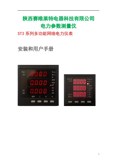
ST3 系列多功能网络电力仪表
安装和用户手册
1
警告
1、本设备只能由专业人员进行操作。 2、不认真按照手册上的说明操作而引起的故障,本公司将不承担任何责任。 3、本设备所有的保护功能仅限用于报警或辅助保护。
危险
1、本设备只能由专业人员进行安装和维护。 2、对本设备进行任何操作前,应隔离电压输入和电源供应,并且短路所有电流 互感器的二次绕组。 3、在将本设备通电前,确认设备完整并所用的端子都已连接好。 4、供设备的电源电压范围在设备额定电压范围之内。
4
1.2
参数
技术参数
指标 0.2 级 0.5 级 2级 400V 以下(三相 Y 型) 400V 以上(三相 Y 型和三相△形) 额定电流输入 1A 或 5A,持续 1.2 倍,瞬间电流 10 倍/1 秒 额定电压输入 100V 或 220V,持续 1.2 倍,电压 2 倍/1 秒 1 个固态继电器, 每度电 500 个脉冲数, 单个脉冲宽度 80ms 1 个固态继电器, 每度电 500 个脉冲数, 单个脉冲宽度 80ms 交流 220V ± 25% 4~20mA 直流信号,最大 400 欧姆负载 交流 220V/5A,直流 30V/5A 交流 85V ~ 265V;直流 80V ~ 300V ≈3W 2KV(测试电压为交流有效值) ≥ 50MΩ IEC 61000-4-2,Level 3 IEC 61000-4-3,Level 3 IEC 61000-4-4,Level 3 IEC 61000-4-5,Level 3 EN 55022,Class B EN 55022,Class B -20℃~+70℃ -30℃~+80℃ 相对湿度:5%~95%,无凝露
Upland AccuRoute Ricoh ESA v3.0 快速入门指南说明书
Upland AccuRoute 6 Riverside Drive Andover, MA 01810Phone: (978) 327‐5700Toll ‐free US: 1‐800 886‐7845Upland Software Headquarters Frost Bank Tower401 Congress Avenue, Suite 1850Austin, TX 78701‐3788Toll Free: (855) 944‐7526Embedded AccuRoute ®for Ricoh ESA v3.0Quick Start GuideEmbedded AccuRoute® Ricoh ESA v3.0 Quick Start Guide © 2017 by Omtool, Ltd. (Upland AccuRoute) All rights reserved. Omtool, AccuRoute, Genifax, Image‐In, ObjectArchive, ScanFacts,and the Company logo are trademarks of the Company. Trade names and trademarks of other companies appearing in thisdocument are the property of their respective owners.Omtool product documentation is provided as part of the licensed product. As such, the documentation is subject to the terms outlined in the End User License Agreement. (You are presented with the End User License Agreement during the product installation. By installing the product, you consent to the terms therein.)Permission to use the documentation is granted, provided that this copyright notice appears in all copies, use of the documentation is for informational and non‐commercial or personal use only and will not be copied or posted on any network computer or broadcast in any media, and no modifications to the documentation are made. Accredited educational institutions may download and reproduce the documentation for distribution in the classroom. Distribution outside the classroom requires express written permission. Use for any other purpose is expressly prohibited by law.Omtool and/or its suppliers make no guaranties, express or implied, about the information contained in the documentation. Documents and graphics contained therein could include typographical errors and technical inaccuracies. Omtool may make improvements or changes to the documentation and its associated product at any time.Upland AccuRoute ResourcesThe Upland CommunityThe Upland Community is the central hub for Upland customer information, in the community you can: ·Track tickets·Search and Download Knowledge·Interact in Upland Forums·Stay up to date on AccuRoute and/or Upland NewsAccess the Community by logging in with your company email at:https:///hc/en‐usCustomer Service and Technical Support Contact Information·Phone: (978) 327 6800 or (1‐888) 303 8098·E‐mail: omtool‐**************************·Community: https:///hc/en‐usNOTE: Technical support requires an active support contract. For more information go to:https:///accuroute/customer‐success/support‐overview/Sales, Consulting Services, Licenses and Training·Phone: (978) 327 5700 or (1‐800) 886 7845·Email:******************************Using the Routing Sheet OptionA Routing Sheet is a special page with Embedded Directive data containing distribution instructions for your document. With the Routing Sheet option, the device delivers the scanned document and Routing Sheet to the AccuRoute server, which decodes the Embedded Directive data and distributes the document to intended recipients.1Generate and print a Routing Sheet using AccuRoute Desktop or the AccuRoute Web Client.2Assemble your document with the Routing Sheet at the front or back. Then go to the device.3At the device, load the document into the feeder or place it on the exposure glass. (Use the exposure glassonly if scanning a single page.)4Press Routing Sheet. The device shows the ready to scan page.Some devices allow access to the buttons afterselecting the Apps icon or a top level button.Note: The device button icons may vary, but thesteps remain consistent. 5Press Start on the hard keypad.The device scans the document.6If job build mode is on (ScanSourceMode is set to SADF in the configuration file or in the Settingsscreen), you will see a document distribution messagewith two options:•To scan another document using the Routing Sheet option, press Start to repeat the process.•If scanning is complete, press #. The device initiates a routing request and a summary message appears on thescreen.7Press OKto return to the main AccuRoute page.Using the Device Information OptionThe Device Information option provides a screen of detailed information about the multi-function printer (MFP).1Go to the device.2Press Device Information. (If this option is notvisible, find it using the scroll bar.)Some devices allow access to the buttons afterselecting the Apps icon or a top level button.3The following types of information appear on thedisplay:- Device name and model- Device IP address- Device serial number- Device location, if available4Optionally, press Print to print the screen informationon the device.5Press OK to return to the main AccuRoute page.Using the Fax Release OptionUsing the Fax Release option, the device delivers the document to the AccuRoute server, which can hold or print your faxes as necessary.Step 1: Log in to the HP MFP device with your PIN1Assemble your document and go to the device.2Press Fax Release. (If you do not see this option, find it using the scroll bar.)Some devices allow access to the buttons afterselecting the Apps icon or a top level button.3Select the Fax Number to which your fax messages are sent.4In the Enter PIN page that opens, enter the PIN number assigned to you by the Administrator.5Select Next. Two options appear: Enable Manual Hold and Print Pending Jobs.-To Print Pending Jobs, continue to Step 2.-To Enable or Disable Manual Hold, continue toStep 3.Step 2: Print Pending JobsTo print faxes:Select the Print Pending Jobs option.The device prints all faxes that were in the queue holdfor the selected fax number, including those that werereceived after the normal office business hours.Step 3: Enable or Disable Manual HoldTo enable Manual Hold:Select the Enable Manual Hold option to override the current print schedule assigned to the fax number. Use this option if you do not want to print faxes at this time. For example, you can enable Manual Hold when going to a meeting.To disable Manual Hold:Once you enable Manual Hold, the Release Manual Hold option appears on the Fax Release screen.•To disable Manual Hold, select the Release Manual Hold option. The device releases and prints all faxesthat were held since Manual Hold was set.Using the Job Queue OptionYou can use the Job Queue option to obtain a list of jobs recently submitted to the AccuRoute server from a specific multi-function printer (MFP). This is useful, for example, to check the status of jobs for which no notification occurs when complete. Job Queue functionality depends on whether or not you are logged in as an authenticated user.For all users, Job Queue can provide a list of all items previously scanned on an MFP, based on the serial number and IP address of that device. The system administrator configures the type of items or jobs that can be reported.For authenticated users, Job Queue can list any previously scanned items associated with the logged-in user.1Go to the device.2Press Job Queue. (If this option is not visible, find itusing the scroll bar.)Some devices allow access to the buttons afterselecting the Apps icon or a top level button.3The following Job Queue properties appear on thedisplay:- All faxes sent from this device- All scanned jobs from this device4Authenticated users will see the following Job Queueproperty on the display:- All my faxes5Press OK to return to the main AccuRoute page.Using the Mobile Reservation OptionUse the Mobile Reservation option to distribute a a scanned document using a previously generated Mobile Scan Reservation Code. Mobile Scan Reservation Codes are created on the Mobile Client.The device uses the Mobile Scan Reservation Code to appropriately route your scanned document to the AccuRoute server, which decodes the reservation and distributes the document to intended recipients.1Assemble your document and go to the device.2Press Mobile Reservation. (If this option is not visible, find it using the scroll bar.)Some devices allow access to the buttons afterselecting the Apps icon or a top level button.3You are prompted for your Mobile ScanReservation Code. Enter the code generated by yourMobile Client.4Load the document into the document feeder or place it on the exposure glass. (Use the exposure glass only ifscanning a single page.)5Optionally, press More Options to change scan settings (such as parameters for control overdocument routing and formatting).6Press Start to begin scanning. A progress indicator will display.7Wait for the job to finish. (Alternatively, press Cancel Job to stop the scan job.)When transfer is complete, a message indicates the jobstatus.8To scan another document to the specified network folder, press Back.9Press OKto return to the main AccuRoute page.Using the Fax OptionWhen you enter a fax number and scan your document using the Fax option, the device delivers the document to the AccuRoute server, which sends the fax to intended recipients.1Assemble your document and go to the device.2Load the document into the document feeder or place it on the exposure glass. (Use the exposure glass only ifscanning a single page.)3Press Fax. The device prompts you to enter details about the fax.Some devices allow access to the buttons afterselecting the Apps icon or a top level button.Note: The device button icons may vary, but thesteps remain consistent.4Enter information about the fax:a To enter the fax number, press the Keyboard buttonbeside the Fax Number text box and enter thenumber on the keyboard that appears.b To add a cover page, press Yes.c To enter the sender name, press the Keyboardbutton beside the Sender Name text box and enterthe sender name on the keyboard that appears.d To enter the recipient name, press the Keyboardbutton beside the Recipient Name text box andenter the recipient name on the keyboard that appears.e To enter the subject, press the Keyboard buttonbeside the Subject text box and enter an appropriatesubject on the keyboard that appears.5Press Next. The device shows a summary of this document distribution option.6Press Start on the hard keyboard. The device scans the document.7If job build mode is on (ScanSourceMode is set to SADF in the configuration file or in the Settingsscreen), you will see a document distribution messagewith two options:•To scan additional pages, press Start to repeat the process.•If scanning is complete, press #. The device initiates a routing request and a summary message appears on thescreen.8Press OKto return to the main AccuRoute page.Using the Personal Distributions OptionThe Embedded Directives that you can create on the AccuRoute Desktop are document distribution options called Personal Distributions. Personal Distributions are created for use by an individual. For example, you may have a distribution defined for sending information to people within your company and another distribution for sending information outside the company.Before using this option, you must create a Personal Distribution using either the AccuRoute Desktop or the AccuRoute Web Client. Ask your system administrator for assistance.With the Personal Distributions option,the device delivers the scanned document to the AccuRoute server, which sends the document to the intended recipients.1Assemble your document and go to the device.2Load the document into the document feeder or place it on the exposure glass. (Use the exposure glass only ifscanning a single page.)3Press Personal Distributions. The device prompts you to log in.Some devices allow access to the buttons afterselecting the Apps icon or a top level button.Note: The device button icons may vary, but thesteps remain consistent.4Enter your login credentials:-Press the Keyboard button beside the Email text boxand enter your email ID on the keyboard that appears.-Verify that the domain name is correct. If not, press theKeyboard button beside the Domain text box andmodify the domain name.5Press OK. A list of your Personal Distribution options appears.6Select a Personal Distribution. The device shows a summary of this document distribution option.7Press Start on the hard keypad. The device scans the document.8If job build mode is on (ScanSourceMode is set to SADF in the configuration file or in the Settingsscreen), you will see a document distribution messagewith two options:•To scan additional pages, press Start to repeat the process.•If scanning is complete, press #. The device initiates a routing request and a summary message appears on thescreen.9Press OKto return to the main AccuRoute page.Using the Public Distributions OptionA system administrator creates Public Distributions for use by a group. For example, all members of the marketing group may have a distribution predefined specifically for their use.Using the Public Distributions option, the device delivers the scanned document to the AccuRoute server, which decodes the distribution and sends the document to the intended recipients.1Assemble your document and go to the device.2Load the document into the document feeder or place it on the exposure glass. (Use the exposure glass only ifscanning a single page.)3Press Public Distributions.Some devices allow access to the buttons afterselecting the Apps icon or a top level button.Note: The device button icons may vary, but thesteps remain consistent. The example image is from anHP FutureSmart device.4 A list of the Public Distribution options appears.Select a distribution from the list. The device shows asummary of this document distribution.5Press Start on the hard keypad. The device scans the document.6If job build mode is on (ScanSourceMode is set to SADF in the configuration file or in the Settingsscreen), you will see a document distribution messagewith two options:•To scan additional pages, load the pages and press Start to repeat the process.•If scanning is complete, press #. The device initiates a routing request and a summary message appears on thescreen.7Press OKto return to the main AccuRoute page.Using the Scan to Folder OptionUsing the Scan to Folder option, the AccuRoute server sends the scanned document to a folder predetermined by your system administrator.1Assemble your document and go to the device.2Press Scan to Folder and the ready to scan page appears.3Load the document into the document feeder or place it on the exposure glass. (Use the exposure glass only ifscanning a single page.)4Press Start on the hard keypad.The device scans the document.5If the job build mode is on (ScanSourceMode is set to SADF in the configuration file or in the Settingsscreen), the following message appears.Depending on your device configuration, thescreens that appear when your scan is complete maydiffer.6To scan additional pages, repeat the process.7When scanning is complete, press # on the hard keypad.The device initiates a routing request and the followingmessage appears.8To end the session and return to the main AccuRoute menu, press the OKbutton.Using the Scan to Me OptionWith the Scan to Me option, the AccuRoute server sends the scanned document to your PC for further review and routing. Based on a personal directive (a rule defined by a system administrator), AccuRoute sends the document to your e-mail address (the default), a Windows home folder or other intended recipients.Before you can use the Scan to Me option, you must create your personal directive on the AccuRoute Desktop Client. Consult your network or system administrator for directions on how to set up your directive.Note that without a Scan To Me directive set up, a scanned document is sent to your email address by default.1Assemble your document and go to the device.2Load the document into the document feeder or place it on the exposure glass. (Use the exposure glass only ifscanning a single page.)3Press Scan to Me and the device prompts you to log in.Some devices allow access to the buttons afterselecting the Apps icon or a top level button.Note: The device button icons may vary, but thesteps remain consistent.4Enter your login credentials:Depending on your authentication setup, the loginscreen and the data you are required to enter mayvary.-Press the Keyboard button beside the Email text boxand enter your email ID on the keyboard that appears.-Verify that the domain name is correct. If not, press theKeyboard button beside the Domain text box andmodify the domain name.5Press OK. The device shows a summary page.6Press Start on the hard keypad. The device scans the document.7If job build mode is on (ScanSourceMode is set to SADF in the configuration file or in the Settingsscreen), you will see a document distribution messagewith two options:•To scan additional pages, press Start to repeat the process.•If scanning is complete, press #. The device initiates a routing request and a summary message appears on thescreen.8Press OKto return to the main AccuRoute page.Using the Scan to My Files OptionUsing the Scan to My Files option, the device delivers the scanned document to the AccuRoute server, which sends it as an electronic file to the “My Files” folder on the AccuRoute Desktop Client or AccuRoute Web Client.1Assemble your document and go to the device.2Load the document into the document feeder or place it on the exposure glass. (Use the exposure glass only ifscanning a single page.)3Press Scan to My Files and the device prompts you to log in.Some devices allow access to the buttons afterselecting the Apps icon or a top level button.Note: The device button icons may vary, but thesteps remain consistent.4Enter your login credentials:Depending on your authentication setup, the loginscreen and the data you are required to enter mayvary.-Press the Keyboard button beside the Email text boxand enter your email ID on the keyboard that appears.-Verify that the domain name is correct. If not, press theKeyboard button beside the Domain text box andmodify the domain name.5Press OK. The device shows a summary page.6Press Start on the hard keypad. The device scans the document.7If job build mode is on (ScanSourceMode is set to SADF in the configuration file or in the Settingsscreen), you will see a document distribution messagewith two options:•To scan additional pages, press Start to repeat the process.•If scanning is complete, press #. The device initiates a routing request and a summary message appears on thescreen.8Press OKto return to the main AccuRoute page.。
Visual Components 体验指南说明书
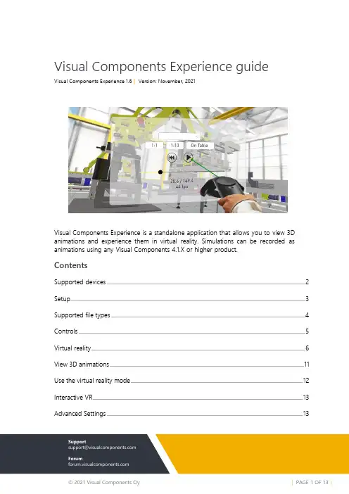
Visual Components Experience guideVisual Components Experience 1.6 | Version: November, 2021Visual Components Experience is a standalone application that allows you to view 3D animations and experience them in virtual reality. Simulations can be recorded as animations using any Visual Components 4.1.X or higher product.ContentsSupported devices (2)Setup (3)Supported file types (4)Controls (5)Virtual reality (6)View 3D animations (11)Use the virtual reality mode (12)Interactive VR (13)Advanced Settings (13)Support****************************ForumSupported devicesWindows OS▪Any device running Windows 8.1 or 10 can be used for viewing 3D animations▪Refer to the minimum requirements for a Visual Components 4.x producthttps:///system-requirements▪An alternative for viewing 3D animations is the mobile version of Visual Components Experience.Compatible VR DevicesVisual Components Experience relies on SteamVR for virtual reality functionality. Any Head-mounted Display (HMD) that is supported by SteamVR should also support VC Experience. However, this is not guaranteed, and using one of the tested and verified devices listed below is recommended.Tested VR DevicesNote that if your computer has a Mini DisplayPort, you need to use a Mini DisplayPort cable. Based on field tests and feedback, adapters may not work.•HTC Vive and Vive Pro•Oculus Rift S•Samsung HMD Odysseyo To use the Samsung HMD Odyssey with VC Experience, you need to also install Windows Mixed Reality for SteamVR from the Steam store.o When you want to use the device with VC Experience, launch theWindows Mixed Reality for SteamVR first. Then, launch VisualComponents Experience in VR mode.•Valve IndexSetupFor viewing 3D animations, install Visual Components Experience on your device here: https:///products/downloadsFor virtual reality, this guide assumes that you are using HTC Vive. For all other devices, refer to the manufacturer on how to install new apps, set up the device, and interact with VR objects.1.Set up your device according to the manufacturer’s instructions.2.Install Steam onto the device.For more information, see /about.3.Install SteamVR as follows:a.Run Steam.b.In Steam, go to Library > Tools and then search for SteamVR.c.Right-click SteamVR and click Install Game.Supported file typesVisual Components Experience allows you to open and play VCAX files. A VCAX file is a container for a 3D simulation recorded as an animation using a Visual Components 4.x product.To create a VCAX file, see the Record a Simulation as Animation tutorial:•To watch the tutorial from Visual Components Academy, go tohttps:///lessons/record-a-simulation-as-animation/•To download the tutorial as video, go to http://bit.ly/2AezlWCYou can double-click a VCAX file on your device to automatically open it in Visual Components Experience.Otherwise, you need to add VCAX files to the following folder to list them in the app: C:\Users\%username%\Documents\Visual Components\ExperienceThe Experience 1.6 introduces also a VCAX point cloud support.Controls 3D Viewing1.Select animation allows you toselect and open a VCAX file inthe M y Animations folder of yourVisual Components documents.2.Viewport displays the 3D sceneand animation.3.About displays app information.4.Quality Settings displays a dialogfor c ontrolling the level of detail(LOD) and quality level of theviewport. The frame rate (FPS) ofthe scene is also indicated basedon the current settings.5.Slider and Thumbshow the position ofanimation and allowyou to jump forwardor backward in time. 6.Reset returns animation to its initial stateand time of zero.7.Play allows you to start or stopanimation.8.Time shows the position (in seconds) ofanimation followed by its duration.9.Playback speed can be changed to playthe animation slower or faster.Virtual realityMain Menu1.Select animation allows you to select and open a VCAX file in the My Animationsfolder of your Visual Components documents.2.1:1 scales components to their original size.3.Reset returns animation to its initial state and time of zero.4.Slider and Thumb show the position of animation and allow you to jump forward orbackward in time.5.Time shows the position (in seconds) of animation followed by its duration.6.Ray is the pointer of a connected joystick that can be used for selecting objects andmenu items.7.1:10 scales components to 1/10th of their original size.8.On Table scales components to HTC Vive play area.9.Play allows you to start or stop animation.10.Quality Settings displays a dialog for controlling the level of detail (LOD) and qualitylevel of the viewport. The frame rate (FPS) of the scene is also indicated based on the current settings.11.About displays app information.12.Playback speed can be changed to play the animation slower or faster.HeadsetA headset allows you to look around in the scene. You must connect the headset to SteamVR b efore using Visual Components Experience in Virtual Reality mode.Default bindings of controlsThe following tables show what happens by default when you use the controllers in VC Experience.Some actions can send data from Visual Components Experience to the Visual Components Premium application, provided that you have the layout open in Visual Components. Note that sending data also requires setting up a Python script with vcVREvent statements.Custom bindings of controlsIf you are not enjoying the default bindings, now you have the possibility to modify the controller bindings in SteamVR.View 3D animations1.Run Visual Components Experience.2.Click 3D.3.Click Select animation and select an animation to load it in the scene.4.Do any of the following as needed:▪To remove the animation, in Select animation, click <Clear>.▪To return to the default view, in Select animation, click <Reset View>.▪To orbit the camera in the scene, press and hold the right mouse button.▪To pan the camera in the scene, press and hold the left and right mouse buttons. ▪To zoom the camera in the scene, rotate the mouse wheel.Use the virtual reality mode1.Run SteamVR, and then connect your headset and joystick(s).2.Run Visual Components Experience.3.Click VR.4.With the joystick, press the Menu button, cast a ray, and use Select animationto load an animation in the scene.5.Do any of the following as needed:▪To scale components, use the main menu. Generally, you would use 1:10 to view a large scene or On Table to walk around and view a scene.▪To remove the animation, in Select animation, click <Clear>.▪To return to the default view, in Select animation, click <Reset View>.Interactive VRInteractive VR requires Visual Components Premium 4.2 or higher product. Animationstreaming is required to interact with components in VR. See the Academy lessonStreaming Simulation to VR on how to enable animation streaming.For details on using interactive VR, check out the Academy tutorials. Components thatenable interactive VR are found in eCatalog directory VR Interaction.Advanced users should see the Python API documentation for vcVREvents.Advanced SettingsOn the launcher, you have the option to specify Advanced Settings related to animationstreaming and Anti-Aliasing.Streaming Host is the IP address of the computer where the VC Premium application isrunning. If VC Premium and VC Experience are running on the same machine, then IP-address127.0.0.1. Streaming Port must match the port defined in VC Premium.Anti-aliasing settings can be changed by modifying the Antialiasing mode andAntialiasing FXAA (Fast Approximate Anti-Aliasing) options.| PAGE 13 OF 13 |ADVANCED SETTINGS。
Eaton 中高压封闭型开关产品选择指南说明书
Volume 3—Power Distribution and Control Assemblies CA08100004E—March V3-T6-16Medium Voltage Metal-Enclosed SwitchesOutdoor Medium Voltage Switch6.1IntroductionProduct Selection Guide . . . . . . . . . . . . . . . . . . . . . . . . . . . . . . . . . . .V3-T6-26.2Medium Voltage Switch—MVSProduct Description . . . . . . . . . . . . . . . . . . . . . . . . . . . . . . . . . . . . . . V3-T6-3Application Description . . . . . . . . . . . . . . . . . . . . . . . . . . . . . . . . . . . . V3-T6-3Features, Benefits and Functions . . . . . . . . . . . . . . . . . . . . . . . . . . . . V3-T6-4Standards and Certifications . . . . . . . . . . . . . . . . . . . . . . . . . . . . . . . . V3-T6-4Reference Information . . . . . . . . . . . . . . . . . . . . . . . . . . . . . . . . . . . . V3-T6-4Product Selection . . . . . . . . . . . . . . . . . . . . . . . . . . . . . . . . . . . . . . . . V3-T6-4Technical Data and Specifications . . . . . . . . . . . . . . . . . . . . . . . . . . . .V3-T6-46.3Medium Voltage Switch and Breaker—MSBProduct Description . . . . . . . . . . . . . . . . . . . . . . . . . . . . . . . . . . . . . . V3-T6-5Application Description . . . . . . . . . . . . . . . . . . . . . . . . . . . . . . . . . . . . V3-T6-5Features, Benefits and Functions . . . . . . . . . . . . . . . . . . . . . . . . . . . . V3-T6-5Standards and Certifications . . . . . . . . . . . . . . . . . . . . . . . . . . . . . . . . V3-T6-6Reference Information . . . . . . . . . . . . . . . . . . . . . . . . . . . . . . . . . . . . V3-T6-6Product Selection . . . . . . . . . . . . . . . . . . . . . . . . . . . . . . . . . . . . . . . . V3-T6-6Technical Data and Specifications . . . . . . . . . . . . . . . . . . . . . . . . . . . .V3-T6-66.4Metal-Enclosed Breaker—MEBProduct Description . . . . . . . . . . . . . . . . . . . . . . . . . . . . . . . . . . . . . . V3-T6-7Application Description . . . . . . . . . . . . . . . . . . . . . . . . . . . . . . . . . . . . V3-T6-7Features, Benefits and Functions . . . . . . . . . . . . . . . . . . . . . . . . . . . . V3-T6-7Standards and Certifications . . . . . . . . . . . . . . . . . . . . . . . . . . . . . . . . V3-T6-8Reference Information . . . . . . . . . . . . . . . . . . . . . . . . . . . . . . . . . . . . V3-T6-8Product Selection . . . . . . . . . . . . . . . . . . . . . . . . . . . . . . . . . . . . . . . . V3-T6-8Technical Data and Specifications . . . . . . . . . . . . . . . . . . . . . . . . . . . .V3-T6-86.5Unitized Power Centers—UPCProduct Description . . . . . . . . . . . . . . . . . . . . . . . . . . . . . . . . . . . . . . V3-T6-9Features, Benefits and Functions . . . . . . . . . . . . . . . . . . . . . . . . . . . . V3-T6-9Standards and Certifications . . . . . . . . . . . . . . . . . . . . . . . . . . . . . . . . V3-T6-9Reference Information . . . . . . . . . . . . . . . . . . . . . . . . . . . . . . . . . . . . V3-T6-9Product Selection . . . . . . . . . . . . . . . . . . . . . . . . . . . . . . . . . . . . . . . . V3-T6-9Technical Data and Specifications . . . . . . . . . . . . . . . . . . . . . . . . . . . .V3-T6-106.6OEM Medium Voltage Switch Components—MVS-CProduct Description . . . . . . . . . . . . . . . . . . . . . . . . . . . . . . . . . . . . . . V3-T6-11Application Description . . . . . . . . . . . . . . . . . . . . . . . . . . . . . . . . . . . . V3-T6-11Features, Benefits and Functions . . . . . . . . . . . . . . . . . . . . . . . . . . . . V3-T6-11Standards and Certifications . . . . . . . . . . . . . . . . . . . . . . . . . . . . . . . . V3-T6-12Reference Information . . . . . . . . . . . . . . . . . . . . . . . . . . . . . . . . . . . . V3-T6-12Product Selection . . . . . . . . . . . . . . . . . . . . . . . . . . . . . . . . . . . . . . . . V3-T6-12Technical Data and Specifications . . . . . . . . . . . . . . . . . . . . . . . . . . . .V3-T6-1266.1Medium Voltage Metal-Enclosed SwitchesIntroductionOutdoor Medium Voltage SwitchContentsDescriptionIntroductionAn EatonGreen SolutionIntroductionProduct Selection GuideProduct Offering Chart—Metal-Enclosed 1Notes1Additional products not shown include medium voltage transfer, high resistance ground and low profile switchgear.2Listings are voltage dependant. See individual product sheets for detail.Description MVS MEB MSB UPC Mini-MVSVoltage5, 15, 27, 38 kV5, 15 kV5, 15 kV5, 15 kV 5 kV onlyOperation duty cycle Low High High Low LowEnclosure Indoor, outdoor aisleless Indoor, outdoor aisleless Indoor, outdoor aisleless Indoor only Indoor, outdoor aisleless Listed UL®, CSA®———UL, CSAAssembly standards ANSI/IEEE®, C37.30.3, C37.20.4,C37.22, C37.57, C37.58,CSA 22.2 #31 2ANSI/IEEE, C37.30.3, C37.20.4,C37.22, C37.57, C37.58,CSA 22.2 #31ANSI/IEEE, C37.30.3, C37.20.4,C37.22, C37.57, C37.58,CSA 22.2 #31—ANSI/IEEE, C37.30.3, C37.20.4,C37.22, C37.57, C37.58,CSA 22.2 #31 2Circuit breaker type N/A VCP-W VCP-TR (5, 15 kV), VCP-W 27 kV N/A N/ACircuit breaker mounted N/A Drawout Fixed N/A N/ASeismically rated Zone 4 toCalifornia Building Code Title 24Yes Yes Yes Yes YesBIL ratings60 kV (5 kV)60 kV (5 kV)60 kV (5 kV)60 kV (5 kV)60 kV (5 kV)95 kV (15 kV)95 kV (15 kV)95 kV (15 kV)95 kV (15 kV)125 kV (27 kV)125 kV (27 kV)150 kV (38 kV)Main bus ratings800, 1200A (5/15/27/38 kV)800, 1200A (5/15 kV)800, 1200A (5/15/27 kV)N/A N/A, cable in, cable out application Breaker ratings N/A1200A (5/15 kV)600, 800, 1200A (5/15/27 kV)N/A N/AOvercurrent protective device Yes (fused)Yes Yes Yes (fused)Yes (fused)Short-circuitinterrupting capacityPer fuse IC29, 41, 63 kA (5 kV)16, 20, 25, 40 kA (5/15 kV)Per fuse IC Per fuse IC18, 28, 37, 63 kA (15 kV)25 kA (27 kV)Conduit entry Top or bottom Top or bottom Top or bottom Top or bottom Top or bottomV3-T6-2Volume 3—Power Distribution and Control Assemblies CA08100004E—March Volume 3—Power Distribution and Control Assemblies CA08100004E—March V3-T6-366.2Medium Voltage Metal-Enclosed SwitchesMedium Voltage Switch—MVSIndoor Medium Voltage Switch—MVS Bus Connection toDry-Type TransformerContentsDescriptionPage Medium Voltage Switch—MVSProduct Description . . . . . . . . . . . . . . . . . . . . . V3-T6-3Features, Benefits and Functions. . . . . . . . . . . V3-T6-4Standards and Certifications . . . . . . . . . . . . . . V3-T6-4Reference Information . . . . . . . . . . . . . . . . . . V3-T6-4Product Selection . . . . . . . . . . . . . . . . . . . . . . V3-T6-4Technical Data and Specifications . . . . . . . . . .V3-T6-4An EatonGreen SolutionProduct DescriptionEaton’s MVS load interrupter switchgear is a metal-enclosed assembly consisting of a switch, bus and fuses.MVS switchgear is available in one or more vertical section assemblies. The three-pole switch willinterrupt its rated load current with its quick-make, quick-break mechanism. Optional fuses ensure short-circuit protection at all times.MVS Arc-ResistantEaton’s 5/15 kV MVS metal-enclosed load interrupter switchgear is now available with arc-resistant construction withaccessibility Type 2B in accordance with IEEEC37.20.7. MVS arc-resistant switchgear is designed for indoor use. It can also be used outdoor with space heaters. It can be configured for a variety of applications. Switches can be supplied with manual or electrical operating mechanisms and with or without primaryfuses. Per IEEE C37.20.7, the Type 2B accessibility rating provides arc-resistantfeatures and protection at the freely accessible exterior (front, back and sides) of the equipment as well as in front of the instrument/control compartment with the instrument/controlcompartment door opened while the equipment is energized and operating normally.Application DescriptionMVS switchgear provides safe, reliable switching and fault protection for medium voltage circuits where high duty cycle operation is not needed.●Single switch and transformer primary ●Duplex switch ●Selector switch●Automatic transfer control66.2Medium Voltage Metal-Enclosed SwitchesMedium Voltage Switch—MVSFeatures, Benefits and FunctionsQuick-make, quick-breakmechanism: A reliable heavy-duty coil spring mechanismdrives the switch blades athigh speed into either theopen or the closed position.The speed of operation isindependent of the personoperating the switch.Direct drive mechanism:A metal-to-metal direct drivemechanism eliminates chainsor cables that may break orneed adjusting.DE-ION® arc interruption:DE-ION arc chambers andspring-loaded auxiliary bladesensure fast load currentinterruption and eliminatearcing damage to themain contacts.Positive switch positionindication: Red and greenmultilingual (English/Spanish/French) labels located directlyon the switch operatingmechanism give visualindication of switch position.Interlocked for safety:Mechanical interlocks preventclosing the switch when thecompartment door is open, orthe opening of the door whenthe switch is closed.Safety under faultconditions: The switch,depending upon the ratedvoltage, is available withthree or four fault-closingoperations with ratingsup to 61,000 amperes rmsasymmetrical, exceedingthe industry standards onetime operation.Safety barrier: A hingedsolid metal barrier with aperforated metal viewing areashields the disconnect switchwhen the compartment dooris opened.Short-circuit protection:A full range of Eaton fusingoptions is available for short-circuit protection.Eaton's SF6-freeswitchgear: Eaton mediumvoltage switchgear usevacuum switches combinedwith solid insulation material.This environmentally-friendlytechnology avoids the use ofSF6 as an insulation gas.Indoor Medium Voltage Switch—MVS Bus Connection toDry-T ype T ransformerInspectionWindowSwitch DriveMechanismOperatingHandle(Mounted inAccess Door)DE-ION ArcInterruptersLocated BehindSwitch BarrierInterlockFusesHigh DielectricInsulation UsedBetween SwitchPhases andGround on15 kV OnlyHinged InternalSwitch BarrierStandards andCertificationsMVS switchgear meets orexceeds IEEE® C37.20.3 as itapplies to metal-enclosedswitchgear.Either UnderwritersLaboratories® (UL) orCanadian StandardsAssociation® (CSA) listing isavailable for MVS switchgear inmany configurations, with anumber of options.MVS switchgear is availableseismically qualified to meetthe requirements of theUniform Building Code®(UBC), California Title 24 andBOCA® requirements in manyconfigurations with a numberof options.Reference InformationSee Consulting ApplicationGuide for detailed list of ratingsand options. For renewal parts,see CA08105001E.Product SelectionContact Eaton for pricing.Technical Dataand Specifications●Rated maximum voltageclasses of 5, 15, 27 and38 kV●Rated impulse levels, kVBIL: 60, 95, 125, 150●Continuous and load-breakratings: 600 amperesavailable at all voltageclasses; 1200 amperesavailable at 5 and 15 kV●Designs available in indoorand outdoor non-walk-inconfigurations●Manual or motor operatedV3-T6-4Volume 3—Power Distribution and Control Assemblies CA08100004E—March Volume 3—Power Distribution and Control Assemblies CA08100004E—March V3-T6-566.3Medium Voltage Metal-Enclosed SwitchesMedium Voltage Switch and Breaker—MSBIndoor Medium Voltage Switch and Fixed Breaker—MSBContentsDescriptionPage Medium Voltage Switch and Breaker—MSBStandards and Certifications . . . . . . . . . . . . . . V3-T6-6Reference Information . . . . . . . . . . . . . . . . . . . V3-T6-6Product Selection . . . . . . . . . . . . . . . . . . . . . . V3-T6-6Technical Data and Specifications . . . . . . . . . .V3-T6-6An EatonGreen SolutionProduct DescriptionEaton’s MSB switchgear is an integrated assembly of a visible load-break disconnect switch, fixed-mounted vacuum circuit breaker, and control devices that are integrated electrically and mechanically for circuit protection. All major components are manufactured by Eaton, establishing one source of responsibility for the equipment and ensuring high standards in quality, coordination, reliability and service. MSB switchgear would typically be used where both cost and protection are important design parameters.Application DescriptionApplications include ground fault protection, primary and/or secondary switching, and protection on unit substations, automatic transfer switching at medium voltage levels, capacitor switching, high duty cycle and tight system coordination protection.MSB switchgear can also be an economic benefit in single-ended substations because it may allow the customer to eliminate the secondary main protection and switching device.●Low resistance ground schemes●Single-ended substation designs●Overcurrent protectionFeatures, Benefits and Functions●Visible isolation●Fully rated fixed vacuum circuit breaker●Electrical operation ●No fuses●Improved coordination capability●Improved transformer protection●Ground fault protection ●Capacitor switching●High switching duty cycle ●Integral overcurrent protectionEaton's SF 6-freeswitchgear: Eaton medium voltage switchgear usevacuum switches combined with solid insulation material. This environmentally-friendly technology avoids the use of SF 6 as an insulation gas.66.3Medium Voltage Metal-Enclosed SwitchesMedium Voltage Switch and Breaker—MSBStandards andCertificationsMSB switchgear meets orexceeds IEEE C37.20.3 as itapplies to metal-enclosedswitchgear.CSA listing is available forMSB switchgear in manyconfigurations with a numberof options.MSB switchgear is availableseismically qualified to meetthe requirements of theUniform Building Code,California Title 24 andBOCA requirements inmany configurations witha number of options.Reference InformationSee Consulting ApplicationGuide for detailed list of ratingsand options. For renewal parts,see CA08105001E.Product SelectionContact Eaton for pricing.Technical Dataand Specifications●Rated maximum voltagesof 4.76–15 kV●Continuous current ratingsup to 1200 amperes●25 and 40 kA rmssymmetrical short-circuitinterrupting capacity●Designs available in indoorand outdoor non-walk-inconfigurations●Single vertical section andtransformer primaryconfigurations●Lineups consisting of MSBand MVS vertical sectionsV3-T6-6Volume 3—Power Distribution and Control Assemblies CA08100004E—March Volume 3—Power Distribution and Control Assemblies CA08100004E—March V3-T6-766.4Medium Voltage Metal-Enclosed SwitchesMetal-Enclosed Breaker—MEBIndoor Metal-Enclosed Drawout Vacuum Breaker—MEBUsed as Main for Two Fused SwitchesContentsDescriptionPage Metal-Enclosed Breaker—MEBStandards and Certifications . . . . . . . . . . . . . . V3-T6-8Reference Information . . . . . . . . . . . . . . . . . . . V3-T6-8Product Selection . . . . . . . . . . . . . . . . . . . . . . V3-T6-8Technical Data and Specifications . . . . . . . . . .V3-T6-8Product DescriptionEaton’s MEB switchgear is a metal-enclosed assembly of single high drawout VCP-W vacuum circuit breakers and control devices that are integrated electrically for circuit protection. (For drawout vacuum breaker metal-clad switchgear, type VacClad-W, see Volume 3, T ab 7) All major components are manufactured by Eaton, establishing one source of responsibility for the equipment and ensuring high standards in quality, coordination, reliability and service.Application DescriptionMEB can be applied as the primary main device and integrated with fused feeder switches in a lineup of fused MVS switchgear.Applications include ground fault protection, primary and/or secondary switching, and protection on unit substations, automatictransfer switching at medium voltage levels, capacitor switching, high duty cycle and tight system coordination protection. MEB switchgear can also be an economic benefit in single-ended substations because it may allow the customer to eliminate the secondary main protection and switching device.●Low resistance ground schemes●Single-ended substation designs●Overcurrent protectionFeatures, Benefits and Functions●Fully rated drawout vacuum circuit breaker ●Electrical operation ●Improved coordination capability●Improved transformer protection●Ground fault protection ●Capacitor switching●High switching duty cycle ●Integral overcurrent protection66.4Medium Voltage Metal-Enclosed SwitchesMetal-Enclosed Breaker—MEBStandards andCertificationsMEB switchgear meets orexceeds IEEE C37.20.3 as itapplies to metal-enclosedswitchgear.CSA listing is available forMEB switchgear in manyconfigurations with a numberof options.MEB switchgear is availableseismically qualified to meetthe requirements of theUniform Building Code,California Title 24 andBOCA requirements inmany configurations witha number of options.Reference InformationSee Consulting ApplicationGuide for detailed list of ratingsand options. For renewal parts,see CA08105001E.Product SelectionContact Eaton for pricing.Technical Dataand Specifications●Rated maximum voltagesof 4.76 and 15 kV●Continuous current ratingof 1200 or 2000 amperes●Short-circuit currentratings up to 38 kA rmssymmetrical●Designs available in indoorand outdoor non-walk-inconfigurations●Single vertical section andtransformer primaryconfigurations●Lineups consisting ofMEB vertical sections andMVS vertical sectionsV3-T6-8Volume 3—Power Distribution and Control Assemblies CA08100004E—March Volume 3—Power Distribution and Control Assemblies CA08100004E—March V3-T6-966.5Medium Voltage Metal-Enclosed SwitchesUnitized Power Centers—UPCBottom Cable Entry and Top Cable EntryIndoor Unitized Power CentersContentsDescriptionPage Unitized Power Centers—UPCTechnical Data and Specifications . . . . . . . . . .V3-T6-10Product DescriptionEaton’s Unitized Power Centers combine an MVS primary disconnect switch, a ventilated dry-typetransformer and Pow-R-Line 4 secondary distribution devices in a compact,factory-assembled integral unit. These self-contained units provide maximum kVA in minimum space, and their unitized construction simplifies installation. Other advantages include:●Front accessibility●Against-the-wall mounting ●Dimensions consistent with standard doorways ●Liberal space for primary and secondary cables ●Molded case circuitbreaker or fusible switch secondary distributionFeatures, Benefits and FunctionsThe primary disconnect switch is a manually operated, two-position, quick-make, quick-break type MVS. Distribution class surge arresters protect the transformer from surgevoltages, and current limiting fuses protect against fault currents. Insulated cable passes through a steelbarrier to connect the switch to the transformer.The power transformer is of a ventilated, dry-type, core-form construction. Standard Class 220°C insulation allows normal operation at 150°C temperature rise above a 30°C nominal ambient and a 40°C peak ambient. The secondary distribution section consists of group mounted Series C ® molded case circuit breakers or FDP-W fusible switches separated from the transformer by steel barriers. Additional vertical sections may be added for additional low voltage distribution.Standards and CertificationsPower transformer core and coil assemblies meet allapplicable IEEE/ANSI/NEMA ® standards.Reference InformationSee Consulting Application Guide for detailed list of ratings and options.Product SelectionContact Eaton for pricing.66.5Medium Voltage Metal-Enclosed SwitchesUnitized Power Centers—UPCTechnical Data and Specifications●Indoor enclosure only●Maximum primaryvoltages:● 3 kV through 15 kV●Three-phase, 60 Hz,delta primary●Primary BIL:●Voltages not exceeding2.5 kV maximum—20 kV BIL●Voltages above 2.5 kVup to 7.2 kV maximum—30 kV BIL●Voltages above 7.2 kV upto 15 kV maximum—60 kV BIL●Transformer:●12.5–1000 kVA●Winding material,copper type,ventilated dry●Insulation:●Class H 220°C rise(standard)●150°C, 115ºC and 80°Crise available●Fan cooling availableto increase kVA ratingby 331/3%●Taps: ±(2) 2.5% FCANand FCBN●Secondary voltages:●208Y/120 volts—four-wire●240 volts—three-wire●480Y/277 volts—four-wire●575 volts—four-wire●Secondary BIL: 10 kV BILV3-T6-10Volume 3—Power Distribution and Control Assemblies CA08100004E—March Volume 3—Power Distribution and Control Assemblies CA08100004E—March V3-T6-1166.6Medium Voltage Metal-Enclosed SwitchesOEM Medium Voltage Switch Components—MVS-CMVS-C SwitchOEM Fusible SwitchesContentsDescriptionPage OEM Medium Voltage Switch Components—MVS-C Standards and Certifications . . . . . . . . . . . . . . V3-T6-12Reference Information . . . . . . . . . . . . . . . . . . V3-T6-12Product Selection . . . . . . . . . . . . . . . . . . . . . . V3-T6-12Technical Data and Specifications . . . . . . . . . .V3-T6-12Product DescriptionMVS-C switches are open frame switches that must be mounted in a suitable enclosure for the OEMmarket. Eaton’s MVS-C load interrupter switches are available in many ratings. When properly applied, they will provide safe, low-cost switching where occasional or infrequent disconnecting means is desired. The three-pole switch, with its quick-make, quick-break mechanism, will interrupt its rated load current.Application DescriptionMVS-C switches can beapplied in suitable enclosures for many switching duties whether manual or automatic operation is specified:●Transformer primary switching●Transformer secondary switching●Power distribution switchingFeatures, Benefits and FunctionsPlug & Play ™: The switch and operating mechanism install as a single entity. No handle and chains or cables to mount and adjust. Improves productivity in assembly reducing overall cost.Quick-make, quick-break mechanism: A reliable heavy-duty coil spring mechanism drives the switch blades at high speed into either the open or the closed position.DE-ION arc interruption: DE-ION arc chambers and spring-loaded auxiliary blades ensure safe, fast load current interruption and eliminate arcing damage to the main contacts.Positive switch position indication: Red and Green multilingual (English/Spanish/French) labels located directly on the switch operating mechanism give visual indication of switch position.Interlocked for safety: When properly installed to utilize the built-in designfeature, mechanical interlocks prevent closing the switch when the enclosure door is open, or opening the door when the switch is closed. As an alternate interlock method, key interlock provisions are included.Safety under faultconditions: The switch, depending upon the rated voltage, is available with three or four fault-closing operations with ratings up to 61,000 amperes rms asymmetrical, exceeding the industry standards one-time operation.Fuse mountings: Complete three-phase fuse mounting assemblies or fuse live parts are available that are fully compatible with MVS-C switches. The fuse mountings are intended for use with Eaton’s fuses.MVS-C Fuse MountingDirect drive mechanism: A metal-to-metal direct drive mechanism eliminates chains or cables that need adjusting or break.66.6Medium Voltage Metal-Enclosed SwitchesOEM Medium Voltage Switch Components—MVS-CStandards andCertifications●MVS-C switches meet orexceed ANSI C37.22ratings●UL and CSA recognizedcomponent listing servicesare available for 5 and15 kV manual and motoroperated MVS-C switchesReference InformationFor renewal parts, seeCA08105001E.Product SelectionContact Eaton for pricing.Technical Dataand Specifications●Rated maximum voltageclasses of 5, 15, 27 and38 kV●Rated impulse levels, kVBIL: 60, 95, 125, 150●Continuous and load-breakratings: 600 amperesavailable at all voltageclasses; 1200 amperesavailable at 5 and 15 kV●Rated momentary and faultclose currents, 40 and61 kA rms asymmetrical;40 kA available at all voltageclasses; 61 kA available at5, 15 and 27 kV●Manual, motor or shunt-tripoperatedV3-T6-12Volume 3—Power Distribution and Control Assemblies CA08100004E—March 。
CINEMA 4D(c4d)简介
CINEMA 4D百科名片CINEMA 4DCINEMA 4D字面意思是4D电影,不过其本身还是3D的表现软件,是德国Maxon Computer研发的3D绘图软件,以其高的运算速度和强大的渲染插件著称,并且在用其描绘的各类电影中表现突出,而随着其越来越成熟的技术受到越来越多的电影公司的重视,可以预见,其前途必将更加光明目录基本介绍主要内容模块组件版本历史动画版R10新特性简单列表建筑版发布历史基本介绍主要内容模块组件版本历史动画版R10新特性简单列表建筑版发布历史•R11升级概述展开基本介绍字面意思:4D电影(cinema [5sinimE] n.电影院, 电影)是一套由德国公司Maxon Computer开发的3D绘图软件,以及高的运算速度和强大的渲染插件著称。
Cinema 4D 应用广泛,在广告、电影、工业设计、等方面都有出色的表现,例如影片《阿凡达》有花鸦三维影动研究室中国工作人员使用Cinema 4D制作了部分场景,在这样的大片中看到C4D的表现是很优秀的。
在其他动画电影中也使用到C4D的有很多如《毁灭战士》(Doom)、《范海辛》〈Van Helsing〉、《蜘蛛侠》、以及动画片《极地特快》、《丛林总动员》(Open Season)等等。
它正成为许多一流艺术家和电影公司的首选,Cinema 4D已经走向成熟,很多模块的功能在同类软件中是代表科技进步的成果。
主要内容Cinema 4D 的前身是1989年发表的软件FastRay最初只发表在Amiga 上,Amiga是一种早期的个人电脑系统,当时还没有图形界面。
两年后,在1991年FastRay更新到了1.0但是,这个软件当时还并没有有涉及到三维领域。
1993年FastRay更名为CINEMA 4D 1.0,仍然在Amiga 上发布。
模块组件MoGraph系统:在Cinema 4d 9.6 版本中首次出现,他将提供给艺术家一个全新的维度和方法,又为Cinema 4D添上了一个绝对利器。
信息系统安全等级测评报告模版(2015年版)
信息安全技术信息系统安全等级保护测评过程指南附件:报告编号:XXXXXXXXXXX-XXXXX-XX-XXXX-XX信息系统安全等级测评报告模版(2015年版)系统名称:委托单位:测评单位:报告时间:年月日说明:一、每个备案信息系统单独出具测评报告。
二、测评报告编号为四组数据。
各组含义和编码规则如下:第一组为信息系统备案表编号,由2段16位数字组成,可以从公安机关颁发的信息系统备案证明(或备案回执)上获得。
第1段即备案证明编号的前11位(前6位为受理备案公安机关代码,后5位为受理备案的公安机关给出的备案单位的顺序编号);第2段即备案证明编号的后5位(系统编号)。
第二组为年份,由2位数字组成。
例如09代表2009年。
第三组为测评机构代码,由四位数字组成。
前两位为省级行政区划数字代码的前两位或行业主管部门编号:00为公安部,11为北京,12为天津,13为河北,14为山西,15为内蒙古,21为辽宁,22为吉林,23为黑龙江,31为上海,32为江苏,33为浙江,34为安徽,35为福建,36为江西,37为山东,41为河南,42为湖北,43为湖南,44为广东,45为广西,46为海南,50为重庆,51为四川,52为贵州,53为云南,54为西藏,61为陕西,62为甘肃,63为青海,64为宁夏,65为新疆,66为新疆兵团。
90为国防科工局,91为电监会,92为教育部。
后两位为公安机关或行业主管部门推荐的测评机构顺序号。
第四组为本年度信息系统测评次数,由两位构成。
例如02表示该信息系统本年度测评2次。
信息系统等级测评基本信息表注:单位代码由受理测评机构备案的公安机关给出。
声明(声明是测评机构对测评报告的有效性前提、测评结论的适用范围以及使用方式等有关事项的陈述。
针对特殊情况下的测评工作,测评机构可在以下建议内容的基础上增加特殊声明。
)本报告是xxx信息系统的等级测评报告。
本报告测评结论的有效性建立在被测评单位提供相关证据的真实性基础之上。
安川G3中文说明书
22
AC
模拟共通
脉 冲
――
RP
输
出
――
MP
通 信
――
R+
电
――
R-
路 端
――
S+
子
――
S-
――
IG
―― ――
――
多功能脉冲输入 (出厂时:频率指令输入) 多功能脉冲监视(出厂时:输出频率) 内存总线通信输入
内存总线通信输出 通信用屏蔽线
● 端子排列/形状
G3
11 12 13 14 15 16 17 25 26 27 1 2 3 4 5 6 7 8 21 22
150Hz 时
恒定转矩用途时需要低噪音型
不要(递减转矩用途等)
没有问题可以使用。
必要
请使用 1 个等级以上的变频器。详细情况请进行
咨询。
确定变频器额定电流 >电机额定电流。
和 G3 相比 F7 额定电流小。
通常虽然没有问题,但是和 6 电极以上电机、额定电压低的电机进行配套时需要特别注意。
正转、逆转以外的 6 点全部被使用着。
G3
无端子 (不可进行 12 相整流)
―
F7
无端子 (不可进行 12 相整流)
带端子 (可以 12 相整流)
G3
无端子 (不可进行 12 相整流)
― 无端子 ―
F7
无端子 (不可进行 12 相整流)
带端子 (可以 12 相整流)
G3
带端子 (可以连接电阻器)
无端子 (无法连接电阻器)
―
F7 带端子 (可以连接电阻器)
主电路(200V 级)
容量
端子标记
G3
西门子 NXGPro+ 控制系统手册_操作手册说明书
3.4
单元通讯的协议 ............................................................................................................ 36
3.5
NXGpro+ 高级安全 .......................................................................................................37
3.2
功率拓扑 ......................................................................................................................34
3.3
控制系统概述 ...............................................................................................................35
NXGPro+ 控制系统手册
NXGPro+ 控制系统手册
操作手册
AC
A5E50491925J
安全性信息
1
安全注意事项
2
控制系统简介
3
NXGPro+ 控制系统简介
4
硬件用户界面说明
5
参数配置/地址
6
运行控制系统
7
高级的操作功能
8
软件用户界面
9
运行软件
10
故障和报警检修
11
- 1、下载文档前请自行甄别文档内容的完整性,平台不提供额外的编辑、内容补充、找答案等附加服务。
- 2、"仅部分预览"的文档,不可在线预览部分如存在完整性等问题,可反馈申请退款(可完整预览的文档不适用该条件!)。
- 3、如文档侵犯您的权益,请联系客服反馈,我们会尽快为您处理(人工客服工作时间:9:00-18:30)。
4D发展测评操作指南 4D Assessment Processes
4D中国工作室 Ver3.0 2012
1
4D中国工作室
Key Points 要点
• • • • • • • • • • • 重要说明 测评平台创建激活 登录管理界面 TDA团队发展测评管理过程 如何关闭测评和下载报告 IDA 个人发展测评管理过程 如何删除测评 如何修改测评关闭时间 查询测评ID号 客户收不到测评通知如何处理 问题帮助须知 感谢选择4D发展测评系统!
1人
15 人
20 人
19 人
18 人
4-‐D China Studio 4D中国工作室 v3.0
4D中国工作室
TDA团队发展测评准备
• 收到客户团队发展测评所有参与者邮箱清单 • 明确团队领导姓名
Press “OrganizaOon”, enter OrganizaOon informaOon 按”组织”输入组织“名称
OrganizaOon 组织
Customer 客户
OrganizaOon 组织
Team 团队
4-‐D China Studio 4D中国工作室 v3.0
13 4-‐D China Studio 4D中国工作室 v1.0 13
4D中国工作室
Manage TDA 管理一one 选时区
Open date – press “now”, or selected Ome 设定开放时间,请点中现在 now,否则 测评等到显示的未来某时才开始 Close date , selected Ome 设定关闭日期时间
Select Language presented to parOcipants 选择面向测评参与者界面的语言
Customer 客户
OrganizaOon 组织
OrganizaOon 组织
Team 团队
Team 团队
Team 团队
11
4D中国工作室
Create a TDA 创建一个TDA
Press “Manage”, to manage TDA 按”Manage”以管理TDA
6 4-‐D China Studio 4D中国工作室 v3.0
4D中国工作室
如何组织团队发展测评TDA
1 人
1 人
1 人
……
1 人
1 人
1 人
1 人
……
1 人
2 4-‐D China Studio 4D中国工作室 v3.0
4D中国工作室
Notes 重要说明
• • • • •
• • •
Your dashboard is in English only. 测评管理界面目前只支持英文,感谢您的包容。 Assessment user interface is available in Chinese or English. Dashboard owner make free choice. 测评用户界面可支持中文或英文, 开测评时可选择。 For security, please manage your username and password carefully. Anybody can log in your dashboard with your username and password. 为安全着想,请小心管理用户名和密码。任何人可以用您的用户名和密码登 录进入您的测评管理界面。 If you use the dashboard first time, we recommended you to go through all this guide before practice. 如果您是第一次使用管理界面,我们建议您先全部阅读本指南的内容,并在 为用户服务前,自设5个邮箱或用现有邮箱,练习至少1次。记录以管理者身 份,哪那些信息可控,以客户身份会得到什么信息。
感谢选择4D测评系统!
3 4-‐D China Studio 4D中国工作室 v3.0
4D中国工作室
Dashboard created notice email 测评界面创建激活通知邮件
• •
You will receive following email: 您将收到如下的电子邮件: To activate your account. 需要点击蓝色部分去激活您的帐号,或者通过绿色地址手动激 活,需要拷贝橙色密码
4-‐D China Studio 4D中国工作室 v3.0
请注意,目前美国4D系统不会 直接联系您进行费用结算,而是 通过4D中国工作室
4
4D中国工作室
Login 登录管理界面
After you activate your account, go to following web to access your dashboard: 激活您的帐号后,可从以下网址登陆管理界面: /manage/Login.aspx
14
4D中国工作室
Manage TDA 管理一个TDA2、3、4步
Select Assessment Manager(Default as Dashboard owner) 测评管理者(默认为管理界面所有者)
Input Authorizing Team Leader 填写批准本测评的团队领导信息
•
From: 4-‐D Development <Assessment@> To: Your mail add. Sent: Friday, 2 November 2012, 6:44 Subject: Amy Li created an Assessment Dashboard for you Dear xxx, Amy Li has created an "External Sub-‐Dashboard" for you to use to create and manage both Team and Individual Assessments. They can monitor your assessment acOvity, but cannot access any of your assessment results. Although you will work under general auspices, all invoices from 4-‐D Systems for your assessments will go directly to you. To ac1vate your account, please click here. Alternately, you can manually acOvate your account by going to h;p://teambuilding.4-‐ /Manage/public/New.aspx. Enter the PIN below. Once complete, login to your dashboard at h;p://teambuilding.4-‐/Manage/. PIN: XXXX If you have any quesOons contact Amy Li at lixuebai@ Best Regards, 4-‐D Systems: email automaOon
Team 团队
Team 团队
10
4D中国工作室
Enter Team information输入一个团队名称
Press “Add Team”, enter Team informaOon 按”增加团队”输入团队名称 请注意,最后的报告名称中只显 示此处输入的名称
8 4-‐D China Studio 4D中国工作室 v3.0
4D中国工作室
Enter customer information输入一个客户名称
Customer 客户 Press “Add customer”, enter customer informaOon 按”增加客户”输入客户名称
Enter your email add and password(PIN) 输入您的电子邮件地址和密码(PIN)
5 4-‐D China Studio 4D中国工作室 v3.0
4D中国工作室
TDA PROCESS TDA团队发展测评管理过程
OrganizaOon 组织
OrganizaOon 组织
Team 团队
4-‐D China Studio 4D中国工作室 v3.0
Team 团队
Team 团队
9
4D中国工作室
Enter Organization information 输入一个组织名称
Press “Create TDA”, to create TDA 按”Create TDA”创建TDA
12
4D中国工作室
Select method 选择形式
Tick “Fee Payable”, 总是点中”付费” 中国的收费政策 与此处选项无关,而是 以您和4D中国工室的协议为准。 详情请咨询4D中国工作室。