MTAN3180-AUY中文资料
开朗318新款旅行车M4000配置
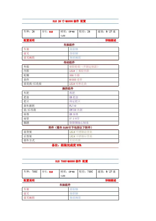
车种:26
型号:318
材质:CR-MO 4130
轮径:26
速别:9/27速
配置说明详细描述
车架组件
车架
铬钼钢
前叉
铬钼钢
前叉碗组
轴承碗组
传动组件
外胎
朝阳轮胎(开朗定制款)
内胎
LKLM丁基胶内胎
轮圈
36H车圈
套件
M4000套件
前花鼓/后花鼓
LKLM培林花鼓
操控组件
车把
燕把
把套
SR把套
把立
固定把立
刹车握把
FL740
前/后吊刹
CR720吊刹
座垫
SR座垫
座管
27.2座管
脚踏
铬钼钢轴心轴承
附件(整车3180¥不包括以下附件)
前货架
LKLM不锈钢前货架
后货架
LKLM不锈钢后货架
刹车方式
左后右前
备注:组装完成度95%
318 700C-M4000套件 配置
车种:700C
型号:318
材质:CR-MO 4130
轮径:700C
速别:9/27速
配置说明详细描述
车架组件
车架铬钼钢前叉铬钢前叉碗组轴承碗组
传动组件
外胎
朝阳轮胎(开朗定制款)
内胎
LKLM丁基胶内胎
轮圈
36H车圈
套件
M4000套件
前花鼓/后花鼓
LKLM培林花鼓
操控组件
车把
燕把
把套
SR把套
把立
固定把立
刹车握把
FL740
前/后吊刹
CR720吊刹
MB3180,3280,3480
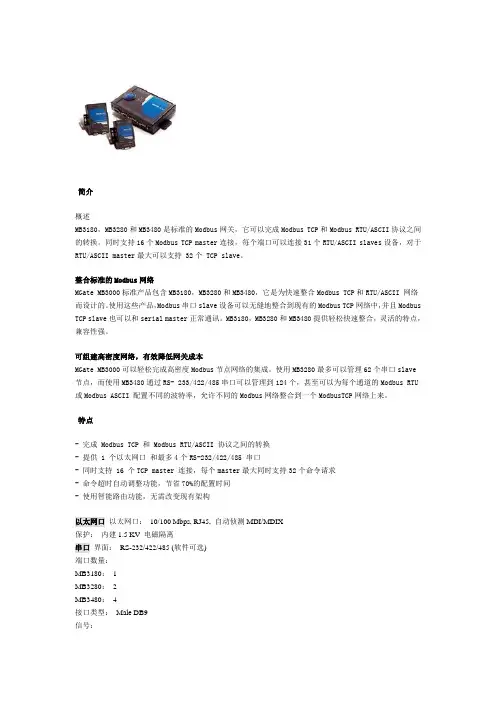
简介概述MB3180,MB3280和MB3480是标准的Modbus网关,它可以完成Modbus TCP和Modbus RTU/ASCII协议之间的转换。
同时支持16个Modbus TCP master连接,每个端口可以连接31个RTU/ASCII slaves设备,对于RTU/ASCII master最大可以支持 32个 TCP slave。
整合标准的Modbus网络MGate MB3000标准产品包含MB3180,MB3280和MB3480,它是为快速整合Modbus TCP和RTU/ASCII 网络而设计的。
使用这些产品,Modbus串口slave设备可以无缝地整合到现有的Modbus TCP网络中,并且Modbus TCP slave也可以和serial master正常通讯。
MB3180,MB3280和MB3480提供轻松快速整合,灵活的特点,兼容性强。
可组建高密度网络,有效降低网关成本MGate MB3000可以轻松完成高密度Modbus节点网络的集成。
使用MB3280最多可以管理62个串口slave节点,而使用MB3480通过RS- 233/422/485串口可以管理到124个,甚至可以为每个通道的Modbus RTU 或Modbus ASCII 配置不同的波特率,允许不同的Modbus网络整合到一个ModbusTCP网络上来。
特点- 完成 Modbus TCP 和 Modbus RTU/ASCII 协议之间的转换- 提供 1 个以太网口和最多4个RS-232/422/485 串口- 同时支持 16 个TCP master 连接,每个master最大同时支持32个命令请求- 命令超时自动调整功能,节省70%的配置时间- 使用智能路由功能,无需改变现有架构以太网口以太网口:10/100 Mbps, RJ45, 自动侦测MDI/MDIX保护:内建1.5 KV 电磁隔离串口界面:RS-232/422/485 (软件可选)端口数量:MB3180:1MB3280:2MB3480:4接口类型:Male DB9信号:RS-232:TxD, RxD, RTS, CTS, DTR, DSR, DCD, GNDRS-422:Tx+, Tx-, Rx+, Rx-, GNDRS-485 (2线):Data+, Data-, GNDRS-485 (4线):Tx+, Tx-, Rx+, Rx-, GND串口线保护:全信号15 KV ESD串口通讯参数校验位:None, Even, Odd, Space, Mark数据位:7, 8停止位:1, 2流控:RTS/CTS, XON/XOFF速率:50 ~ 921.6 Kbps软件特点操作模式:RTU Slave, RTU Master, ASCII Slave, ASCII Master工具:MGate Manager Suite for Windows 98/ME/NT/2000/XP/2003/Vista多master、多点连接:Master 模式:最大32 TCP slaveSlave 模式:16 TCP masters, 每个master允许同时32个命令请求电源需求电源输入:12 ~ 48 VDC电源接口:MB3180:power jackMB3280:power jackMB3480:power jack带有紧固螺丝和接线端子电源线保护:1 KV Burst (EFT), EN61000-4-40.5 KV Surge, EN61000-4-5机械规格外壳材料:MB3180:铝制(1 mm)MB3280:铝制(1 mm)MB3480:SECC钢板(0.8 mm)使用环境操作温度:0 ~ 55˚C (32 ~ 131˚F), 5 ~ 95% RH储存温度:-20 ~ 85˚C (-4 ~ 185˚F), 5 ~ 95% RH安规认证EMC:CE:EN550022 Class A / EN550024FCC:FCC Part 15 subpart B, Class A安全标准:TUV:EN60950-1冲击:IEC60068-2-27跌落:IEC60068-2-23振动:IEC60068-2-6保修期5 年可选型号产品编号描述MGate MB31801口标准Modbus网关MGate MB32802口标准Modbus网关MGate MB34804口标准Modbus网关。
GE Fanuc RX3i PACSystem 919-535-3180 产品说明说明书
Rx3i PacSystem919-535-3180*******************GE Fanuc IC695NKT002/automation/ge-fanuc/rx3i-pacsystem/IC695NKT002RX3i Ethernet NIU Kit with two Ethernet modules. IC695N IC695NKIC695NKTPACSystems* RX3iIC695NIU001 PLUSGFK-2598 Ethernet Network Interface UnitMarch 2011The PACSystems * RX3i Ethernet NIU PLUS,IC695NIU001, makes it possible to use PACSystems RX3i and Series 90-30 I/O remotely on an Ethernet network. Once set up by configuration, data exchange is completely automatic. System control can be provided by any master device capable of exchanging Ethernet Global Data (EGD). The Ethernet NIU automatically provides the controller with status information in each exchange. The application program logic in the controller can monitor this status data, and issue appropriate commands to the Ethernet NIU.▪ ▪ ▪ ▪ ▪ ▪ ▪see the Manual, GFK-2314.▪ ▪ storage.▪ ▪ ▪ RS-232 serial port.▪ based Ethernet Interface module (IC695ETM001) ▪ Data exchange using EGD▪ TCP/IP communication services using SRTP ▪Comprehensive station management/diagnostic tools*indicates a trademark of GE Intelligent Platforms, Inc. and/or its affiliates. All other trademarks are the property of their respective owners.▪ Supports operation with redundant controllers▪ PACSystems RX7i and RX3i controllers can sendselected COMMREQs to the RX3i ENIU via EGD. The ENIU executes the COMMREQs and returns the results to the controller.▪ During EGD configuration, RX3i Ethernet interfaces are identified by their Backplane/Slot locations.▪Supports display of module hardware revision, serial number and date code in Machine Edition Logic Developer software.GFK-2598Ethernet Global Data FeaturesThe Ethernet NIU communicates with its controller via EGD exchanges. One exchange is used to send outputs to the ENIU and another exchange is used to send inputs back to the controller. The ENIU supports receiving outputs from redundant controllers. By sending the EGD exchange to a group address both controllers can receive the inputs. Up to 1300 bytes of outputs can be sent to a set of ENIUs from a controller. Each ENIU can send up to 1300 bytes of inputs to the controller.A typical system might consist of a controller with five ENIUs. The controller sends 1300 bytes of outputs and each ENIU sends 100 bytes of inputs to the controller. This typical system would have its I/O updates occur in less than 25 milliseconds. If the controller scan time is greater than 25 milliseconds, the update occurs at the controller’s scan rate. This performance timing is a guideline, not a guarantee, and assumes that there is no other traffic on the Ethernet link to the I/O. Performance data for other system configurations can be found in the Ethernet NIU User’s Manual, GFK-2439. Ethernet NIU COMMREQ SupportThe Ethernet NIU supports COMMREQs that are sent to it by a C block application in a PACSystems RX7i or RX3i controller. This feature is not available with other types of controllers. Ladder code in the RX7i or RX3i CPU interfaces to the C block. The C block sends COMMREQ commands to the Ethernet NIU in an Ethernet Global Data Exchange. The Ethernet NIU executes the COMMREQ and sends the results back to the RX7i or RX3i using another EGD exchange. The following COMMREQs can be sent in this way:▪Modbus Master – function codes 1, 2, 3, 4, 5, 6, 7, 15, 16, 17▪Genius – enable/disable outputs, switch BSM, clear fault, clear all faults, assign monitor, read diagnostic▪PROFIBUS Master – COMMREQs 1, 2, 4, 5, 6▪Motion (DSM314/DSM324) – load parameters▪High Speed Counter – Data command▪DeviceNet Master – COMMREQs 1, 4, 5, 6, 7, 9▪Analog Module – HART Protocol COMMREQs.In addition, any COMMREQ supported by a module in the Ethernet NIU can be sent as a Generic COMMREQ, with the exception of DeviceNet Master Send Extended Explicit Message. For more information, see the PACSystems RX3i Ethernet NIU User’s Manual, GFK-2439.For environmental specifications and compliance to standards (for example, FCC or European Union Directives), refer to the PACSystems RX3i Hardware and Installation Manual, GFK-2314.GFK-2598Note: For Conformal Coat option, please consult the factory for price and availability.NIU Plus Battery and Switch LocationsFront View Rear ViewGFK-2598 SwitchesThe Ethernet NIU Plus has two switches. The Reset switch is not used. The three-position Run/Stop switch is located behind the protective door, as shown above.Unlike the Run/Stop switch on a CPU module, on an Ethernet NIU the use of this switch is disabled by default. If the switch is to be used to control the Run or Stop mode operation of the NIU, clear faults, and/or prevent writing to program memory or configuration, it must be enabled on the Settings Tab of the Ethernet NIU configuration in the folder, and stored to the ENIU.Stop, I/O DisabledStop, I/O EnabledReal Time Clock BatteryThe NIU Plus is shipped with a real time clock (RTC) battery (IC690ACC001) installed, with a pull-tab on the battery. The pull-tab should be removed before installing the module.The RTC battery has an estimated life 5 years. Battery must be replaced every 5 years on a regular maintenance schedule.GFK-2598Important Product Information for this ReleaseThe NIU001 Plus is a drop-in replacement for the NIU001 Classic module, with no changes to configuration, logic or wiring required. For new features and problems resolved, see page 6.UpgradesNIU001 Plus firmware upgrades are not compatible with NIU001 Classic hardware.GFK-2598NIU001+ Problems Resolved by Release 6.80SVC_REQ 57: Logic Driven Write to Nonvolatile Storage: In previous versions of the firmware, writing a partial block of word memory would result in incorrect data being written.For example:∙%R1 to %R10 are written to flash using SVC_REQ 57∙The values of %R3, %R4, %R6 changes∙%R1 to %R10 are again written to flash using SVC_REQ 57. The actual values written to flash will be incorrect.If all of the values, %R1 through %R10 have changed, the correct values would be written to flash.This issue has been fixed in firmware version 6.80New Features in Release 6.80∙This release enables support that is functionally identical to the IC695NIU001 on the new IC695NIU001+.∙The hardware revision, serial number and date code of the Ethernet NIU IC695NIU001+ can be displayed after upgrading to Proficy Machine Edition version 6.5 or later. To access this information, select Online Commands, Show Status and then click the Details button.GFK-2598GFK-2598GFK-2598GFK-2598GFK-2598GFK-2598User Manual UpdatesThe following information will be included in the next scheduled revision of the PACSystems CPU Reference Manual,GFK-2222.SVC_REQ 57: Logic Driven Write to Nonvolatile StorageThe following paragraphs will be added to the discussion of SVC_REQ 57 on page 9-59 of the CPU Reference Manual.This feature uses 65,536 bytes of nonvolatile storage. But not all of this memory is available for the actual data being written by the service request. Some of the memory is used internally by the PLC to maintain information about the data being stored.You can generally make the most efficient use of nonvolatile storage by transferring data in 56-byte increments, since this will actually write 64 bytes to the device. Given the bookkeeping overhead required by the PLC and possiblefragmentation, at least 54,912 bytes and no more than 64,000 bytes will be available for the reference data and the 8 bytes of command data for each invocation. For additional information on fragmentation see page 9-12.FragmentationDue to the nature of the media in PACSystems CPUs, writes may produce fragmentation of the memory. That is, small portions of the memory may become unavailable, depending upon the sequence of the writes and the size of each one.Data is stored on the device in 128 512-byte sections. Each section uses 12 bytes of bookkeeping information, leaving a maximum of 64,000 bytes devoted to the reference data and command data for each invocation. However, the data for a single invocation cannot be split across sections. So, if there is insufficient space in the currently used section to contain the new data, the unused portion of that section becomes lost. For example, suppose that the current operation is writing64 bytes of reference data and 8 bytes of command data (72 bytes total). If there are only 71 bytes remaining in the currentsection, the new data will be written to a new section and the unused 71 bytes in the old section become unavailable.RX3i I/O Module Sweep Impact TimesThe following table will be added to the RX3i sweep impact data on page A-22 of the CPU Reference Manual.DSM314 Scan Time Contribution in milliseconds.UL Class 1 Division 2 & ATEX Zone 2 Hazardous Area Warnings1. EQUIPMENT LABELED WITH REFERENCE TO CLASS I, GROUPS A, B, C, D, DIV. 2 HAZARDOUS AREAS ISSUITABLE FOR USE IN CLASS I, DIVISION 2, GROUPS A, B, C, D OR NON–HAZARDOUS LOCATIONS ONLY.2. WARNING – EXPLOSION HAZARD – SUBSTITUTION OF COMPONENTS MAY IMPAIR SUITABILITY FORCLASS I, DIVISION 2 & ATEX ZONE 2.3. WARNING – EXPLOSION HAZARD – DO NOT DISCONNECT EQUIPMENT UNLESS POWER HAS BEENSWITCHED OFF OR THE AREA IS KNOWN TO BE NON–HAZARDOUS.ATEX Zone 2 Hazardous Area RequirementsIn order to maintain compliance with the ATEX Directive, a RX3i system located in a Zone 2 area (Category 3) must be installed within a protective enclosure meeting the criteria detailed below:∙IP54 or greater, and∙Mechanical strength to withstand an impact energy of 3.5 Joules。
318通用规格说明说明书
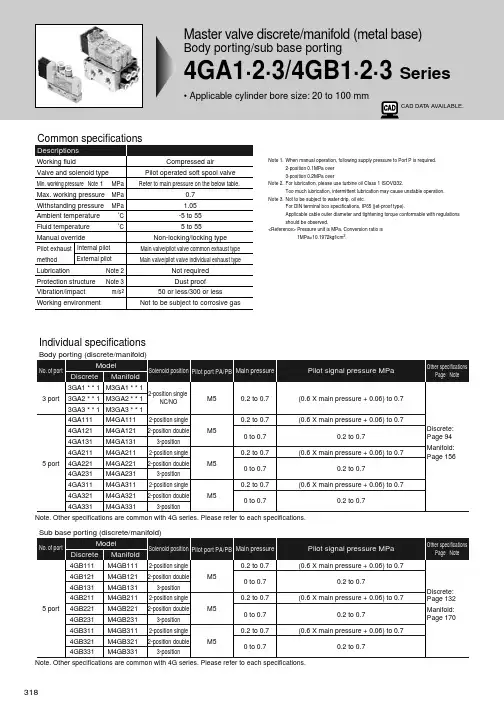
Discrete master valve of manifold (gasket/set screw attached)
4GA2 1 8 C4 H
Model Body porting Sub base porting
A Solenoid position Model
4GA2 1 1 C4 H
A Solenoid position Model
B Port size
C Options
Precautions for model selection
Note 1. For 3GA *, port is plugged. Note 2. For 3-position all ports closed and PAB connection,
Max. working pressure MPa
0.7
Withstanding pressure MPa
1.05
Ambient temperature ˚C
-5 to 55
Fluid temperature
˚C
5 to 55
Manual override
Pilot exhaust Internal pilot
Not required
Protection structure Note 3
Dust proof
Vibration/impact
m/s2
50 or less/300 or less
Working environment
Not to be subject to corrosive gas
Note 1. When manual operation, following supply pressure to Port P is required. 2-position 0.1MPa over 3-position 0.2MPa over
mx-m318部品手册
2 XEBS730P08000
3 DHAI-0503QSPZ
4 CPWBN0198QSE5
5 MSPRP3009FCZZ
6 LHLDZ0119QSZZ
7 VVL81HB1T03-A 8 LHLDZ0118QSZZ
9 PSHEZ5764FCZZ 10 HPNLH0264FCZZ 11 CFILW0018QS04 12 PSHEZ5392FCZ1
AF
C
AC
CHale Waihona Puke AECBS
E
AD
C
AK
C
BV
B
AL
C
AC
C
CE
D
AL
D
AB
C
AC
C
AY
D
AD
C
AD
B
AR
D
AP
D
AG
D
AK
D
AH
D
AF
D
AN
D
AY
E
AE
C
AF
C
AX
C
AA
C
BZ
E
CE
E
CE
E
中文名称 电路板保护贴片 螺钉 按键电路板线缆 OPU 电路板 LCD接地弹簧 LCD固定B AD2 LCD LCD固定A AD2 触控面板贴片 触控面板 滤板 滤板贴片 B 滤板贴片 A 操作面板 面板连接固定 LED 镜头 AD2 模式键 AD2 数字键 -AS C 键 AS 复印键套环 CA 键套 AS CA 键 -AS 复印键 ASAD2 按键电路板 LCD P FFC
13 PSHEZ5391FCZ1 15 CPNLC0054QS02 16 LHLDZ1885FCZZ 17 PLNS-0012QSZZ
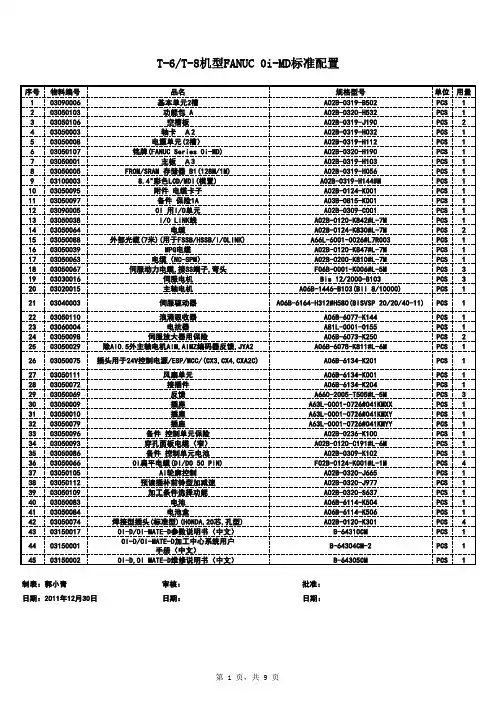
发那科标准配置
莫萨公司MGate MB3180 MB3280 MB3480系列1、2和4端口标准串行到以太网Mod
MGate MB3180/MB3280/MB3480Series1,2,and4-port standard serial-to-Ethernet Modbus gatewaysFeatures and Benefits•Supports Auto Device Routing for easy configuration•Supports route by TCP port or IP address for flexible deployment•Converts between Modbus TCP and Modbus RTU/ASCII protocols•1Ethernet port and1,2,or4RS-232/422/485ports•16simultaneous TCP masters with up to32simultaneous requests permaster•Easy hardware setup and configurationCertificationsIntroductionThe MB3180,MB3280,and MB3480are standard Modbus gateways that convert between Modbus TCP and Modbus RTU/ASCII protocols.Up to 16simultaneous Modbus TCP masters are supported,with up to31RTU/ASCII slaves per serial port.For RTU/ASCII masters,up to32TCP slaves are supported.Routing through the serial ports can be controlled by IP address,TCP port number,or ID mapping.Serial-port routing by TCP port and IP address allows access for up to4TCP clients/masters(MB3280/MB3480models),while routing by ID mapping allows access for up to16 TCP clients/masters(MB3180/MB3280/MB3480).Standard Modbus Network IntegrationThe three standard MGate™models(MB3180,MB3280,and MB3480)are designed for easy integration of Modbus TCP and RTU/ASCII networks. With these models,Modbus serial slave devices can be seamlessly incorporated into an existing Modbus TCP network,and Modbus TCP slaves can be made accessible to serial masters.The MB3180,MB3280,and MB3480offer features that make network integration easy,customizable, and compatible with almost any Modbus network.High Density,Cost-Effective GatewaysThe MGate™MB3000gateways can effectively connect a high density of Modbus nodes to the same network.The MB3280can manage up to62 serial slave nodes,and the MB3480can manage up to124serial slave nodes.Each RS-232/422/485serial port can be configured individually for Modbus RTU or Modbus ASCII operation and for different baudrates,allowing both types of networks to be integrated with Modbus TCP through one Modbus gateway.Auto-Device Routing for Easy Configuration(patented)Moxa’s Auto-Device Routing function helps eliminate many of the problems and inconveniences encountered by engineers who need to configure large numbers of Modbus devices.A single mouse click is all that’s required to set up a slave ID routing table and configure Modbus gateways to automatically detect Modbus requests from a supervisory control and data acquisition(SCADA)system.By removing the need to manually create the slave ID routing table,the Auto-Device Routing function saves engineers significant time and cost.SpecificationsEthernet Interface10/100BaseT(X)Ports(RJ45connector)Auto MDI/MDI-X connectionMagnetic Isolation Protection 1.5kV(built-in)Ethernet Software FeaturesIndustrial Protocols Modbus TCP Client(Master)Modbus TCP Server(Slave)Configuration Options All models:Web Console(HTTP),Device Search Utility(DSU),MGate Manager,MCCTool,Telnet ConsoleMGate MB3280/MB3480only:Web Console(HTTPS)Management All models:ARP,DHCP Client,DNS,HTTP,SNMPv1/v2c/v3,TCP/IP,Telnet,UDPMGate MB3280/MB3240only:HTTPS,SMTP,SNMP Trap,NTP ClientMIB RFC1213,RFC1317Time Management NTP Client(MGate MB3180Excluded)Security FunctionsAuthentication Local databaseEncryption HTTPSAES-128AES-256SHA-256Security Protocols SNMPv3HTTPS(TLS1.2)(except MGate MB3180)Serial InterfaceNo.of Ports MGate MB3180:1MGate MB3280:2MGate MB3480:4Connector DB9maleSerial Standards RS-232/422/485(software selectable)Baudrate50bps to921.6kbpsData Bits7,8Parity NoneEvenOddSpaceMarkStop Bits1,2Flow Control DTR/DSRRTS Toggle(RS-232only)RTS/CTSRS-485Data Direction Control ADDC(automatic data direction control)Pull High/Low Resistor for RS-4851kilo-ohm,150kilo-ohmsTerminator for RS-485MGate MB3180:NoneMGate MB3280/MB3480:120ohmsSerial SignalsRS-232TxD,RxD,RTS,CTS,DTR,DSR,DCD,GNDRS-422Tx+,Tx-,Rx+,Rx-,GNDRS-485-2w Data+,Data-,GNDRS-485-4w Tx+,Tx-,Rx+,Rx-,GNDSerial Software FeaturesIndustrial Protocols Modbus RTU/ASCII MasterModbus RTU/ASCII SlaveModbus(Transparent)Max.No.of Client Connections16Max.No.of Server Connections32Power ParametersInput Voltage12to48VDCInput Current MGate MB3180:200mA@12VDCMGate MB3280:250mA@12VDCMGate MB3480:365mA@12VDCPower Connector MGate MB3180:Power jackMGate MB3280/MB3480:Power jack and terminal blockPhysical CharacteristicsHousing MetalIP Rating IP301Dimensions(with ears)MGate MB3180:22x75x80mm(0.87x2.95x3.15in)MGate MB3280:22x100x111mm(0.87x3.94x4.37in)MGate MB3480:35.5x102.7x181.3mm(1.40x4.04x7.14in)Dimensions(without ears)MGate MB3180:22x52x80mm(0.87x2.05x3.15in)MGate MB3280:22x77x111mm(0.87x3.03x4.37in)MGate MB3480:35.5x102.7x157.2mm(1.40x4.04x6.19in)Weight MGate MB3180:340g(0.75lb)MGate MB3280:360g(0.79lb)MGate MB3480:740g(1.63lb)Environmental LimitsOperating Temperature MGate MB3180:0to55°C(32to131°F)MGate MB3280:0to60°C(32to140°F)MGate MB3480:0to55°C(32to131°F)Storage Temperature(package included)-40to85°C(-40to185°F)Ambient Relative Humidity5to95%(non-condensing)Standards and CertificationsEMC EN55032/35EMI CISPR32,FCC Part15B Class AEMS IEC61000-4-2ESD:Contact:4kV;Air:8kVIEC61000-4-3RS:80MHz to1GHz:3V/mIEC61000-4-4EFT:Power:1kV;Signal:0.5kVIEC61000-4-5Surge:Power:1kV(MB3180/MB3280)IEC61000-4-5Surge:Power:1kV;Signal:2kV(MB3480)IEC61000-4-6CS:3VIEC61000-4-8PFMFIEC61000-4-11Safety MB3180Models:EN62368-1and UL60950-1MB3280/3480Models:IEC/UL62368-11.For the MGate MB3480,the two screws provided with the wall-mounting kit must be used to fasten the kit to the bottom of the MGate,and the MGate must beproperly attached to the terminal block for power input.MTBFTime MGate MB3180:2,762,384hrsMGate MB3280:749,455hrsMGate MB3480:1,213,993hrsStandards Telcordia SR332WarrantyWarranty Period5yearsDetails See /warrantyPackage ContentsDevice1x MGate MB3180/MB3280/MB3480Series gatewayPower Supply1x power adapter,suitable for your regionDocumentation1x quick installation guide1x warranty cardDimensionsOrdering InformationModel Name No.of Serial Ports MGate MB31801MGate MB32802MGate MB34804 Accessories(sold separately)CablesCBL-F9M9-150DB9female to DB9male serial cable,1.5mCBL-F9M9-20DB9female to DB9male serial cable,20cmConnectorsMini DB9F-to-TB DB9female to terminal block connectorDIN-Rail Mounting KitsDK35A DIN-rail mounting kit,35mmWall-Mounting KitsWK-35-01Wall-mounting kit with2plates(35x44x2.5mm)and6screws©Moxa Inc.All rights reserved.Updated Aug07,2023.This document and any portion thereof may not be reproduced or used in any manner whatsoever without the express written permission of Moxa Inc.Product specifications subject to change without notice.Visit our website for the most up-to-date product information.。
CA3106B18-8PX中文资料
28-11
18 - #16 (A-I, N-X) 4 - #12 (J-M)
28-12
26 - #16
28-15
35 - #16
28-16
20 - #16
28-21
37 - #16
36-5
4 - #0
36-7
40 - #16 (A-Z, a-s) 7 - #12 (t-z)
36-8
46 - #16 (A-X, Z-z) 1 - #12 (Y)
18-10
4 - #12
18-11
5 - #12
18-12
6 - #16
18-20
5 - #16
18-22
3 - #16
20-3
3 - #12
20-4
4 - #12
20-7
8 - #16
20-19
3 - #8
20-27
14 - #16
20-29
17 - #16
20-33
11 - #16
22-2
3 - #8
2 - #12
16S-1
7 - #16
16S-8
5 - #16
18-1
10 - #16
18-4
4 - #16
18-5
1 - #16 (A) 2 - #12 (B, C)
18-8
7 - #16 (A-G) 1 - #12 (H)
18-9
5 - #16 (B, C, E-G) 2 - #12 (A, D)
Contact Arrangement 14S-9 16-9 16-10 16-11 16S-1 16S-8 18-1 18-4 18-5 18-8 18-9 18-10 18-11 18-12 18-20 18-22 20-3 20-4 20-7 20-19 20-27 W˚ 70 35 90 35 80 — 70 35 80 70 80 — — 80 90 70 70 45 80 90 35 X˚ 145 110 180 110 — 170 145 110 110 — 110 120 170 — 180 145 145 110 110 180 110 Y˚ 215 250 270 250 — 265 215 250 250 — 250 240 265 — 270 215 215 250 250 270 250 Z˚ 290 325 — 325 280 — 290 325 280 290 280 — — 280 — 290 290 — 280 — 325 Contact Arrangement 20-29 20-33 22-2 22-14 22-19 22-23 22-28 24-2 24-10 24-20 24-28 28-10 28-11 28-12 28-15 28-16 28-21 36-5 36-7 36-8 36-10 W˚ 80 35 70 80 80 35 80 80 80 80 80 80 80 90 80 80 80 — 80 80 80
MGC310_MGC320中文说明书
MGC310/MGC320 发电机组控制器用户手册目录前言 ......................................................................................................................... 错误!未定义书签。
1 概述 (4)2 性能特点 (5)3 规格参数 (6)4 操作 (7)4.1 前面板描述 (7)4.2 按键功能描述 (8)4.3 LCD图标描述 (9)4.4 显示描述 (10)5 保护 (13)6 接线 (14)7 编程参数范围及定义 (16)7.1 参数设置内容及范围一览表 (16)7.2 可编程输出口可定义内容一览表 (18)7.3 可编程输入口定义内容一览表 (18)7.4 传感器选择 (19)8 控制器参数设置 (20)9 传感器设置 (21)10 试运行 (22)11 典型应用图 (23)12 安装 (24)12.1 卡件 (24)12.2 外形及开孔尺寸 (24)13 故障排除 (25)表1 版本发展历史1 概述MGC300系列发电机组控制器可用于单台发电机组自动化控制,可实现单机自起动/AMF。
该系列控制器集成了数字化、智能化,采用液晶(LCD)图形显示器,操作简单,运行可靠。
MGC300系列发电机组控制器采用32位微处理器技术,实现了多种参数的精密测量、定值调节以及定时、阈值整定等功能,绝大部分参数可从控制器前面板调整,所有参数可使用PC机通过RS485接口调整。
其结构紧凑、接线简单、可靠性高,可广泛应用于各类型发电机组自动化系统。
MGC300系列发电机组控制器控制器分为真低功耗(电源断电)和伪低功耗(被唤醒,但控制器屏幕不亮,只有停机灯闪烁,也不执行任何动作)。
2 性能特点——图案型LCD显示(带背光)、LED灯指示、轻触按钮操作;——屏幕保护采用硬屏亚克力材料;——供电电源范围宽DC (8~35)V,能适应不同的起动电池电压环境;——采集并显示市电/发电三相电压、三相电流、频率、功率参数;市电线电压L12,L23,L31 相电压L1,L2,L3 频率Hz 发电线电压L12,L23,L31 相电压L1,L2,L3 频率Hz负载电流Ia,Ib,Ic 总有功功率P 单位:A 单位:kW——市电具有过压、欠压、过频、欠频、缺相功能,发电具有过压、欠压、过频、欠频、过流、过功率、缺相功能;——精密采集发动机的各种参量:温度°C 燃油位%电池电压V 累计运行时间H(最多199999小时)转速RPM 累计开机次数(最多199999次,仅能通过上位机显示)——机组故障保护及显示功能;——控制器具有4种工作模式:手动、自动、停机、试机模式,其中MGC310具有停机、手动、自动模式,MGC320具有手动、自动、停机、试机模式;——参数设置功能:允许用户对其参数进行更改设定,在系统掉电时也不会丢失。
GE Fanuc RX3i PACSystem 919-535-3180 产品说明说明书
Rx3i PacSystem919-535-3180*******************GE Fanuc IC694BEM320/automation/ge-fanuc/rx3i-pacsystem/IC694BEM320RX3i Communication Module, I/O Link Interface Module (Slave). IC694B IC694BE IC694BEM14-14 PACSystems™ RX3i System Manual – October 2005 GFK-2314CI/O Link Interface Module: IC694BEM320The RX3i I/O Link Interface Module operates as a slave on a Fanuc I/O Link network. It can exchange either 32 or 64 inputs and outputs with the master. Typical masters on the I/O Link include all modern FANUC CNCs and Power Mates, PACSystems controllers and Series 90 PLCs equipped with an I/O Link Master Module.An I/O Link Interface Module occupies one module slot in anRX3i backplane. It can be installed in any available backplaneslot.The maximum number of I/O Link Interface Modules that can beinstalled in the backplane depends on the power that is availablefrom the power supply. To determine the exact number ofmodules allowed in your system, see the information on powersupplies in chapter 3.Usually, when there are multiple I/O Link Interface Modules in thesame RX3i system, they are on separate I/O Links. However, itis possible to have more than one I/O Link Interface Module inthe system connected to the same link, if that suits the needs ofthe application.Module SpecificationsModule typeSeries 90–30 PLC module, providing I/O Link communications with I/O master. LEDsOK, RDY I/O Points32 or 64, jumper selectable +5V currentwithout Optical Adapter connected: 205mA with Optical Adapter: 405 mAUser ManualRX3i I/O Link Interface Modules User’s Manual , GFK-2358GFK-2314C Chapter 14 Special-Purpose Modules 14-15 Module DescriptionThe module’s front cover is removable. A jumper plug inside the front cover is used to set up the module as a 32–point or 64–point I/O module. The factory default is 32.64 I/O 323 21JP1 To select 32 inputs and outputs, the jumper should be on the top and middle pins as shown at left. To select 64 inputs and outputs, the jumper should be on the middle andbottom pins.LEDsThe module has two LEDS that show its operating, and communications status.OK:indicates the module’s operating status. RDY: indicates the module’s communications status.After power–up, the OK LED should remain ON. The RDY LED turns ON after the I/O Link master has established communications with the module.Serial PortsThe front of the module has two 20–pin connectors that are used to attach the I/O Link cable. One connector is for the cable to the previous device on the link––either the master or another slave. The other connector is for the cable to the next slave on the link, if there is one. See the RX3i I/O Link Modules User’s Manual , GFK-2358 for more information. Signal levels are RS422/485 compatible.。