INCORPORATING CAD FOR MEMS TOOLS INTO THE ACADEMIC ENVIRONMENT
关于Microstation与AutoCAD数据转换方法的研究
关于Microstation与AutoCAD数据转换方法的研究1、相关定义1.1、元数据的定义元数据,最常见的定义是:”关于数据的数据”(Data about data) [14]。
更准确一点说: 元数据是描述流程、信息和对象的数据[15]。
这些描述涉及像技术属性(例如,结构和行为)这样的特征、业务定义(包括数据字典和分类法)以及操作特征(如活动指标和使用历史)。
1.2、多维数据模型概念石油基础数据数据仓库的主要功能是提供复杂的联机分析处理操作,而多维数据模型可以快速地解决多维数据的存储与度量值之间的关系,从而有效地对数据进行深层次的分析[27]。
下面从不同角度定义石油基础数据数据仓库多维数据模型。
[定义5-1]:石油基础数据数据仓库多维数据模型即多维数据立方体,它的数据集合定义为一个4元组关系,其中: (1)W表示m个维的集合,即W={w1,w2,w3, ,wm},wi为从域domdim(i) 中抽取的维名; (2)D表示n 个度量的集合,即D={d1,d2,d3, ,dn},其中mi表示从域dommeasure(i) 的度量中抽取的度量名; (3)S表示k个属性的集合,即S={s1,s2,s3, ,sk},其中si为从域domattribute(i) 中抽取的属性名; (4)一对多映射f,表示每个维对应一个属性集合。
不同维之间对应的属性集合交集为0,即i,j,i j,f(wi)∩f(wj)=0; (5)度量集合D与维集合W的交集为0,即D∩W=0;44 (6)度量属性集合D依赖于维集合W,即W和D之间存在函数关系F:DOM(w1) × ×DOM(wn)→DOM(d1)× ×DOM(dk),其中DOM(wi)是维wi的值域,DOM(di)是度量属性的值域。
[定义5-2]:多维数据集的一个维是一个二元组w=(L,≤),其中L表示组成维w所有层的集合,≤是定义在L上的全序关系,满足对于任意li,lj∈L(1≤i≤n,1≤j≤n),或者有li≤lj或者有lj≤li成立[3]。
计算机辅助设计与计算机- AutoCAD (AutoCAD) 和计算机说明书

DOI: 10.17148/IARJSET.2021.8956AutoCAD and ComputerPrem ChandraJECRC University, Jaipur, Rajasthan, IndiaAbstract: Earlier manual drafting & design was carried out by using tools like scales, Compasses, protectors, T-square, Mini Drafter etc. For engineers and architects, it was time taking and not fit for repetitive design. After evolution of latest technologies and innovation in high end computers with development of software, designing & drafting becomes easier, accurate and faster. Manual drafting is now replaced by latest CAD Tools used with computers. One of the software applications for Computer Aided Design (CAD) & drafting is AutoCAD. It is very useful not only with engineering industry but many other industries too.Keywords: Computer Aided Design, AutoCAD software, drafting tool, Personal Computer, modelling, analysis.1.INTRODUCTIONIn the old days manual drafting method was used by architects and engineers. It was time taking process due to use of pen and papers. Nowadays industries are using Computer-Aided Design/Drafting systems with help of computers to design, drafting, modelling and even analysis too. These Computer Aided Design & Drafting tools replaced the manual drafting method. There are various software for design purpose in the market, but one of the most user friendly commercially CAD software is AutoCAD.2.WHAT IS AUTOCADThe word AutoCAD is made up of two words “Auto” (Logo of the Company) and “CAD” (Computer Aided Design /Drafting).It was first developed by USA based company Autodesk founded by Mr John Walker and launched in December 1982.AutoCAD application is designed to run on mini computers and personal computers. This CAD tool allowed the users to to create detailed technical drawings and was affordable to many smaller design, engineering and architecture companies. It was launched in 1988 in India. AutoCAD is a 2D and 3D modelling software which is used with help of Personal Computers. The first version of AutoCAD was R1 after that R2, R3,….. and upto R14.In year 2000, Autodesk launched a version of AutoCAD 2000 after that 2001, 2002….. and so on. The latest version is 2022, launched in March 2021.3.LITERATURE REVIEW“AutoCAD allows creation not just for normal drawing. Logically connected fragments can be placed on the allocated layers or grouped in compound objects. And we consider them as a whole entity. AutoCAD "remembers" position, size, color of the constructed objects and writes down this data in an internal database for their subsequent search, analysis, and processing. AutoCAD can function with a wide range of personal computers and graphic workstations under control of various operating systems [1], [2].”“AutoCAD is a powerful tool for automating graphical work based on personal computers. It gives the user possibilities which earlier could be realized only on big and expensive computing systems: any drawing that was drawn manually can be constructed with AutoCAD now. AutoCAD is capable to perform almost any kinds of graphic works [3], [4].”4.PRODUCTS AND ITS APPLICATIONSAutoCAD products are in the form of collections and are as follows:(a). Architecture, Engineering & Construction Collection (AEC): It provides designers, engineers and contractors a set of BIM and CAD tools supported by a cloud-based common data environment that facilitates project delivery from early-stage design through to construction.(b). Product Design and manufacturing collection (PDMC): It The collection is a powerful set of applications that provides extended capabilities to Inventor and AutoCAD for engineers who design complex and customised products, equipment and systems. It extends Inventor with add-ins for tolerance analysis, simulation and production layout. It use connected products for 2D drafting, large-scale design review and visualization &Connect to Fusion 360 to access next-generation capabilities and collaborationDOI: 10.17148/IARJSET.2021.8956(c). Media and Entertainment Collection: It includes all of the tools you need to build a powerful and scalable 3D animation pipeline for complex simulations, effects and rendering. It provides from detailed battle sequences to hyper realistic creatures, render your toughest projects with Arnold. It create complex effects including explosions, fire, sand and snow with Bi frost for Maya. It empower artists with a choice of tools to produce beautiful, film-quality work every time. Various top products are mentioned in table-1.Table.1. Top AutoCAD Products5.WHAT CAN IT DOAutoCAD screen is shown in Fig.-2 and its application in graphics design is shown in Fig.-1.Fig.-1.Application of AutoCADDOI: 10.17148/IARJSET.2021.8956Fig.-1. AutoCAD Screen6.BENEFITS OF AUTOCADIt allows to draw and edit digital 2D and 3D designs more quickly and easily. The files can also be easily saved and stored on cloud to access anywhere and anytime by the user.Following are the other major benefits:1). Modification point of view: In this application major benefit is to easily edit, change and manipulations in the design by using computer.2). Production point of view: In this we can create a reusable block library using window system to get easy access. For repetitive components we can use block library to increase the design efficiency and makes process faster.3). Accuracy point of view: In this we can create more accurate design and even very small size of components to be designed.4).Easy to prototype: Once the model is ready to use, we can feed it to 3D printer for rapid prototype5). It improves productivity in drafting & shorter preparation time required for drawing.6).It reduced manpower requirements &modifications in drawing are easier.7).It is more efficient operation in drafting & very low wastage in drawings.8). It maintains very good accuracy of drawing & easy in documentation.7. LIMITATION/DRAWBACK OF AUTOCADAs mentioned in above paragraph regarding benefits, but it has some limitations/drawback too. Which are as follows:(1). As we know that this software have many modules so it requires more space for installation and storage.(2). Large amount of memory required for better viewing of the graphics.(3). Huge investment for the software purchase.DOI: 10.17148/IARJSET.2021.89568. CONCLUSIONSAutoCAD is very power full tool for CAD purpose in engineering drawing and easy to use. It is useful in 2D & 3D both type of drawing. It can save the time for project. In latest version some analysis also is done.10. REFERENCES[1]Abbasov, I. B. (2007). Create computer drawings in AutoCAD 2007/2008. Мoscow: DMK Press.[2]Ozkaya, S. I. (2018). FRACOR-software toolbox for deterministic mapping of fracture corridors in oil fields on AutoCAD platform. Computers & Geosciences, 112, 9-22.[3]Nikulin, E. A. (2005).K omp’yuternaya geometriya i algoritmy mashinnoi grafiki (Computer Geometry and Algorithms of Computer Graphics), St. Petersburg: BKhV Peterburg..[4]Patpatiya, Parth and Sharma, Shailly and Bhatnagar, Varun and Tomar, Jyoti and Shalu, JyotiKumari, Approaches for Concising AutoCAD Files (September 2, 2019). Proceedings of International Conference on Advancements in Computing & Management (ICACM) 2019. [5]Mohd Rafeeq Ur Rahman, Mohammed Iqbal Khatib, P. Seema Rani, Shahin Shaikh, Gunashekar.G (2019). Effect of Computer Aided Drafting on Manual Drafting Skills. International Journal of Innovative Technology and Exploring Engineering (IJITEE) ISSN: 2278-3075, Volume-8 Issue-11.[6]Runmei Zhang1 and YehuanGu. (2017). Research on AutoCAD secondary development and function expansion based on VBA technology. 3rd International Conference on Advances in Energy, Environment and Chemical Engineering IOP Publishing IOP Conf. Series: Earth and Environmental Science 69 (2017).[7]Alexey L. Khoroshko. (2020). The Research of the Possibilities and Application of the AutoCAD Software Package for Creating Electronic Versions of Textbooks for “Engineering and Computer Graphics”. TEM Journal Volume 9, Issue 3, Pages 1141‐1149, ISSN 2217‐8309.[8]https://www.autodesk.in[9]Presentation on AutoCAD by Mr.Vaibhavgautam[10]Presentation:AutoCADSoftware by Mr.Waqas Ali, Source: .[11]J. A. JIMOH, (2019), COMPARATIVE EFFECTS OF 2D AND 3D METHODS OF GRAPHICS IN AUTOCAD ON INTEREST OF NATIONAL DIPLOMA STUDENTS IN ENGINEERING GRAPHICS IN SOUTH-WEST NIGERIA, International Journal of Educational Research Vol. 6, No 1, 2019.[12]Vinod C; Menaka D. "Computer Aided Detection of Nodule from Computed Tomography Images of Lung". International Research Journal on Advanced Science Hub, 3, Special Issue ICARD-2021 3S, 2021, 96-100. doi: 10.47392/irjash.2021.073。
classmate CAD 产品说明书
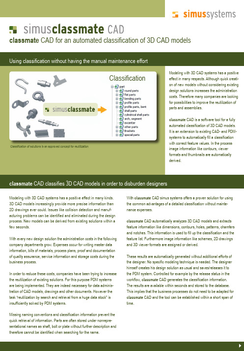
cation of solutions is an approved concept for reutilization Modeling with 3D CAD systems has a positive effect in many respects. Although quick creati-on of new models without considering existing design solutions increases the administration costs. Therefore many companies are looking for possibilities to improve the reutilization of parts and assemblies.classmate CAD is a software tool for a fully automated classifi cation of 3D CAD models. It is an extension to existing CAD- and PDM-systems to automatically fi ll a classifi cation with correct feature values. In the process image information like contours, viewer formats and thumbnails are automatically derived.classmate CAD classifi es 3D CAD models in order to disburden designersModeling with 3D CAD systems has a positive effect in many kinds. 3D CAD models increasingly provide more precise information than 2D drawings ever could. Issues like collision detection and manuf-acturing problems can be identifi ed and eliminated during the design process. New models can be derived from existing solutions within a few seconds.With every new design solution the administration costs in the following company departments grow. Expenses occur for writing master data information, bills of materials, process plans, proof and documentation of quality assurance, service information and storage costs during the business process.In order to reduce these costs, companies have been trying to increase the reutilization of existing solutions. For this purpose PDM systems are being implemented. They are indeed necessary for data adminis-tration of CAD models, drawings and other documents. However the task “reutilization by search and retrieval from a huge data stock” is insuffi ciently solved by PDM systems.Missing naming conventions and classifi cation information prevent the quick retrieval of information. Parts are often stored under nonrepre-sentational names as shaft, bolt or plate without further description and therefore cannot be identifi ed when searching for the name.With classmate CAD simus systems offers a proven solution for using the common advantages of a detailed classifi cation without mainte-nance expenses.classmate CAD automatically analyzes 3D CAD models and extracts feature information like dimensions, contours, holes, patterns, chamfers and notches. This information is used to fi ll up the classifi cation and the feature list. Furthermore image information like schemes, 2D drawings and 3D viewer formats are assigned or derived.These results are automatically generated without additional efforts of the designer. No specifi c modeling technique is needed. The designer himself creates his design solution as usual and saves/releases it to the PDM system. Controlled for example by the release status in the workfl ow, classmate CAD generates the classifi cation information. The results are available within seconds and stored to the database. This implies that the business processes do not need to be adapted for classmate CAD and the tool can be established within a short span of time.classmate CAD for an automated classifi cation of 3D CAD modelsClassifiClassifi cationclassmate CAD works with a highly effi cient rule base. This rule base is built out of the typical geometries existing in mechanical engineering and plant construction. Customer-specifi c requirements can be easily integrated into the rule base. Subsequently the 3D CAD models of the customer are analyzed in a batch process so that fi rst results are available in a few days.The geometrical classifi cation can be combined with a functional classi-fi cation. Any functional parameter (for example force, power, type) can be used to design additional classes and features.The presentation of the results depends on the used search client. Ifthe PDM- or ERP system does not have any module for storing classi-fi cation information simus systems offers the search client classmate FINDER. classmate FINDER provides various search and retrieval functions especially with detailed graphical information. Many standar-dized interfaces to existing ERP and PDM solutions already exist, e.g.: SAP Agile DBworks MaxxDBPDMWorks EnterpriseProductstream ProfessionalBasing the search on high-quality data a duplicate analysis can now be established easily. classmate FINDER includes an effective function for analyzing huge databases for duplicates. A classifi ed and simplifi ed database makes it easy to search for existing parts within seconds and therefore reutilization will increase extensively.Reutilization makes the database increase slower which results in considerable cost savings.Classifi cation with classmateCAD offers sophisticated search and retrieval functionsclassmate CAD automates the administration of classifi cation dataclassmate CAD offers the possibility to use an extensive customer-specifi c classifi cation with detailed feature lists without any additional effort for the designer. Automatically generated 3D viewer formats, thumbnails and schemes top off the function volume. If reasonable thegeometric classifi cation can be combined with an individually designed functional classifi cation. classmate CAD analyses the 3D CAD models independent of the modeling and does not need any further parameter lists or predefi ned features.simus systems GmbH | Haid-und-Neu-Straße 7 | 76131 Karlsruhe | Deutschland**********************||tel +49 (721) 83 08 43 -0 | fax +49 (721) 83 08 43 -77Your requirementsImprovement of transparency of product data Improved search options for the designers Quick retrieval of similar parts No additional effort for the designers Automatic fi lling of the classifi cation Automatic fi lling of the feature listAutomatic generation of viewer formats and thumbnails Elimination of duplicates Few expenses for the integration Short project durationAccurately defi ned project budgetOur offerAutomatic analysis of 3D CAD modelsAutomatic classifi cation of 3D CAD models into a customer specifi c classifi cation structure Automatic fi lling of customer-specifi c feature lists Possibility to combine a functional and a geometrical classifi cationA lot of interfaces to databases and systems, for example SAP PLM, Agile, Productstream Professional Subsequent extension of classifi cation structure Combination with the search client classmate FINDER Experience in projects with customers from small or medium-sized enterprises to huge corporationsWe are looking forward hearing from you.。
AutoCAD Electrical 实用教程:如何实施 AutoCAD Electrical说明书

IT10734Get Powered Up: How to Implement AutoCAD ElectricalTiffany BachmeierAutodeskRobert SteinAutodeskLearning Objectives•Discover the WD.ENV file•Discover AutoCAD Electrical intelligent blocks•Discover AutoCAD Electrical paths•Learn how to tie it all togetherDescriptionTired of clicking through the same paths several times a day just to get to default directories? Do you want to help yourself and others store files in the proper directories? This class is for you. We will discuss the WD.ENV and WD_M files used to initiate the AutoCAD Electrical software environment and provide default paths for various commands. We will also touch on templates and shared environments. Your AU ExpertsTiffany Bachmeier has been an Autodesk Consultant for the last decade. Herprimary focus is as a technical consultant/instructor for AutoCAD Electrical, but shealso focuses on AutoCAD, Inventor, and a variety of other products in the Autodeskfamily. She is an Autodesk Certified Instructor and she (and team) has won awardsfor developing a full line of online, live, instructor-led training classes for theAutodesk manufacturing products. Before becoming a consultant she earned herbachelor’s degree from Michigan State University (MSU) and she worked in many different industries gaining valuable CAD experience, including electrical engineering, interiordesign/architecture, mechanical engineering, software engineering, and she was part of MSU’s CAD Development Team. She started on AutoCAD R10 and has carried a strong passion for Autodesk products ever since.Based in Novi, Michigan, Robert Stein manages a team of data managementimplementation consultants for Autodesk, Inc., focusing on data management. Priorto working for Autodesk, Robert worked as a designer, CAD manager, andconsultant at a variety of companies. Robert has worked on a number of large-scaleimplementations and custom programming projects with Autodesk manufacturingproducts, including Inventor software, AutoCAD Electrical software, AutoCADMechanical software, and the Vault software family. Robert is in his 9th year as a presenter at Autodesk University.Learning Objective 1: Discover the WD.ENV fileOverview of the Environment File (wd.env)The wd.env file establishes the environment or default configuration for AutoCAD® Electrical commands and symbol searches. To configure the software for optimum results in a custom environment, you need to know what the file is, where it is located, and how to customize it.The Environment File DefinedThe wd.env environment file for AutoCAD Electrical provides the default search paths when the software searches for reference files or directory locations.The settings in the wd.env file can be overridden by settings within a project file. For example, changing the symbol library search path in the project properties overrides the settings in thewd.env file. However, clicking Default on the Project Settings dialog box returns the librarysearch paths to the settings from the wd.env file.You can create project-specific wd.env files. To create a project-specific file, copy the wd.env file and rename it to <projectname>.env. Then open the new file, make the desired project-specific changes, and save it.A sample of the settings available in the wd.env file is shown below.Note: To edit the wd.env file you must use an external ASCII editor such as Notepad. There are no tools or wizards for this purpose within AutoCAD Electrical.Location of the Environment FileThe default installation location for the wd.env file is:Windows Vista/7/8: C:\Users\{username}\Documents\Acade {version}\AeData.The software stores the path to the wd.env file in the wd_load.lsp file, which is located in theACADE directory. In a default installation this directory is located at:C:\Program Files\Autodesk\ AutoCAD {version}\AcadeThe wd_load.lsp file is loaded every time AutoCAD Electrical is started. If you change the location of the wd.env file, you need to edit the wd_load.lsp file to point to the new location. All environment files, including project-specific files, must be located in the same directory as specified by the wd_load.lsp file.The Environment File can also be moved to a different location by saving it in the new location with the same name (wd.env) and removing it from: C:\Users\{username}\Documents\Acade {version}\AeData\wd.env, then adding the new location to the top of your Support File Search Paths in the Options dialog box > Files Tab:Example of changing WD.ENV SettingYour company has created a custom symbol library directory located at W:\Custom Symbols. When you click the Browse button in the Insert Component dialog box, the Browse dialog box should open in this directory.Edit the wd.env file via any ASCII text editor (Notepad is one of the most commonly used programs), change the following line:*WD_INSCOMPDLG,x:/some path/,to override starting path for INS SCHEM COMP browse buttonThe new line should read as follows:WD_INSCOMPDLG,W:/Custom Symbols, to override starting path for INS SCHEM COMP browse button.Be sure to remove the leading asterisk and be sure to use the forward slash separator in thepath name.Simply activate a project to force the rereading of the wd.env file. Now, when the Browsebutton is selected, the W:/Custom Symbols directory is opened in the Browse window. Learning Objective 2: Discover AutoCAD Electrical Intelligent BlocksOverview of ACADE Intelligent BlocksCore AutoCAD® technology manages the symbol library system. Schematic and panel symbols are standard AutoCAD blocks that use attributes or xdata to store component information. The icon menu system for organizing, presenting, and retrieving the library symbols is easy to use.Because standard AutoCAD objects are used, there are no proprietary objects contained within the drawing. AutoCAD Electrical drawings are fully portable. They can be opened, viewed, and edited with no loss of functionality or integrity by any program that can recognize AutoCAD drawings.Schematic SymbolsA schematic symbol is a standard AutoCAD® block with specifically named attributes. Theseblocks are generic AutoCAD entities and you can use standard AutoCAD block and attributecreation commands to create them. Any schematic symbol that follows the naming convention and contain expected attributes are fully compatible with AutoCAD® Electrical.Symbols can be any size and width. You can use any type of AutoCAD object, such as polylinesand circles, for the graphical representation of the block. Custom-created blocks function thesame way as the supplied symbols. They break wires upon insertion and appear in the Bill ofMaterial, Component, and Wire Connection reports.One of the easiest ways to create a new symbol is to start with an existing library symbol. Inserta copy of a similar type, explode it, and then modify it to meet your requirements. Avoiddeleting the existing attribute definitions. Reposition and edit their default values as required.Then use Symbol Builder or AutoCAD to write a block to an external file (Wblock) to create your new symbol.TIPS•Keep all custom symbols that you create in a separate directory. Add the path to your custom symbol directory to the library search path.•Keep all objects on Layer 0 when creating a new block. During insertion,individual objects in the block are automatically moved to the layers set in thedrawing configuration.Symbol Naming ConventionA specific naming convention is used to enable some automation features. For example, the horizontal and vertical orientation of the symbol is specified by the first character, and the NO and NC state of the symbol is specified by the fifth character.The first character is either H or V for horizontal or vertical wire insertion, respectively.The next two characters are reserved for family type (for example, PB for push buttons, CR for control relays, LS for limit switches).The fourth character is generally a 2 for child contacts or a 1 for everything else (parent or stand-alone components).If the symbol is a contact, then the fifth character is a 1 for normally open or 2 for normally closed.Any additional characters are not specified in the naming convention. They are used to keep names unique.TIP•The fourth character of a block name has another special property. If the character is a 0 (zero), the wire number will not change as the wire passesthrough the component. This is true for any type of component or electricalblock name.Symbol AttributesAttributes are objects that are included in a block definition to store alphanumeric data and are the primary data storage on schematic and panel symbols. Attributes are especially useful on schematic symbols because they are very consistent. One schematic symbol can represent many different manufacturers and part numbers.To be treated as an electrical symbol, a schematic symbol must have an attribute named either TAG1 for a parent symbol, or TAG2 for a child symbol, associated with it. Though they are very important for Bill of Material data, wire connections, and other electrical functions and data storage, all other attributes are optional.TAG1 AttributeOn a parent or stand-alone component, the TAG1 attribute is used for the component tag name or unique identifier, for example, PB101 or CR-55. The default value assigned to this attribute definition is used as the Family Code (%F) portion of the tag format code as set in the drawing configuration. If the TAG1 attribute carries no default value, then the symbol's FAMILY attribute value is used.Note: You can override the family name at insertion, during a later edit, or automatically by using the wd_fam.dat mapping file. For more information, see AutoCAD Electrical Help. On the Index tab, type wd_fam.datTAG2 AttributeOn a child component, the TAG2 attribute is used for the component tag name. When a child component is linked to its parent, the value of the TAG2 attribute is copied from the TAG1 attribute of the parent component. If the child component is not linked to a parent, the default value of TAG2 is displayed. Other Standard ACADE AttributesThe attributes displayed below are standard attributes and they are typical for any schematic symbols. These attributes are optional, but they are commonly used in both parent and child components.MFG: Normally invisible attribute that carries the component manufacturer code.CAT: Normally invisible attribute that carries the component catalognumber.ASSYCODE: Normally invisible attribute that carries the componentsubassembly code.DESC1: Carries the first line of description text (60 characters maximum).DESC2: Second line of description text (60 characters maximum).DESC3: (Not Shown) Third line of description text (60 charactersmaximum).INST: Optional component installation code (24 characters maximum).LOC: Optional component location code (16 characters maximum).FAMILY: Invisible attribute that carries the component family type, forexample, CR, PB, or LT. Generally, the default value is the same as the defaultvalue for the component's TAG1 or TAG2 attribute.Note: Many other optional attributes, such as contact, rating, and linkingattributes, are used in component symbols. For more information, see AutoCADElectrical Help. On the Index tab, type attributes, for schematics (all)TIP•If you need to separate the tag value into two separate lines, you usesplit TAG attributes: TAG1_PART1 and TAG1_PART2 for the parent, andTAG2_PART1 and TAG2_PART2 for the child components. For moreinformation, see AutoCAD Electrical Help. On the Index tab, type splittagsLearning Objective 3: Discover AutoCAD Electrical pathsShared Files and DirectoriesAutoCAD® Electrical uses many types of reference files. In a multiple user environment, many of these files need to be shared with other coworkers to provide design efficiency and avoid redundant work efforts. Below is a list of some of the most commonly shared files and a brief description of their uses.Reference File DescriptionsReference files should be located in a shared directory or folder when you want to sharechanges to files with all users for common projects.•DEFAULT_CAT.MDB: This is the part catalog database.•WD_DESC.WDD: This contains preset component descriptions. Family-specific versions of the file can also be created, such as pb.wdd.•WD_FAM.DAT: This overrides the family tag code of the library symbols. For example, changing a push-button family code of "PB" to "K".•FOOTPRINT_LOOKUP.MDB: This is the database for the graphical footprint assignments based on the catalog part number assignments.•DEFAULT.WDT: This is the attribute mapping support file for the Title Block Update tool.•DEFAULT.WDA: This is the reference file for user-defined attributes defined on blocks.•DEFAULT.INST: This file provides preset values for installation codes.•DEFAULT.LOC: This file provides preset values for location codes.•ACE_CIRCUIT_BUILDER.XLS: This is the reference file that the Circuit Builder tool uses.Note: You can always override the shared reference files with project-specific files by locating a copy of the reference file in the same directory as the project WDP file. Rename the copied reference file to the same name as the project, for example <projectname>_cat.mdb.Reference Directory DescriptionsReference directories should be located in a shared directory or folder when you want changes to files or additional files within the directory to be shared with all users for common projects.•Symbol Libraries:Windows Vista/7/8: C:\Users\Public\Public Documents\Autodesk\AcadE {version}\Libs •Insert Component Icon Menus:Windows Vista/7/8: C:\Users\{username}\AppData\Roaming\Autodesk\AutoCADElectrical {version}\{release}\{country code}\Support•Icon Menu Slide Images:Windows Vista/7/8: C:\Users\{username}\AppData\Roaming\Autodesk\AutoCADElectrical {version}\{release}\{country code}\Support•Catalog databases and PLC Database and Images:Windows Vista: C:\Users\{username}\Documents\AcadE {version}\Windows 7/8: C:\Users\{username}\Documents\Acade {version}\AeData\ en-US\ TIPS•For the detailed listings of all the project-related files, see AutoCAD Electrical Help. The topic is located at the Index tab, type Project Related Files•Only some of the more commonly shared folders are listed here. For more detailed listings of shared files, including recommended edits to the wd.env file, see AutoCADElectrical Help. The topic is located at the Contents tab > Advanced Productivity > Set UpAutoCAD Electrical for Multiple Users.Learning Objective 4: How to tie it all togetherAutoCAD Electrical Implementation GuideThis is an overview of how to setup a deployment for AutoCAD Electrical and how to implement it after it is installed.Deployment & Implementation PrerequisitesFor this implementation to be successful, you must have:•Working knowledge of AutoCAD®.• A background in electrical design.•Have taken an AutoCAD® Electrical Essentials course at an Autodesk Authorized Training CenterDeployment & Implementation StepsDeployment (see images below)•Configure Deploymento Decide on which Symbol Libraries and Manufacturers to include from the listsprovidedo Decide which Symbol Library will be the Defaulto Decide on Installation and Search Paths for your ACADE Support Files (Network location vs. Local)•Create Deployment•Install on users’ machinesImplementation•Create Drawing Template(s)o Create/Define Wire Typeso Define Standard Drawing Propertieso Make sure your title block is in Paper Space•Create Project Template(s)o Define Standard Project Properties•Decide what ACADE Support Files to utilize and createo ExamplesProject Line Descriptions: default_wdtitle.wdlTitle Block Setup: default.wdt•Create a complete Standard Project(s) to be used as a template for all future projects o Creation of custom schematic symbols, as neededFeeling the Spark for AutoCAD Electrical(For AutoCAD Users)o Add symbols to the Icon Menu, as neededo Creation of custom panel footprints, as neededo Update the Footprint Database, as neededo Create new part numbers in the Part Catalog Database, as neededo If you use your own company part numbers in association with Manufacturer catalog numbers, fill in the User Fields in the Part Catalog DatabaseTIPS:•Try to work as “out of the box” as you can with ACADE. It will make your implementation much smoother. (Even if it means, changing the way some of your symbols look, etc.) •Although your project files can access drawings from many different folders, it is a best practice to keep the project file, all of its drawings, and project-specific support files in thesame place.Implementation Steps for a Vaulted EnvironmentStep 1: AutoCAD Electrical Essentials TrainingStep 2: AutoCAD Electrical ImplementationStep 3: Vault ImplementationStep 4: Vault Basic TrainingStep 5: Vault inside of AutoCAD Electrical Training。
CADdoctor 3D CAD 数据处理与优化软件说明书

P OWERFUL H EALING , O PTIMIZATION AND S IMPLIFICATIONCADdoctor is the ultimate tool to maximize and accelerate your 3D data. CADdoctor goes beyond CAD translation to provide geometry error detection, healing, simplification, and enhance your data for downstream processing.T HE L EADING E DGE OF 3D D ATA U TILIZATIONCADdoctor was design to support your 3D data utilization. Going beyond CAD to CAD translation, CADdoctor has advanced capabilities to detect and heal errors and to optimize data for downstream processing, for instance prepping for FEA mesh generation. With CADdoctor, streamline and maximize the use of your 3D data.Explore the possibilities of CADdoctor when you free yourself from complex integrations, time-costing errors, and project delays. Let CADdoctor take the uncertainty out of your 3D data.H IGH -Q UALITY T RANSLATIONM ORE THAN T RANSLATIONE ASY O PERATIONBuilt on highly advanced 3D geometry handling technology and CAD system’s API, CADdoctor can translate your CAD data with the highest fidelity toward your targetsystemUser-friendly interface combined with easy operation to assist novice andexperienced designers alikeFrom Geometry Verification to Geometry Simplification, CADdoctor’s optimization functions accelerate your downstream processes ensuring efficiency and effectiveness in the entire manufacturinglifecycleTranslate and Harness the Power of 3D DataHighlighted FeatureTranslation & PDQ Veri cation /Geometry ValidationCAD Data Veri cation and Repair3D data translation for efficient re-use of 3D data requires a robust error detection scheme and more importantly, the ability to heal while maintaining form, fit, and function in the destination use case or scenario. Perfect 3D data requires the detection and healing of errors such as tiny elements, tiny segments and large gaps, which directly result in increased efficiency and re-usability. CADdoctor provides these error detection and healing functions resulting in perfect CAD Data Integrity.Detecting and Viewing PDQ ErrorsCADdoctor is based on Elysium’s legacy experience of more than 30 years in data translation which has produced validation criteria necessary to meet the stringent requirements of Automotive, Aerospace and National Standards. CADdoctor allows for the creation of perfect CAD formats in the native CAD system which meets the validation based upon the PDQ guideline per MILSTD/ISO/VDA/SASIG/JAMA/JAPIA. CADdoctor automatically detects and lists all errors in a textual dialogue box with automatic 3D model auto-location and auto-zoom to provide for instant visual representation of all errors.Repairing PDQ Errors AutomaticallyMost CAD files contain geometric errors which will be detected by PDQ Check. A single click on the “Auto Healing” icon will start the automatic heal process. Elysium’s proprietary technology acquired through years of experience will systematically heal geometry/topology errors without any operator intervention. Elysium takes pride in its high fidelity technology which can auto-adjust the geometry and/or position of faces and edges within the tolerance of the source CAD system. All repairs are conducted while maintaining consistency with the original data.Repairing PDQ Errors InteractivelyThe Interactive Healing function is designed to repair extremely severe errors which remain after the Auto Healing process. The appropriate repair command icon(s) will be displayed once an error is selected in the list. Users can check each error visually, and repair with a displayed icon. A CADdoctor “Guide” will assist users to select the appropriate heal command in case there are several possible healing scenarios. The Guide explains each command via easy to use icons. These functions allow for any CAD user to systematically heal extreme errors which are impossible to heal without the utilization of CADdoctor.Interoperability is a fundamental requirement for the efficient re-use of Multi-CAD throughout the product life cycle.Geometry ValidationGeometry Validation detects differences in geometry and assembly structure between two CAD parts or assemblies. Differences or slight variations are easily identified using CADdoctor’s comprehensive visual interface.Validation of Geometric Information and Assembly StructureCADdoctor’s Geometry Validation function verifies the differences of the geometry and the position of faces and edges between two CAD files, for example, before and after engineering change operations. CADdoctor allows for ease of validation via numeric comparison as CADdoctor can recognize the values for fillet radius, hole diameter, and chamfer length. Job efficiency is greatly increased due to the reporting function to display numeric details extracted from a B-rep which could in some cases be invisible via visual analysis. CADdoctor’s Detail validation mode, allows for the detection of topological information such as merged or divided faces or edges, or changes in the tangency between faces or edges. Moreover, CADdoctor validates the differences of the assembly structure such as deletion/addition of components, orientation changes and hierarchy changes.Automatic Error Detection for Manufacturing RequirementsThe Mold Manufacturing Check is run on 11 items in 3 categories. The first category, Product Formability, is used to check for product quality issues during or after form, such as inadequate or excessive thickness. The second category is for Mold Construction, which contains checks for undercut or slide candidates, which can lead to complex mold construction, increasing the mold manufacturing cost. The third category is Mold Formability, for the checking of such issues as sharp edge, deep trench, and small bump. These types of detected characteristics cannot be formed by the mold. By setting tolerances and thresholds based on company standards, CADdoctor can ensure that every item which does not meet these standards will be detected.Quality Check for MoldManufacturingThe Quality Check for Mold Manufacturing option has a built-in knowledge base of plastic injection molding expertise to allow for the checking of CAD data destined for a downstream plastic injection molding operation.Polygon Extension / Reverse EngineeringPolygon Data Creation,Checking and HealingPolygon data is used for applications such as visualization, computational fluid dynamics, digital mock-up, and rapid prototyping. CADdoctor allows for predicable build with parameters to control accuracy relative to the original 3D data set whether the data set originated from point clouds or from CAD.Importing Point Cloud and Translating to PolygonCADdoctor Polygon option provides for the import of point cloud data acquired from a 3D scanner and instantly creates a polygon representation. The fidelity of polygon import can be optimized via functions such as ‘de-noising’, ‘smoothing’, or ‘false acquisition errors’.Detecting Polygon PDQ Errors and Repairing CADdoctor allows for legacy geometry/topology healing functions to allow for automated Polygon PDQ check function for automatic error detection and healing of erroneous data such as overlapping surfaces, slivers, gaps, holes and other errors which can cause downstream re-use impossible.Optimizing Polygon DataFinal Polygon Fidelity is a term Elysium utilizes to address the usability of Polygon data in downstream applications such as finite element analysis mesh generation, visualization, or rapid prototyping. CADdoctor provides for rich Re-mesh functions which can automatically trim uneven or irregular polygons and polygon granularity. Other Polygon Fidelity functions include Polygon Optimization which provide for Smoothing, a function that smooth the contours for areas containing convex or concave profiles. Polygon Simplification reduces the complexity of the polygons while preserving the same physical shape. The Wrapping feature extracts the exterior form and creates a closed polygon representation.The Polygon option provides functions to create, validate, repair and edit the polygon data obtained from sources such as 3D measurement machines. It supports the import and export of STL and other polygon data formats.Reverse EngineeringThe Reverse Engineering function generates theB-reps from the data acquisition results of 3D scanning. CADdoctor allows for the creation of CAD models from 3D point cloud data or polygon data.Automatic Fillet, Base Face and AnalyticFace RecognitionCADdoctor’s Reverse Engineering function automatically recognizes the areas for fillets and base faces by the curvature of polygons. It also recognizes the planar or cylindrical geometries of analytic faces to generate high-quality B-rep data containing the identical face structures and face types which equate to the same level of quality as if modeled directly in a CAD system.Users can easily adjust the areas for fillet recognition with a slide bar checking the areas graphically to ensure that the automatic recognition matches their intent. Users can also specify a known threshold for fillet radius in case where best modeling practices callfor a specific fillet radius, hence allowing for rapid fillet recognition.Automatic B-rep GenerationCADdoctor can automatically generate B-reps surfaces based on the recognition of fillets or base faces. High quality B-rep surfaces are created due to the automatic smoothing functions that assure that continuity between connected faces maintain tangency to link different face types such as fillet faces, base faces and blend faces. Analytic faces are generated upon detection of planes, cylinders and cones. Face types are clearly classified by the face color, which raises level of ease of use and work efficiency.Modi cation of Edges and FacesCADdoctor provides for rich editing tools which allow for the end user to edit or modification of low quality polygon data to create high fidelity B-reps. For example, the generated B-rep might not be smooth due to noise in the original polygon data, or the geometry might be vague due to the low density of the original polygon data. In these cases, users can improve the quality of those areas to satisfy their requirements by editing, deleting or adding edges and faces. Users can also control the continuity between adjacent edges by automatic edge re-creation. Additional edit functions extend the ability to include controls to maintain reference to the original polygon geometry so that the final B-rep maintains the shape with the original geometry. In the case of excessive noise, CADdoctor can be controlled to ignore erroneous polygons to provide for the generation of B-reps with smooth faces.Geometry Simpli cationFeature Recognition andRemovalThe Geometry Simplification Option reduces model complexity and size by removing unneeded design features which are unnecessary for a given process.Feature RecognitionFeature Recognition allows for automatic identification of features such as fillets, holes, boss and rib, and steps. Elysium technology can operate on any B-rep due to proprietary geometry interrogation techniques. CADdoctor provides for systematic Feature Recognition integrated user interface to allow for, display of features, categorization.Feature RemovalCADdoctor utilizes a non-destructive technique to remove features without damaging the original geometry model quality. The Feature Removal process allows for the end-user to either select specific features via mouse pointer, a group of feature, or an entire category of features. Once a feature has been removed, adjacent faces are extended to repair the section of the model which has been eliminated.CADdoctor users can optimize 3D data destined for consumption within downstream processes such as Toolpath Generation, Mesh Complexity, CAE Calculations, and 3D Printing. The benefits include reduction of analysis time, mesh size, and model size.Solid Envelope Creation / Mid-surface GenerationSolid Envelope Creation /Interior Space ExtractionThere are two major use cases for the Solid Envelope Creation: Protection of Intellectual Property and Reduction of data size. The requirements for the envelope are Geometric Accuracy to the original model and significant reduction of model size in terms of entity count and file size. CADdoctor can perform these requirements on very large assemblies with complex geometry with systematic automation and user guided operation for envelope creation.Filling Gaps between PartsIt is essential to fill gaps between parts to create a single solid model out of complex assembly models. CADdoctor automatically detects and fills gaps between parts—even tiny gaps which cannot be detected by the human eye—by either creating a new solid body or changing the shape of adjacent parts, while minimizing the geometric modification. It also provides an easy-to-use editing tool to fill complex gaps manually.Enveloping and Extracting Outline of Interior SpaceCADdoctor facilitates solid envelope creation with its Boolean operation, automatic recognition and removal of parts which are tiny or invisible from the outside, and gap filling between parts.Typically, internal spaces will remain after enveloping when they are connected to exterior parts via gaps or openings. CADdoctor, however, detects and fills these openings to create a successful solid envelope extraction with no remaining interior spaces, while significantly reducing the data size. CADdoctor can also extract the interior space of the assembly model as a single solid model by covering openings automatically.CADdoctor contributes to the time reduction of data preparation for CAE analysis by its Solid Envelope and Mid-surface functions backed by Elysium’s best-in-class geometry handling technology.Mid-surface GenerationCADdoctor provides Mid-surface Generation tools to create high-quality mid-surfaces from a solid model for CAE analysis. Rich editing functions allow for the extraction of Mid-surfaces from very complex solid models.Mid-surface Generation AutomationCADdoctor allows for automatic generation of Mid-surfaces with user defined parameters to support a mid-surface at the midpoint, upon a front-face, and the back-face. Advanced settings to support thickness variation include surface stepping or surface smoothing with slope interpolation. This control of mid-surface generation supports cases whereby a ribs or bosses vary in thickness and provides a gap free and a non-isolated mid-surface. Modifying Mid-surfaceCADdoctor includes a toolset to modify mid-surfaces so that the end-user has final editing capability to assure for complete intent for downstream consumption to allow for analysis results that meet the specific use-case intent.。
mems电池热管理

mems电池热管理英文回答:Battery thermal management is a crucial aspect of MEMS (Micro-Electro-Mechanical Systems) devices. It is essential to control the temperature of the battery to ensure its optimal performance, extend its lifespan, and prevent safety hazards.One of the common methods used for battery thermal management is active cooling, which involves using external cooling systems such as fans or liquid cooling systems. These cooling systems help dissipate the heat generated by the battery during its operation. For example, in electric vehicles, liquid cooling systems are often used to maintain the battery temperature within a safe range, even under high loads and ambient temperatures.Passive cooling is another approach used for battery thermal management. This method relies on the naturalconduction, convection, and radiation of heat from the battery to the surrounding environment. Heat sinks and heat pipes are commonly employed in passive cooling systems to enhance heat dissipation. For instance, smartphones and laptops often use heat sinks to draw heat away from the battery and dissipate it into the air.In addition to active and passive cooling methods,phase change materials (PCMs) can also be utilized for battery thermal management. PCMs are substances that can absorb and release large amounts of thermal energy during phase transitions, such as solid-to-liquid or liquid-to-gas. By incorporating PCMs into the battery design, the excess heat generated during operation can be absorbed and stored, preventing the battery from overheating. This approach is particularly useful in applications where active cooling systems are not feasible or practical.Furthermore, advanced control algorithms and sensorsplay a vital role in battery thermal management. These algorithms continuously monitor the battery temperature and adjust the cooling system accordingly to maintain thedesired temperature range. For example, in smartphones, temperature sensors detect the battery temperature, and the control algorithm activates the cooling system if the temperature exceeds a certain threshold.中文回答:电池热管理对于MEMS(微电子机械系统)设备至关重要。
英语实践教学形式(3篇)

第1篇In the ever-evolving field of education, the teaching of English has become more dynamic and diverse. Traditional methods of teaching, while effective in many aspects, are being complemented and sometimes replaced by innovative practices that cater to the needs of the 21st-century learner. This article explores various forms of English实践教学,highlighting their effectiveness and potential challenges.1. Blended LearningBlended learning combines traditional classroom instruction with online resources and technology. This approach allows students to engage with the language in multiple ways, both inside and outside the classroom. Here are some key aspects of blended learning in English teaching:Online Platforms: Utilizing online platforms like Blackboard, Moodle, or Google Classroom, teachers can create interactive lessons, assign homework, and facilitate discussions. These platforms also enable students to access materials and resources at their own pace.Interactive Tools: Incorporating interactive tools such as quizzes, polls, and videos can enhance student engagement and motivation. For example, teachers can use Kahoot! or Quizizz to create fun and interactive quizzes.Flipped Classroom: In a flipped classroom, students watch instructional videos or read materials at home, and then use class time for activities like discussions, group work, or project-based learning. This approach allows for more personalized learning and encourages students to take ownership of their education.Collaborative Learning: Blended learning encourages collaboration among students through online forums, discussion boards, and group projects. This fosters critical thinking and problem-solving skills, as well as communication and teamwork.2. Project-Based Learning (PBL)Project-based learning involves students in real-world, inquiry-driven activities that promote deep understanding and application of the language. Here are some examples of PBL in English teaching:Community Service Projects: Students can engage in community service projects, such as organizing a fundraising event or creating a public service announcement, and use English to communicate with stakeholders and document their work.Cultural Exchange Programs: Pairing students with peers from different countries can facilitate cultural exchange and language practice. Students can collaborate on projects that explore their respective cultures and share their experiences.Research Projects: Students can conduct research on a topic of interest and present their findings in English, using various forms of media, such as presentations, videos, or podcasts.Capstone Projects: At the end of a course or program, students can create a capstone project that demonstrates their mastery of the language and subject matter. This could involve creating a website, writing a research paper, or developing a multimedia presentation.3. GamificationGamification involves incorporating game-like elements into educational activities to increase engagement and motivation. Here are some ways to gamify English teaching:Point Systems: Assigning points for completing tasks, participating in discussions, or demonstrating language proficiency can create a sense of competition and encourage students to strive for excellence.Badges and Rewards: Awarding badges or rewards for reaching certain milestones can provide students with a sense of accomplishment and motivate them to continue learning.Leaderboards: Creating leaderboards to track student progress canfoster healthy competition and encourage students to challenge themselves.Game-Based Learning: Using educational games, such as language learning apps or online platforms like Duolingo, can make learning English fun and interactive.4. Technology IntegrationIntegrating technology into English teaching can enhance student engagement and provide access to a wealth of resources. Here are some examples of technology integration:Interactive Whiteboards: Using interactive whiteboards allows teachers to create dynamic lessons that engage students and facilitate collaboration.Laptops and Tablets: Providing students with laptops or tablets can enable them to access online resources, complete assignments, and participate in virtual discussions.Podcasts and Videos: Incorporating podcasts and videos into lessons can provide authentic examples of the language in use and expose students to different accents and dialects.Social Media: Using social media platforms like Twitter, Facebook, or Instagram can help teachers connect with students and share resources, as well as facilitate communication and collaboration.5. Language ImmersionLanguage immersion involves immersing students in an environment where the target language is the primary means of communication. This can be achieved through various means:Field Trips: Organizing field trips to places where English is spoken can provide students with authentic language experiences and cultural insights.Exchange Programs: Participating in exchange programs with schools in English-speaking countries can allow students to practice the languagein a real-world context.Language Immersion Programs: Enrolling students in language immersion programs, such as those offered by some schools or educational institutions, can provide them with an immersive language experience.ConclusionIn conclusion, English实践教学形式多种多样,旨在提高学生的学习兴趣、培养他们的语言能力,并帮助他们更好地适应21世纪的社会需求。
CAD 数据交换解决方案说明书

An extensive multi-CAD toolset for maximum bi-directional exchange of 3D CAD data, native CAD to CAD translation, visualization, repair and advanced tools for boolean operations, non-uniform scaling, large assembly manipulation and management, PMI access and MORE.Powerful CAD Model Translation Costs and delays due to un-supported CAD data Time consuming rework and manual repair Lost profits due to inaccurate and delayed job quotes Expensive and hard to use applications and processes Easy native file conversion and multi-CAD support Read and convert any major 3D file format Save time with complex design optimization Avoid costly errors and defects with advanced toolset Read and write native and neutral 3D CAD formats Automated Geometry Repair Automatically stitch models into solidsQuery geometry for accurate measurement and mass propertiesControl assembly structure, file size and product configuration Dimension, annotate and mark-up saved to 3D PDF Launch from within SOLIDWORKS and Autodesk InventorNX Unigraphics SOLIDWORKS DWG, DXFJT SMLib STL, OBJHSF, PLY , 3DXML TMR (TransMagic)Parasolid ACISIGES, STEP ACIS, IGES, STEP STL, OBJ, HSF, PLY 3D HTML, NGRAINDWG, DXF 3D PDF, 2D PDFTIFF, PNG, JPG, BMP , EMF 3DXML, TMR (TransMagic)* CATIA V6 file-based support for CATpart and CATproduct formatsR12Product Feature Highlights。
- 1、下载文档前请自行甄别文档内容的完整性,平台不提供额外的编辑、内容补充、找答案等附加服务。
- 2、"仅部分预览"的文档,不可在线预览部分如存在完整性等问题,可反馈申请退款(可完整预览的文档不适用该条件!)。
- 3、如文档侵犯您的权益,请联系客服反馈,我们会尽快为您处理(人工客服工作时间:9:00-18:30)。
INCORPORATING CAD FOR MEMS TOOLS INTO THE ACADEMIC ENVIRONMENT Nora Finch, James Marchetti, and Andrew SwieckiIntelliSense Corporation36 Jonspin Road l Wilmington, MA 01887 USA(978) 988-8000 l info@ABSTRACTPreparing engineers to work in industries such as telecommunications, biomedical, instrumentation, or aerospace necessarily involves the teaching of MEMS (Micro-ElectroMechanical Systems) technology. Through the use of CAD for MEMS tools, universities are able to teach concepts which could not be studied in traditional software packages. Such concepts include the MEMS fabrication process flow, anisotropic etching behavior, process dependence on material properties, and the coupling of electrostatic and mechanical device behavior. Software allows students to simulate and virtually prototype devices before entering into expensive and time intensive fabrication. These simulation capabilities give them the freedom to develop devices quickly within a digital environment and enable the teaching of more MEMS concepts than is typically feasible solely with fabricated devices.This paper presents examples of classroom activities utilizing CAD tools for MEMS. Also presented are examples of the benefits of CAD tools for MEMS as communication platforms in research partnerships between universities and industry.INTRODUCTIONHistorically, CAD tools for MEMS were complicated and difficult to learn because they integrated existing traditional commercial code as core building blocks [1]. This approach required students to learn the GUI and capabilities of a handful of different tools. As the CAD tool industry has matured, self-consistent CAD tools for MEMS have been developed which have rapidly increased the learning curve, making them viable for academic use.Due to increased ease of use, CAD tools for MEMS have become a valuable part of the academic environment. To be valuable, however, the incorporation of such tools must be undertaken carefully. Each aspect of the academic environment, coursework and research, requires a variety of elements to facilitate this integration.Used as part of a course, a CAD tool must be easy to learn, as the time spent learning the program necessarily reduces the students’ productivity. In addition, the CAD provider must train the professor and student staff in the use of the tool. MEMS engineers must also frequently support academic institutions in the preparation of classroom exercises, homework problems, and design projects. Finally, having customer support available for students can lessen the burden on the faculty and contribute to an overall positive experience.University research groups require similar but slightly different resources to maximize the benefit from a CAD tool for MEMS. Again, as with all software programs, ease of use and access to training enable students to maximize the time spent pursuing their research. Also, readily available customer support alleviates down-time and can introduce new concepts to students. A key element in the support of research groups, though, is access to the many publication opportunities offered to commercial companies. Whether authored solely by the academic institution or in partnership with a commercial company, these joint efforts publicize both the commercial company and the work being done at the university.A COMPLETE PACKAGEIn academia, MEMS research typically has been dominated by electrical and mechanical engineering departments [2]. Currently, more and more universities are opting for a multi-disciplinary approach to MEMS teaching by incorporating mechanical, electrical, materials, process, and industry applications personnel from throughout the university. An optimal CAD tool for MEMS must address all of these elements. In addition, the software becomes most valuable to universities if it can incorporate all aspects of MEMS design – mask layout, process simulation, and device analysis – while remaining within academic pricing constraints.Example 1.Figure 1 shows a yaw-rate sensor developed by students at the University of Windsor, Canada. The mask layout was generated in IntelliSuite™. A process table was also generated in the CAD package, utilizing the available process step database. From the mask layouts and process table, a three-dimensional model was created automatically. Finally, this model was analyzed to optimize and validate the design. This work was done prior to any device fabrication, saving time and money on prototyping.To be presented at the 2000 ASME International Mechanical Engineering Congress & ExpositionFigure 1 Yaw-rate sensor in the IntelliSuite™ design environment, developed at the University of Windsor, CanadaMASK LAYOUTCreating the two-dimensional mask layout is the first step in device design. Masks, in conjunction with fabrication deposition and etching processes, will define the three-dimensional geometry of the structure. A variety of mask layout software packages, MEMS specific or otherwise, are available (AutoCAD® [4], L-Edit Pro™ [5], Virtuoso Layout Editor [6], IntelliSuite™ Mask Layout). Standard features include the ability to construct a variety of mask component shapes, to efficiently manipulate those shapes, and to create multi-level mask files. An important feature is the ability to transfer the mask data to fabrication simulation, device analysis, and mask vendors using standard file formats such as GDSII, CIF, and DXF.GDSII is a standard electrical design file format, CIF is an academic file format, and DXF is a standard mechanical design file format. By providing translation to each of these standard formats, a CAD package enables communications between MEMS personnel with mechanical and electrical backgrounds.PROCESS SIMULATIONDevice physics analysis is at the core of any CAD tool for MEMS, but it is process simulation capabilities that s et these tools apart from standard FEA tools. Process simulation can be defined to include everything up to device physics analysis: fabrication simulation, virtual prototyping, and design communication. Fabrication SimulationThree components are at the core of fabrication simulation: a process database, a thin film material database, and standard foundry templates.Process Database.Process databases include standard process steps which may exist at any fabrication facility, such as material deposition, wet and dry etching, wafer bonding, and mask definition steps. A sequence of these steps, along with the mask geometries, is used to generate a three-dimensional structure for analysis. These databases can also be customized to include unique or proprietary processes performed for a particular company or at a particular fabrication facility. In the case of academia, they can be limited to include only those process steps available to students.Each process step typically includes the machine parameters (pressure and temperature of deposition, doping concentration, gas partial pressures, etch time, etc.) and any required data, including material properties and mask layouts. The structure generated from these process steps is limited in accuracy by the accuracy of the available process data. Conformal deposition and process-induced effects are captured in the development of a three-dimensional structure. An example of conformal deposition is shown in Figure 2 where the suspended structure’s topology is made up of a number of steps. Examples of process-induced effects include curvature or a change in natural frequency resulting from internal stresses in a material layer.Thin Film Material Database.Thin-film material databases give students ready access to material properties, such as Young’s modulus, Poisson’s ratio, dielectric constant, intrinsic stress, etc. Thin-film material properties differ from bulk material properties and are often difficult to find. Unlike bulk material properties, t h in-film material properties vary significantly as a function of fabrication machine settings. This difference makes it important for students to understand the nature of these properties and incorporate the correct values in their designs. Because of their size, MEMS structures can be more sensitive to incorrect material property values than macro-structures. The use of bulk or otherwise incorrect material property data can produce results which have little relevance to actual results, no matter how accurate the numerical simulation model is.Standard Foundry Templates.Standard foundry templates assist students in the design of devices for fabrication at any of the facilities available for university prototyping. These templates, or design kits, are available either standard or via separate purchase from the CAD provider. They consist of a pre-constructed process sequence and require only the mask layouts as input.Fixed process flows include Standard MEMS’s, IntelliSense’s, Sandia’s SUMMiT, and C ronos’ MUMPs processes, for example. Cronos’ MUMPs process is very popular for university prototyping, because of low cost, low volume, and regularly scheduled fabrication runs. By providing standard process templates, CAD tools facilitate quick simulation, even for students who may not yet be as familiar with processing technology.In addition, the relatively lengthy turnaround time for fabrication typically results in only one run per semester, or a maximum of three during the year if run in succession. For research groups, the time and number of fabrication runs required before a working device is created can be significantly reduced by utilizing CAD tools for MEMS to optimize designs prior to the first fabrication run.Example 2.Figure 2 shows the IntelliSuite™ simulation model of an RF switch developed at Stanford University [7]. The switch was developed using the MUMPs foundry template [8] with the analysis results used to characterize material properties. The steps in the beamthe MUMPs foundry template showing conformal depositionVirtual PrototypingUnlike traditional macro-world mechanical devices and components, the design and functionality of a MEMS device is directly and significantly impacted by the way in which the device is fabricated, i.e. the process sequence which is used. Thus, for MEMS design, it is essential to consider fabrication effects. These can include residual stresses in material layers, changed material properties from doping or other processes, lack of corner compensation mask features, or process non-idealities.Once a process flow is generated from a process database or via the use of a standard template, virtual prototyping is of great benefit to students. This capability enables students to visualize the device at each step of the fabrication process. Here they can modify the process and/or geometry and see the effect of the modification without multiple fabrication runs. Process tolerances and mask compatibility can also be studied in detail in the digital environment.Example 3.Figure 3 shows virtual prototyping of an electro-thermal actuatorfrom the University of California, Berkeley within the IntelliSuite™ design environment. The actuator was developed using the MUMPs process. From the top down are two early intermediate steps, a later intermediate step, and the final structure. Figure 3 Process steps for the University of California, Berkeley’s electro-thermal actuatorbeamExample 4.Figures 4 and 5 illustrate a silicon anisotropic etch simulation in which corner compensation and mask compatibility is studied. Starting with the top structure’s upper right corner compensation feature and proceeding counter-clockwise, the length of the feature is increased. The lower structure in Figure 4 illustrates corner compensation features which are the same length as the corresponding feature on the top structure, but wider. Figure 5 shows the 3D result of the etched silicon using the mask in Figure 4. One can see that the two uncompensated corners (lower right) are etched until rounded, while the largest corner compensation feature (bottom structure, lower left feature) protects and leaves a square corner. The remaining corners are etched based on the size of the associated corner compensationfeature.Figure 4 Mask layout showing corner compensation featuresFigure 5 AnisE® corner compensation simulation results showing the final etched siliconBy enabling students to study anisotropic etching in the virtual environment, AnisE® gives future fabrication engineers intuition about bulk silicon etching that they would not otherwise gain without numerous, time consuming and costly fabrication runs.Design CommunicationThe ability to rapidly exchange design files among different collaborative research groups is essential for efficient device design. The process table can also be used as an instrument of communication between such design teams. A single file, consisting of process steps and mask layouts, can be transferred between groups for the development of specific aspects or consultation on designs. This can be particularly useful for university groups developing designs for corporations. Using such a communications platform, the students can perform the primary design activities and easily receive guidance from the company’s MEMS engineers.DEVICE ANALYSISAs discussed above, the core of any CAD tool for MEMS is its performance analysis capabilities. While some device analysis can be performed within the context of a standard FEA tool, CAD tools for use i n MEMS design should also include coupled thermo-electro-mechanical, fluidic, and electromagnetic analysis capabilities, as these solvers are needed for today’s MEMS designs.There are two device analysis aspects of CAD tools for MEMS which distinguish them from standard FEA tools. One is the coupling of non-mechanical (e.g. electrostatic, electromagnetic, or fluidic) and mechanical solvers. While some passive MEMS devices do exist, most include multi-physics aspects which necessitate coupled solvers t o accurately account for the interplay between the effects. The second aspect is mesh generation from the process sequence in conjunction with the ability to later independently refine the electrostatic and mechanical meshes.Once masks and a fabrication sequence are defined, CAD tools for MEMS should generate a three-dimensional structure for analysis. Typically, this consists of the automatic generation of a coarse finite element mesh. This finite element mesh also defines the default electrostatic m esh. This can be of great assistance to students by eliminating the need to draw each element and create a compatible finite element mesh.Example 5.Figures 6 and 7 show a thermally actuated beam developed at Texas Christian University [9]. The switch was modeled in IntelliSuite™ using the MUMPs foundry template [8]. Figure 6 shows the solid model, while Figure 7 shows the coarse mesh which was automatically generated by the CAD tool for MEMS.Figure 6 Solid model of a thermally actuated beam developed at Texas Christian University [8]Figure 7 IntelliSuite™ simulation of TCU’s thermally actuated beam showing the generated coarse mesh [8] Inside an analysis module, the finite element and electrostatic meshes can be independently refined in areas of interest [10]. Typically, the finite element mesh is refined in areas of high mechanical deformation while the electrostatic mesh is refined in areas of high electrostatic charge. This interactive mesh refinement can be used to illustrate the areas of mechanical and electrostatic significance in the structure. This method also enables students who have mastered these concepts to analyze larger and more complex structures.Figure 8 Independent refinement of the electrostatic meshon comb drive fingersExample 6.Figure 9, a gripper developed for a Senior Project at San Jose State University [11], shows a structure that benefits from independent mesh refinement. Mechanical mesh refinement is performed along the beam supports while electrostatic mesh refinement is performed on the comb fingers.Figure 9 MEMS gripper developed in IntelliSuite™ at San Jose State University [11] illustrating areas of necessarymechanical mesh refinementStudents must also determine, through convergence studies, the number of iterations required for a particular device and the degree of mesh refinement necessary to produce accurate results. For structures requiring coupled analysis, mesh refinement studies are best done when independent mesh refinement is available. In contrast to MEMS design tools, macro-scale design tools which do not simulate non-mechanical behavior usually do not consider this type of iterative convergence accuracy.Example 7.Figure 10 shows the analysis results from a micro-flapper valve from Oregon State University’s IE 506 Term Project [12]. The valve allows fluid flow in one direction and restricts the flow in the opposite direction. Unique for a MEMS device, it is made of stainless steel, fabricated using an ESI 4420 laser micro-machining system. The figure shows the sample valve created as an example for use during the student design projects.Figure 10 Micro-flapper valve from Oregon State University, showing displacement resulting from fluidic pressure loads Many universities have standard FEA tools in-house which students have learned to use. When such tools pre-exist at a university, three concerns about CAD tools for MEMS must be overcome if the university is to maximize the benefits from a CAD for MEMS tool. First, the cost of a new tool must remain feasible for universities. Second, the n ew tool should be able to work with the existing tools so that students’ current designs can be easily transitioned into the new design environment. Finally, the new tool must be easy to learn and use, or students will return to using what they already know, even at the cost of MEMS specific functionality.CONCLUSIONCAD tools for MEMS can be a valuable addition to a university MEMS program, but only if certain criteria are met. These include low cost, access to training, ease of use, support from the provider, and added benefit over existing software at the academic institution. The value of a software tool is also determined by the quantity and quality of the included features. CAD tools for MEMS can add this value by providing a complete solution, keeping academic constraints in mind.CAD for MEMS tools enable students to learn concepts faster by reducing the need for time consuming and expensive fabrication runs. Virtual prototyping and other fabrication simulation aspects teach Microfabrication techniques, while analysis and optimization capabilities increase the likelihood of fabricating working devices.To be a valuable addition to industry, students must learn about MEMS specific phenomena. This includes the design details, such as process induced effects or corner compensation, as well as design approaches, such as interactive mesh refinement and process tolerance studies. By allowing students to study such phenomenon outside of the laboratory, CAD tools for MEMS are a valuable asset to a nd a necessary feature of university MEMS programs.REFERENCES1. Maseeh, F., Harris, R.M., Senturia, S.D., Proc. IEEE MicroElectro Mechanical Systems Workshop, Napa Valley, CA (February 1990).2. Madou, M. Fundamentals of Microfabrication, CRC PressLLC, 1997, p. 457.3. Chowdhury, S., Jullien, G.A., Ahmadi, M.A., and Miller, W.C.,1999, “An Automotive MEMS Yaw-Rate Sensor,” Canadian Workshop on MEMS Micromachining: Applications, Devices and Technologies, Ottawa, Canada.4. AutoCAD is a registered trademark of Autodesk, Inc.5. L-Edit Pro is a trademark of Tanner Research, Inc.6. Virtuoso Layout Editor is a product of Cadence DesignSystems, Inc.7. Chan, E.K., 1999, “Characterization and Modeling ofElectrostatically Actuated Polysilicon Micromechanical Devices,” Ph.D. thesis, Stanford University, Stanford, CA USA.8. Koester, D.A., Mahadevan, R., Shishkoff, A., Markus, K.,SmartMUMPs Design Handbook Including MUMPs Introduction and Design Rules (rev. 4), MEMS Technology Applications Center, MCNC, 1996.9. Allen, P.B., Howard, J.T., Kolesar, E.S., and Wilken, J.M.,1998, “Design, Finite Element Analysis, and Experimental Performance Evaluation of a Thermally-Actuated Beam Used to Achieve Large In-Plane Mechanical Deflections,”Solid-State Sensor and Actuator Workshop, Hilton Head Island, SC USA.10. He, Y., Marchetti, J., Maseeh, F., 1997, “An ImprovedMeshing Technique and its Application in the Analysis of Large and Complex MEMS Structures,” SPIE’s Symposium on Micromachining and Microfabrication, Micromachined Devices and Components, Austin, TX USA.11. Griego, J., Smith, M., Wood, J., and Hsu, T. (facultyadvisor), 2000, “MEMS Cell Gripper,” Senior Project ME 195 A&B, San Jose State University.12. Aramphongphum, C., Kanlayasiri, K., and Wattanutchariya,W., 2000, “Microfabrication Technology and Applications,”Term Project for IE 506, Oregon State University.。