HERAF803G中文资料
苯红ого香达400无线温度传输器说明书
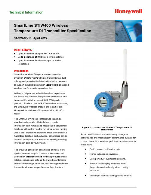
SmartLine STIW400 Wireless Temperature DI Transmitter Specification 34-SW-03-11, April 2022Model STIW400•Up to 4 channels of inputs for T/C’s or mV.•Up to 2 channels of RTD’s or 3-wire resistance.•Up to 4 channels for discrete input or 2-wireresistance.IntroductionSmartLine Wireless Temperature continues theevolution of Honeywell’s wireless transmitter productoffering and provides the latest critical advancementsto support industrial automation users’ desire to expandwireless use for monitoring and control.With over 14 years of industrial wireless experience,the SmartLine Wireless Temperature builds upon andis compatible with the current XYR 6000 productporfotlio. Similar to the XYR 6000 wireless transmitter,the SmartLine Wireless product line is part of theHoneywell OneWireless™ system and is ISA100 -ready.The SmartLine Wireless Temperature transmitterenables customers to obtain data and createinformation from remote and hazardous measurement locations without the need to run wires, where running wire is cost prohibitive and/or the measurement is in a hazardous location. Without wires, transmitters can be installed and operational in minutes, quickly providing information back to your system.The previous generation transmitters primarily were applied to monitoring applications but experienced users know that Honeywell’s wireless products are as reliable, secure, and safe as their wired counterparts. With this knowledge, users are now looking for wireless transmitters for use in specific control applications.Figure 1 — SmartLine Wireless Temperature DITransmitterSmartLine Wireless introduces a step change in performance and most notably, performance suitable for control. SmartLine Wireless performance is improved in these ways:•Fast ½ second publication rate.•Higher radio range coverage.•More powerful 4dBi integral antenna.•Smarter local display with more localdiagnostics and radio signal and qualityindicators.•More input channels and types than earlier.XYR 6000 Wireless Pressure Transmitter Differential Pressure Models 2SmartLine Wireless Temperature retains the following desirable features from the XYR 6000 product offering:•Mesh or non-mesh configuration within each transmitter.•Generic, off-the-shelf lithium ion battery.•Two “D” size batterie s for longer life.•Choice of over-the-air or local provisioning (network security join key).•Over-the-air firmware upgrade capability.•Unique, encrypted provisionng key delivered from the factory.•Remote and integral antenna options.•24 VDC power option.•Publication rates of 1, 5, 10, or 30 seconds, plus new selections of ½ seconds and 1, 15,30, 60 minutes.•Transmitter range (integral antenna) of 1150’ (350 m) under ideal conditions.The STIW400 is a high-performance Temperature transmitter featuring performance over a wide of temperature configurations and applications.The SmartLine family is also fully tested and compliant with Experion® PKS providing the highest level of compatibility assurance and integration capabilities. SmartLine easily meets the most demanding application needs for Temperature measurement applications. SmartLine Wireless FeaturesLocal and over-the-air provisioning capability:All Honeywell wireless devices feature a secure method to join the local wireless network, also known as provisioning. SmartLine Wireless transmitters feature two methods to provision a transmitter onto the network which are eitherby using a handheld device to locally communicate through the IR interface or remotely using the over-the-air function. The over-the-air function is managed by the OneWireless gateway, Wireless Device Manager (WDM). Over-the-air firmware updates:Once joined as a member of your OneWireless network, the WDM can download new transmitter firmware releases to each SmartLine Wireless transmitter over the wireless network. Locating and accessing the transmitter locally is not required thus saving time and keeping your personnel in safe environments.Mesh and non-mesh capability: All SmartLine Wireless transmitters can be configured to operate in either a mesh network or a star (non-mesh) network. The configuration is specific to each wireless transmitter and thus the network can consist of a mixture of meshing and non-meshing devices. Non-meshing is desirable for deterministic communications which is preferred for control. Transmission power setting:To comply with local and regional requirements, SmartLine Wireless transmitters are set at the factory to the maximum transmission power setting allowed for the country of use.Non-proprietary battery:Sourcing lithium thionyl chloride batteries is much simpler since SmartLine Wireless utilizes commercial off-the-shelf batteries. Please see the list of approved battery manufacturers later in this specification. Batteries are housed in an IS-approved battery compartment making battery changes safe and easy. Backward compatibility:SmartLine Wireless transmitters can join existing OneWireless networks and interoperate with existing XYR 6000 wireless transmitters or otherISA100 Wireless compliant transmitters or networks.OneWireless Network FeaturesThe core of the Honeywell wireless solution is the OneWireless Network which consists a gateway, access point(s), and field routers.The Wireless Device Manager (WDM) serves as the gateway function and in this role, manages the communication from the wireless field devices to the process control application. Typically, the WDM connects logically to the process control network (Level 2 or wireless DMZ). As the wireless network manager, the WDM provides easy access to the entire wireless network through a browser-based user interface. The Honeywell WDM can manage devices communicating over theISA100 Wireless protocol and the Wireless HART protocol.The ability to deploy redundant WDMs improves the reliability ensuring no loss of process data which is a requirement for control applications.The Field Device Access Point (FDAP) serves in two roles in the OneWireless network infrastructure, which are: 1) access point, and 2) field router. As an access point, the FDAP directly connects to the WDM via Ethernet LAN cable. More than one access point is permitted and, when more than one is present, it ensures dual path for communications into the WDM from the field devices. As a field router, the FDAP located in the field would communicate to the FDAP acting as an access point. Using the FDAP as a router is more efficient than using field devices as routers since FDAPs are line powered devices whereas field devices are typically battery powered, and the FDAP offers greater range. The meshing capability of FDAPs allows flexibility in the setup of the wireless network to fit the requirements for wireless network performance, in terms of reliable communications, performance, and future growth. The choice of non-meshing network may be desirable for reduced communication latencies with a FDAP serving as a field router.Wireless Specifications*Actual range will vary depending on antennas, cables and site topography.SpecificationsOperating Conditions1 The Ambient Limits shown are for Ordinary Non-Hazardous locations only. Refer to the Hazardous Locations Approvals section for the Ambient Limits when installed in Hazardous Locations.Remote Antenna CablesRemote Antennas8 dBi Omnidirectional Antenna14 dBi Directional AntennaPerformance SpecificationsPerformance under Rated Conditions** Field Calibration available for increased accuracy applications.** Performance specifications are based on reference conditions of 25°C (77°F), 10 to 55% RH. *** Default values; user configurable.Physical Specifications1 Add 8.0 pounds (3.6 Kg) to any model equipped with the stainless steel housing option (Model Selection Guide Table IV selection M or N).STIW400 ISA100.11a Compliant InputsAny combination of sensor type inputs is allowed. The input channels can be configured for the following input types by using the OneWireless User Interface with the corresponding device descriptor file:Selecting any RTD / 3-Wire Ohm Resistance input on Channel 1 and on Channel 3 renders Channel 2's and Channel 4’s input terminals unavailable.The transmitter measures the analog signal from temperature sensors, discrete inputs, millivolt values or ohm values and transmits a digital output signal proportional to the measured value for direct digital communications with systems.The discrete input channels support voltage-free floating contacts. Maximum ON contact resistance is 200 ohms. Minimum OFF contact resistance is 300 ohms. Discrete Input threshold values are user configurable.The Process Variable (PV) is available for monitoring and alarm purposes. The cold junction temperature is also available for monitoring. Available PV update rates are 1, 5, 10, or 30 seconds, plus new selections of ½ sec (Refer User Manual for applicable conditions) and 1, 15, 30, 60 minutes and are set using the Wireless Builder. Slower update rates extend battery life.Input Types and RangesSTIW400 TEMPERATURE TRANSMITTER CONNECTIONST/C or mV or DI or 2 Wire ResistancePV1PV2PV3PV43 Wire RTD or ResistancePV1PV33 Wire RTD or ResistancePV1PV3PV4T/C or mV or DI or 2 Wire ResistanceMounting and DimensionsReference Dimensions:Figure 2 — Examples of typical mounting positionsFigure 3 — Examples of typical mounting positionsFigure 4 – STIW400 Informational and dimensional drawingFigure 5 — Typical mounting dimensions for STIW400Figure 6 — Typical mounting dimensions for STIW400Hazardous Locations ApprovalsRefer to control drawing 50136129, in the user manual #34-SW-25-04, for intrinsically safe installation details.Transmitter Options(indicated selection code is shown)ISA100 Wireless Release Selections (A or B)OneWireless R2xx represents the previous releases whereas R3xx is the current release. A OneWireless system with R3xx firmware can host R2xx and R3xx devices. Please select the option to match the targeted OneWireless system.Remote Antenna and Cables (M or D)The user can select one of the optional remote antennas listed. The selection of the antenna option automatically includes the remote antenna adapter.To complete the option selection, one of the remote antenna cables (1, 2, or 3) must also be selected.Lightning (Surge) Diverter and Cables (1, 2, or 3)The lightning surge diverter options includes the surge diverter and cable. The diverter features Type N connections (female) on both ends. The remote antenna adapter is not included.Remote Antenna Adapter (A)This option provides an adapter to be inserted into the opening where the integral antenna normally connects. The adapter is designed to connect to a remote antenna that the user supplies. It features a female Type N connection.Destination Country (CA, EU, or US)This selection sets the transmission power at the factory to comply with the installation country location.Mounting Brackets (1, 3, 5, or 7)The angle mounting bracket is available in either zinc-plated carbon steel or 316 stainless steel and is suitable for horizontal or vertical mounting on a two-inch (50 millimeter) pipe, as well as wall mounting.An additional flat mounting bracket is also available in carbon steel and 316 stainless steel for two-inch (50 millimeter) pipe mounting.Tagging (Option 1 or 2)The choice of 1 or 2 stainless steel wired-on tags is available. Each tag can accommodate additional data of up to 4 lines of 28 characters. The number of characters includes spaces.Note that the standard nameplate on the meter body contains the serial number and body-related data.Model Selection GuideModel Selection Guides are subject to change and are inserted into the specifications as guidance only.For more informationTo learn more about SmartLine Transmitters, visit Or contact your Honeywell Account ManagerProcess Solutions Honeywell1250 W Sam Houston Pkwy S Houston, USA, TX 77042Honeywell Control Systems LtdHoneywell House, Skimped Hill Lane Bracknell, England, RG12 1EB34-SW-03-11 April 2022©2022 Honeywell International Inc.Shanghai City Centre, 100 Jungi Road Shanghai, China 20061Sales and ServiceFor application assistance, current specifications, ordering, pricing, and name of the nearest Authorized Distributor, contact one of the offices below.ASIA PACIFICHoneywell Process Solutions, Phone: + 800 12026455 or +44 (0) 1202645583 (TAC) hfs-tac-*********************AustraliaHoneywell LimitedPhone: +(61) 7-3846 1255 FAX: +(61) 7-3840 6481 Toll Free 1300-36-39-36 Toll Free Fax: 1300-36-04-70China – PRC - Shanghai Honeywell China Inc.Phone: (86-21) 5257-4568 Fax: (86-21) 6237-2826SingaporeHoneywell Pte Ltd.Phone: +(65) 6580 3278 Fax: +(65) 6445-3033South KoreaHoneywell Korea Co Ltd Phone: +(822) 799 6114 Fax: +(822) 792 9015EMEAHoneywell Process Solutions, Phone: + 800 12026455 or +44 (0) 1202645583Email: (Sales)*************************** or (TAC)*****************************AMERICASHoneywell Process Solutions, Phone: (TAC) (800) 423-9883 or (215) 641-3610(Sales) 1-800-343-0228Email: (Sales)*************************** or (TAC)*****************************。
MKH 8070 说明书
MKH 8070 Instruction manualImportant safety instructions Important safety instructions1.Read these safety instructions and the instruction manual of the product.2.Keep these safety instructions and the instruction manual of the product.Always include all instructions when passing the product on to third parties.3.Only use attachments, accessories and spare parts specified by the manu-facturer.4.Caution: The protective basket and pop shield must be completely dry whenyou mount them on the microphone. Moisture can cause malfunctions or damage to the capsule.5.Connect the microphone only to microphone inputs and supply units thatprovide 48 V phantom powering in accordance with IEC 61938.6.Do not attempt to open the product housing on your own. The warranty isvoided for products opened by the customer.7.Refer all servicing to qualified service personnel. Servicing is requiredwhen the product has been damaged in any way, liquid has been spilled or objects have fallen into the product, when the product has been exposed to rain or moisture, does not operate normally, or has been dropped.e the product only under the conditions of use listed in the specifications.9.Let the product come to ambient temperature before switching it on.10.Do not operate the product if it was damaged during transportation.11.Always run cables so that no one can trip over them.12.Keep the product and its connections away from liquids and electricallyconductive objects that are not necessary for operating the product.13.Do not use any solvents or aggressive cleaning agents to clean the product.14.Caution: Very high signal levels can damage your hearing and your loud-speakers. Reduce the volume on the connected audio devices beforeswitching on the product; this will also help prevent acoustic feedback. Intended useThe product is designed for indoor use.It is considered improper use when the product is used for any application not named in the corresponding instruction manual.Sennheiser does not accept liability for damage arising from improper use or misuse of this product and its attachments/accessories.Before putting the products into operation, please observe the respective country-specific regulations!MKH 8070Delivery includesDelivery includes•Microphone, consisting of the MKH 8070 microphone head and the MZX 8000 XLR module•MZQ 8070 microphone clamp•MZW 8070 foam windshield•Instruction manual•Frequency response sheet•Threaded transport tubeProduct overview1 Foam windshield2 Microphone head3 XLR module4 Microphone clamp (thread adaptor included for 3/8" and 5/8" threads) MKH 8070Putting the MKH 8070 into operation Putting the MKH 8070 into operation Connecting the microphoneConnection data of the MKH 8070:•48 V ± 4 V phantom powering (P48, as per IEC 61938)•XLR-3 connector, balancedTo connect the MKH 8070 to a mixing console or recording device:f Connect the socket of the microphone cable to the microphone.f Connect the connector of the microphone cable to the mixing console orrecording device.Attaching the microphonef Select the suitable mounting thread:•Without thread insert: 5/8" thread•Thread insert: 3/8" threadf Screw the microphone clamp 4 to a stand.f Place the microphone with its back end into the microphone clamp: Makesure that the lateral slots are not covered.f Orient the microphone together with the microphone clamp and fix them byscrewing the wing screw tight.MKH 8070Using optional modulesTo suppress structure-borne noise, you can use the optional shock mount.Sennheiser MZS 20-1Using the windshieldThe windshield changes the sound only slightly, but attenuates wind noise by approx. 25 dB.f Place the MZW 8070 foam windshield 1 over the microphone head 2 so thatall lateral slots are covered.Alternative windshields are available as accessories and can be found on the MKH 8070 product page at .Using optional modulesYou can retrofit and extend the microphones of the modular MKH 8000 micro-phone series by using optional modules.The MZF 8000 II filter moduleThe MZF 8000 II filter module has been specially designed for broadcast and film applications. It effectively filters out interference caused by infrasound, such a lowfrequency wind and handling noise.f If necessary, disconnect a connected XLR cable in order to not distort thecable and to avoid short-circuits.MKH 8070Transporting the microphone f Unscrew the microphone head 2 from the XLR module 3.f Screw the MZF 8000 II filter module 4 at a suitable place in the audio signalTransporting the microphonef Let the microphone dry if you used it under extreme climatic conditions.f If necessary, remove the windshield or take the microphone out of the basketwindshield.f Slide the microphone into the transport tube.MKH 8070Cleaning and maintaining the microphoneCleaning and maintaining the microphoneCAUTIONDAMAGE TO THE PRODUCT DUE TO LIQUIDS!Liquids entering the product can short-circuit the electronics or damage the mechanics. Solvents or cleansing agents can damage the surface of the prod-uct.f Keep all liquids away from the product.f Only use a soft, slightly damp cloth to clean the product. SpecificationsPick-up pattern lobarFrequency response45 Hz to 20,000 HzSensitivity-19 dBV/Pa (112 mV/Pa)Max. sound pressure level124 dB SPLEquivalent noise level8 dB(A) (DIN-IEC 651)21 dB (CCIR 268-3)Nominal impedance25 ΩMin. terminating impedance 2 kΩPhantom powering48 V ± 4 V (P48, IEC 61938)Current consumption3,3 mADiameter19 mmLengthwith MZX 8000 XLR module 432 mm 465 mWeightwith MZX 8000 XLR module 300 g 332 gOperating temperature-10 °C to +60 °CMKH 8070MKH 8070SpecificationsPolar pattern30°150°120°60°90°0510152025dB30°0°180°150°120°60°90°125 Hz 250 Hz 500 Hz 1,000 Hz2,000 Hz 4,000 Hz 8,000 Hz 16,000 HzFrequency response-10-20-30-40-50-60dB 90°0°50 H z100 H z200 H z500 H z1 k H z2 k H z5 k H z10 k H z20 k H zManufacturer declarationsManufacturer declarationsWarrantySennheiser electronic GmbH & Co. KG gives a warranty of 24 months on these products.For the current warranty conditions, please visit our website at or contact your Sennheiser partner.Warranty FOR AUSTRALIA and NEW ZEALAND ONLY:Sennheiser Australia Pty Ltd provides a warranty of 24 months on these prod-ucts.For the current warranty conditions, visit Sennheiser website:Australia: https:///New Zealand: https:///Sennheiser goods come with guarantees that cannot be excluded under Aus-tralian and New Zealand Consumer law. You are entitled to a replacement or refund for a major failure and compensation for any other reasonably fore-seeable loss or damage. You are also entitled to have the goods repaired or replaced if the goods fail to be of acceptable quality and the failure does not amount to a major failure.This warranty is in addition to other rights or remedies under law. Nothing in this warranty excludes, limits or modifies any remedy available to be consumer which is granted by law.To make a claim under this contract, raise a case via Sennheiser website Australia: https:///service-support-contactNew Zealand: https:///service-support-contactAll expenses of claiming the warranty will be borne by the person making the claim.Sennheiser international warranty is provided by: Sennheiser Australia Pty Ltd (ABN 68 165 388 312) Level 14, Tower A Zenith Building, 821 Pacific Highway, Chatswood NSW 2067, AustraliaIn compliance with the following requirementsEU: WEEE Directive (2012/19/EU)UK: WEEE Regulations (2013)Notes on disposalThe symbol of the crossed-out dumpster on the product, the (rechargeable) battery (if applicable) and/or the packaging indicates that these products must MKH 8070Manufacturer declarations not be disposed of with normal household waste, but must be disposed of sep-arately at the end of their service life. For the packaging, follow the regulations in your country for separating waste. Improper disposal of packaging materials can be harmful to your health and the environment.The separate collection of waste electrical and electronic equipment, (re-chargeable) batteries (if applicable) and packaging is intended to promote reuse and recycling and to prevent negative impacts on public health and the environment, for example due to hazardous substances contained in these products. At the end of their service life, recycle electrical and electronic equipment and (rechargeable) batteries so that their materials can be reused and to prevent environmental pollution.If (rechargeable) batteries can be removed without destroying them, you are obliged to dispose of them separately (see the product’s operating instructions for information on how to remove the batteries safely). Be especially careful when handling (rechargeable) batteries containing lithium, as these pose spe-cial hazards, such as the risk of fire and/or health risks if button cells are swal-lowed. Reduce battery waste as much as possible by using longer-life batteries or rechargeable batteries.Further information on the recycling of these products can be obtained from your municipal administration, from the municipal collection points, or from your Sennheiser partner. You may also be able to return electrical or electronic equipment to your distributor, if they are legally required to do so. By dispos-ing of your batteries properly, you are helping to protect public health and the environment.EU Declaration of conformity•RoHS Directive (2011/65/EU)•EMC Directive (2014/30/EU)UK Declaration of conformity•RoHS Regulations (2012)•EMC Regulations (2016)The full text of the EU declaration of conformity is available at the following internet address: /download.Statements regarding the FCC and Industry Canada rulesThis device complies with part 15 of the FCC rules. Operation is subject to the following two conditions: (1) this device may not cause harmful interference, and (2) this device must accept any interference received, including interfer-ence that may cause undesired operation.MKH 8070Compliance ComplianceEurope EN 55032EN 55035UKUSA FCC 47 CFR 15 subpart BCanada Industry Canada ICES_003ChinaAustralia/New ZealandMKH 8070Sennheiser electronic GmbH & Co. KGAm Labor 1, 30900 Wedemark, Germany, Printed in Germany, Publ. 07/23, 581395/A04。
海拉斯LABOFUGE400和400R一般用途离心机说明书

HERAEUS®LABOFUGE®400 AND 400 R GENERAL PURPOSE CENTRIFUGESGreat value and functionality for routine workThe Labofuge ®400tabletop centrifuge and the refrigerated version, theLabofuge ®400 R , are ideal for centri-fuging average sized samples in routine laboratory applications in the fields of research, biology and medicine.Thanks to an extensive range of rotors and accessories, these centrifuges can be used for practically everyseparation task: from highspeed cen-trifugation in microliter tubes to gentle sedimentation of animal cell cultures in conical tissue culture tubes.Of course, the right capacity is also available for your particular needs.The swinging bucket rotor can handle,for example, 36 x 7ml tubes,12 x 15ml conical tissue culture tubes or 28 x 15ml tubes for aerosol tight centrifugation.A unique feature of this series is the rotor for centrifuging microplates. The rotor is designed with a radius of 15 cm (5.9 inch) so that themicroplates can swing out vertically.The sediment is concentrated in the center of the wells for easy andaccurate photometric analysis.The Labofuge ®400 is equipped with a new air cooling system which makes it extremely quiet (less than 58 dB).The versatile swinging bucket rotor can accommodate round buckets or special cyto buckets. There aredifferent Centri-Lab ®adapters for the aerosol tight round bucket so that a variety of centrifugation tubes can be used in the swinging bucket rotor. All common types of cyto centrifugation can be carried out with the cyto bucket in combination with our extensive range of accessories.LABOFUGE ®400AccessoriesWe have developed safety carts for the Labofuge ®400and Labofuge ®400 R so that they can be used in an under-bench set-up or as mobile tabletop units.ServiceHeraeus ®centrifuges are designed for everyday use in the laboratory.The digital self-diagnosis program monitors the Labofuge ®400and the Labofuge ®400 R and immediately indicates failures on the display.The Labofuge ®400can also take a rotor which holds 2 microplates. Used together with a 24-place fixed angle rotor for 1.5/2.0ml microliter tubes, the Labofuge ®400is trans-formed into a highspeed microliter centrifuge.Adapter sets, enabling centrifugation of all commercially available microliter tubes from 0.2ml to 0.6ml, areavailable as an option. The polypropy-lene plastic rotor can be autoclaved and offers wide ranging chemical resistance.BiocontainmentAs an alternative, the rotor can be sealed with an aerosol tight screw lid for applications involving radioactive or infectious materials. A snap lid for quick closing and an aerosol tight lid are both included.The swinging buck-et rotor’s round buckets can also be sealed with aerosol tight screw caps.A 24-place haematocrit rotor for deter-mining exact haematocrit values can also be used in the Labofuge ®400.1)1)Not available for sale in the U.S.Labofuge ®400 – extremely quiet as a result of a new type of air cooling systemIn many separation tasks, it is essen-tial to maintain a constant sample temperature. The Labofuge ®400 R ensures low temperatures (0 – 4 °C)even during long runs or centrifugation at high speeds.The Labofuge ®400 R operates with the same versatile range of rotors and accessories as the Labofuge ®400,but achieves significantly higher speeds.A microprocessor controlled tempera-ture surveillance system prevents samples from freezing.For example, if samples are kept in the closed rotor chamber of the Labofuge ®400 R for an extended period of time after centrifugation,there is no danger of freezing despite standstill cooling. Of course, the Labofuge ®400 R operates with the CFC -free refrigerant, R134a.LABOFUGE ®400 RSwinging bucket rotor 75008179withround bucket 75008172(left), aerosol tight cap 75008173(middle) and cyto bucket 75008176(right)The Labofuge ®400 R ensures stablesample temperatures during centrifugationA c h t u n g : h i e r S e i t e n e n d e !!! w e g e n L o c h u n gADVANTAGESLabofuges ®400and 400 R are designed with state-of-the-art technology, providing clearadvantages for routine operations.–soft-start/soft-brake function for gentle centrifugation and tapered braking for sensitive samples.q smooth and quiet operation–rotor overspeed protection –accessories for aerosol tight centrifugationq Labofuge ®400 R operates with Not available for sale in the U.S.TECHNICAL DATACYTOACCESSORIESORDERING INFORMATIONFor easy ordering, take advantage of our low-priced “sets” (not in USA), completely equipped to handle a wide range of centrifugation applicationsType of tube: ML = microliter tube; Blood c. = Blood collection tube; US-Urine = conical urine tube; Con = conical tissue culture tube; Univ. = Universal Container;DIN = borosilicate tube with dimensions according DINAdapters can hold tubes with the following shaped bottoms: F = flat bottom; R = round bottom; C = conical bottomNot available for sale in the U.S.25,4 mm = 1 inchFor Ordering or Technical InformationRegistered to ISO 9001. Kendro Laboratory Products meet or exceed stringent quality and product safety standards. ©2003 Kendro Laboratory Products. All Rights Reserved.Specifications and dimensions are subject to change without notice.Printed in Germany 5C 09/03 4t Druckerei – xxxxxx-1。
AT8035固定电荷微电压微克罗夫斯微波筒说明书

broadcast & production microphonesA T8035Line + Gradient Condenser MicrophoneFeatures• Designed for video production and broadcast (ENG/EFP) audio acquisition• Provides the narrow acceptance angle desirable for long-distance sound pickup• Smooth, natural-sounding on-axis audio quality• Offers the convenience of battery or phantom power operation • Rugged design and construction for reliable performance• Switchable 80 Hz high-pass filter minimizes pickup of undesired low-frequency soundsDescriptionThe AT8035 is a fixed-charge condenser microphone with a line + gradient polar pattern. It is designed for video production, broadcast (ENG/EFP) audio acquisition, wildlife recording and high-quality sound reinforcement.The microphone requires 11V to 52V phantom power or a 1.5V AAbattery for operation. A battery need not be in place for phantom power operation.The microphone's highly directional polar pattern provides a narrow acceptance angle along with crisp, intelligible audio reproduction desirable for long-distance sound pickup.The output of the microphone is a 3-pin XLRM-type connector.A switch permits choice of flat response or low-frequency roll-off (via integral 80 Hz high-pass filter) to help control undesired ambient noise.The microphone is enclosed in a rugged housing. The included AT8405a stand clamp permits mounting on any microphone stand with 5/8"-27 threads. A windscreen, two o-rings, a battery and a protective carrying case are also included.Operation and MaintenanceThe AT8035 requires 11V to 52V phantom power or a 1.5V AA battery for operation. A battery need not be in place for phantom power operation.To install the battery, unscrew the lower section of the microphone body, just below the nameplate. Insert a fresh 1.5V AA battery in the handle compartment (“+” end up), then reassemble the microphone. Alkaline batteries are recommended for longest life. Remove the battery during long-term storage.Output is low impedance (Lo-Z) balanced. The signal appears across Pins 2 and 3; Pin 1 is ground (shield). Output phase is “Pin 2 hot”—positive acoustic pressure produces positive voltage at Pin 2.To avoid phase cancellation and poor sound, all mic cables must be wired consistently: Pin 1-to-Pin 1, etc.An integral 80 Hz high-pass filter provides easy switching from a flat frequency response to a low-end roll-off. The roll-off position reduces the pickup of low-frequency ambient noise (such as traffic, air-handling systems, etc.), room reverberation and mechanically coupled vibrations. To engage the high-pass filter, use the end tip of a paperclip or other small pointed instrument to slide the switch toward the “bent” line.Avoid leaving the microphone in the open sun or in areas wheretemperatures exceed 110° F (43° C) for extended periods. Extremely high humidity should also be avoided.Note: T o use the microphone with a camera-mount microphone holder whose diameter is too large to secure the microphone, slide the two supplied o-rings onto the microphone handle, spaced so that one fits just in front of, and the other fits just behind, the rubber nubs inside the microphone holder. When the top of the microphone holder is closed and tightened down, the o-rings should hold the microphone securely in place.Audio-Technica Corporation ©2016 Audio-TechnicaP51963-01AT8035LEGEND 200 Hz 1 kHz 5 kHz 8 kHzSCALE IS 5 DECIBELS PER DIVISION240˚210˚270˚300˚330˚0˚150˚120˚90˚30˚60˚12" or more on axis LEGENDFrequency in HertzR e s p o n s e i n d BRoll-off frequency response: 40–20,000 Hzpolar patternSpecificationsFixed-charge back plate, permanently polarized condenser Line + gradient 40-20,000 Hz80 Hz, 18 dB/octavePhantom: –38 dB (12.5 mV) re 1V at 1 Pa Battery: –39 dB (11.2 mV) re 1V at 1 Pa Phantom: 250 ohms Battery: 300 ohmsPhantom: 132 dB SPL, 1 kHz at 1% T.H.D. Battery: 120 dB SPL, 1 kHz at 1% T.H.D. Phantom: 110 dB, 1 kHz at Max SPL Battery: 98 dB, 1 kHz at Max SPL 72 dB, 1 kHz at 1 Pa 11-52V DC, 2 mA typical 1.5V AA/UM30.4 mA / 1200 hours typical (alkaline)Flat, roll-off 170 g (6.0 oz)369.0 mm (14.53") long,21.0 mm (0.83") diameter Integral 3-pin XLRM-type SG1AT8405a stand clamp for 5/8"-27 threaded stands; 5/8"-27 to 3/8"-16 threaded adapter; AT8132 windscreen; battery; two o-rings; protective carrying caseElementPolar pattern Frequency response Low frequency roll-off Open circuit sensitivityImpedanceMaximum input sound level Dynamic range (typical) Signal-to-noise ratio 1Phantom power requirementsBattery typeBattery current / lifeSwitch Weight Dimensions Output connectorAudio-Technica case styleAccessories furnishedIn the interest of standards development, A.T.U.S. offers full details on its test methods to other industryprofessionals on request.1 Pascal = 10 dynes/cm 2 = 10 microbars = 94 dB SPL1Typical, A-weighted, using Audio Precision System One.Specifications are subject to change without notice.To reduce the environmental impact of a multi-language printed document, product information is available online at in a selection of languages.Afin de réduire l’impact sur l’environnement de l’impression de plusieurs langues, lesinformations concernant les produits sont disponibles sur le site dans une large sélection de langue.Para reducir el impacto al medioambiente, y reducir la producción de documentos en varios leguajes, información de nuestros productos están disponibles en nuestra página del Internet: .Para reduzir o impacto ecológico de um documento impresso de várias linguas, a Audio-T echnica providência as informações dos seus produtos em diversas linguas na .Per evitare l’impatto ambientale che la stampa di questo documento determinerebbe, leinformazioni sui prodotti sono disponibili online in diverse lingue sul sito .Der Umwelt zuliebe finden Sie die Produktinformationen in deutscher Sprache und weiteren Sprachen auf unserer Homepage: .Om de gevolgen van een gedrukte meertalige handleiding op het milieu te verkleinen, is productinformatie in verschillende talen “on-line” beschikbaar op: 本公司基于减少对环境的影响,将不作多语言文檔的印刷,有关产品信息可在 的官方网页上选择所属语言和浏览。
阿尔法潜水器核心产品系列用户指南说明书
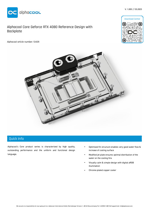
Alphacool's Core product series is characterized by high quality,outstanding performance and the uniform and functional design language.•Optimised fin structure enables very good water flow &increase of cooling surface•Modified jet plate ensures optimal distribution of the water on the cooling fins•Visually calm & simple design with digital aRGB illumination•Chrome-plated copper coolerV. 1.000 // 03.2023Alphacool Core Geforce RTX 4080 Reference Design with BackplateAlphacool article number: 13439- Nvidia Geforce RTX 4080 Reference Design- INNO3D GeForce RTX 4080 X3 OC, 16GB GDDR6X, HDMI, 3x DP- INNO3D GeForce RTX 4080 X3, 16GB GDDR6X, HDMI, 3x DP- INNO3D GeForce RTX 4080 iCHILL X3, 16GB GDDR6X, HDMI, 3x DP (C40803-166XX-187049H)- PNY GeForce RTX 4080 16GB XLR8 Gaming Verto Epic-X RGB Overclocked Triple Fan, 16GB GDDR6X, HDMI, 3x DP (VCG408016TFXXPB1-O) (*) - PNY GeForce RTX 4080 16GB XLR8 Gaming Verto Epic-X RGB Triple Fan, 16GB GDDR6X, HDMI, 3x DP (VCG408016TFXXPB1) (*)- PNY GeForce RTX 4080 16GB Verto Triple Fan, 16GB GDDR6X, HDMI, 3x DP (VCG408016TFXPB1) (*)(* The cooler is compatible with the GPU, but the rear part of the PCB is not covered. This has no negative effect on the cooling performance!)1x Core Geforce RTX 4080 Reference Design Cooler 1x Backplate4x 8x8x1mm Pad3x 40x15x1mm Pad2x 84x8x1mm Pad1x Thermal Grease1x Putty tool4x M2x5mm Screw4x EVA Washer 1x Screwdriver1x 45x45x3mm GPU-Pad 3x 56x8x3mm Pad2x 84x8x3mm Pad7x M2x10mm Screw1x PCI Bracket1x ARGB Adapter2x G1/4 Plug1x Plug toolAlphacool's Core product series is characterized by high quality, outstanding performance and the uniform and functional design language.The copper cooler which, like the end terminal, is milled from a single piece of copper and is the core of this cooler. The fine workmanship, paired with the hard and resistant chrome plating covering the entire copper cooler, meet the highest quality standards. The chrome-plated brass G1/4" threads integrated on both sides stand out visually from the terminal. They are a central feature of the new design language that will be evident in all products in the Core series.The aluminum backplate adapted to the design, together with the terminal, makes up the entire unit and enhances the back of the cooler with a clean and homogeneous look. The lighting consists of digitally addressable RGB LEDs, which illuminate the entire cooler evenly and effectively.The technical advancements can be seen in the water supply to the jet plate as well as in the optimization of the jet plate itself. The jet plate has been completely redesigned based on many simulations and practical tests in cooperation with board partners. The fin thickness and spacing have been enhanced, the cooling surface has been increased and the water flow to the core components with the greatest heat output has been optimized. The enclosed special soft thermal pads with up to 7 W/mK adapt perfectly to even the smallest tolerances.Drawing。
ANALOG DEVICES ADM803 ADM809 ADM810 数据手册

REV.CInformation furnished by Analog Devices is believed to be accurate and reliable. However, no responsibility is assumed by Analog Devices for itsuse, nor for any infringements of patents or other rights of third parties that may result from its use. No license is granted by implication or otherwise under any patent or patent rights of Analog Devices. Trademarks and registered trademarks are the property of their respective companies.One Technology Way, P.O. Box 9106, Norwood, MA 02062-9106, U.S.A. Tel: 781/329-4700 Fax: 781/326-8703© 2003 Analog Devices, Inc. All rights reserved.ADM803/ADM809/ADM810Microprocessor Supervisory Circuitsin 3-Lead SC70 and SOT-23FEATURESSpecified over TemperatureLow Power Consumption (17 A)Precision Voltage Monitor: 2.5 V, 3 V, 3.3 V, 5 V Options Reset Assertion Down to 1 V V CC140 ms Min Power-On ResetOpen-Drain RESET Output (ADM803)Push-Pull RESET Output (ADM809)Push-Pull RESET Output (ADM810)SC70 and SOT-23 PackagesAPPLICATIONSMicroprocessor SystemsComputersControllersIntelligent InstrumentsAutomotive SystemsFUNCTIONAL BLOCK DIAGRAMVVV CCFigure 1.Typical Operating CircuitGENERAL DESCRIPTIONThe ADM803/ADM809/ADM810 supervisory circuits monitor the power supply voltage in microprocessor systems. They pro-vide a reset output during power-up, power-down, and brownout conditions. On power-up, an internal timer holds reset asserted for 240 ms. This holds the microprocessor in a reset state until conditions have stabilized. The RESET output remains opera-tional with V CC as low as 1 V. The ADM803 and ADM809 provide an active low reset signal (RESET), while the ADM810 provides an active high signal (RESET) output. The ADM809 and ADM810 have push-pull outputs whereas the ADM803 has an open-drain output, which requires an external pull-up resistor. Seven reset threshold voltage options are available, suitable for monitoring a variety of supply voltages. Refer to Table I.The reset comparator features built-in glitch immunity, making it immune to fast transients on V CC.The ADM803/ADM809/ADM810 consume only 17 µA, making it suitable for low power portable equipment. The ADM803 is available in a 3-lead SC70; the ADM809/ADM810 is available in 3-lead SOT-23 and SC70 packages.查询ADM803LAKS-REEL供应商ADM803/ADM809/ADM810–SPECIFICATIONS(V CC = full operating range, T A = T MIN to T MAX,V CC Typ = 5 V for L/M/J models, 3.3 V for T/S models, 3 V for R models, 2.5 V for Z models, unless otherwise noted.)Parameter Min Typ Max Unit Test Conditions/CommentsV CC OPERATING VOLTAGE RANGE 1.0 5.5V T A = 0°C to 70°C1.2 5.5V T A = –40°C to +125°CSupply Current2435µA V CC < 5.5 V, ADM8_L/M/J,T A = –40°C to +85°C1730µA V CC < 3.6 V, ADM8_R/S/T/Z,T A = –40°C to +85°C60µA V CC < 5.5 V, ADM8_L/M/J,T A = 85°C to 125°C60µA V CC < 3.6 V, ADM8_R/S/T/Z,T A = 85°C to 125°CRESET THRESHOLDReset Voltage ThresholdADM8_L 4.56 4.63 4.70V T A = 25°CADM8_L 4.50 4.75V T A = –40°C to +85°CADM8_L 4.44 4.82V T A = –40°C to +125°CADM8_M 4.31 4.38 4.45V T A = 25°CADM8_M 4.25 4.50V T A = –40°C to +85°CADM8_M 4.20 4.56V T A = –40°C to +125°CADM8_J* 3.93 4.00 4.06V T A = 25°CADM8_J* 3.89 4.10V T A = –40°C to +85°CADM8_J* 3.80 4.20V T A = –40°C to +125°CADM8_T 3.04 3.08 3.11V T A = 25°CADM8_T 3.00 3.15V T A = –40°C to +85°CADM8_T 2.95 3.21V T A = –40°C to +125°CADM8_S 2.89 2.93 2.96V T A = 25°CADM8_S 2.85 3.00V T A = –40°C to +85°CADM8_S 2.81 3.05V T A = –40°C to +125°CADM8_R 2.59 2.63 2.66V T A = 25°CADM8_R 2.55 2.70V T A = –40°C to +85°CADM8_R 2.52 2.74V T A = –40°C to +125°CADM8_Z 2.28 2.32 2.35V T A = 25°CADM8_Z 2.25 2.38V T A = –40°C to +85°CADM8_Z 2.22 2.42V T A = –40°C to +125°CRESET THRESHOLD TEMPERATURECOEFFICIENT30ppm/°CV CC to Reset Delay20µs V CC = V TH to (V TH – 100 mV)RESET ACTIVE TIMEOUT PERIOD140240460ms T A = –40°C to +85°C100840ms T A = 85°C to 125°CRESET OUTPUT VOLTAGE LOW0.3V V CC = V TH min, I SINK = 1.2 mA, (ADM803/ADM809)ADM803R/S/T/Z, ADM809R/S/T/Z0.4V V CC = V TH min, I SINK = 3.2 mA,ADM803L/M/J, ADM809L/M/J0.3V V CC >1.0 V, I SINK = 50 µARESET OUTPUT VOLTAGE HIGH0.8 V CC V V CC > V TH max, I SOURCE = 500 µA, (ADM809)ADM809R/S/T/ZV CC – 1.5V V CC > V TH max, I SOURCE = 800 µA,ADM809L/M/JRESET OUTPUT VOLTAGE LOW(ADM810)0.3V V CC = V TH min, I SINK = 1.2 mA,ADM810R/S/T/Z0.4V V CC = V TH min, I SINK = 3.2 mA,ADM810L/M/JRESET OUTPUT VOLTAGE HIGH(ADM810)0.8 V CC V 1.8 V < V CC < V TH min,I SOURCE = 150 µARESET OPEN-DRAIN OUTPUTLeakage Current (ADM803)1µA V CC > V TH, reset de-asserted*ADM809/ADM810 only.Specifications subject to change without notice.–2–REV. CREV. C ADM803/ADM809/ADM810–3–ABSOLUTE MAXIMUM RATINGS *(T A = 25°C, unless otherwise noted.)V CC . . . . . . . . . . . . . . . . . . . . . . . . . . . . . . . . . –0.3 V to +6 V RESET, RESET . . . . . . . . . . . . . . . . . . –0.3 V to V CC + 0.5 V Input CurrentV CC . . . . . . . . . . . . . . . . . . . . . . . . . . . . . . . . . . . . . . 20 mA Output CurrentRESET, RESET . . . . . . . . . . . . . . . . . . . . . . . . . . . . 20 mA Rate of Rise, V CC . . . . . . . . . . . . . . . . . . . . . . . . . . . . 100 V/µs JA Thermal Impedance, SC70 . . . . . . . . . . . . . . . . . 146°C/W JA Thermal Impedance, SOT-23 . . . . . . . . . . . . . . . 270°C/W Lead Temperature (Soldering, 10 sec) . . . . . . . . . . . . . 300°C Vapor Phase (60 sec) . . . . . . . . . . . . . . . . . . . . . . . . . 215°C Infrared (15 sec) . . . . . . . . . . . . . . . . . . . . . . . . . . . . 220°C Storage Temperature Range . . . . . . . . . . . . –65°C to +150°C*Stresses above those listed under Absolute Maximum Ratings may cause perma-nent damage to the device. This is a stress rating only; functional operation of the device at these or any other conditions above those listed in the operational sections of this specification is not implied. Exposure to absolute maximum ratings for extended periods of time may affect device reliability.PIN CONFIGURATIONRESET, RESET V CCVt 1 = RESET TIME = 240ms TYPV REF = RESET VOL T AGE THRESHOLDFigure 2.Power Fail Reset TimingTable I.Reset Threshold OptionsRESET Model Threshold (V)ADM8_L 4.63ADM8_M 4.38ADM8_J * 4.00ADM8_T 3.08ADM8_S 2.93ADM8_R 2.63ADM8_Z2.32*ADM809/ADM810 only.PIN FUNCTION DESCRIPTIONSPin No.Mnemonic Function1GND0 V. Ground reference for all signals.2RESET (ADM803/Active Low Logic Output.ADM809)RESET remains low while V CCis below the reset threshold and remains low for 240ms (typ)after V CC rises above the reset threshold.2RESET (ADM810)Active High Logic Output.RESET remains high while V CC is below the reset threshold and remains high for 240ms (typ)after V CC rises above the reset threshold.3V CCSupply Voltage Being Moni-tored.CAUTIONESD (electrostatic discharge) sensitive device. Electrostatic charges as high as 4000V readily accumulate on the human body and test equipment and can discharge without detection. Although the ADM803/ADM809/ADM810 feature proprietary ESD protection circuitry, permanent damage may occur on devices subjected to high energy electrostatic discharges. Therefore, proper ESD precautionsare recommended to avoid performance degradation or loss of functionality.ADM803/ADM809/ADM810ORDERING GUIDE (ADM803 and ADM809)Model Reset Threshold (V)Temperature Range Branding Quantity Package Type ADM803LAKS-REEL 4.63–40°C to +125°C M0210 k3-Lead SC70 ADM803LAKS-REEL-7 4.63–40°C to +125°C M02 3 k3-Lead SC70 ADM803MAKS-REEL 4.38–40°C to +125°C M0310 k3-Lead SC70 ADM803MAKS-REEL-7 4.38–40°C to +125°C M03 3 k3-Lead SC70 ADM803TAKS-REEL 3.08–40°C to +125°C M0510 k3-Lead SC70 ADM803TAKS-REEL-7 3.08–40°C to +125°C M05 3 k3-Lead SC70 ADM803SAKS-REEL 2.93–40°C to +125°C M0610 k3-Lead SC70 ADM803SAKS-REEL-7 2.93–40°C to +125°C M06 3 k3-Lead SC70 ADM803RAKS-REEL 2.63–40°C to +125°C M0710 k3-Lead SC70 ADM803RAKS-REEL-7 2.63–40°C to +125°C M07 3 k3-Lead SC70 ADM803ZAKS-REEL 2.32–40°C to +125°C M0810 k3-Lead SC70 ADM803ZAKS-REEL-7 2.32–40°C to +125°C M08 3 k3-Lead SC70 ADM809LART-REEL 4.63–40°C to +125°C9LXX10 k3-Lead SOT-23 ADM809LART-REEL-7 4.63–40°C to +125°C9LXX 3 k3-Lead SOT-23 ADM809LAKS-REEL 4.63–40°C to +125°C M9A10 k3-Lead SC70 ADM809LAKS-REEL-7 4.63–40°C to +125°C M9A 3 k3-Lead SC70 ADM809MART-REEL 4.38–40°C to +125°C9MXX10 k3-Lead SOT-23 ADM809MART-REEL-7 4.38–40°C to +125°C9MXX 3 k3-Lead SOT-23 ADM809MAKS-REEL 4.38–40°C to +125°C M9B10 k3-Lead SC70 ADM809MAKS-REEL-7 4.38–40°C to +125°C M9B 3 k3-Lead SC70 ADM809JART-REEL 4.00–40°C to +125°C9JXX10 k3-Lead SOT-23 ADM809JART-REEL-7 4.00–40°C to +125°C9JXX 3 k3-Lead SOT-23 ADM809JAKS-REEL 4.00–40°C to +125°C M9C10 k3-Lead SC70 ADM809JAKS-REEL-7 4.00–40°C to +125°C M9C 3 k3-Lead SC70 ADM809TART-REEL 3.08–40°C to +125°C9TXX10 k3-Lead SOT-23 ADM809TART-REEL-7 3.08–40°C to +125°C9TXX 3 k3-Lead SOT-23 ADM809TAKS-REEL 3.08–40°C to +125°C M9D10 k3-Lead SC70 ADM809TAKS-REEL-7 3.08–40°C to +125°C M9D 3 k3-Lead SC70 ADM809SART-REEL 2.93–40°C to +125°C9SXX10 k3-Lead SOT-23 ADM809SART-REEL-7 2.93–40°C to +125°C9SXX 3 k3-Lead SOT-23 ADM809SAKS-REEL 2.93–40°C to +125°C M9E10 k3-Lead SC70 ADM809SAKS-REEL-7 2.93–40°C to +125°C M9E 3 k3-Lead SC70 ADM809RART-REEL 2.63–40°C to +125°C9RXX10 k3-Lead SOT-23 ADM809RART-REEL-7 2.63–40°C to +125°C9RXX 3 k3-Lead SOT-23 ADM809RAKS-REEL 2.63–40°C to +125°C M9F10 k3-Lead SC70 ADM809RAKS-REEL-7 2.63–40°C to +125°C M9F 3 k3-Lead SC70 ADM809ZART-REEL 2.32–40°C to +125°C9ZXX10 k3-Lead SOT-23 ADM809ZART-REEL-7 2.32–40°C to +125°C9ZXX 3 k3-Lead SOT-23 ADM809ZAKS-REEL 2.32–40°C to +125°C M9G10 k3-Lead SC70 ADM809ZAKS-REEL-7 2.32–40°C to +125°C M9G 3 k3-Lead SC70–4–REV. CREV. C ADM803/ADM809/ADM810–5–ORDERING GUIDE (ADM810)ModelReset Threshold (V)Temperature Range Branding Quantity Package Type ADM810LART-REEL 4.63–40°C to +125°C ALXX 10 k 3-Lead SOT-23ADM810LART-REEL-7 4.63–40°C to +125°C ALXX 3 k 3-Lead SOT-23ADM810LAKS-REEL 4.63–40°C to +125°C MAA 10 k 3-Lead SC70ADM810LAKS-REEL-7 4.63–40°C to +125°C MAA 3 k 3-Lead SC70ADM810MART-REEL 4.38–40°C to +125°C AMXX 10 k 3-Lead SOT-23ADM810MART-REEL-7 4.38–40°C to +125°C AMXX 3 k 3-Lead SOT-23ADM810MAKS-REEL 4.38–40°C to +125°C MAB 10 k 3-Lead SC70ADM810MAKS-REEL-7 4.38–40°C to +125°C MAB 3 k 3-Lead SC70ADM810JART-REEL 4.00–40°C to +125°C AJXX 10 k 3-Lead SOT-23ADM810JART-REEL-7 4.00–40°C to +125°C AJXX 3 k 3-Lead SOT-23ADM810JAKS-REEL 4.00–40°C to +125°C MAC 10 k 3-Lead SC70ADM810JAKS-REEL-7 4.00–40°C to +125°C MAC 3 k 3-Lead SC70ADM810TART-REEL 3.08–40°C to +125°C ATXX 10 k 3-Lead SOT-23ADM810TART-REEL-7 3.08–40°C to +125°C ATXX 3 k 3-Lead SOT-23ADM810TAKS-REEL 3.08–40°C to +125°C MAD 10 k 3-Lead SC70ADM810TAKS-REEL-7 3.08–40°C to +125°C MAD 3 k 3-Lead SC70ADM810SART-REEL 2.93–40°C to +125°C ASXX 10 k 3-Lead SOT-23ADM810SART-REEL-7 2.93–40°C to +125°C ASXX 3 k 3-Lead SOT-23ADM810SAKS-REEL 2.93–40°C to +125°C MAE 10 k 3-Lead SC70ADM810SAKS-REEL-7 2.93–40°C to +125°C MAE 3 k 3-Lead SC70ADM810RART-REEL 2.63–40°C to +125°C ARXX 10 k 3-Lead SOT-23ADM810RART-REEL-7 2.63–40°C to +125°C ARXX 3 k 3-Lead SOT-23ADM810RAKS-REEL 2.63–40°C to +125°C MAF 10 k 3-Lead SC70ADM810RAKS-REEL-7 2.63–40°C to +125°C MAF 3 k 3-Lead SC70ADM810ZART-REEL 2.32–40°C to +125°C AZXX 10 k 3-Lead SOT-23ADM810ZART-REEL-7 2.32–40°C to +125°C AZXX 3 k 3-Lead SOT-23ADM810ZAKS-REEL 2.32–40°C to +125°C MAG 10 k 3-Lead SC70ADM810ZAKS-REEL-72.32–40°C to +125°CMAG3 k3-Lead SC70REV. C–6–ADM803/ADM809/ADM810–Typical Performance CharacteristicsTEMPERA TURE (؇C)30252015105S U P P L Y C U R R E N T (A )TPC 1.Supply Current vs. Temperature (No Load)020406080100120140160180P O W E R -D O W N R E S E T (s )TEMPERA TURE (؇C)200TPC 2.Power-Down RESET Delay vs. Temperature ADM8_L/M/J020406080100120140160180P O W E R -D O W N R E S E T (s )TEMPERA TURE (؇C)TPC 3.Power-Down RESET Delay vs. Temperature ADM8_T/S/R/Z235.0235.5236.0236.5237.0237.5238.0238.5239.0239.5240.0P O W E R -D O W N R E S E T (s )TEMPERA TURE (؇C)–40–2002040608085TPC 4.Power-Down RESET Delay vs. Temperature ADM8_R0.99901.00201.00151.00101.00051.00000.9995NO R M A L I Z E D R E S E T T H R E S H O L DTEMPERA TURE (؇C)–40–2002040608085TPC 5.Normalized RESET Voltage Threshold vs.TemperatureTPC 6.RESET Output Voltage vs. Supply VoltageREV. C ADM803/ADM809/ADM810–7–4003500110100010030025050200150100RESET COMP ARA TOR OVERDRIVE, V TH – V CC (mV)M A X I M U M T R A N S I E N T D U R A T I O N (s )TPC 7.Maximum Transient Duration without Causing a Reset Pulse vs. Reset Comparator OverdriveINTERFACING TO OTHER DEVICES’ OUTPUTThe ADM803/ADM809/ADM810 series is designed to integrate with as many devices as possible and, therefore, has a standard output dependent on V CC . This enables the part to be used in both 3 V and 5 V or any nominal voltage within the minimum and maximum specifications for V CC . Because of this design approach, interfacing this device to other devices is simplified.Ensuring a Valid Reset Output Down to V CC = 0 VWhen V CC falls below 0.8 V, the ADM803/ADM809’s RESET no longer sinks current. A high impedance CMOS logic input connected to RESET may, therefore, drift to undetermined logic levels. To eliminate this problem, a 100k Ω resistor should be connected from RESETto ground.V Figure 3.Ensuring a Valid Reset Output Down to V CC = 0 VBenefits of a Very Accurate Reset ThresholdIn other microprocessor supervisory circuits, tolerances in supply voltages lead to an overall increase in reset tolerance levels due to the deterioration of the microprocessor reset circuit’s power supply. The possibility of a malfunction during a power failure is greatly reduced because the ADM803/ADM809/ADM810 series can operate effectively even when there are large degradations of the supply voltages. Another advantage of the ADM803/ADM809/ADM810 series is its very accurate internal voltage reference circuit. These benefits combine to produce an excep-tionally reliable voltage monitor circuit.Interfacing to Microprocessors with Multiple InterruptsIn a number of cases, it is necessary to interface many interrupts from different devices (e.g., thermal, altitude, and velocity sensors).The ADM803/ADM809/ADM810 can easily be integrated into existing interrupt-handling circuits (Figure 4) or be used as astandalone device.TOFigure 4.Interfacing to Microprocessors with Multiple InterruptsREV. C–8–ADM803/ADM809/ADM810OUTLINE DIMENSIONS3-Lead Small Outline Transistor Package [SOT-23](RT-3)Dimensions shown in millimetersCOMPLIANT TO JEDEC STANDARDS TO-236AB3-Lead Thin Shrink Small Outline Transistor Package [SC70](KS-3)Dimensions shown in millimeters0.10 COPLANARITYREV. C ADM803/ADM809/ADM810–9–Revision HistoryLocationPage6/03—Data Sheet changed from REV. B to REV. C.Added ADM803 . . . . . . . . . . . . . . . . . . . . . . . . . . . . . . . . . . . . . . . . . . . . . . . . . . . . . . . . . . . . . . . . . . . . . . . . . . . . . . . . . .Universal Changes to FEATURES . . . . . . . . . . . . . . . . . . . . . . . . . . . . . . . . . . . . . . . . . . . . . . . . . . . . . . . . . . . . . . . . . . . . . . . . . . . . . . . . . .1Changes to GENERAL DESCRIPTION . . . . . . . . . . . . . . . . . . . . . . . . . . . . . . . . . . . . . . . . . . . . . . . . . . . . . . . . . . . . . . . . . . . . .1Changes to Figure 1 . . . . . . . . . . . . . . . . . . . . . . . . . . . . . . . . . . . . . . . . . . . . . . . . . . . . . . . . . . . . . . . . . . . . . . . . . . . . . . . . . . . . . .1Changes to SPECIFICATIONS . . . . . . . . . . . . . . . . . . . . . . . . . . . . . . . . . . . . . . . . . . . . . . . . . . . . . . . . . . . . . . . . . . . . . . . . . . . .2Changes to Table I . . . . . . . . . . . . . . . . . . . . . . . . . . . . . . . . . . . . . . . . . . . . . . . . . . . . . . . . . . . . . . . . . . . . . . . . . . . . . . . . . . . . . .3Updated ORDERING GUIDE . . . . . . . . . . . . . . . . . . . . . . . . . . . . . . . . . . . . . . . . . . . . . . . . . . . . . . . . . . . . . . . . . . . . . . . . . . . . .41/03—Data Sheet changed from REV. A to REV. B.Changes to SPECIFICATIONS . . . . . . . . . . . . . . . . . . . . . . . . . . . . . . . . . . . . . . . . . . . . . . . . . . . . . . . . . . . . . . . . . . . . . . . . . . . .2Changes to Table I . . . . . . . . . . . . . . . . . . . . . . . . . . . . . . . . . . . . . . . . . . . . . . . . . . . . . . . . . . . . . . . . . . . . . . . . . . . . . . . . . . . . . .3Changes to ORDERING GUIDE . . . . . . . . . . . . . . . . . . . . . . . . . . . . . . . . . . . . . . . . . . . . . . . . . . . . . . . . . . . . . . . . . . . . . . . . . . .4Changes to TPCs 1–3, and TPC 7 . . . . . . . . . . . . . . . . . . . . . . . . . . . . . . . . . . . . . . . . . . . . . . . . . . . . . . . . . . . . . . . . . . . . . . . . . .5Updated OUTLINE DIMENSIONS . . . . . . . . . . . . . . . . . . . . . . . . . . . . . . . . . . . . . . . . . . . . . . . . . . . . . . . . . . . . . . . . . . . . . . . .710/02—Data Sheet changed from REV. 0 to REV. A.Addition of SC70 package . . . . . . . . . . . . . . . . . . . . . . . . . . . . . . . . . . . . . . . . . . . . . . . . . . . . . . . . . . . . . . . . . . . . . . . . . . .Universal Change to GENERAL DESCRIPTION . . . . . . . . . . . . . . . . . . . . . . . . . . . . . . . . . . . . . . . . . . . . . . . . . . . . . . . . . . . . . . . . . . . . . .1Changes to SPECIFICATIONS . . . . . . . . . . . . . . . . . . . . . . . . . . . . . . . . . . . . . . . . . . . . . . . . . . . . . . . . . . . . . . . . . . . . . . . . . . . .2Changes to ABSOLUTE MAXIMUM RATINGS . . . . . . . . . . . . . . . . . . . . . . . . . . . . . . . . . . . . . . . . . . . . . . . . . . . . . . . . . . . . . .3Change to Table I . . . . . . . . . . . . . . . . . . . . . . . . . . . . . . . . . . . . . . . . . . . . . . . . . . . . . . . . . . . . . . . . . . . . . . . . . . . . . . . . . . . . . . .3Change to ORDERING GUIDE . . . . . . . . . . . . . . . . . . . . . . . . . . . . . . . . . . . . . . . . . . . . . . . . . . . . . . . . . . . . . . . . . . . . . . . . . . . .4Change to TPC 1 . . . . . . . . . . . . . . . . . . . . . . . . . . . . . . . . . . . . . . . . . . . . . . . . . . . . . . . . . . . . . . . . . . . . . . . . . . . . . . . . . . . . . . .5Updated OUTLINE DIMENSIONS . . . . . . . . . . . . . . . . . . . . . . . . . . . . . . . . . . . . . . . . . . . . . . . . . . . . . . . . . . . . . . . . . . . . . . . .7–10––11–)C(3/6––6373C –12–。
迪拜科技 迪拜智能家居系统 型号:DJ-H100说明书
说明书GRUNDFOSS pumps, ranges 50-70S1, S2, S3, ST, SV7.5 - 155 kW安装和使用说明书中文 (CN)2中文 (CN) 安装和使用说明书中文版本。
目录页1. 本文献中所用符号2. 概述该手册对配备功率为7.5至160 kW电机、50-70系列的格兰富S潜水式污水及废水泵的安装、操作及保养进行了说明。
本手册还对防爆泵作了特别说明。
2.1 应用50-70系列的S泵适用于公共设施、私人住宅以及工业应用中的污水及废水泵送设计。
水泵具有多种安装方式,包括潜水式、干式、卧式以及立式安装。
最大颗粒尺寸: 80-145 mm,视具体性能范围而定。
2.1.1 潜在爆炸性环境在潜在爆炸性环境中应使用50-70机型的S防爆泵。
见章节 2.5.1防爆证书和防爆等级。
1.本文献中所用符号22.概述22.1应用22.2运行条件32.3声压级32.4型号说明42.5铭牌53.安全63.1潜水及干式立式安装的起吊点(S/C/D)64.运输与存放65.安装75.1安装类型75.2在自动耦合装置上的潜水安装85.3干式安装85.4潜水式安装,便携式95.5圆筒管内立式安装95.6泵的控制装置95.7电流分离95.8IO 11395.9热敏开关95.10湿度开关95.11热敏电阻105.12Pt100温度传感器106.WIO 传感器 (油中含水率传感器)106.1WIO 传感器为水泵配件106.2装配WIO 传感器106.3电气数据,WIO 传感器106.4传感器信号107.电气连接117.1变频器操作117.2电缆数据118.启动128.1检查旋转的方向129.保养和服务139.1检查油位并更换机油139.2检查并调整叶轮间隙149.3防爆型S 泵,50-70系列159.4受污染的泵1510.故障查找1611.回收处理16警告装机前,先仔细阅读本安装操作手册。
安装和运行必须遵守当地规章制度并符合公认的良好操作习惯。
Cessna产品型号说明书
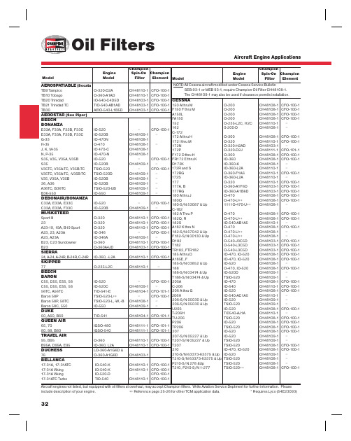
CESSNA150 A thru M O-200 CH48108-1 CFO-100-1F150 F thru M O-200 CH48108-1 CFO-100-1A150L O-200 CH48108-1 CFO-100-1FA150 O-200 CH48108-1 CFO-100-1152 O-235-L2C, H2C CH48110-1 –162 0-200-D CH48108-1 –C-172172 A thru H O-300 CH48108-1 CFO-100-1172 I thru M O-320 CH48110-1 CFO-100-1172N O-320-H2AD CH48103-1 –172P O-320-D2J CH48111-1 CFO-101-1F172 D thru H O-300 CH48108-1 CFO-100-1FR172 E thru K IO-360 CH48108-1 CFO-100-1R172K IO-360-K CH48108-1 –172R and S IO-360-L2A CH48110-1 –172RG O-360-F1A6 CH48110-1 CFO-100-1172S IO-360-L2A CH48110-1 –177 O-320 CH48110-1 CFO-100-1177A, B O-360-A1F6D CH48103-1 CFO-100-1177RG IO-360-A1B6D CH48103-1 CFO-100-1180 A thru J O-470 CH48108-1 CFO-100-1180Q O-470-U++ CH48108-1 CFO-100-1180-S/N 53087 & Up 1111O-470-U++ CH48108-1 –C-182182 A Thru P O-470 CH48108-1 CFO-100-1182Q, R O-470-U++ CH48108-1 CFO-100-1182S IO-540-AB1A5 CH48110-1 –A182 K thru N O-470 CH48108-1 CFO-100-1182-S/N 67042 & Up O-470-U++ CH48108-1 –F182-S/N 00130 & Up O-470-U++ CH48108-1 –R182 O-540-J3C5D CH48103-1 CFO-100-1T182 O-540-L3C5D CH48103-1 CFO-100-1TR182, FTR182 O-540-L3C5D CH48103-1 CFO-100-1185 A thru D IO-470, IO-520 CH48108-1 CFO-100-1A185E, F IO-470, IO-520 CH48108-1 CFO-100-1185-S/N 03852 & Up IO-520 CH48108-1 –188 O-470, IO-520 CH48108-1 CFO-100-1188-S/N 03474 & Up IO-520D CH48109-1 –T188-S/N 03474 & Up TSIO-520 CH48109-1 –205A IO-470 CH48108-1 CFO-100-1C-206 IO-540 CH48110-1 CFO-100-1206 A thru G IO-520 CH48108-1 CFO-100-1206H IO-540-AC1A5 CH48110-1 –206-S/N 05030 & Up IO-520 CH48109-1 –206-S/N 05030 & Up TSIO-520 CH48109-1 –U206 IO-520 CH48108-1 CFO-100-1T-206H TI0540-AJ1A CH48110-1 –TU-206 TSIO-520 CH48108-1 CFO-100-1P206 IO-520 CH48108-1 CFO-100-1TP206 TSIO-520 CH48108-1 CFO-100-1207 IO-520 CH48108-1 CFO-100-1207-S/N 05227 & Up IO-520 CH48109-1 –T207-S/N 05227 & Up TSIO-520 CH48109-1 –T207 TSIO-520 CH48108-1 CFO-100-1210 IO-470, IO-520 CH48108-1 CFO-100-1210-S/N 63373-63375 & Up IO-520 CH48109-1 –T210-S/N 63373-63375 & Up TSIO-520 CH48108-1 –P210-S/N 278 &Up TSIO-520 CH48108-1 –T210, P210-S/N 1-277 TSIO-520++ CH48108-1 CFO-100-1 32Aircraft engines not listed, but equipped with oil fi lters at overhaul, may accept Champion fi lters. Write Aviation Service Deptment for further information. Please include description of your engine. ++ Reference page 25-26 for other TCM application data. * Requires Lyco (54E23093) AEROSPATIABLE (SocataTB9 Tampico O-320-D2A CH48110-1 CFO-100-1TB10 Tobago O-360-A1AD CH48110-1 CFO-100-1TB20 Trinidad IO-540-C4D5D CH48103-1 CFO-100-1TB21 Trinidad TC TIO-540-AB1AD CH48103-1 CFO-100-1TB30 AEIO-540-L1B5D CH48103-1 CFO-100-1AEROSTAR (See Piper)BEECHBONANZAE33A, F33A, F33B, F33C IO-520 – CFO-100-1E33A, F33A, F33B, F33C IO-520B CH48109-1 –G-33 IO-470N CH48108-1H-35 O-470 CH48108-1 –J, K, M-35 IO 470-C CH48108-1N, P-35 IO-470-N CH48108-1S35, V35, V35A, V35B IO-520 – CFO-100-1S35 IO-520B CH48109-1 –V35TC, V35A-TC, V35B-TC TSIO-520 – CFO-100-1V35TC, V35A-TC, -V35B-TC TSIO-520D CH48109-1 –V35, V35A, V35B IO-520B CH48109-1 –36, A36 IO-520B CH48109-1 –A36TC, B36TC TSIO-520-UB CH48109-1 –B36-550 IO-550 CH48109-1 –DEBONAIR/BONANZAC33A, E33A, E33C IO-520 – CFO-100-1C33A, E33A, F33C IO-520B CH48109-1 –MUSKETEERSport III O-320 CH48110-1 CFO-100-123 O-320 CH48110-1 CFO-100-1A23-19, 19A, B19 Sport O-320 CH48110-1 CFO-100-1A23, 23, A23A IO-346 – CFO-100-1A23, A23A IO-346A CH48109-1 –B23, C23 Sundowner O-360 CH48110-1 CFO-100-1B23 O-360A4JD CH48103-1 CFO-100-1SIERRA24, A-24, A-24R, B-24R, C-24R IO-360, -L2A CH48110-1 CFO-100-1SKIPPER77 O-235-L2C CH48110-1 –BEECHBARONC55, D55, E55, 58 IO-520 – CFO-100-1C55, D55, E55, 58 IO-520C CH48109-1 –56TC, A56TC TIO-541-E CH48104-1 CFO-101-1Baron 58P TSIO-520-L++ – CFO-100-1Baron 58P, 58TC TSIO-520-L, -W, -B CH48108-1 –Baron 58C, 550 IO-550 CH48109-1 –DUKE60, A60, B60 TIO-541 CH48104-1 CFO-101-1QUEEN AIR65, 70 IGSO-480 CH48111-1 CFO-101-180, 88, B80 IGSO-540 CH48111-1 CFO-101-1TRAVEL AIR95, B95 O-360 CH48110-1 CFO-100-1B95A, D95A, E95 IO-360, L2A CH48110-1 CFO-100-1DUCHESS LO-360-A1G6D &76 O-360-A1G6D CH48103-1BELLANCA17-31A, 17-31ATC IO-540-K CH48110-1 CFO-100-117-31A Viking IO-540-K CH48110-1 CFO-100-117-31A Viking IO-520-D – CFO-100-117-31ATC Turbo TIO-540 CH48110-1 CFO-100-1ChampionEngine Spin-On ChampionModel Model Filter ElementChampionEngine Spin-On ChampionModel Model Filter ElementNOTE: A ll Cessna aircraft modifi ed under Cessna Service BulletinSEB-93-1 or MEB 93-1, require Champion Oil Filter CH48108-1.The CH48109-1 may also be used if clearance permits installation.Aircraft Engine ApplicationsCESSNA T303 LTSIO-520-AE &TSIO-520-AE CH48109-1 –310 C thru Q IO-470 CH48108-1 CFO-100-1310 RIO-520-M CH48108-1 –T310P, Q, R TSIO-520-B CH48108-1 CFO-100-1320-A TSIO-470 CH48104-1 –320-B, C TSIO-470 CH48109-1 CFO-101-1320-D TSIO-520 – CFO-100-1320-D, E, F TSIO-520-B CH48108-1 –335 TSIO-520-EB CH48109-1 –336 IO-360 CH48108-1 CFO-100-1337 IO-360 CH48108-1 CFO-100-1P337, P337H TSIO-360 CH48108-1 CFO-100-1T337H TSIO-360-H CH48108-1 CFO-100-1340 TSIO-520-K CH48108-1 –340A TSIO-520-N, -NB CH48109-1 CFO-100-1401/402TSIO-520-E CH48108-1 CFO-100-1402C TSIO-520-VB CH48109-1 CFO-100-1404GTSIO-520-M CH48111-1 CFO-101-1411-S/N 000 thru 0126 GTSIO-520-C CH48104-1 –411-S/N 0127 and up GTSIO-520-C CH48111-1 CFO-101-1414, 414A TSIO-520-J, -N CH48108-1 –421A, BGTSIO-520-D, -H, CH48111-1 CFO-101-1421C-S/N 1017 thru 1404 -L, -N, ++ CH48111-1 CFO-101-1CIRRUS AIRCRAFT SRV, SR20I0-360ES CH48108-1SR22I0-550N CH48109-1COLUMBIA/LANCAIR COLUMBIA 300, 350 I0-550N CH48109-1 CFO-100-1COLUMBIA 400 TS10-550 CH48109-1 CFO-100-1DIAMOND AIRCRAFT DA20-1C I0-240 CH48108-1 CFO-100-1DA40-180I0-360 CH48110-1 CFO-100-1GULFSTREAM AMERICAN (Single Engine Models)AA-1, 1A, 1B, 1B Trainer, TR 2/Lyco O-235 CH48110-1 CFO-100-1A1C Lynx, T-Cat Lyco O-235-L CH48110-1 CFO-100-1AA-5 Traveler Lyco O-320-E CH48110-1 CFO-100-1AA-5A Cheetah Lyco O-320-E CH48110-1 CFO-100-1AA-5B Tiger Lyco O-360-A4K CH48110-1 CFO-100-1Cougar 2/Lyco O-320-D CH48110-1 CFO-100-1COMMANDER 112, 112A IO-360-C, -L2A CH48110-1 CFO-100-1112TC TO-360-C1A6D CH48103-1 CFO-100-1114IO-540-T4A5D CH48103-1 CFO-100-1500B, 500U IO-540 CH48110-1 CFO-100-1700TIO-540-R2AD CH48103-1 CFO-100-1 33Aircraft engines not listed, but equipped with oil fi lters at overhaul, may accept Champion fi lters. Write Aviation Service Deptment for further information. Please include description of your engine. ++ Reference page 25-26 for other TCM application data. * Requires Lyco (54E23093)MAULEM5-180C, MX7-180 O-360-C, -C1F CH48110-1 M5-210C IO-360D, -L2A M5-210TCTO-360-C1A6D CH48103-1 M5-235C, M6-235, M7-235 O-540-J1A5D CH48103-1 MX-7-235O-540-W1A5D CH48103-1MOONEY AIRCRAFTM20A, B, Mark21O-360 CH48110-1M20D MasterO-360 CH48110-1 CFO-100-1 M20C RangerO-360 CH48110-1M20G StatesmanO-360CH48110-1 CFO-100-1 M20E ChaparralIO-360, -L2A CH48110-1 CFO-100-1 M20F Executive IO-360, -L2ACH48110-1 CFO-100-1 M20J-201 IO-360-A3B6D, -L2A CH48103-1 – M20K-231 TSIO-360-G, LB CH48108-1 M20M-TLS TIO-540-AFIA, B CH48110-1M20RIO-550 CH48108-1 –M22 Mustang TIO-541CH48110-1 CFO-100-1 M20K-252 TSE TSIO-360-MB1CH48108-1 –PIPER CUBPA-18 “150” O-320 CH48110-1 CFO-100-1 TRI-PACERPA-22 “150”O-320 CH48110-1 CFO-100-1 PA-22 “160”O-320CH48110-1 CFO-100-1 COMANCHEPA-24 “180” O-360CH48110-1 CFO-100-1 PA-24 “250”O-540 or IO-540 CH48110-1 CFO-100-1 PA-24B, PA-24C “260”O-540 or IO-540 CH48110-1 CFO-100-1 PA-24 Turbo “260”IO-540 CH48110-1 CFO-100-1 PAWNEEPA-25 “150” O-320 CH48110-1 CFO-100-1 A25 “260”O-540 CH48110-1 CFO-100-1 PA-36 Brave6-285B CH48109-1 –PA-36-375 Brave IO-720-D1C CH48110-1 CFO-100-1 PA-36-400 BraveIO-720D1CD CH48104-1 CFO-101-1 CHEROKEE, CADET PA-28 “140”O-320 CH48110-1 CFO-100-1 PA-28 “150”O-320 CH48110-1 CFO-100-1 PA-28 “160”, “161” O-320 CH48110-1 CFO-100-1 PA-28 “180”O-360CH48110-1 CFO-100-1 PA-28 “180”, “181”O-360-A4M CH48110-1 CFO-100-1 PA-28 “235”O-540 CH48110-1 CFO-100-1 PA-28 “151”O-320CH48110-1 CFO-100-1 ARROWPA-28R “180”IO-360, L2ACH48110-1 CFO-100-1 PA-28R “180 IO-360-C1CD, L2A CH48103-1 CFO-100-1 PA-28R “200” Arrow II IO-360, L2A CH48110-1 CFO-100-1 PA-284 “200” Turbo Arrow IIITSIO-360 CH48108-1 – PA-28-R-201TTSIO-360-F1CH48108-1Champion Engine Spin-On Champion Model ModelFilter ElementChampionEngine Spin-On Champion Model ModelFilter Element Aircraft Engine Applications34TWIN COMMANCHEPA-30 “160” Turbo IO-320 CH48110-1 CFO-100-1PA-39 “160” IO-320 CH48110-1CFO-100-1LIO-320 CH48110-1 CFO-100-1PA-39 “160” Turbo IO-320 CH48110-1 CFO-100-1LIO-320 CH48110-1 CFO-100-1NAVAJOPA-31 “300” IO-540 CH48110-1 CFO-100-1PA-31 “310” Turbo TIO-540 CH48110-1 CFO-100-1PA-31 “325” IO-540-F2BD CH48103-1 CFO-100-1LTIO-540-F2BD CH48103-1 CFO-100-1PA-31 “350” Chieftain TIO-540-J2BD CH48103-1 CFO-100-1LTIO-540-J2BD CH48103-1 CFO-100-1PA-31P “425” TIGO-541 CH48104-1 CFO-101-1PA-31P “350” Mojave TIO/LIO-540-V2AD CH48104-1SENECAPA-34 IO-360C CH48110-1 CFO-100-1LIO-360C CH48110-1 CFO-100-1PA-34 IO-360-C1E6D CH48103-1 CFO-100-1LIO-360-C1E6D CH48103-1 CFO-100-1Seneca II LTSIO-360-E CH48108-1 –TSIO-360-E CH48108-1 –Seneca III TSIO-360-KB CH48108-1PA-34-220T LTSIO-360-KB CH48108-1PIPER AEROSTARPA-60-600, -600A IO-540-G, -K CH48110-1 CFO-100-1PA-60-604, -601B IO-540-P, -S CH48110-1 CFO-100-1PA-60-601P IO-540-S CH48110-1 CFO-100-1PA-60-602P IO-540-AA1A5 CH48110-1 CFO-100-1SEMINOLEPA-44-180 O-360-E1AD CH48103-1* CFO-100-1PA-44-180T TO-360-E1A6DLTO-360-E1A6D CH48103-1* CFO-100-1 ChampionEngine Spin-On ChampionModel Model Filter ElementChampionEngine Spin-On Champion Model Model Filter ElementDAKOTAPA-28-235 O-540-J3A5D CH48103-1* CFO-100-1PA-28-201T TSIO-360-FB CH48108-1 –CHEROKEE SIXPA-32 “260” O-540 CH48110-1 CFO-100-1PA-32 “300” IO-540 CH48110-1 CFO-100-1PA-32R “300” IO-540-K1AD CH48103-1* CFO-100-1PA-32R “300” TIO-540-S1AD CH48103-1* CFO-100-1PA-32RT-300T TIO-540-S1AD CH48103-1* CFO-100-1PA-32-301 IO-540-K1G5D CH48103-1* CFO-100-1PA-32-301 TIO-540-S1AD CH48103-1* CFO-100-1PA-32R-301 IO-540-K1G5D CH48103-1* CFO-100-1PA-32R-301 TIO-540-S1AD CH48103-1* CFO-100-1TOMAHAWKTrainer PA-38-112 O-235-L2C CH48103-1* CFO-100-1MALIBUPA-46-301P Cont TSIO-520-BE CH48109-1MALIBU MIRAGEPA-46-350-P Lyco TIO-540-AE2A CH48103-1APACHEPA-23 “150” O-320 CH48110-1 CFO-100-1PA-23 “160” O-320 CH48110-1 CFO-100-1PA-23 “235” O-540 CH48110-1 CFO-100-1AZTECPA-23 “250” O-540 CH48110-1 CFO-100-1“C” PA-23 IO-540 CH48110-1 CFO-100-1PA-23 Turbo “250” IO-540 CH48110-1 CFO-100-1“C”, “D”, “E”, “F”PA-23 Turbo “250” TIO-540 CH48110-1 CFO-100-1Dimensional DataChampion Thread Dry WeightPart No. A B C D (SAE) Lbs./Kg.CH48103-1 4.48” (11.4 cm) 0.43” (1.09 cm) 1.00” Hex (2.54 cm) 3.71” (9.4 cm) 13/16-16-UNS-2B 1.32lbs. (0.59kg) CH48104-1 5.73” (14.6 cm) 0.43” (1.09 cm) 1.00” Hex (2.54 cm) 3.71” (9.4 cm) 13/16-16-UNS-2B 1.41lbs. (0.64kg) CH48108-1 4.48” (11.4 cm) 0.43” (1.09 cm) 1.00” Hex (2.54 cm) 3.71” (9.4 cm) 3/4-16-UNF-2B 1.40lbs. (0.64kg) CH48109-1 5.73” (14.6 cm) 0.43” (1.09 cm) 1.00” Hex (2.54 cm) 3.71” (9.4 cm) 3/4-16-UNF-2B 1.51lbs. (0.68kg) CH48110-1 4.48” (11.4 cm) 0.43” (1.09 cm) 1.00” Hex (2.54 cm) 3.71” (9.4 cm) 3/4-16-UNF-2A 1.38lbs. (0.63kg) CH48111-1 5.73” (14.6 cm) 0.43” (1.09 cm) 1.00” Hex (2.54 cm) 3.71” (9.4 cm) 3/4-16-UNF-2A 1.47lbs. (0.67kg)Popular spin-on oil fi ltersAircraft engines not listed, but equipped with oil fi lters at overhaul, may accept Champion fi lters. Write Aviation Service Department for furtherinformation. Please include description of your engine. * Requires Lyco (54E23093)Aircraft Engine Applications。
- 1、下载文档前请自行甄别文档内容的完整性,平台不提供额外的编辑、内容补充、找答案等附加服务。
- 2、"仅部分预览"的文档,不可在线预览部分如存在完整性等问题,可反馈申请退款(可完整预览的文档不适用该条件!)。
- 3、如文档侵犯您的权益,请联系客服反馈,我们会尽快为您处理(人工客服工作时间:9:00-18:30)。
REVERSE VOLTAGE. (V)
.8 1.0 1.2 1.4 FORWARD VOLTAGE. (V)
HE RA F8 06 G~ HE RA F8 08 G
1.6
1.8
- 293 -
.406(10.3) .390(9.90) .134(3.4)DIA .113(3.0)DIA
.272(6.9) .248(6.3)
.112(2.85) .100(2.55)
Mechanical Data
Cases: ITO-220AC molded plastic Epoxy: UL 94V-O rate flame retardant Terminals: Leads solderable per MILSTD-202, Method 208 guaranteed Polarity: As marked High temperature soldering guaranteed: 260oC/ 0.25” (6.35mm) from case for 10 seconds Mounting torque: 5 in – 1bs. Max. Weight: 2.24 grams
AVERAGE FORWARD CURRENT. (A)
20
FIG.3- TYPICAL REVERSE CHARACTERISTICS
1000
16 12 8 4 0
INSTANTANEOUS REVERSE CURRENT. ( A)
Tj=125 0C
100
10
Tj=25 0C
0
50 CASE TEMPERATURE. ( C)
Features
Low forward voltage drop High current capability High reliability High surge current capability
.185(4.7) .173(4.4) .124(3.16) .118(3.00)
ITO-220AC
50W NONINDUCTIVE 10W NONINDUCTIVE +0.5A (-) DUT (+) 50Vdc (approx) (-) PULSE GENERATOR (NOTE 2) 1W NON INDUCTIVE OSCILLOSCOPE (NOTE 1) (+) 0 -0.25A trr
FIG.5- TYPICAL JUNCTION CAPACITANCE
3.0 1.0
150
CAPACITANCE.(pF)
120 90
HE
HE
RA
0.3 0.1
F8
01
G~
HE
60 30 0
RA
RA
F8
F8
06
05
G
G~
HE
RA
0.03
F8 08 G
1
2
5
10
20
50
100
200
500
.01 .4
.6
o
100
150
PEAK FORWARD SURGE CURRENT. (A)
FIG.4- MAXIMUM NON-REPETITIVE FORWARD SURGE CURRENT
150
1
120 90 60 30
8.3ms Single Half Sine Wave JEDEC Method
0.1 0 20 40 60 80 100 120 140 PERCENT OF RATED PEAK REVERSE VOLTAGE. (%)
.063(1.6) MAX
.161(4.1) .146(3.7)
.606(15.5) .583(14.8)
.110(2.8) .098(2.5)
.071(1.8) MAX
.543(13.8) .512(13.2)
2
PIN 1 PIN 2 Case Positive
.100(2.55)
.100(2.55)
V V V A A
8.0 150 1.0 1.3 10.0 400 50 80 80 60 1.7
V uA uA nS pF ℃/W ℃ ℃
Cj
RθJC TJ
2.0 -65 to +150 Storage Temperature Range TSTG -65 to +150 Notes: 1. Reverse Recovery Test Conditions: IF=0.5A, IR=1.0A, IRR=0.25A 2. Measured at 1 MHz and Applied Reverse Voltage of 4.0V D.C. 3. Mounted on Heatsink Size of 2 in x 3 in x 0.25 in Al-Plate..
- 292 -
元器件交易网
RATINGS AND CHARACTERISTIC CURVES (HERAF801G THRU HERAF808G)
FIG.1- REVERSE RECOVERY TIME CHARACTERISTIC AND TEST CIRCUIT DIAGRAM
NOTES: 1. Rise Time=7ns max. Input Impedance= 1 megohm 22pf 2. Rise Time=10ns max. Sourse Impedance= 50 ohms
-1.0A 1cm SET TIME BASE FOR 5/ 10ns/ cm
FIG.2- MAXIMUM FORWARD CURRENT DERATING CURVE
元器件交易网
HERAF801G THRU HERAF808G
Isolation 8.0 AMPS. Glass Passivated High Efficient Rectifiers
Voltage Range 50 to 1000 Volts Current 8.0 Amperes
FIG.6- TYPICAL FORWARD CHARACTERISTICS
100
INSTANTANEOUS FORWARD CURRENT. (A)
30 10
HE RA F8 01 G~ HE RA HE F8 RA 04 F8 G 05 G
1
2
5
10
20
50
100
NUMBER OF CYCLES AT 60Hz
Dimensions in inches and (millimeters)
Maximum Rating and Electrical Characteristics
Rating at 25℃ambient temperature unless otherwise specified. Single phase, half wave 60 Hz, resistive or inductive load. For capacitive load, derate current by 20% Symbol HERAF HERAF HERAF Type Number
Maximum Recurrent Peak Reverse Voltage Maximum RMS Voltage Maximum DC Blocking Voltage Maximum Average Forward Rectified Current .375”(9.5mm) Lead Length @TC =100℃ Peak Forward Surge Current, 8.3 ms Single Half Sine-wave Superimposed on Rated Load (JEDEC method ) Maximum Instantaneous Forward Voltage @8.0A Maximum DC Reverse Current @ TA=25℃ at Rated DC Blocking Voltage @ TA=125℃ Maximum Reverse Recovery Time (Note 1) Typical Junction Capacitance Operating Temperature Range ( Note 2 ) Typical Thermal Resistance (Note 3)
HERAF HERAF HERAF HERAF HERAF
801G 802G 803G 804G 805G 806G 807G 808G
Units
VRRM VRMS VDC I(AV) IFSM VF IR Trr
50 35 50
100 200 300 400 600 800 1000 70 140 210 280 420 560 700 100 200 300 400 600 800 1000