ERZA80JK112中文资料
MRA112-A中文资料

Distinctive CharacteristicsActual SizeLow profile body of MRF model accommodates space limitations required for PCB mounting. For the MRA and MRK bushing mount models, the range of behind panel body depths is .323” to .669” (8.2mm to 17.0mm).Positive detent mechanism for distinct feel and audible feedback. Metal bushing and housing construction increases durability. Adjustable stopper plate allows 2–12 position settings. High contact reliability achieved by the self-cleaning contact mechanism.Break-before-make contact timing with sliding contacts in MRA and rotary contactor disk in MRF and MRK models. Interior housing seal and molded-in PC terminals, plus shaft rubber o-ring on MRF and MRK and polyamide cover on MRF model, allow cleaning after automated soldering.Exterior rubber washer and double flatted bushing on MRA and MRKgive protection in splashproof applications.General SpecificationsElectrical Capacity (Resistive Load)For MRA:250mA @ 125V ACFor MRF or MRK:0.4VA maximum @ 28V AC/DC maximum(Applicable Range 0.1mA ~ 0.1A @ 20mV ~ 28V)Note: Find additional explanation of operating range in Supplement section.Other RatingsContact Resistance:10 milliohms maximum for MRA; 50 milliohms maximum for MRF & MRKInsulation Resistance: 100 megohms minimum @ 500V DCDielectric Strength: 1,000V AC minimum for 1 minute minimum for MRA500V AC minimum for 1 minute minimum for MRF & MRKMechanical Life: 30,000 operations minimumElectrical Life: 10,000 operations minimumRange of Operating Torque:0.02 ~ 0.07Nm for MRA; 0.005 ~ 0.02Nm for MRF & MRKContact Timing: Nonshorting (break-before-make)MRA – self-cleaning, sliding contact; MRF & MRK – self-cleaning, rotary contactor disk Indexing: 30°Materials & FinishesShaft: Brass with nickel platingStopper Plate: Steel with zinc plating for MRA & MRK; polyamide cover with stopper for MRF Bushing/Housing: Zinc alloy with zinc platingMovable Contacts: Copper with silver plating for MRA; phosphor bronze with gold plating for MRF & MRK End Contacts & Terminals:Brass with silver plating for MRA; phosphor bronze with gold plating for MRF & MRK Common Contacts & Terminals: Brass with silver plating for MRA; phosphor bronze with gold plating for MRF & MRKBase: Diallyl phthalate for MRA; fiberglass reinforced polyamide for MRF & MRKEnvironmental DataOperating Temperature Range: –10°C through +70°C (+14°F through +158°F)Humidity: 90 ~ 95% humidity for 96 hours @ 40°C (104°F)Vibration: 10 ~ 55Hz with peak-to-peak amplitude of 1.5mm traversing the frequency range& returning in 1 minute; 3 right angled directions for 2 hoursShock: 50G (490m/s2) acceleration (tested in 3 right angled directions, with 3 shocks in each direction)InstallationMounting Torque: .686Nm (6.08 lb•in)Cap Installation Force:19.6 ~ 29.4N (4.41 ~ 6.61 lbf) for MRA & MRKProcessingSoldering Time & Temperature: Wave Soldering for MRA: See Profile A in Supplement section.Wave Soldering for MRF & MRK: See Profile B in Supplement section.Manual Soldering for MRA: See Profile A in Supplement section.Manual Soldering for MRF & MRK: See Profile B in Supplement section.Cleaning: Automated cleaning recommended. Stopper plate, as well as washers for MRA & MRK, must be inplace to maintain automated cleaning. See Cleaning specifications in Supplement section.Standards & CertificationsUL Recognition MRA, MRF, & MRK models have not been tested for UL recognition or CSA certification.or CSA Certification:These switches are designed for use in a low-voltage, low-current, logic-level circuit.When used as intended in a logic-level circuit, the results do not produce hazardous energy.TYPICAL SWITCH ORDERING EXAMPLEDESCRIPTION FOR TYPICAL ORDERING EXAMPLEMRA206-ANo Code BlackFor Color TippedA BlackB White CRed E Yellow F Green G Blue HGrayAShaft Actuated with PC TerminalsACTUATORS & TERMINALSShaft T erminalShaft Actuated with Plain Black Knob DP with 2-6Adjustable PositionsPC TerminalsFLow ProfileScrewdriver Actuated with PC TerminalsKLow Profile Shaft Actuated with PC TerminalsSlotted for Terminal ScrewdriverShaft Terminal.124Thk = (0.25) .010Thk = (0.25) .010Thk = (0.25) .010POSITION SETTING FOR MRA, MRF, & MRK MODELSEach switch is supplied with the stopper set for the maximum number of positions allowed for that model. Prior to installation, the desired position setting should be made. Contact factory for continuous rotation.MRF Models1. Remove the protective cover from the switch body.2. Turn the shaft counterclockwise to the extreme left by using a screwdriver.3. Inside the cover is a magnifying lens which would be positioned over the number which is to be the maximum position used; when the cover is then snapped into the switch, the projection beside the lens fits into the correct hole for setting the stop.MRK & MRA Models1. Using the actuator knob, turn the shaft counterclockwise to the extreme left. If the shaft is not turned counterclockwise to the extreme left, proper setting can- not be achieved. At this extreme posi- tion, the white line on the knob points to the number 1 position shown on the side of the switch.2. Remove the knob from the shaft and loosen the nut far enough to allow rais- ing the stopper plate, plus washer(s), for resetting to the desired position.3. Note the position numbers on the side of the switch; these correspond to the terminal numbers and stopper holes. Insert the stopper in the hole numbered for the maximum desired number of stop settings. Satisfactory switch func- tioning cannot be assured if the stopper plate is not properly positioned.4. Tighten the nut (beveled side up) firmly against the stopper plate.Standard Mounting Hardware Packaged Loose with Each Switch:TYPICAL SWITCH DIMENSIONSSingle Pole MRA112MRA • PC Terminals1 Pole2 Pole4 PoleMRF • PC Terminals1 Pole2 Pole 4 PoleMRA112MRK112MRK devices are designed to be panel mounted. Installation without panel mounting will affect reliability.MRK • PC Terminals1 Pole2 Pole 4 PoleMRF403FOOTPRINTSDouble Pole MRA206Four Pole MRA403Single Pole MRF112MRK112Double Pole MRF206MRK206Four Pole MRF403MRK403.124KNOBSAAT433Plain BlackColor Codes:BlackWhiteRedYellowGreenBlueABCEFGGrayHBase Material: Polyester Base Color:BlackPolyamide Tip Colors:A, B, C, E, F , G, HMaterial:Polyacetal Color: Black onlyBase Material:Polyester Base Color: BlackPolyamide Tip Colors:A, B, C, E, F , G, HBAT4103 Small Color TippedCAT4104 Large Color TippedPANEL CUTOUTS & MAXIMUM EFFECTIVE PANEL THICKNESSWithoutKeywaySTANDARD MOUNTING HARDWAREAT513MMetric Hexagon Nut Material:Brass, nickel plating 1 for MRA; 1 for MRKAT507MMetric Locking RingMaterial:Steel, chromate over zinc plating 1 for MRA; 1 for MRKAT509 LockwasherMaterial:Steel, chromate over zinc plating 1 for MRA; 1 for MRKAT535Rubber RingMaterial:Nitrile butadiene rubber1 for MRKNonsealed PanelSealed PanelWith Standard Hardware on Nonsealed Panel:MRA .067” (1.7mm) MRK .087” (2.2mm)Without Locking Ring on Nonsealed Panel:MRA .098” (2.5mm) MRK .118” (3.0mm)With Standard Hardware on Sealed Panel:MRK .106” (2.7mm)With Keyway.250.250.087OPTIONAL SUPPORT BRACKETAT543Support Bracket for MRK Material:Steel with tin platingA support bracket is needed when the MRK is mounted only to a PC boardand does not have the bushing through a panel..150。
红色电器红色电缆特建胶结设备说明书

RED-D-ARC PM 255Red-D-Arc Spec-Built Welding EquipmentThis RED-D-ARC welder is built to RED-D-ARC Extreme Duty design specifications by Lincoln Electric.Safety Depends on YouThis welder is designed and built with safety in mind.However, your overall safety can be increased by proper installation ... and thoughtful operation on your part.DO NOT INSTALL, OPERATE OR REPAIR THIS EQUIPMENT WITHOUT READING THIS MANUAL AND THE SAFETY PRECAUTIONS CONTAINED THROUGHOUT.And, most importantly, think before you act and be careful.OPERATOR’S MANUALIM676MARCH, 2001Mar ‘95for selecting a QUALITY product. We want you to take pride in operating this product ••• as much pride as we have in bringing this product to you!Read this Operators Manual completely before attempting to use this equipment. Save this manual and keep it handy for quick reference. Pay particular attention to the safety instructions we have provided for your protection.The level of seriousness to be applied to each is explained below:vvvi vivii viiTECHNICAL SPECIFICATIONS – PM 255Read entire installation section before starting installation.SAFETY PRECAUTIONSUNCRATING THE PM 255Cut banding and lift off cardboard carton. Cut banding holding the machine to the skid. Remove foam and corrugated packing material. Untape accessories from Gas Bottle Platform. Unscrew the two wood screws (at the Gas Bottle Platform) holding the machine to the skid. Roll the machine off the skid assembly.LOCATIONLocate the welder in a dry location where there is free circulation of clean air into the louvers in the back and out the front. A location that minimizes the amount of smoke and dirt drawn into the rear louvers reduces the chance of dirt accumulation that can block air pas-sages and cause overheating.FIGURE A.1 — Dual Voltage Machine Input Connections3. The 230/460/575 volt 60 Hz model is not equippedwith an input cable or a plug.ing the instructions in Figure A.3, have a quali-fied electrician connect the receptacle or cable tothe input power lines and the system ground perthe U.S. National Electrical Code and any applica-ble local codes. See “Technical Specifications” atthe beginning of this chapter for proper wire sizes.For long runs over 100 feet, larger copper wiresshould be used. Fuse the two hot lines with superlag type fuses as shown in the following diagram.The center contact in the receptacle is for thegrounding connection. A green wire in the inputcable connects this contact to the frame of thewelder. This ensures proper grounding of thewelder frame when the welder plug is inserted intothe receptacle.FIGURE A.2 — Triple Voltage Machine Input Connections4.Attach the rectangular 10-pin plug connector on thetimer kit wiring harness to the mating receptacle connector located directly behind the removed cover panel. Be sure that the latch on the connec-tor is aligned with the one on the board and insert it until the latch engages.5.Align the timer panel for installation and carefullyinsert the printed circuit board and wiring harness through the opening. Make sure the wiring harness is not pinched between panels or between printed circuit board and front panel cover.6.Secure the timer assembly with either the two sup-plied screws or with the original screws. The instal-lation is now complete. Refer to the following sec-tion for operating instructions.OPERATING INSTRUCTIONS FORTIMER KITIf the optional Timer Kit (K1701-1) is installed, select the desired mode with the selector switch:A.Normal Welding mode provides weld power onlywhile the trigger switch is depressed. This is the same operation as when the Timer Kit is not installed.B.4-Step Trigger interlock mode eliminates the needto hold the gun trigger while welding. It operates in4 steps:1.Close trigger and establish welding arc.2.Release trigger and continue welding.3.Reclose trigger near end of weld.4.Release trigger again to stop welding.If the arc is broken while using this feature, the machine will reset to the “trigger off” condition auto-matically.C.Spot Weld Mode is is used for tack welding partsinto position or for spot plug welds to hold thin sheet metal together prior to manual stitch or con-tinuous welding. To use this feature, adjust the On-Time (0-5 seconds) as appropriate to obtain the desired results. Closing the trigger initiates a single timed spot weld cycle. Plug welds are made by using a punch to make a 3/16" (5 mm) diameter hole in the top sheet and arc welding through the hole into the back sheet.To make spot plug welds, punch 3/16" (5 mm) holes in the top sheet. Set the Spot Time control to approximately 1.2 seconds and set the procedure for the metal thickness to be welded. Install spot weld nozzle (if available) on gun and press it against the top sheet so the top and bottom sheets are tight together. Close trigger and hold it closed until the arc goes out. If a spot weld nozzle is not used, smoother welds will result by moving the welding wire in a small circle during the weld.D.Burnback Time control provides manual adjust-ment of the burnback time (0-250 milliseconds) for any selected welding mode. this control should be set as low as possible without the wire “sticking” in the puddle after each weld. Too long of a burnback time may form a “ball” on the end of the wire, or may“flash back” to the gun tip.E.Run-In Mode is used to adjust the starting wirefeed speed. Starting conditions for certain welding applications can be improved with adjustment to the Run-In speed. The control allows for initial starting speeds from 50 - 150 IPM. After the arc is started, the set point on the wire feed speed control will dominate. Note that the Run-in is not functional with the spool gun. Also note that if Run-in is set fully counter clockwise to “OFF”, Run-in speed will equal the preset WFS on the machine.Table D.2 in this section.•Be sure the nozzle insulator is fully screwed onto the gun tube and does not block the gasholes in the diffuser.•Slip the appropriate gas nozzle onto the nozzle insulator. Either a standard .50" (12.7 mm) oroptional .62" (15.9 mm) I.D. slip-on gas nozzlemay be used and should be selected based onthe welding application.Adjust the gas nozzle as appropriate for theGMAW process to be used. Typically, the con-tact tip end should be flush to .12" (3.2 mm)extended for the short-circuiting transferprocess and .12" (3.2 mm) recessed for spraytransfer.GUN TUBES AND NOZZLES1.Replace worn contact tips as required.2.Remove spatter from inside of gas nozzle and fromtip after each 10 minutes of arc time or as required. GUN CABLE CLEANINGTo help prevent feeding problems, clean cable liner after using approximately 300 pounds (136 kg) of electrode. Remove the cable from the wire feeder and lay it out straight on the floor. Remove the contact tip from the gun. Using an air hose and only partial pres-sure, gently blow out the cable liner from the gas dif-fuser end.Excessive pressure at the start may cause the dirt to form a plug.Flex the cable over its entire length and again blow out the cable. Repeat this procedure until no further dirt comes out. If this has been done and feed prob-lems are experienced, try liner replacement, and referto trouble shooting section on rough wire feeding.*Included with PM 255ΔRequires S19418-1 Gas Diffuser Assembly.This Troubleshooting Guide is provided to help you locate and repair possible machine malfunctions.Simply follow the three-step procedure listed below.Step 1.LOCATE PROBLEM (SYMPTOM).Look under the column labeled “PROBLEM (SYMP-TOMS)”. This column describes possible symptoms that the machine may exhibit. Find the listing that best describes the symptom that the machine is exhibiting.Step 2.POSSIBLE CAUSE.The second column labeled “POSSIBLE CAUSE ” lists the obvious external possibilities that may contribute to the machine symptom.Step 3.RECOMMENDED COURSE OF ACTIONThis column provides a course of action for the Possible Cause, generally it states to contact your local Authorized Field Service Facility.If you do not understand or are unable to perform the Recommended Course of Action safely, contact your local Authorized Field Service Facility.HOW TO USE TROUBLESHOOTING GUIDEService and Repair should only be performed by Factory Trained Personnel. Unauthorized repairs performed on this equipment may result in danger to the technician and machine operator and willinvalidate your factory warranty. For your safety and to avoid Electrical Shock, please observe all safety notes and precautions detailed throughout this manual.__________________________________________________________________________Now Available...12th EditionThe Procedure Handbook of Arc WeldingWith over 500,000 copies of previous editions published since 1933, the Procedure Handbook is considered by many to be the “Bible ” of the arc welding industry.This printing will go fast so don ’t delay. Place your order now using the coupon below.The hardbound book contains over 750 pages of welding information, techniques and procedures. Much of this material has never been included in any other book.A must for all welders, supervisors, engineers and designers. Many welding instructors will want to use the book as a reference for all students by taking advantage of the low quantity discount prices which include shipping by 4th class parcel post.$15.00postage paid U.S.A. MainlandHow To Read Shop DrawingsThe book contains the latest information and application data on the American Welding Society Standard Welding Symbols. Detailed discussion tells how engineers and draftsmen use the “short-cut ” language of symbols to pass on assembly and welding information to shop personnel.Practical exercises and examples develop the reader ’s ability to visualize mechanically drawn objects as they will appear in their assembled form.187 pages with more than 100 illustrations. Size 8-1/2” x 11”Durable, cloth-covered board binding.$4.50postage paid U.S.A. MainlandNew Lessons in Arc WeldingLessons, simply written, cover manipulatory techniques;machine and electrode characteristics; related subjects,such as distortion; and supplemental information on arc welding applications, speeds and costs. Practice materials,exercises, questions and answers are suggested for each lesson.528 pages, well illustrated, 6” x 9” size, bound in simulated,gold embossed leather.$5.00postage paid U.S.A. MainlandNeed Welding Training?The Lincoln Electric Company operates the oldest and most respected Arc Welding School in the United States at its corporate headquarters in Cleveland, Ohio. Over 100,000stu-dents have graduated. Tuition is low and the training is “hands on ”For details write:Lincoln Welding School 22801 St. Clair Ave.Cleveland, Ohio 44117-1199.and ask for bulletin ED-80 or call 216-383-2259 and ask for the Welding School Registrar.Lincoln Welding SchoolBASIC COURSE $700.005 weeks of fundamentalsThere is a 10%discount on all orders of $50.00 or more for shipment at one time to one location.Orders of $50 or less before discount or orders outside of North America must be prepaid with charge, check or money order in U.S. Funds Only.Prices include shipment by 4th Class Book Rate for U.S.A. Mainland Only.Please allow up to 4 weeks for delivery.UPS Shipping for North America Only.All prepaid orders that request UPS shipment please add:$5.00For order value up to $49.99$10.00For order value between $50.00 & $99.99$15.00For order value between $100.00 & $149.00For North America invoiced orders over $50.00 & credit card orders, if UPS is requested, it will be invoiced or charged to you at cost.Outside U.S.A. Mainland order must be prepaid in U.S. Funds. Please add $2.00 per book for surface mail or $15.00 per book for air parcel post shipment.METHOD OF PAYMENT:(Sorry, No C.O.D. Orders)CHECK ONE:Name:_______________________________________________Please Invoice (only if order is over $50.00)Address:______________________________________________________________________________________________Credit Card - Telephone:_______________________________________________Signature as it appears on Charge Card:Account No.Exp Date|_|_||_|_|______________________Month YearUSE THIS FORM TO ORDER:Order from:BOOK DIVISION, The Lincoln Electric Company, 22801 St. Clair Avenue, Cleveland, Ohio 44117-1199BOOKS OR FREE INFORMATIVE CATALOGS Telephone: 216-383-2211 or, for fastest service, FAX this completed form to: 216-361-5901.Lincoln Welding School Titles:Price Code QuantityCost(ED-80)New Lessons in Arc Welding $5.00L Seminar Information Procedure Handbook “Twelfth Edition ”$15.00PH (ED-45)How to Read Shop Drawings $4.50H Educational Video Information Incentive Management $5.00IM (ED-93) A New Approach to Industrial Economics $5.00NA James F. Lincoln Arc Welding The American Century of John C. Lincoln $5.00AC Foundation Book Information Welding Preheat Calculator $3.00WC-8(JFLF-515)JapaneseChineseKoreanArabicREAD AND UNDERSTAND THE MANUFACTURER’S INSTRUCTION FOR THIS EQUIPMENT AND THE CONSUMABLES TO BE USED AND FOLLOW YOUR EMPLOYER’S SAFETY PRACTICES.SE RECOMIENDA LEER Y ENTENDER LAS INSTRUCCIONES DEL FABRICANTE PARA EL USO DE ESTE EQUIPO Y LOS CONSUMIBLES QUE VA A UTILIZAR, SIGA LAS MEDIDAS DE SEGURIDAD DE SU SUPERVISOR.LISEZ ET COMPRENEZ LES INSTRUCTIONS DU FABRICANT EN CE QUI REGARDE CET EQUIPMENT ET LES PRODUITS A ETRE EMPLOYES ET SUIVEZ LES PROCEDURES DE SECURITE DE VOTRE EMPLOYEUR.LESEN SIE UND BEFOLGEN SIE DIE BETRIEBSANLEITUNG DER ANLAGE UND DEN ELEKTRODENEINSATZ DES HER-STELLERS. DIE UNFALLVERHÜTUNGSVORSCHRIFTEN DES ARBEITGEBERS SIND EBENFALLS ZU BEACHTEN.JapaneseChineseKoreanArabicLEIA E COMPREENDA AS INSTRUÇÕES DO FABRICANTE PARA ESTE EQUIPAMENTO E AS PARTES DE USO, E SIGA AS PRÁTICAS DE SEGURANÇA DO EMPREGADOR.。
SAE J1128 2000 (中文版) 低压初级电缆

电源管理芯片DK112中文资料

电源管理芯⽚DK112中⽂资料功能描述DK112芯⽚是专⽤⼩功率开关电源控制芯⽚,⼴泛⽤于电源适配器、LED电源、电磁炉、空调、DVD等⼩家电产品。
⼀、产品特点采⽤双芯⽚设计,⾼压开关管采⽤双极型晶体管设计,以降低产品成本;控制电路采⽤⼤规模MOS数字电路设计,并采⽤E极驱动⽅式驱动双极型晶体芯⽚,以提⾼⾼压开关管的安全耐压值。
内建⾃供电电路,不需要外部给芯⽚提供电源,有效的降低外部元件的数量及成本。
芯⽚内集成了⾼压恒流启动电路,⽆需外部加启动电阻。
内置过流保护电路,防过载保护电路,输出短路保护电路,温度保护电路及光藕失效保护电路。
内置斜坡补偿电路,保证在低电压及⼤功率输出时的电路稳定。
内置PWM振荡电路,并设有抖频功能,保证了良好的EMC特性。
内置变频功能,待机时⾃动降低⼯作频率,在满⾜欧洲绿⾊能源标准(<0.3W)同时,降低了输出电压的纹波。
内置⾼压保护,当输⼊母线电压⾼于保护电压时,芯⽚将⾃动关闭并进⾏延时重启。
内建斜坡电流驱动电路,降低了芯⽚的功耗并提⾼了电路的效率。
4KV防静电ESD测试。
⼆、功率范围输⼊电压(85~264V ac)(85~145V ac)(180~264V ac)最⼤输出功率12W18W18W三、封装与引脚定义引脚符号功能描述1Gnd接地引脚。
2Gnd接地引脚。
3Fb反馈控制端。
4Vcc供电引脚。
5678Collector输出引脚,连接芯⽚内⾼压开关管Collector端,与开关变压器相连。
四、内部电路框图五、极限参数供电电压Vcc...........................................-0.3V--9V供电电流Vcc...........................................100mA引脚电压...........................................-0.3V--Vcc+0.3V 开关管耐压...........................................-0.3V--780V 峰值电流...........................................800mA总耗散功率...........................................1000mW⼯作温度...........................................0℃--125℃储存温度...........................................-55℃--+150℃焊接温度...........................................+280℃/5S六、电⽓参数项⽬测试条件最⼩典型最⼤单位电源电压Vcc AC输⼊85V-----265V456V启动电压AC输⼊85V-----265V 4.85 5.2V关闭电压AC输⼊85V-----265V 3.64 4.2V电源电流Vcc=5V,Fb=2.2V203040mA 启动时间AC输⼊85V------500mS Collector保护电压L=1.2mH460480500V开关管耐压Ioc=1mA700------V开关管电流Vcc=5V,Fb=1.6V----3.6V600650700mA 峰值电流保护Vcc=5V,Fb=1.6V----3.6V650720800mA 振荡频率Vcc=5V,Fb=1.6V----2.8V606570KHz 变频频率Vcc=4.6V,Fb=2.8V----3.6V0.5--65KHz 抖频步进频率Vcc=4.6V,Fb=1.6V----2.8V0.81 1.2KHz 温度保护Vcc=4.6V,Fb=1.6V----3.6V120125130℃占空⽐Vcc=4.6V,Fb=1.6V----3.6V5---50%控制电压Fb AC输⼊85V-----265V 1.6--- 3.6V七、⼯作原理上电启动:当外部电源上电时,直流⾼压经开关变压器传⾄芯⽚的COLLECTOR端(5678引脚),后经内建⾼压恒流启动电路将启动电流送⾄开关管Q1的B极,通过开关管Q1的电流放⼤(约为20倍放⼤)进⼊电源管理电路经D1为Vcc外部电容C1充电,同时为Fb预提供⼀个3.6V电压(Fb引脚对地应接⼊⼀只滤波电容),当Vcc的电压逐步上升⾄5V时,振荡器起振,电路开始⼯作,控制器为Fb开启⼀个约为25uA的对地电流源,电路进⼊正常⼯作。
ASTME112中文修订版

金属平均晶粒度测定方法引言本标准规定了金属材料平均晶粒度的基本方法。
由于纯粹以晶粒几何图形为基础,与金属和合金本身无关。
因此,这些基本方法也可以用来测量非金属材料中晶粒、晶体和晶胞的平均尺寸。
如果材料的组织形貌非常接近某一个标准系列评级图,可以使用比较法。
测定平均晶粒度常用比较法,也可以用截点法和面积法。
但是,比较法不能用来测量单个晶粒。
1范围1.1 本标准规定了金属组织的平均晶粒度表示及评定的三种方法——比较法、面积法和截点法。
这些方法也适用于晶粒组织形貌与标准系列评级图相似的非金属材料。
这些方法主要适用于单相晶粒组织,但也适用于多相或多组元试样中特定类型组织的晶粒平均尺寸的测量。
1.2 本标准使用晶粒面积、晶粒直径、截线长度的单峰分布来测定式样的平均晶粒度。
这些分布近似正态分布。
本标准的测定方法不适用于双峰分布的晶粒度。
双峰分布的晶粒度参见标准E1181。
测定分布在细小晶粒基体上个别非常粗大的晶粒的方法参见E 930。
1.3本标准的测量方法仅适用平面晶粒度的测量,也就是试样截面显示出的二维晶度;不适用于试样三维晶粒,即立体晶粒尺寸的测量。
1.4 试验可采用与一系列标准晶粒度图谱进行对比的方法或者在简单模板上进行计数的方法。
利用半自动计数仪或自动图象分析仪测定晶粒尺寸的方法参见E 1382。
1.5本标准仅作为推荐性试验方法,它不能确定受检材料是否接收或适合使用的范围。
1.6 测量数值应用SI单位表示。
等同的英寸-英镑数值,如需标出,应在括号中列出近似值.1.7 本标准没有列出所有的安全事项,只是一些使用的注意事项。
本标准的使用者在使用前应掌握较合适的安全健康的操作规范和使用时限制的规章制度。
1.8 章节的顺序如下:2、参考文献2.1ASTM标准E3 金相试样的制备E7 金相学相关术语E407 金属和合金浅腐蚀的操作E562计数法计算体积分数的方法E691 通过多个实验室比较决定测试方法的精确度的方法E883 反射光显微照相指南E930 截面上最大晶粒的评估方法(ALA晶粒尺寸)E1181双峰分布的晶粒度测试方法E1382 半自动或全自动图像分析平均晶粒度方法2.2 ASTM附件2.2.1 参见附录X23术语3.1 定义-本标准采用的专业术语定义参照E73.2 本标准中特定术语的定义:3.2.1 ASTM晶粒度——G,通常定义如公式(1)N AE=2G-1 (1)N AE为100倍下每平方英寸(645.16mm2)面积内包含的晶粒个数,相当于1倍下每平方毫米面积内包含的晶粒个数乘以15.5倍。
惠威LR280S线阵列音箱说明书

2
101dB (1w/1m) 130dB (连续) 136dB (峰值) 4Ω 2x15" (75mm音圈) 2xspeakon NL4 田字架吊装、落地脚垫 792x490x690mm 57kg
五、产品中有害物质的名称及含量:
此图示含义为:该产品可能含有某些有害物质(如下表所示)。在环保使用期限内可以 放心使用,超过环保使用期限之后则应该进入回收循环系统。此标识指环保使用期 限为十年(从生产日期算起)。
1. 吊挂(用专用田字架,配套LR280全频箱做扩声)。
2. 堆叠(配套LR280全频箱做扩声)。
1
三、尺寸标注图:
四、技术参数:
音箱型号 频率范围
额定输入功率
灵敏度 最大声压级 额定阻抗 低音单元 输入连接 安装 尺 寸(宽x高x深) 净重
LR280S 40Hz~350Hz 700W (连续) 1400W (节目信号) 2 8 0 0 W (峰 值)
部件名称
电缆 金属部件 木质部件 塑胶部件 电路板组件
变压器 喇叭件 包装材料
铅( P b )
X O X O X O O O
汞( H g )
O O X O O O O O
有害物质Βιβλιοθήκη 六价铬 镉( C d )(Cr(VI))
O
O
O
O
X
X
O
O
O
O
O
O
O
O
O
O
多溴联苯 (PBB) O O X O O O O O
产品说明书
一、产品特点: LR280S是HiVi惠威音响全新推出的线阵列次低音音箱系统,以解决声音远距离传输而造
成的声压级衰减。低频效果得到更好的提升。 本套系统特别适合各种篮球馆、大会堂、礼堂、剧院、演艺厅、多功能会议室等。并
弯头技术手册
Sch 用 S 表示,其后接表号数值,如 Sch10s 的代号为 S10s;Sch40 的代号为 S40。 LG、SGP、STD、XS、XXS 的代号不变,仍用原来的写法为代号。 压力等级 2000、3000、6000、和 9000 的,分别用代号 2M、3M、6M 和 9M 表示。 PN 用 P 表示,其后接公称压力数值,单位为 Mpa,如 PN2.5 的代号为 P2.5。
-1-
代号说明
为了方便设计和采购,推荐对标准管件采用如下代号:
1.联接型式的代号
连接型式
代号
连接型式
代号
对焊
B
承插焊
S
连接型式 螺纹
代号
T
2.管件种类
品种 45°弯头
90°弯头
180°弯头 三通 四通
45°Y 型三通 翻边短节
类别
长半径 等径 异径 长半径 短半径 等径 异径 长半径 短半径 等径 异径 等径 异径 等径 异径
代号
RC RE C FCS FCR HC FC HC U SHP HHP RHP HHB FB OL —
3.公称通径的代号
公称通径可直接用数值表示,外径分为两个系列的在公称通径代号后接该系列代号,如代号 100A 指公称通径 100、外径为 A 系列;50Ⅱ指公称通径 50、外径为系列Ⅱ;40GZ 指公称通径 40、外 径为公制系列;3/4 指公称通径或接管外径为 3/4 英寸。
对焊等径三通、四通尺寸 GB12459
Back to Faces
180°弯头
Elbows
P
K
DN
A 系列 B 系列 长半径 长半径 短半径 长半径 短半径 长半径 短半径
JK7122S多路耐压绝缘测试仪使用说明书

使用说明书JK7122S多路耐压绝缘测试仪ear2.0地址:江苏省常州市天宁区青洋北路1号新动力创业中心22栋C3电话:*************89187775 Tel**************89187775 传真:*************Fal**************主页地址: Http:电子邮件:****************Email:****************第一章 安全规则说明书内容若有改变,恕不另行通知。
说明书若有不详尽之处,请直接与本公司联系。
高电压测试前应该注意的规定和事项!!!1.1一般规定·使用本测试仪以前,请认真阅读说明书,了解操作规程和相关的安全标志,以保证安全。
·在开启本机的输入电源开关前,请先选择正确的输入电压(110V 或220V )规格。
危险标志,表示有高压输出,请避免接触。
机箱接地符号。
警告应注意所执行的操作、应用或条件均具有很高的危险性,可能导致人员受伤或死亡。
仪器所产生的电压电流足以造成人员伤害,为了防止意外伤害或死亡的发生,在移动和使用仪器时,请务必先观察清楚,然后再进行操作。
1. 2维护和保养1.2.1使用者的维护为了防止触电,非专业人员不要打开仪器的盖子。
本仪器内部所有的零件,不得私自更换。
如果仪器有异常情况发生,请寻求本公司指定经销商帮助。
1.2.2定期维护本系列测试仪、输入电源线、测试线和相关附件等每年至少要仔细检验和校验一次,以保证操作员的安全和仪器的精确性。
1.2.3使用者的修改使用者不得自行更改仪器的线路或零件,否则本公司的保证失效,并对由此产生的后果不负任何责任。
1. 3测试环境1.3.1工作位置操作本仪器时必须保证仪器放置于一般人员不能随意接触的地方。
如果因为生产线的安排而无法做到时,必须将测试地区与其它设施隔离并特别标明“高压测试工作区”。
如果高压测试区与其它工作区非常接近时,必须特别注意安全。
- 1、下载文档前请自行甄别文档内容的完整性,平台不提供额外的编辑、内容补充、找答案等附加服务。
- 2、"仅部分预览"的文档,不可在线预览部分如存在完整性等问题,可反馈申请退款(可完整预览的文档不适用该条件!)。
- 3、如文档侵犯您的权益,请联系客服反馈,我们会尽快为您处理(人工客服工作时间:9:00-18:30)。
Medium Size Power Transformers
Series:
J Series:J-U Series:K
V Denki Yohin stands for the safety regulations under The Electrical Appliance and Material Control Law.
q q s Features
(Series J)
q q (Series J-U)
q current product
q (Series K)
q E 1
T
2
P 3
4
5
6
7
8
9
10
Product Code
Size
Safety Std.
Type
Design No.
11
12
Option
Thickness
Style
Japan Singapore Brazil Indonesia
s Terminal Construction (K series)
Series J (J-U)
Series K
s Recommended Applications
q s Explanation of Part Numbers
Power transformer designed for PWB loading (K & J Low leakage flux utilizing new ÓUIÓ core Ð40 % less vs Improved insulation High impact strength
Pin terminal type self-supporting structure Kerosene fan heater, Refrigerator, Microwave oven, Air conditioner, Air purifier
HDTV, VCR, Karaoke set, CD radio cassette player, MD player, DVD player, Component Stereo Receiver series)
New power transformer structure using new shape ÓUIÓ core (J-U series)
Smaller and lighter due to low loss regulation Ð30 % less Appli cable Safety Standards: Denki Yohin , UL, CSA, IEC, SAA
Rev.02/04
(Vertical type)
(Horizontal type)
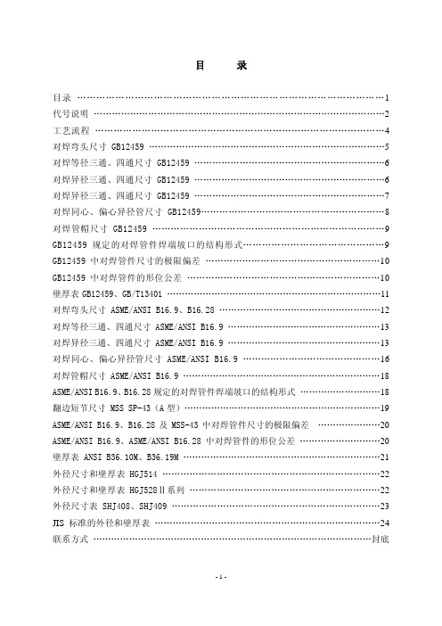
q Vertical type
Type No. of Pin Sec.Pri.A ±2.0B ±1.0 C max.D ±1.0L ±1.0S ±2.0d E ±1.0J4812A 51.043.039.514.551.062.0 3.5´4.59.568J4819A 51.043.046.021.051.062.0 3.5´4.516.068J4823A 51.043.050.025.051.062.0 3.5´4.520.066J4825A 51.043.052.027.051.062.0 3.5´4.522.068J5420A 57.547.550.022.059.068.5 4.5´6.518.068J5425A 57.547.555.027.059.068.5 4.5´6.523.069J5730A 60.5
50.0
63.0
32.5
61.0
75.0
4.5´6.5
27.0
6
8
q Horizontal type
Type No. of Pin Sec.Pri.A ±2.0B ±1.0 C max.D ±1.0L ±1.0S ±2.0d E ±1.0J4812B 42.550.039.514.559.070.0 3.5´4.59.568J4819B 42.550.046.021.059.070.0 3.5´4.516.068J4823B 42.550.050.025.059.070.0 3.5´4.520.066J4825B 42.550.052.027.059.070.0 3.5´4.522.068J5420B 48.056.550.022.066.578.0 4.5´6.518.068J5425B 48.056.555.027.066.578.0 4.5´6.523.068J5730B
50.5
59.5
63.0
32.5
71.0
82.0
4.5´6.5
27.0
6
8
q Horizontal type
Type No. of Pin Sec.Pri.A ±2.0B ±1.0 C max.D ±1.0L ±1.0S ±2.0d E ±1.0J5020A 53.0
45.0
47.0
22.0
53.0
64.0
3.5´
4.0
16.0
6
8
s Dimensions in mm (not to scale): J-U series
q Vertical type
Type No. of Pin Sec.Pri.A ±2.0B ±1.0 C max.D ±1.0L ±1.0S ±2.0d E ±1.0J5020B
45.0
52.0
49.0
22.0
61.0
72.0
3.5´
4.0
16.0
6
8
Recommended PWB Piercing Plan (tolerance±0.2mm)
K281228.530.326.020.545fig. 1K281528.530.329.023.5K351037.030.530.522.5K351537.030.535.527.53
4
fig. 2
K351837.030.538.530.5K411043.035.033.025.5K411243.035.035.528.0K411543.035.038.030.5K411743.035.040.533.0K412143.035.044.036.5K412543.035.048.040.5K413343.035.056.048.54
5
fig. 3
K431045.037.033.025.5K431245.037.035.528.0K431545.037.038.030.5K431745.037.040.533.0K432145.037.044.036.5K432545.037.048.040.5K4333
45.0
37.0
56.0
48.5
Primary 7.5mm Secondary 5.0mm
Pin Pitch
Mounting Holes Sec.Pri.
No. of Pin
Type A ±1.0B ±1.0C ±1.0D ±1.0。