低压计量箱三相电能表快装节能插拔座
三相电子式多功能电能表使用说明书

DTSD1277型DSSD1277-B型三相电子式多功能电能表使用说明书安装、使用产品前请阅读使用说明书石家庄科林自动化有限公司目录1概述 ....................................................................................................................................错误!未定义书签。
2工作原理 ............................................................................................................................错误!未定义书签。
3技术参数 ............................................................................................................................错误!未定义书签。
3.1主要型号 ...............................................................................................................................错误!未定义书签。
3.2主要技术参数 .......................................................................................................................错误!未定义书签。
3.3抄表及全失压电池 ...............................................................................................................错误!未定义书签。
电能计量箱_改1

实装电表 型号规格 1块 DGL-2 2块 DGL-2 3块 DGL-4 4块 DGL-4 5块 DGL-6 6块 DGL-6 7块 DGL-9 8块 DGL-9 9块 DGL-9 10块 DGL-12 11块 DGL-12 12块 DGL-12 13块 DGL-15 14块 DGL-15 15块 DGL-15 16块 DGL-18 17块 DGL-18 18块 DGL-18
名称
三相冷轧板壁挂式经互感器1户电能计量箱 三相冷轧板壁挂式经互感器2户电能计量箱 三相冷轧板壁挂式经互感器3户电能计量箱 三相冷轧板壁挂式经互感器4户电能计量箱
名称
三相冷轧板壁挂式1户电能计量箱 三相冷轧板壁挂式2户电能计量箱 三相冷轧板壁挂式3户电能计量箱 三相冷轧板壁挂式4户电能计量箱
实装电表 型号规格 1块 SZX-1H 2块 SZX-2H 3块 SZX-3H 4块 SZX-4H
实装电表 1块 2块 3块 4块 5块 6块 7块 8块 9块 10块 11块 12块 13块 14块 15块 16块 17块 18块
单相非金属壁挂式电能计量箱 DFX-□
型号规格 DFX-2 DFX-2 DFX-4 DFX-4 DFX-6 DFX-6 DFX-9 DFX-9 DFX-9 DFX-12 DFX-12 DFX-12 DFX-15 DFX-15 DFX-15 DFX-18 DFX-18 DFX-18
实装电表 1块 2块 3块 4块
三相不锈钢壁挂式电能计量箱 SGX-□
型号规格 SGX-1 SGX-2 SGX-3 SGX-4
三相不锈钢壁挂式经互感器电能计量箱 SGX-□H
名称
三相不锈钢壁挂式经互感器1户电能计量箱 三相不锈钢壁挂式经互感器2户电能计量箱 三相不锈钢壁挂式经互感器3户电能计量箱 三相不锈钢壁挂式经互感器4户电能计量箱
安徽省电力公司三相电能计量箱专用技术规范书修订稿

三相电能计量箱专用技术规范书1 范围本规范规定了400V电能计量箱旳专用技术规定,可作为新建、改建、扩建电力工程中400V电能计量箱旳招投标技术文献,也可作为400V电能计量箱设计、审查、验收旳根据。
2 引用原则计量箱应符合但不限于下列现行有效版本旳规范和原则:GB 4208-2023 外壳防护等级GB/T 4728 电气简图用图形符号GB 7251.1-2023 低压成套开关设备和控制设备第一部分:型式试验和部分型式试验成套设备GB 7251.3-2023 低压成套开关设备和控制设备第三部分:对非专业人员可进入现场旳低压成套开关设备和控制设备—配电板旳特殊规定GB/T 7267-2023 电力系统二次回路控制、计量屏及柜基本尺寸系列GB 10963.1-2023 家用及类似场所用过电流保护断路器第1部分:用于交流旳断路器GB/T 14048.1-2023 低压开关设备和控制设备第1部分:总则GB/T 14048.2-2023 低压开关设备和控制设备低压断路器GB/T 14048.3-2023 低压开关设备和控制设备第3部分:开关、隔离器、隔离开关及熔断器组合电器GB/T 16936-1997 电能计量柜GB 50171-1992 电气装置安装工程盘、柜及二次回路结线施工及验收规范GB 50217-2023 电力工程电缆设计规范GB 50058-1992 爆炸和火灾危险环境电力装置设计规范DL/T 448-2023 电能计量装置技术管理规程DL/T 621-1997 交流电气装置旳接地DL/T 698.1 电能信息采集与管理系统总则DL/T 698.31 电能信息采集与管理系统电能采集终端通用规定DL/T 698.33 电能信息采集与管理系统专变采集终端特殊规定DL/T 698.34 电能信息采集与管理系统公变采集终端特殊规定DL/T 698.35 电能信息采集与管理系统低压集抄终端特殊规定DL/T 825-2023 电能计量装置安装接线规则DL/T 866-2023 电流互感器和电压互感器选择及计算导则JB/T 5777.2-2023 电力系统二次回路控制及计量屏(柜、台)通用技术条件JGJ 16-2023 民用建筑电气设计规范Q/GDW347-2023 电能计量装置通用设计规范GB/T 2423.1 电工电子产品基本环境试验规程国家电网企业输变电工程通用设计 400V电能计量装置分册 (中国电力出版社出版、发行 2023年12月第一版)3 专用规定3.1 直接接入式电能计量箱3.1.1 箱体外观及构造规定1)采用悬挂式、嵌入式或落地式安装方式。
南方电网公司低压用电客户费控电能计量装置典型设计

用于采集多个客户电能表电能量信息,并经处理后通过信道将数据传送 到系统上一级(中继器或集中器)的设备。 3.3 集中抄表集中器
收集各采集终端的数据,并进行处理储存,同时能和主站进行数据交换 的设备。
3.1 电能计量装置....................................................... 2 3.2 集中抄表数据采集终端............................................... 2 3.3 集中抄表集中器..................................................... 2 3.4 计量表箱........................................................... 2 3.5 试验接线盒......................................................... 2 4 设置原则 .............................................................. 2 5 技术要求 .............................................................. 3 5.1 电能表配置技术要求................................................. 3 5.2 电流互感器技术要求................................................. 3 5.3 计量表箱技术要求................................................... 3 5.4 开关要求........................................................... 5 5.5 电能表接插件要求................................................... 5 5.6 试验接线盒技术要求................................................. 6 5.7 二次回路技术要求................................................... 6 6 布置方式和安装接线要求 ................................................ 6
电表箱结构示意图
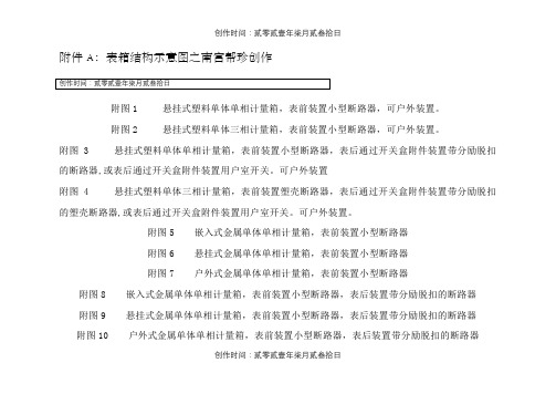
附件A:表箱结构示意图之南宫帮珍创作附图1 悬挂式塑料单体单相计量箱,表前装置小型断路器,可户外装置。
附图2 悬挂式塑料单体三相计量箱,表前装置小型断路器,可户外装置。
附图 3 悬挂式塑料单体单相计量箱,表前装置小型断路器,表后通过开关盒附件装置带分励脱扣的断路器,或表后通过开关盒附件装置用户室开关。
可户外装置附图 4 悬挂式塑料单体三相计量箱,表前装置塑壳断路器,表后通过开关盒附件装置带分励脱扣的塑壳断路器,或表后通过开关盒附件装置用户室开关。
可户外装置。
附图5 嵌入式金属单体单相计量箱,表前装置小型断路器附图6 悬挂式金属单体单相计量箱,表前装置小型断路器附图7 户外式金属单体单相计量箱,表前装置小型断路器附图8 嵌入式金属单体单相计量箱,表前装置小型断路器,表后装置带分励脱扣的断路器附图9 悬挂式金属单体单相计量箱,表前装置小型断路器,表后装置带分励脱扣的断路器附图10 户外式金属单体单相计量箱,表前装置小型断路器,表后装置带分励脱扣的断路器创作时间:贰零贰壹年柒月贰叁拾日附图11 嵌入式金属单体单相计量箱,表前装置小型断路器,表后装置带分励脱扣的断路器。
带用户室。
附图12 悬挂式金属单体单相计量箱,表前装置小型断路器,表后装置带分励脱扣的断路器。
带用户室。
附图13 户外式金属单体单相计量箱,表前装置小型断路器,表后装置带分励脱扣的断路器。
带用户室。
附图14 嵌入式金属单体单相计量箱,表前装置小型断路器。
带用户室。
附图15 悬挂式金属单体单相计量箱,表前装置小型断路器。
带用户室。
附图16 户外式金属单体单相计量箱,表前装置小型断路器。
带用户室。
附图17 嵌入式金属单体三相计量箱,表前装置小型断路器附图18 悬挂式金属单体三相计量箱,表前装置小型断路器附图19 户外式金属单体三相计量箱,表前装置小型断路器附图20 嵌入式金属单体三相计量箱,表前装置小型断路器,表后装置带分励脱扣的断路器附图21 悬挂式金属单体三相计量箱,表前装置小型断路器,表后装置带分励脱扣的断路器创作时间:贰零贰壹年柒月贰叁拾日附图22 户外式金属单体三相计量箱,表前装置小型断路器,表后装置带分励脱扣的断路器附图23 嵌入式金属单体三相计量箱,表前装置小型断路器,表后装置带分励脱扣的断路器。
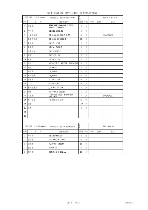
2X500KVA箱变元件材料明细表
40*4 带传感器 红1,绿1,黄1 AC220V 红1 绿1 6A
660V 0.2级 10/0.1KV
6 4 4
10 电压互感器 11 电流互感器 12 13 微断 14 熔管 15 箱体
LZZBJ9-10 0.2S/10P 30/5
DZ47-60D/2P XRNP-10 0.5A
In=10A
4 6 2
数量 单位 单价 2 2 2 6 12 台 只 只 只 只 台
金额
备注
温度控制器 排风扇 行程开关 箱式变电站
ZBW12-2*500KVA
1
高压电缆分支箱1进4出 (厦门安瑞吉电气)
1台。
第4页
共4页
2012-5-22
JZC1-44 AC220V DZ47-60/2 In=10A
三相四线多功能表 3*1.5(6)A 3*220V/380V
供电局购买
多功能表计支架
项目名称∶上林苑2*500KVA
名称及型号:低压配电柜-电容柜
数量:
编号:D12 D22
序号 1 2 3 4 5 刀开关 断路器 接触器 避雷器 电容器
名
数量:
编号:
序号 1 2 3 4 5 6 7 8 9 10 11 12 13 14 15 16 17 18 19 20 21 22 23 24 变压器 断路器
名
称
规格及型号 S11-M-500KVA DZ47-60/2P AB-WK-H(TH) AC220V 10/0.4KV 10A AC220V 基座式
数量 单位 单价 4 4 12 4 12 4 12 4 6 4 60 4 台 台 只 只 只 只 只 只 个 个 节 台
金额
备注
HXE310三相电能表安装手册说明书

Installation Manual Three Phase Energy Meter For HXE310 CT & CTPT MeterHexing Electrical Co., Ltd.[2013.3]IntroductionRange of validityThe present installation manual applies to the meter specified on the title page.PurposeThe installation manual contains all the information required for application of the meters forinstallation and maintenance.Target groupThe contents of this installation manual are intended for qualified personnel of energy supplycompanies responsible for installation and maintenance of the meter.Hexing Electrical reserves the right of final interpretationTABLE OF CONTENTSIntroduction (2)1 General view (4)2 Installation (5)2.1 Installation Requirements (5)2.2 Installation Sequence (5)2.3 Clear alarms (6)3 Maintenance (6)3.1 Replace battery (6)4 Mechanical Structure (7)4.1 Case (7)4.2 Connections (8)5 Connection Diagram (9)6 Dimension (10)7 LCD Display (11)8 Nameplate (14)9 Technical specification (16)1 General viewFigure 1.1 View of HXE310 Smart Meter (for reference)Front ViewThe meter information is printed on front cover and front door. The information could beprinted according to requirements of Power Supply Company. There is a button for dataquery and manual disconnector control, an optical communication interface for HHUoperation and local maintenance.Field of applicationThe meter is for LV or HV three-phase user. The rated voltage is 3*57.7~3×230V and themaximum current can be 10A.Characteristicsz Liquid crystal display(LCD)z Protection class IIz IP 54z Optical communicationz RS-485 communicationz Pluggable remote communication modulez With 5A disconnectorz With battery, supporting power off displayz The meter has security display modez With relay output to control2Installation2.1Installation RequirementsThe requirements for the installation site are as following:1) The site conditions should be within the protection class (IP54) of the meter.2) The temperature of air and contact surface is in the operating temperature range℃(-30℃~+70).3) There must be no harmful and corrosive air.4) The electricity network is 3*57.7~3×230V 50/60Hz The maximum current is 10A.5) The limit of the electricity network phase voltage is 276V.6) The ambient magnetic field strength is lower than 0.5mT.2.2Installation Sequence1)Check the meter for any visible damage caused by shipping. If there is visible damage,please change the meter.2)Switch off the voltage.3)Remove the terminal block cover.4)Fix the meter through suspension hanger and other installation points.(See chapter 6.Installation dimension)5)Make the required wiring carefully according to the connection diagram, which islocated on the terminal block cover.6)Strip the wires so that the stripped part of the wire is long enough to reach under bothconnector screws. Make sure the wire insulation ends before the terminal. The insulation,however, must reach the inside of the terminal block, so that it can not be touched.7)Screw all connections tight, but be careful not to break the screws. Recommended torqueis 3 Nm for size M6.8)Make relevant connections.Relay 20 21RS-485 17(A) 18(B)Pulse 13 15Check whether the connection is correct according to chapter 5 connection diagram.9)Switch on the voltage.10)Test whether RS-485 connectors are connected correctly.11)Test whether relay connectors are connected correctly.12)Switch off the voltage.13)Attach the terminal block cover and seal it.14)Switch on the voltage.15)Check whether there is S7 indicator on LCD( If there is S7, the meter cover open isdetected or there is strong magnetic field. Please check the status of meter cover andmagnetic field).16)Clear alarms by Hand Held Unit(HHU).17)Record the serial number on the nameplate for backing up the user and installationposition.2.3Clear alarmsIt is aim to clear the meter cover open alarms during the installation process. The method isas following:1)Connect the HHU and the meter through the optical probe2)Execute an alarm clearance command using HHU.3)Check whether the meter cover open alarm is cleared successfully.( The Alarm indicatoris on when there is meter cover open alarm. The Alarm indicator is off or flashes if thealarm is cleared successfully. For details, see Chapter 8 nameplate and LED indicator)4)If the meter cover open alarm is not cleared successfully, then check whether theterminal block cover is attached correctly. Repeat step 2 and 3.3Maintenance3.1Replace batteryIn the lifespan of the battery, some reasons may result in little part of batteries are run outahead of time and damage, such as the meter are stored in warehouse for a too long time, orthe temperature of the application site is too high. When the battery needs to be replaced, theindicator will flash on the LCD. The message will be sent to the master station through alarmregister. The battery could work for another week from the alarm is given to it is totally runout of use. Steps to replace battery are as following:1)Remove the seal on the front cover.2)Open the front cover.3)Replace the battery with a new one.4)Press the display button, and switch to the battery voltage interface. The circumstance isnormal if the current battery voltage is in 3.4V~3.7V. Otherwise, there is problem withthe new battery.5)Close the front cover.6)Use HHU to execute the command of setting battery remaining capacity, and make themeter to recalculate current remaining capacity of the battery as 99% remaining capacity.7)Set meter time using HHU.8)Execute the clear alarm command using HHU. The alarms for low battery and metercover open will disappear.( See 2.5 clear alarm)9)Seal the front cover again.NOTE The safety of operation people could not be guaranteed if liquid enters the meter during battery replacement process. The operation people could execute switching off the voltagebefore step (3) and switching on the voltage after step (3). It is not suitable to replace batteryin rainy time.4Mechanical Structure4.1CaseThe internal construction of the meter is not described here, as meter protected bymanufacturer seal. The meter couldn’t be opened after delivery. The front door is onlysecured by a plastic seal and can be opened to operate the button, to change the battery.The following drawing shows the meter components visible from outside.Fig 4.1.1 Front view of HXE3101 Suspension hanger2 Lower part of case3 Display button4 Upper part of case5 Optical interface6 Screw with manufacture seal7 Terminal cover8 Liquid crystal display (LCD)9 Front cover10 Company sealThe front door must be opened to access to the battery compartment and front door opendetection button.Fig 3.1.2 Meter with front cover open1.Front cover2.Button detecting front door open3.Battery compartment4.2ConnectionsThe terminal block with the meter connections is situated under the terminal cover. Twocompany seals in the fixing screw of the terminal cover prevent unauthorized access to thephase connections and therefore to unrecorded current consumption.Fig.4.2.1 Meter with terminal cover removed 5Connection DiagramFig 5.1 CT connectionFig 5.2 CT/PT connection 6DimensionFig 6.1 Meter dimensions z Width------------------------175 mmz Height -----------------------277 mmz Depth ------------------------86 mmTerminal cover-------------------35 mm free space7LCD DisplayMeter has a LCD display with following size and layout:Fig 7.1.1 Size and layout of LCDFig 7.1.2 Size of each digitFig 7.1.3 Diagram of view anglez Meter has a clear visibility with a range of view angle of δ <= 45ºright down the LCD within one meter.z Backlight display, when backlight is opened, it will have a better visibility.OBIS:z When the meter displays import active energy, the current display will be 1.8.0 . Letters are right aligned.Current tariff No.z If Tariff 1 is the current tariff, the display will be T1.Communication indicatorz If the meter is using optical communication or RS-485 communication, thecommunication indicator will flash with a frequency of 1Hz.Voltage indicatorz indicating the working status of phase voltage, and it is corresponding toA, B,C. If voltage is normal, it will be full display; if voltage is abnaomal like over-voltage,low-voltage, it will be flashing display; and if the voltage is lower than 20% of rated voltage, it willbe no display.Power direction indicatorz The arrow is right when the meter imports energy from power network. The arrow is left when the meter exports energy to power network. If there is no current, the indicator will not beshowed. (if the voltage is lower than 20% of rated voltage, it will be no display. )Battery conditionz The indicator will flash with 1Hz frequency when the voltage of battery is low or battery life is almost over. The flash will disappear after the battery is replaced.GPRS signal indicatorz The indicator shows the GPRS signal degree. (The current meter doesn’t use this indicator) Value fieldzz Up to 8-digit indices are displayed.Disconnector statusz The indicator shows the current physical status of disconnector.Unit fieldz Different units can be shown: kWh, Hz, etc.Quadrant indicatorz indicating current total working quadrant of three phase(to indicate total working status of the current working quadrants, judging from the algebraic sum of the active and reactive powerand status)Other indicatorsS1 S2 S3 S4 S5 S6 S7 S8 S9z S1: Flashing indicates the cover open event(if in the factory mode, it indicates battery cover open)z S2: The meter is in button display mode or called ALT display modez S3: The meter is in the TEST display mode.( if in the factory mode, it indicates meter cover open)z S4: The carrier is successfully registered.( if in the factory mode, it indicates terminal cover open)z S5: The auxiliary relay is disconnected now(if has this function)z S6: The disconnector could be connected by pressing button manually.z S7: Meter cover is open now; reverse phase occurs or there is magnetic field which is over0.5mT. it is used for inspections of installationz S8: EOI indicating outputz S9: The meter is in DST8NameplateFig 8.1 CT meterFig 8.2 CTPT meterMeter Installation Manual-HXE310 16 / 189Technical specificationVoltageNominal voltage Un 3x57.7V/230V Extended operating voltage range 80%~120% Un Start operating voltage 40V Limiting voltage 70V FrequencyNominal frequency fn 50Hz tolerance 45 to 55 Hz CurrentBasic current (Ib) 5A Maximum current (Imax) 6A starting current (Ist) 5mA Measurement AccuracyActive energy Class 0.5S Reactive energy Class 2 Power ConsumptionPower consumption in Voltage circuitactive power without module <2W apparent power without module <10VA Power consumption in current circuitapparent power without module <4VA Environmental InfluencesTemperature rangeoperation display -25℃to +70℃operation meter -40℃to +70℃storage -40℃to +85℃Electromagnetic Compatibility Electrostatic dischargescontact discharge 8kV Electromagnetic RF fields27MHz to 500 MHz typical 10V/m 100kHz to 1 GHz typical 30V/m Fast transient burst test normally 4kVValueInsulation strengthAC voltage testinsulation strength 4kV at 50Hz 1 min Impulse voltage strengthimpulse voltage 1.2/50µs mains connections 8kV Protection class IIDisplayDisplay type LCD (liquid crystal display) number of digits value field Up to 8 digit size 4.2x8mm Inputs and outputsOptical test outputs active energy & reactive energy type red LED pulse width 30ms active energy constant 10000 imp/kWh reactive energy constant 10000 imp/kvarh Communication InterfaceOptical interfacecommunication standards IEC62056-21 E mode baud rate 300bps for standby9600bps for communicationPlug-in interfacefor different communication mediuminclude GPRS/ PLCRS-485 interfaceCommunication standards DLMS HDLC Baud rate 1200~9600 bps(configurable)Information in this document is subject to change without notice. The information is accurate at the time of printing (March, 2013) © Hexing ElectricalHexing ElectricalAdd: Shangcheng Industrial Zone, 1418 Moganshan Road, Hangzhou, ChinaTEL: +86-571-28020767/769FAX: +86-571-28029263*****************。
低压三相电能计量箱技术规范

低压三相电能计量箱技术规范华北电网有限公司目录1范围....................................................... 错误!未定义书签。
2规范性引用文件 ............................................. 错误!未定义书签。
3术语和定义 ................................................. 错误!未定义书签。
4分类....................................................... 错误!未定义书签。
5技术要求................................................... 错误!未定义书签。
6试验....................................................... 错误!未定义书签。
7标志、包装、贮存和运输、文件资料............................ 错误!未定义书签。
8采购要求................................................... 错误!未定义书签。
9验收....................................................... 错误!未定义书签。
附表低压三相电能计量箱采购要求................................ 错误!未定义书签。
附件A 三相智能电能表外形尺寸 .................................. 错误!未定义书签。
附件B 集中器外形尺寸.......................................... 错误!未定义书签。
附件C 专变采集终端外形尺寸 .................................... 错误!未定义书签。