MAX3316CAE+T中文资料
MC34167MC33167中文资料
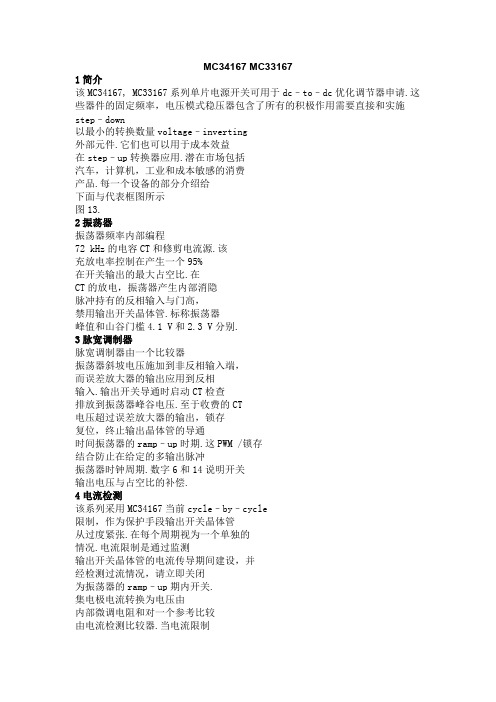
MC34167 MC331671简介该MC34167, MC33167系列单片电源开关可用于dc–to–dc优化调节器申请.这些器件的固定频率,电压模式稳压器包含了所有的积极作用需要直接和实施step–down以最小的转换数量voltage–inverting外部元件.它们也可以用于成本效益在step–up转换器应用.潜在市场包括汽车,计算机,工业和成本敏感的消费产品.每一个设备的部分介绍给下面与代表框图所示图13.2振荡器振荡器频率内部编程72 kHz的电容CT和修剪电流源.该充放电率控制在产生一个95%在开关输出的最大占空比.在CT的放电,振荡器产生内部消隐脉冲持有的反相输入与门高,禁用输出开关晶体管.标称振荡器峰值和山谷门槛4.1 V和2.3 V分别.3脉宽调制器脉宽调制器由一个比较器振荡器斜坡电压施加到非反相输入端,而误差放大器的输出应用到反相输入.输出开关导通时启动CT检查排放到振荡器峰谷电压.至于收费的CT电压超过误差放大器的输出,锁存复位,终止输出晶体管的导通时间振荡器的ramp–up时期.这PWM /锁存结合防止在给定的多输出脉冲振荡器时钟周期.数字6和14说明开关输出电压与占空比的补偿.4电流检测该系列采用MC34167当前cycle–by–cycle限制,作为保护手段输出开关晶体管从过度紧张.在每个周期视为一个单独的情况.电流限制是通过监测输出开关晶体管的电流传导期间建设,并经检测过流情况,请立即关闭为振荡器的ramp–up期内开关.集电极电流转换为电压由内部微调电阻和对一个参考比较由电流检测比较器.当电流限制达到阈值,比较器重置PWM 锁存.限流门限点往往设在6.5 A.图9说明开关与输出电流限制门槛温度.5误差放大器和参考一个误差放大器的高增益提供了访问反相输入和输出.该放大器具有典型dc电压增益80 dB,和单位增益带宽600 kHz与相边缘 70度(图3).同相输入偏置内部5.05 V参考并且不固定了.参考具有精度±2.0%在室温下.以提供负载5.0 V中,参考编程50以上mV 5.0 V补偿在电缆的电压降和1.0%从连接器转换器输出.如果转换器设计需要一个输出电压高于5.05 V,电阻更大R1必须加入形成一个分压网络的反馈输入中所示数字13和18.了确定输出方程与分压网络的电压为:Vout+5.05R2R1)1外部回路补偿所需的转换器稳定.一个简单的low–pass滤波器是由连接电阻(R2)从稳压输出到反相输入,以及一系列resistor–capacitor (RF, CF)之间Pins 1和5.补偿网络的元件值显示在电路的申请被选定为each在稳定工作条件下进行测试.该step–down转换器(图18)是最容易补偿稳定.该step–up(图20)和voltage–inverting(图22)配置运作,连续导反激式转换器,而且更难以弥补.该最简单的方法来优化网络是补偿观察输出电压的负载响应一步变化,而调整临界阻尼RF和CF.该最终电路应验证以下四个稳定边界条件.这些条件是最小和最大输入电压,最小和最大负载.通过箝位的电压误差放大器的输出(引脚5)不到150 mV,内部电路将放置到一个低功耗待机模式,从而将权力电源电流36µA与12 V电源电压.图10说明了备用电源电流与电源电压.误差放大器的输出有一个100µA电流源pull–up,可用于实现soft–start.图17显示充电电流源通过一个电容CSS系列二极管.该二极管断开从反馈CSS回路电阻时1.0 M操作它上面的收费销5.范围开关输出输出开关晶体管的设计最大的40 V,以最小的峰值集电极电流时5.5 A.配置为step–down或voltage–inverting应用,如在图18和22,电感会把偏置的输出整流开关关闭时.整流器与较高的正向电压降或长期拖延的时间应该打开不能使用.如果发射器被允许去充分负,集电极电流流过,造成额外的装置暖气,降低转换效率.图8显示到箝位的发射器0.5集电极电流V,在一系列的100µA温度过高.阿1N5825或肖特基势垒整流器相当于推荐履行这些要求.欠压分离欠压分离一直比较成立以保证完全集成电路在输出级的功能已启用.内部参考电压比较器的监测使输出阶段VCC超过5.9 V.为了防止不稳定的输出交叉切换的阈值,0.9 V迟滞.6摩托罗拉设备数据模拟ICMC34167 MC33167热保护内部热关断电路,以保护在事件集成电路的最大结温度超过.当被激活时,通常在170°C,是被迫的锁存成'复位'的状态,关闭输出开关.此功能防止灾难性故障提供偶然的设备过热.它的目的不是要作为一个适当的散热片的替代品.该MC34167包含在5–lead TO–220类型包装.该标签包装是很常见的中心引脚(引脚3),通常连接到地.设计考虑不要试图建立一个转换器上wire–wrap或plug–in原型板.特别应注意分开的信号电流和接地接地通路从负载电流路径.所有高电流回路应尽可能短尽可能使用重型铜runs到尽量减少振荡和辐射EMI.为了获得最佳的操作,严密元件布局建议.电容器Cin, CO,和所有的反馈元件应尽可能靠近IC在身体可能.这也是必须的肖特基二极管连接到开关输出是尽可能靠近尽可能IC.图15.低功耗待机电路+100µA错误放大器1图16.过电压关断电路+100µA错误放大器1120补偿5120补偿R15R1I =待机模式VShutdown = VZener + 0.7图17. Soft–Start电路+100µA错误放大器1120补偿D2Vin1.0 MCss5D1R1tSoft–Start≈35,000 Css。
MAX6163AESA-T中文资料

General DescriptionThe MAX6161–MAX6168 are precision, low-dropout,micropower voltage references. These three-terminal devices operate with an input voltage range from (V OUT + 200mV) to 12.6V and are available with output volt-age options of 1.25V, 1.8V, 2.048V, 2.5V, 3V, 4.096V,4.5V, and 5V. They feature a proprietary curvature-cor-rection circuit and laser-trimmed thin-film resistors that result in a very low temperature coefficient of 5ppm/°C (max) and an initial accuracy of ±2mV (max).Specifications apply to the extended temperature range (-40°C to +85°C).The MAX6161–MAX6168 typically draw only 100µA of supply current and can source 5mA (4mA for MAX6161) or sink 2mA of load current. Unlike conven-tional shunt-mode (two-terminal) references that waste supply current and require an external resistor, these devices offer a supply current that is virtually indepen-dent of the supply voltage (8µA/V variation) and do not require an external resistor. Additionally, the internally compensated devices do not require an external com-pensation capacitor. Eliminating the external compen-sation capacitor saves valuable board area in space-critical applications. A low-dropout voltage and a supply-independent, ultra-low supply current make these devices ideal for battery-operated, high-perfor-mance, low-voltage systems.The MAX6161–MAX6168 are available in 8-pin SO packages.________________________ApplicationsAnalog-to-Digital Converters (ADCs)Portable Battery-Powered Systems Notebook Computers PDAs, GPS, DMMs Cellular PhonesPrecision +3V/+5V Systems____________________________Features♦±2mV (max) Initial Accuracy♦5ppm/°C (max) Temperature Coefficient ♦5mA Source Current at 0.9mV/mA ♦2mA Sink Current at 2.5mV/mA ♦Stable with 1µF Capacitive Loads ♦No External Capacitor Required ♦100µA (typ) Quiescent Supply Current ♦200mV (max) Dropout at 1mA Load Current ♦Output Voltage Options: 1.25V, 1.8V, 2.048V, 2.5V,3V, 4.096V, 4.5V, 5V19-1650; Rev 3; 8/05MAX6161–MAX6168Precision, Micropower, Low-Dropout, High-Output-Current, SO-8 Voltage References________________________________________________________________Maxim Integrated Products 1___________________Pin Configuration*Insert the code for the desired initial accuracy and temperature coefficient (from the Selector Guide) in the blank to complete the part number.Typical Operating Circuit and Selector Guide appear at end of data sheet.Ordering InformationFor pricing, delivery, and ordering information,please contact Maxim/Dallas Direct!at 1-888-629-4642, or visit Maxim’s website at .M A X 6161–M A X 6168Precision, Micropower, Low-Dropout, High-Output-Current, SO-8 Voltage References 2_______________________________________________________________________________________ABSOLUTE MAXIMUM RATINGSStresses beyond those listed under “Absolute Maximum Ratings” may cause permanent damage to the device. These are stress ratings only, and functional operation of the device at these or any other conditions beyond those indicated in the operational sections of the specifications is not implied. Exposure to absolute maximum rating conditions for extended periods may affect device reliability.Voltages Referenced to GNDIN …………............................................................-0.3 to +13.5V OUT………………........................................-0.3V to (V IN + 0.3V)Output Short-Circuit Duration to GND or IN (V IN ≤6V)...Continuous Output Short-Circuit Duration to GND or IN (V IN > 6V)…...........60sContinuous Power Dissipation (T A = +70°C)8-Pin SO (derate 5.88mW/°C above +70°C)...............471mW Operating Temperature Range ...........................-40°C to +85°C Storage Temperature Range………….…………-65°C to +150°C Lead Temperature (soldering, 10s)……………………….+300°CELECTRICAL CHARACTERISTICS—MAX6161 (V OUT = 1.25V)MAX6161–MAX6168Precision, Micropower, Low-Dropout, High-Output-Current, SO-8 Voltage References_______________________________________________________________________________________3ELECTRICAL CHARACTERISTICS—MAX6168 (V OUT = 1.800V)M A X 6161–M A X 6168Precision, Micropower, Low-Dropout, High-Output-Current, SO-8 Voltage References 4_______________________________________________________________________________________ELECTRICAL CHARACTERISTICS—MAX6162 (V OUT = 2.048V)MAX6161–MAX6168Precision, Micropower, Low-Dropout, High-Output-Current, SO-8 Voltage References_______________________________________________________________________________________5ELECTRICAL CHARACTERISTICS—MAX6166 (V OUT = 2.500V)M A X 6161–M A X 6168Precision, Micropower, Low-Dropout, High-Output-Current, SO-8 Voltage References 6_______________________________________________________________________________________ELECTRICAL CHARACTERISTICS —MAX6163 (V OUT = 3.000V)MAX6161–MAX6168Precision, Micropower, Low-Dropout, High-Output-Current, SO-8 Voltage References_______________________________________________________________________________________7ELECTRICAL CHARACTERISTICS—MAX6164 (V OUT = 4.096V)M A X 6161–M A X 6168Precision, Micropower, Low-Dropout, High-Output-Current, SO-8 Voltage References 8_______________________________________________________________________________________ELECTRICAL CHARACTERISTICS —MAX6167 (V OUT = 4.500V)MAX6161–MAX6168Precision, Micropower, Low-Dropout, High-Output-Current, SO-8 Voltage References_______________________________________________________________________________________9ELECTRICAL CHARACTERISTICS—MAX6165 (V OUT = 5.000V)Note 2:Temperature Coefficient is specified by the “box” method; i.e., the maximum ΔV OUT is divided by the maximum ΔT.Note 3:Thermal Hysteresis is defined as the change in T A = +25°C output voltage before and after temperature cycling of thedevice (from T A = T MIN to T MAX ). Initial measurement at T A = +25°C is followed by temperature cycling the device to T A = +85°C then to T A = -40°C, and another measurement at T A = +25°C is compared to the original measurement at T A = +25°C.Note 4:Dropout voltage is the minimum input voltage at which V OUT changes ≤0.2% from V OUT at V IN = 5.0V (V IN = 5.5V forMAX6165).M A X 6161–M A X 6168Precision, Micropower, Low-Dropout, High-Output-Current, SO-8 Voltage References 10______________________________________________________________________________________Typical Operating Characteristics(V IN = +5V for MAX6161–MAX6168, V IN = +5.5V for MAX6165, I OUT = 0, T A = +25°C, unless otherwise noted.) (Note 5)MAX6161OUTPUT VOLTAGE TEMPERATURE DRIFTTEMPERATURE (°C)O U T P U T V O L T A G E (V )70552540-1010-251.24961.24971.24981.24991.25001.25011.25021.25031.25041.25051.2495-4085MAX6165OUTPUT VOLTAGE TEMPERATURE DRIFTTEMPERATURE (°C)O U T P U T V O L T A G E (V )7055-25-102510404.99854.99904.99955.00005.00055.00105.00155.00204.9980-4085MAX6161LONG-TERM DRIFTM A X 6161/68 t o c 03TIME (hrs)D R I F T (p p m )768192384576-30-20-100102030405060-40960MAX6165LONG-TERM DRIFTM A X 6161/68 t o c 04TIME (hrs)D R I F T (p p m )768192384576-90-80-70-60-50-40-30-20-100-100960-300-200-100010020030024681012MAX6161LINE REGULATIONINPUT VOLTAGE (V)O U T P U T V O L T A G E C H A N G E (μV )-1200-600-800-1000-400-20002005971113MAX6165LINE REGULATIONINPUT VOLTAGE (V)O U T P U T V O L T A G E C H A N G E (μV )-310-1-22345-4-224LOAD CURRENT (mA)O U T P U T V O L T A G E C H A N G E (m V)MAX6161LOAD REGULATION-620-2-44861012-6-2-4246LOAD CURRENT (mA)O U T P U T V O L T A G E C H A N G E (m V )MAX6165LOAD REGULATION0.100.050.200.150.250.30021345MAX6166DROPOUT VOLTAGE vs. LOAD CURRENTLOAD CURRENT (mA)D R O P O U T V O L T A GE (V )MAX6161–MAX6168Output-Current, SO-8 Voltage References______________________________________________________________________________________11Typical Operating Characteristics (continued)(V IN = +5V for MAX6161–MAX6168, V IN = +5.5V for MAX6165, I OUT = 0, T A = +25°C, unless otherwise noted.) (Note 5)00.050.150.100.200.2521345LOAD CURRENT (mA)D R O P O U T V O L T A GE (V )MAX6165DROPOUT VOLTAGE vs. LOAD CURRENTM A X 6161/68 t o c 11FREQUENCY (kHz)P S R R (d B )0-10-20-30-40-50-60-70-80-900.0011101000.010.11000MAX6161POWER-SUPPLY REJECTION RATIOvs. FREQUENCY-70-800.001101000-60-50-40-30-20-100FREQUENCY (kHz)P S R R (d B )0.1MAX6165POWER-SUPPLY REJECTION RATIOvs. FREQUENCYM A X 6161/68 t c 12MAX6161SUPPLY CURRENT vs. SUPPLY VOLTAGESUPPLY VOLTAGE (V)S U P P L Y C U R R E N T (μA )1210864108116124132140148156164172180100214MAX6165SUPPLY CURRENT vs. SUPPLY VOLTAGESUPPLY VOLTAGE (V)S U P P L Y C U R R E N T (μA )1312101178969610210811412012613213814415090514MAX6161SUPPLY CURRENT vs. TEMPERATURETEMPERATURE (°C)S U P P L Y C U R R E N T (μA )603510-15108116124132140148156164172180100-4085MAX6165SUPPLY CURRENT vs. TEMPERATURETEMPERATURE (°C)S U P P L Y C U R R E N T (μA )603510-159610210811412012613213814415090-408500.00110100040206080100140120160180200220M A X 6161/68 t o c 17FREQUENCY (kHz)O U T P U T I M P E D A N C E (Ω)0.1MAX6161OUTPUT IMPEDANCE vs. FREQUENCY1800.00110100040206010080120140160M A X 6161/68 t o c 18FREQUENCY (kHz)O U T P U T I M P E D A N C E (Ω)0.1MAX6165OUTPUT IMPEDANCE vs. FREQUENCYM A X 6161–M A X 6168Output-Current, SO-8 Voltage References 12______________________________________________________________________________________Typical Operating Characteristics (continued)(V IN = +5V for MAX6161–MAX6168, V IN = +5.5V for MAX6165, I OUT = 0, T A = +25°C, unless otherwise noted.) (Note 5)V OUT 10μV/div 1s/div MAX61610.1Hz TO 10Hz OUTPUT NOISEM A X 6161/68 t o c 19V OUT 10μV/div1s/divMAX6165NOISEM A X 6161/68 t o c 20V OUT 500mV/divV IN 5V/div10μs/divMAX6161TURN-ON TRANSIENT(C L = 50pF)M A X 6161/68 t o c 21V OUT 2V/divV IN 5V/div40μs/divMAX6165TURN-ON TRANSIENT(C L = 50pF)M A X 6161/67 t o c 22I OUT 500μA/divV OUTAC-COUPLED 100mV/div400μs/div MAX6161LOAD TRANSIENT(I OUT = ±250μA, V IN = 5.0, C L = 0)+250μA -250μAMAX6161/68 toc23I OUT 500μA/divV OUTAC-COUPLED50mV/div400μs/divMAX6165LOAD TRANSIENT(I OUT = ±250μA, C L = 0, V IN = 5.5V)+250μA -250μAMAX6161/68 toc24MAX6161–MAX6168Output-Current, SO-8 Voltage References______________________________________________________________________________________13I OUT 5mA/divV OUTAC-COUPLED50mV/div400μs/divMAX6165LOAD TRANSIENT(C L = 0, I OUT = ±2mA, V IN = 5.5V)+2mA -2mAMAX6161/68 toc28I OUT 5mA/divV OUTAC-COUPLED 100mV/div 400μs/div MAX6161LOAD TRANSIENT(V IN = 5.0V, C L = 0, I OUT = ±2mA)+2mA-2mAMAX6161/68 toc27I OUT 5mA/divV OUTAC-COUPLED50mV/div400μs/divMAX6161LOAD TRANSIENT(V IN = 5.0V, C L = 1μF, I OUT = ±2mA)+2mA-2mAMAX6161/68 toc29I OUT 5mA/divV OUTAC-COUPLED20mV/div400μs/divMAX6165LOAD TRANSIENT(C L = 1μF, I OUT = ±2mA, V IN = 5.5V)+2mA-2mAMAX6161/68 toc30I OUT 500μA/divV OUTAC-COUPLED10mV/div 400μs/div MAX6161LOAD TRANSIENT(I OUT = ±250μA, V IN = 5.0V, C L = 1μF)+250μA -250μAMAX6161/68 toc25I OUT 500μA/divV OUTAC-COUPLED20mV/div400μs/divMAX6165LOAD TRANSIENT(I OUT = ±250μA, C L = 1μF, V IN = 5.5V)+250μA-250μAMAX6161/68 toc26Typical Operating Characteristics (continued)(V IN = +5V for MAX6161–MAX6168, V IN = +5.5V for MAX6165, I OUT = 0, T A = +25°C, unless otherwise noted.) (Note 5)M A X 6161–M A X 6168Output-Current, SO-8 Voltage References 14______________________________________________________________________________________I OUT 5mA/divV OUTAC-COUPLED50mV/div 400μs/div MAX6161LOAD TRANSIENT(V IN = 5.0V, C L = 1μF, I OUT = ±4mA)+4mA-4mAMAX6161/68 toc33I OUT 5mA/divV OUTAC-COUPLED50mV/div400μs/divMAX6165LOAD TRANSIENT(I OUT = ±5mA, C L = 1μF, V IN = 5.5V)+5mA-5mAMAX6161/68 toc34V IN500mV/divV OUTAC-COUPLED20mV/div 40μs/div MAX6161LINE TRANSIENT(C L = 0)+0.25V-0.25VMAX6161/68 toc35V IN500mV/divV OUTAC-COUPLED20mV/div40μs/divMAX6165LINE TRANSIENT(C L = 0)+0.25V -0.25VMAX6161/68 toc36Note 5:Many of the Typical Operating Characteristics of the MAX6161 family are extremely similar. The extremes of these characteristicsare found in the MAX6161 (1.25V output) and the MAX6165 (5.0V output). The Typical Operating Characteristics of the remain-der of the MAX6161 family typically lie between these two extremes and can be estimated based on their output voltages.Typical Operating Characteristics (continued)(V IN = +5V for MAX6161–MAX6168, V IN = +5.5V for MAX6165, I OUT = 0, T A = +25°C, unless otherwise noted.) (Note 5)I OUT 5mA/divV OUTAC-COUPLED 200mV/div400μs/div MAX6161LOAD TRANSIENT(V IN = 5.0V, C L = 0, I OUT = ±4mA)+4mA-4mAMAX6161/68 toc31I OUT 5mA/divV OUTAC-COUPLED 100mV/div400μs/divMAX6165LOAD TRANSIENT(I OUT = ±5mA, C L = 0, V IN = 5.5V)+5mA-5mAMAX6161/68 toc32MAX6161–MAX6168Output-Current, SO-8 Voltage References______________________________________________________________________________________15Applications InformationInput BypassingF or the best line-transient performance, decouple the input with a 0.1µF ceramic capacitor as shown in the Typical Operating Circuit . Locate the capacitor as close to IN as possible. When transient performance is less important, no capacitor is necessary.Output/Load CapacitanceDevices in the MAX6161 family do not require an output capacitor for frequency stability. In applications where the load or the supply can experience step changes,an output capacitor of at least 0.1µF will reduce the amount of overshoot (undershoot) and improve the cir-cuit’s transient response. Many applications do not require an external capacitor, and the MAX6161 family can offer a significant advantage in applications when board space is critical.Supply CurrentThe quiescent supply current of the series-mode MAX6161 family is typically 100µA and is virtually inde-pendent of the supply voltage, with only an 8µA/V (max) variation with supply voltage. Unlike series refer-ences, shunt-mode references operate with a series resistor connected to the power supply. The quiescent current of a shunt-mode reference is thus a function of the input voltage. Additionally, shunt-mode references have to be biased at the maximum expected load cur-rent, even if the load current is not present at the time.In the MAX6161 family, the load current is drawn from the input voltage only when required, so supply current is not wasted and efficiency is maximized at all input voltages. This improved efficiency reduces power dissi-pation and extends battery life.When the supply voltage is below the minimum speci-fied input voltage (as during turn-on), the devices can draw up to 400µA beyond the nominal supply current.The input voltage source must be capable of providing this current to ensure reliable turn-on.Output Voltage HysteresisOutput voltage hysteresis is the change in the input voltage at T A = +25°C before and after the device is cycled over its entire operating temperature range.Hysteresis is caused by differential package stress appearing across the bandgap core transistors. The typical temperature hysteresis value is 125ppm.Turn-On TimeThese devices typically turn on and settle to within 0.1% of their final value in 50µs to 300µs, depending on the output voltage (see electrical table of part used).The turn-on time can increase up to 1.5ms with the device operating at the minimum dropout voltage and the maximum load.Typical Operating Circuit__________________________Chip Information TRANSISTOR COUNT: 117PROCESS: BiCMOSPin DescriptionPIN NAME FUNCTIONNo Connection. Not internally connected.N.C.1, 3, 5, 7, 82IN Input Voltage GroundGND 46OUTReference OutputM A X 6161–M A X 6168Output-Current, SO-8 Voltage References 16______________________________________________________________________________________Selector GuideMAX6161–MAX6168Maxim cannot assume responsibility f or use of any circuitry other than circuitry entirely embodied in a Maxim product. No circuit patent licenses are implied. Maxim reserves the right to change the circuitry and specifications without notice at any time.Maxim Integrated Products, 120 San Gabriel Drive, Sunnyvale, CA 94086 408-737-7600_____________________17©2005 Maxim Integrated ProductsPrinted USAis a registered trademark of Maxim Integrated Products, Inc.S O I C N .E P SOutput-Current, SO-8 Voltage ReferencesPackage Information(The package drawing(s) in this data sheet may not reflect the most current specifications. For the latest package outline information go to /packages .)。
FM33256_FM3316_中文数据手册
• 无需等待的写入
实时时钟/日历
• 根据1备份当前
µA
• 秒通过BCD格式的世纪
• 跟踪闰年到2099年
• 使用标准的32.768 kHz晶振
• 软件校准
• 支持电池或电容备份
快速SPI接口
• 高达16 MHz最大总线频率
• •
通过SPI接口RTC,监事受控 SPI模式0&3(CPOL,CPHA = 0,0&1,1)
易• 于使经用营的从配2.7置到3.6V • 小脚印“绿色”14引脚SOIC(-G) • 低工作电流,50µA待机电流 • -40°C至+85°C操作 • 保险商实验室(UL)认证
描述
该FM33256和FM3316是集成设备 F-RAM存储器的最常用的 功能处理器的系统.主要
功能包括非易失性存储器,实时时钟, low-V DD 复位,看门狗定时器,非易失性事件 计数器,可锁定的64位的序列号区域和通用比较器,它可 用于一个电源失效(NMI)中断或其他目的.这些器件工作 在2.7V至3.6V.
水平.后t
RPU 已经得到满足,/ RST引脚将
返回到弱上拉状态.当/ RST断言,
串行总线活动被锁定,即使交易
发生为V
DD 下降到低于V
TP .内存
操作开始,而V
DD 以上V
TP 将
在内部完成.
内存操作
该FM33xx产品都可以在16Kb的和256Kb的内存大小.这两种 器件是软件兼容;也就是说,这两个版本使用一致的 twobyte寻址的存储设备.这使得这两个设备相同的独立的存储 器对应,如FM25L16.
该处理器伴侣包括通常需要 CPU的支持功能.监督职能
包括由一个控制的复位输出信号
MC33161PG资料

Recommended Operating Conditions is not implied. Extended exposure to stresses above the Recommended Operating Conditions may affect
device reliability.
2. Maximum package power dissipation must be observed.
3. Tlow = 0°C for MC34161 −40°C for MC33161
Thigh = +70°C for MC34161 +105°C for MC33161
−40°C for NCV33161
Operating Junction Temperature
Operating Ambient Temperature (Note 3) MC34161 MC33161 NCV33161
VCC Vin ISink Vout
PD RqJA PD RqJA RqJA
TJ TA
40
V
− 1.0 to +40
元器件交易网
MC34161, MC33161, NCV33161
Universal Voltage Monitors
The MC34161/MC33161 are universal voltage monitors intended for use in a wide variety of voltage sensing applications. These devices offer the circuit designer an economical solution for positive and negative voltage detection. The circuit consists of two comparator channels each with hysteresis, a unique Mode Select Input for channel programming, a pinned out 2.54 V reference, and two open collector outputs capable of sinking in excess of 10 mA. Each comparator channel can be configured as either inverting or noninverting by the Mode Select Input. This allows over, under, and window detection of positive and negative voltages. The minimum supply voltage needed for these devices to be fully functional is 2.0 V for positive voltage sensing and 4.0 V for negative voltage sensing.
试验机软件MaxTest说明书

目录第一章简介 (4)一、前言 (4)二、特点 (4)三、控制性能 (4)第二章安装和运行 (6)一、运行环境 (6)二、安装 (6)三、卸载 (9)四、修复 (9)第三章界面操作 (10)一、主窗口 (10)二、力和变型显示板 (12)三、位移显示板 (13)四、曲线显示板 (14)五、控制板 (17)六、刻度板 (23)七、数据板 (24)八、分析板 (27)九、调试参数窗口 (28)第四章试验过程 (32)一、选择试验类型 (32)二、输入试件信息 (32)三、打开历史数据 (32)四、试验操作 (37)五、结果保存 (40)六、数据分析 (40)七、报告打印 (43)第五章系统设置和调整 (46)一、关于试验力过载 (46)二、系统设置 (46)三、选择力传感器和引伸计 (51)四、标定校正 (51)五、硬件调零 (52)六、检定记录 (52)七、控制观察 (53)八、增加试验方法 (54)九、重新注册 (55)十、用户自定义项目 (55)十一、保存调试参数文件 (56)第六章调试工具箱MaxIni使用说明 (57)一、安装和运行 (57)二、使用 (57)第七章程序编制和程序执行 (62)一、用途 (62)二、程序执行 (62)三、程序编制 (63)第八章批量处理MaxBatch使用说明 (70)一、用途 (70)二、安装 (70)三、操作 (70)第九章如何利用Word或Excel打印报表 (76)一、简介 (76)二、安装 (76)三、MaxDoc使用 (77)四、MaxXls使用 (80)第十章如何重新压环检定力传感器 (82)一、察看测量方式和控制方式 (82)二、有手动控制分档测量系统的检定 (83)三、有手动控制不分档测量系统的检定 (84)四、无手动控制分档测量系统的检定 (86)五、无手动控制不分档测量系统的检定 (88)六、注意事项 (91)第十一章错误信息 (92)一、安装时 (92)二、启动时 (92)三、运行时 (93)第十二章AD700/800万能试验卡 (94)一、概述 (94)二、安装和拆卸 (94)三、检测硬件是否正常(PCIADTEST软件使用方法) (96)四、传感器接口定义 (97)第十三章高级自定义报告打印格式 (98)一、为什么要自定义报告打印格式 (98)二、特点 (98)三、art文件 (98)四、srt文件 (106)第十四章使用Micorsoft Excel打印报表 (112)修订2005年8月16日第一章简介一、前言MaxTest程序根据不同的配置参数,适用于不同的类型的材料试验机,如微机屏显万能试验机、微机控制电液伺服万能试验机、微机控制电液比例万能试验机以及微机控制电子万能试验机等。
MAXIM MAX336 MAX337 数据手册

现货库存、技术资料、百科信息、热点资讯,精彩尽在鼎好!_______________General DescriptionThe MAX336/MAX337 are monolithic, CMOS analog multiplexers (muxes). The 16-channel MAX336 is designed to connect one of 16 inputs to a common out-put by control of a 4-bit binary address. The dual,8-channel MAX337 is designed to connect one of eight inputs to a common output by control of a 3-bit binary address. Both devices can be used as either a mux or a demux. On-resistance is 400Ω(max), and the devices conduct current equally well in both directions.These muxes feature extremely low off leakages (less than 20pA at +25°C) and on-channel leakages (less than 50pA at +25°C). The new design offers guaranteed low charge injection (3.5pC typical) and electrostatic dis-charge (ESD) protection greater than 2000V, per method 3015.7. These improved muxes are pin-compatible upgrades for the industry-standard DG506 and DG507. The MAX336/MAX337 operate from a single +4.5V to +30V supply or from dual ±4.5V to ±20V supplies. All control inputs (whether address or enable) are TTL compatible (0.8V to 2.4V) over the full specified temper-ature range and over the ±4.5V to ±18V supply range.________________________ApplicationsPrecision Data Acquisition Precision Signal Routing Test Equipment____________________________Featureso <400Ω(max) On-Resistance o <500ns Transition Time o <10ΩOn-Resistance Matcho <20pA NO-Off Leakage Current at +25°C o 3.5pC Charge Injection o +4.5V to +30V Single Supply ±4.5V to ±20V Dual Supplieso Plug-In Upgrade for Industry-Standard DG506/DG507o Bidirectional Rail-to-Rail ®Signal Handling o TTL/CMOS-Logic Compatibleo >2000V ESD Protection, per Method 3015.7______________Ordering InformationMAX336/MAX33716-Channel/Dual 8-Channel,Low-Leakage, CMOS Analog Multiplexers________________________________________________________________Maxim Integrated Products1_____________________Pin Configurations/Functional Diagrams/Truth Tables19-1193; Rev 0; 4/97Ordering Information continued at end of data sheet.*Contact factory for dice specifications.For free samples & the latest literature: , or phone 1-800-998-8800Rail-to-Rail is a registered trademark of Nippon Motorola Ltd.M A X 336/M A X 33716-Channel/Dual 8-Channel,Low-Leakage, CMOS Analog Multiplexers 2_______________________________________________________________________________________ABSOLUTE MAXIMUM RATINGSELECTRICAL CHARACTERISTICS—Dual Supplies(V+ = +15V, V- = -15V, GND = 0V, V AH = +2.4V, V AL = +0.8V, T A = T MIN to T MAX , unless otherwise noted.)Stresses beyond those listed under “Absolute Maximum Ratings” may cause permanent damage to the device. These are stress ratings only, and functional operation of the device at these or any other conditions beyond those indicated in the operational sections of the specifications is not implied. Exposure to absolute maximum rating conditions for extended periods may affect device reliability.Voltage Referenced to V-V+............................................................................-0.3V, 44V GND.........................................................................-0.3V, 25V Digital Inputs, A_, EN_, NO, COM(Note 1).............................................(V- - 0.3V) to (V+ + 0.3V)or 30mA (whichever occurs first)Continuous Current (any terminal)......................................30mA Peak Current, NO or COM(pulsed at 1ms, 10% duty cycle max)..........................100mA Continuous Power Dissipation (T A = +70°C)Plastic DIP (derate 14.29mW/°C above +70°C)............1.14WWide SO (derate 12.50mW/°C above +70°C).................1.00W SSOP (derate 9.52mW/°C above +70°C).....................762mW CERDIP (derate 16.67mW/°C above +70°C)..................1.33W Operating Temperature RangesMAX336C_I/MAX337C_I......................................0°C to +70°C MAX336E_I/MAX337E_I....................................-40°C to +85°C MAX336MJI/MAX337MJI................................-55°C to +125°C Storage Temperature Range.............................-65°C to +150°C Lead Temperature (soldering, 10sec).............................+300°CNote 1:Signals on any terminal exceeding V+ or V- are clamped by internal diodes. Limit forward current to maximum current rating.MAX336/MAX33716-Channel/Dual 8-Channel,Low-Leakage, CMOS Analog Multiplexers_______________________________________________________________________________________3ELECTRICAL CHARACTERISTICS—Dual Supplies (continued)(V+ = +15V, V- = -15V, GND = 0V, V AH = +2.4V, V AL = +0.8V, T A = T MIN to T MAX , unless otherwise noted.)M A X 336/M A X 33716-Channel/Dual 8-Channel,Low-Leakage, CMOS Analog Multiplexers 4_______________________________________________________________________________________ELECTRICAL CHARACTERISTICS—Single Supply(V+ = +12V, V- = 0V, GND = 0V, V AH = +2.4V, V AL = +0.8V, T A = T MIN to T MAX , unless otherwise noted.)Note 2:The algebraic convention where the most negative value is a minimum and the most positive value a maximum is used inthis data sheet.Note 3:Guaranteed by design.Note 4:∆R ON = R ON(MAX)- R ON(MIN).Note 5:Leakage parameters are 100% tested at the maximum rated hot temperature and guaranteed by correlation at T A = +25°C.Note 6:Worst-case isolation is on channel 4 because of its proximity to the drain pin. Off isolation = 20log V COM /V NO , whereV COM = output and V NO = input to off switch.-100-90-80-70-60-50-40-30-20-1000.110100FREQUENCY RESPONSE225-225-90-45045-135-18090135180FREQUENCY (MHz)L O S S (d B )P H A S E (D E G R E E S )11000.0011010k1k 100100kTOTAL HARMONIC DISTORTIONvs. FREQUENCY0.01FREQUENCY (Hz)T H D (%)10.1101001010.10.010.00010.0010.00001V IN (V)3691215SUPPLY CURRENT I + (µA )__________________________________________Typical Operating Characteristics(T A = +25°C, unless otherwise noted.)MAX336/MAX33716-Channel/Dual 8-Channel,Low-Leakage, CMOS Analog Multiplexers_______________________________________________________________________________________57006005004003001002000V COM (V)-10-15-20-505101520ON-RESISTANCE vs. V R O N (Ω)350300250200150100500-10-15-5010515ON-RESISTANCE vs. V COM OVER TEMPERATURE (DUAL SUPPLIES)R O N (Ω)V COM (V)180016001400120010008004002006000V COM (V)4268101214161820ON-RESISTANCE vs. V COM(SINGLE SUPPLY)R O N (Ω)500450400350300250200501501000V COM (V)4268121014ON-RESISTANCE vs. V COM OVER TEMPERATURE (SINGLE SUPPLY)R O N (Ω)1086420-4-2-6V COM (V)-10-15-5051015CHARGE INJECTIONvs. V Q j (p C)100.0001-55125OFF LEAKAGE vs. TEMPERATURE1TEMPERATURE (°C)O F F L E A K A G E (n A )250.010.001-35-15650.1100100045851055100.0001-55125ON LEAKAGE vs. TEMPERATURE1TEMPERATURE (°C)O N L E A K A G E (n A )250.010.001-35-15650.11001000458510551000.001-55125SUPPLY CURRENT vs. TEMPERATURE10TEMPERATURE (°C)I +, I - (µA )250.10.01-35-1565145851055100010009008007006005004001003002000SUPPLY VOLTAGE (V)76891051112141315TRANSITION TIME vs. POWER SUPPLIESt T R A N S (n s )____________________________Typical Operating Characteristics (continued)(T A = +25°C, unless otherwise noted.)__________Applications InformationOperation with Supply Voltages Other than 15VUsing supply voltages less than ±15V will reduce the analog signal range. The MAX336/MAX337 switches operate with ±4.5V to ±20V bipolar supplies or with a +4.5V to +30V single supply. Connect V- to GND when operating with a single supply. Both device types can also operate with unbalanced supplies such as +24V and -5V. The Typical Operating Characteristics graphs show typical on-resistance with 20V, 15V, 10V, and 5V supplies. (Switching times increase by a factor of two or more for operation at 5V.)Overvoltage ProtectionProper power-supply sequencing is recommended for all CMOS devices. Do not exceed the absolute maxi-mum ratings, because stresses beyond the listed rat-ings may cause permanent damage to the devices.Always sequence V+ on first, then V-, followed by the logic inputs NO and COM. If power-supply sequencing is not possible, add two small signal diodes in series with supply pins for overvoltage protection (Figure 1).Adding diodes reduces the analog signal range to 1V below V+ and 1V above V-, but does not significantly affect the devices’ low switch resistance and low leak-age characteristics. Device operation is unchanged,and the difference between V+ and V- should not exceed 44V.M A X 336/M A X 33716-Channel/Dual 8-Channel,Low-Leakage, CMOS Analog Multiplexers 6_____________________________________________________________________________________________________________________________________________________Pin DescriptionFigure 1. Overvoltage Protection Using External Blocking Diodes* Analog signal inputs and outputs are names of convenience only; they are identical and interchangeable.MAX336/MAX33716-Channel/Dual 8-Channel,Low-Leakage, CMOS Analog Multiplexers_______________________________________________________________________________________7______________________________________________Test Circuits/Timing DiagramsM A X 336/M A X 33716-Channel/Dual 8-Channel,Low-Leakage, CMOS Analog Multiplexers 8________________________________________________________________________________________________________________________Test Circuits/Timing Diagrams (continued)Figure 4. Break-Before-Make IntervalFigure 5. Charge Injection (V CTE )MAX336/MAX33716-Channel/Dual 8-Channel,Low-Leakage, CMOS Analog Multiplexers_______________________________________________________________________________________9_________________________________Test Circuits/Timing Diagrams (continued)Figure 6. Off Isolation Figure 7. CrosstalkFigure 8. NO/COM CapacitanceM A X 336/M A X 33716-Channel/Dual 8-Channel,Low-Leakage, CMOS Analog Multiplexers 10______________________________________________________________________________________________Pin Configurations/Functional Diagrams/Truth Tables (continued)MAX336/MAX33716-Channel/Dual 8-Channel,Low-Leakage, CMOS Analog Multiplexers______________________________________________________________________________________11__Ordering Information (continued)N.CGNDA2A1A0ENA3(N.C.)0.139"(3.53mm)0.092"(2.34mm)COM (COMA)V-N09(N01B)N010(N02B) N011(N03B)N012(N04B) N013(N05B) N014(N06B) N015(N07B) N016(N08B)N08(N08A)N07(N07A)N06(N06A)N05(N05A)N04(N04A)N03(N03A)N02(N02A)N01(N01A)( ) ARE FOR MAX337TRANSISTOR COUNT: 466BACKSIDE IS V+SUBSTRATE CONNECTED TO V+___________________Chip Topography*Contact factory for dice specifications.**Contact factory for availability.Maxim cannot assume responsibility for use of any circuitry other than circuitry entirely embodied in a Maxim product. No circuit patent licenses are implied. Maxim reserves the right to change the circuitry and specifications without notice at any time.12__________________Maxim Integrated Products, 120 San Gabriel Drive, Sunnyvale, CA 94086 (408) 737-7600©1997 Maxim Integrated ProductsPrinted USAis a registered trademark of Maxim Integrated Products.M A X 336/M A X 33716-Channel/Dual 8-Channel,Low-Leakage, CMOS Analog Multiplexers________________________________________________________________Package Information。
MC33161DMR2G中文资料

Operating Ambient Temperature (Note 3) MC34161 MC33161 NCV33161
VCC Vin ISink Vout
PD RqJA PD RqJA RqJA
TJ TA
40
V
− 1.0 to +40
Vth(CH 1)
Vref+0.15 Vref+0.23 Vref+0.30
V
Vth(CH 2)
0.3
0.63
0.9
COMPARATOR OUTPUTS Output Sink Saturation Voltage (ISink = 2.0 mA)
(ISink = 10 mA) (ISink = 0.25 mA, VCC = 1.0 V)
© Semiconductor Components Industries, LLC, 2006
1
June, 2006 − Rev. 9
MARKING DIAGRAMS
PDIP−8 P SUFFIX CASE 626
8
MC3x161P AWL
YYWWG
1
1
8
SOIC−8
Comparator Output Voltage
Power Dissipation and Thermal Characteristics (Note 2) P Suffix, Plastic Package, Case 626 Maximum Power Dissipation @ TA = 70°C Thermal Resistance, Junction−to−Air D Suffix, Plastic Package, Case 751 Maximum Power Dissipation @ TA = 70°C Thermal Resistance, Junction−to−Air DM Suffix, Plastic Package, Case 846A Thermal Resistance, Junction−to−Ambient
SIMATIC S7-300 分析输入模块 SM 331 数据资料说明书

Yes
No 2 Yes
500 V AC
40-pin
40 mm 125 mm 120 mm
272 g Feb 25, 2013
6ES7331-7NF10-0AB0 Page 4/4
03/05/2013
subject to modifications © Copyright Siemens AG 2013
03/05/2013
subject to modifications © Copyright Siemens AG 2013
Ni 1000 LG-Ni 1000 Ni 120 Ni 200 Ni 500 Pt 100 Pt 1000 Pt 200 Pt 500 Input ranges (rated values), resistors 0 to 150 ohms 0 to 300 ohms 0 to 600 ohms 0 to 6000 ohms Cable length Cable length, shielded, max. Analog value creation Measurement principle Integrations and conversion time/ resolution per channel Resolution with overrange (bit including sign), max.
Yes ; with external transmitter, current supply; possible with separate supply for transmitter Yes
+/- 0,1 % +/- 0,1 %
- 1、下载文档前请自行甄别文档内容的完整性,平台不提供额外的编辑、内容补充、找答案等附加服务。
- 2、"仅部分预览"的文档,不可在线预览部分如存在完整性等问题,可反馈申请退款(可完整预览的文档不适用该条件!)。
- 3、如文档侵犯您的权益,请联系客服反馈,我们会尽快为您处理(人工客服工作时间:9:00-18:30)。
________________________________________________________________ Maxim Integrated Products
For pricing, delivery, and ordering information, please contact Maxim/Dallas Direct! at 1-888-629-4642, or visit Maxim’s website at .
MAX3319
V-
________________________Applications
Palmtop Computers Hand-Held Instruments Pagers Cellular Phones GPS Handy Terminals Hand-Held Electronic Books
Note 1: V+ and V- can have maximum magnitudes of 7V, but their absolute difference cannot exceed 13V.
Stresses beyond those listed under “Absolute Maximum Ratings” may cause permanent damage to the device. These are stress ratings only, and functional operation of the device at these or any other conditions beyond those indicated in the operational sections of the specifications is not implied. Exposure to absolute maximum rating conditions for extended periods may affect device reliability.
元器件交易网
19-1751; Rev 0; 6/00
2.5V, 1µA, 460kbps, RS-232-Compatible Transceivers
General Description
The MAX3316–MAX3319 transceivers have a proprietary low-dropout transmitter output stage enabling RS-232compatible performance from +2.25V to +3.0V with a dual-charge pump. These devices require only four 0.1µF capacitors, and are guaranteed to operate at data rates up to 460kbps. The MAX3318/MAX3319 achieve a 1µA supply current using Maxim’s revolutionary AutoShutdown Plus™ feature. These devices automatically enter a low-power shutdown mode when the RS-232 cable is disconnected or the transmitters of the connected peripherals are inactive for more than 30 seconds. They turn on again when they sense a valid transition at any transmitter or receiver input. AutoShutdown Plus saves power without changes to the existing BIOS or operating system. The MAX3318 is a 2-Tx/2-Rx device while the MAX3319 is a 1-Tx/1-Rx device. These devices also feature a logic-level output (READY) that asserts when the charge pump is regulating and the device is ready to begin transmitting. The MAX3316/MAX3317 are 2-Tx/2-Rx transceivers. The MAX3317 features a 1µA shutdown mode that can be entered by driving SHDN low. The MAX3317’s receivers remain active while in shutdown mode, allowing external devices such as modems to be monitored using only 1µA supply current. These devices are available in space-saving packages: MAX3316 (16-pin SSOP and 20-pin TSSOP), MAX3317/ MAX3318 (20-pin SSOP and 20-pin TSSOP), and MAX3319 (16-pin SSOP).
Ordering Information continued at end of data sheet.
Typical Application Circuits
+2.5V CBYPASS C1 0.1µF 0.1µF 2 C1+ 4 C15 C2 0.1µF CMOS INPUT CMOS OUTPUT 6 C2+ C2T1OUT 13 15 VCC V+ 3 C3 0.1µF 7 C4 0.1µF RS-232COMPATIBLE OUTPUT RS-232COMPATIBLE INPUT
Features
o AutoShutdown Plus (MAX3318/MAX3319) o 300µA Operating Supply Current o 1µA Low-Power Shutdown with Receivers Active o Guaranteed 460kbps Data Rate o Guaranteed 4V/µs Slew Rate o RS-232 Compatible Down to 2.25V
AutoShutdown Plus is a trademark of Maxim Integrated Products. Pin Configurations appear at end of data sheet.
11 T1IN
9 R1OUT
R1IN 8 5k
1
R易网
2.5V, 1µA, 460kbps, RS-232-Compatible Transceivers MAX3316–MAX3319
ABSOLUTE MAXIMUM RATINGS
VCC to GND ..............................................................-0.3V to +6V V+ to GND (Note 1) ..................................................-0.3V to +7V V- to GND (Note 1) ...................................................-7V to +0.3V V+ + |V-| (Note 1) .................................................................+13V Input Voltages T_IN, EN, SHDN, FORCEON, FORCEOFF to GND ..................................................-0.3V to +6V R_IN to GND .....................................................................±25V Output Voltages T_OUT to GND ...............................................................±13.2V R_OUT, INVALID, READY to GND ..........-0.3V to (VCC + 0.3V) Short-Circuit Duration, T_OUT to GND.......................Continuous Continuous Power Dissipation (TA = +70°C) 16-Pin SSOP (derate 7.14mW/°C above +70°C).........571mW 20-Pin SSOP (derate 8.00mW/°C above +70°C).........640mW 20-Pin TSSOP (derate 7.00mW/°C above +70°C).......559mW Operating Temperature Ranges MAX331_C_ _.....................................................0°C to +70°C MAX331_E_ _ ..................................................-40°C to +85°C Storage Temperature Range .............................-65°C to +150°C Die Temperature ..............................................................+150°C Lead Temperature (soldering, 10s) .................................+300°C