MAX368EWN+T中文资料
苯红ого香达400无线温度传输器说明书
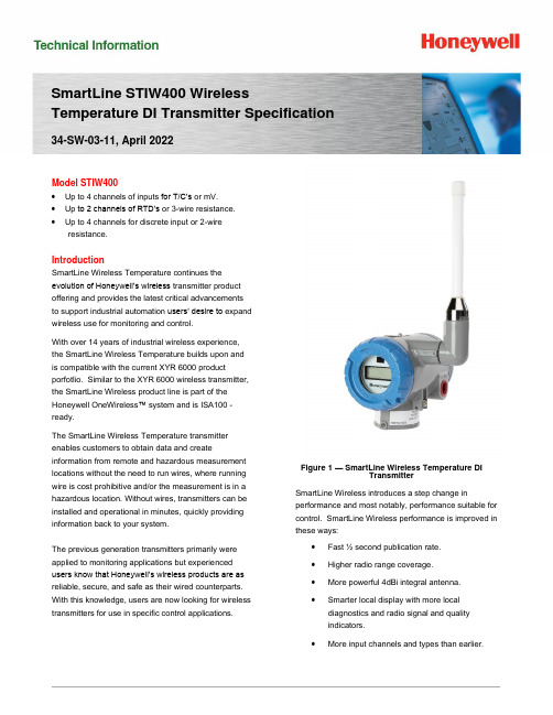
SmartLine STIW400 Wireless Temperature DI Transmitter Specification 34-SW-03-11, April 2022Model STIW400•Up to 4 channels of inputs for T/C’s or mV.•Up to 2 channels of RTD’s or 3-wire resistance.•Up to 4 channels for discrete input or 2-wireresistance.IntroductionSmartLine Wireless Temperature continues theevolution of Honeywell’s wireless transmitter productoffering and provides the latest critical advancementsto support industrial automation users’ desire to expandwireless use for monitoring and control.With over 14 years of industrial wireless experience,the SmartLine Wireless Temperature builds upon andis compatible with the current XYR 6000 productporfotlio. Similar to the XYR 6000 wireless transmitter,the SmartLine Wireless product line is part of theHoneywell OneWireless™ system and is ISA100 -ready.The SmartLine Wireless Temperature transmitterenables customers to obtain data and createinformation from remote and hazardous measurement locations without the need to run wires, where running wire is cost prohibitive and/or the measurement is in a hazardous location. Without wires, transmitters can be installed and operational in minutes, quickly providing information back to your system.The previous generation transmitters primarily were applied to monitoring applications but experienced users know that Honeywell’s wireless products are as reliable, secure, and safe as their wired counterparts. With this knowledge, users are now looking for wireless transmitters for use in specific control applications.Figure 1 — SmartLine Wireless Temperature DITransmitterSmartLine Wireless introduces a step change in performance and most notably, performance suitable for control. SmartLine Wireless performance is improved in these ways:•Fast ½ second publication rate.•Higher radio range coverage.•More powerful 4dBi integral antenna.•Smarter local display with more localdiagnostics and radio signal and qualityindicators.•More input channels and types than earlier.XYR 6000 Wireless Pressure Transmitter Differential Pressure Models 2SmartLine Wireless Temperature retains the following desirable features from the XYR 6000 product offering:•Mesh or non-mesh configuration within each transmitter.•Generic, off-the-shelf lithium ion battery.•Two “D” size batterie s for longer life.•Choice of over-the-air or local provisioning (network security join key).•Over-the-air firmware upgrade capability.•Unique, encrypted provisionng key delivered from the factory.•Remote and integral antenna options.•24 VDC power option.•Publication rates of 1, 5, 10, or 30 seconds, plus new selections of ½ seconds and 1, 15,30, 60 minutes.•Transmitter range (integral antenna) of 1150’ (350 m) under ideal conditions.The STIW400 is a high-performance Temperature transmitter featuring performance over a wide of temperature configurations and applications.The SmartLine family is also fully tested and compliant with Experion® PKS providing the highest level of compatibility assurance and integration capabilities. SmartLine easily meets the most demanding application needs for Temperature measurement applications. SmartLine Wireless FeaturesLocal and over-the-air provisioning capability:All Honeywell wireless devices feature a secure method to join the local wireless network, also known as provisioning. SmartLine Wireless transmitters feature two methods to provision a transmitter onto the network which are eitherby using a handheld device to locally communicate through the IR interface or remotely using the over-the-air function. The over-the-air function is managed by the OneWireless gateway, Wireless Device Manager (WDM). Over-the-air firmware updates:Once joined as a member of your OneWireless network, the WDM can download new transmitter firmware releases to each SmartLine Wireless transmitter over the wireless network. Locating and accessing the transmitter locally is not required thus saving time and keeping your personnel in safe environments.Mesh and non-mesh capability: All SmartLine Wireless transmitters can be configured to operate in either a mesh network or a star (non-mesh) network. The configuration is specific to each wireless transmitter and thus the network can consist of a mixture of meshing and non-meshing devices. Non-meshing is desirable for deterministic communications which is preferred for control. Transmission power setting:To comply with local and regional requirements, SmartLine Wireless transmitters are set at the factory to the maximum transmission power setting allowed for the country of use.Non-proprietary battery:Sourcing lithium thionyl chloride batteries is much simpler since SmartLine Wireless utilizes commercial off-the-shelf batteries. Please see the list of approved battery manufacturers later in this specification. Batteries are housed in an IS-approved battery compartment making battery changes safe and easy. Backward compatibility:SmartLine Wireless transmitters can join existing OneWireless networks and interoperate with existing XYR 6000 wireless transmitters or otherISA100 Wireless compliant transmitters or networks.OneWireless Network FeaturesThe core of the Honeywell wireless solution is the OneWireless Network which consists a gateway, access point(s), and field routers.The Wireless Device Manager (WDM) serves as the gateway function and in this role, manages the communication from the wireless field devices to the process control application. Typically, the WDM connects logically to the process control network (Level 2 or wireless DMZ). As the wireless network manager, the WDM provides easy access to the entire wireless network through a browser-based user interface. The Honeywell WDM can manage devices communicating over theISA100 Wireless protocol and the Wireless HART protocol.The ability to deploy redundant WDMs improves the reliability ensuring no loss of process data which is a requirement for control applications.The Field Device Access Point (FDAP) serves in two roles in the OneWireless network infrastructure, which are: 1) access point, and 2) field router. As an access point, the FDAP directly connects to the WDM via Ethernet LAN cable. More than one access point is permitted and, when more than one is present, it ensures dual path for communications into the WDM from the field devices. As a field router, the FDAP located in the field would communicate to the FDAP acting as an access point. Using the FDAP as a router is more efficient than using field devices as routers since FDAPs are line powered devices whereas field devices are typically battery powered, and the FDAP offers greater range. The meshing capability of FDAPs allows flexibility in the setup of the wireless network to fit the requirements for wireless network performance, in terms of reliable communications, performance, and future growth. The choice of non-meshing network may be desirable for reduced communication latencies with a FDAP serving as a field router.Wireless Specifications*Actual range will vary depending on antennas, cables and site topography.SpecificationsOperating Conditions1 The Ambient Limits shown are for Ordinary Non-Hazardous locations only. Refer to the Hazardous Locations Approvals section for the Ambient Limits when installed in Hazardous Locations.Remote Antenna CablesRemote Antennas8 dBi Omnidirectional Antenna14 dBi Directional AntennaPerformance SpecificationsPerformance under Rated Conditions** Field Calibration available for increased accuracy applications.** Performance specifications are based on reference conditions of 25°C (77°F), 10 to 55% RH. *** Default values; user configurable.Physical Specifications1 Add 8.0 pounds (3.6 Kg) to any model equipped with the stainless steel housing option (Model Selection Guide Table IV selection M or N).STIW400 ISA100.11a Compliant InputsAny combination of sensor type inputs is allowed. The input channels can be configured for the following input types by using the OneWireless User Interface with the corresponding device descriptor file:Selecting any RTD / 3-Wire Ohm Resistance input on Channel 1 and on Channel 3 renders Channel 2's and Channel 4’s input terminals unavailable.The transmitter measures the analog signal from temperature sensors, discrete inputs, millivolt values or ohm values and transmits a digital output signal proportional to the measured value for direct digital communications with systems.The discrete input channels support voltage-free floating contacts. Maximum ON contact resistance is 200 ohms. Minimum OFF contact resistance is 300 ohms. Discrete Input threshold values are user configurable.The Process Variable (PV) is available for monitoring and alarm purposes. The cold junction temperature is also available for monitoring. Available PV update rates are 1, 5, 10, or 30 seconds, plus new selections of ½ sec (Refer User Manual for applicable conditions) and 1, 15, 30, 60 minutes and are set using the Wireless Builder. Slower update rates extend battery life.Input Types and RangesSTIW400 TEMPERATURE TRANSMITTER CONNECTIONST/C or mV or DI or 2 Wire ResistancePV1PV2PV3PV43 Wire RTD or ResistancePV1PV33 Wire RTD or ResistancePV1PV3PV4T/C or mV or DI or 2 Wire ResistanceMounting and DimensionsReference Dimensions:Figure 2 — Examples of typical mounting positionsFigure 3 — Examples of typical mounting positionsFigure 4 – STIW400 Informational and dimensional drawingFigure 5 — Typical mounting dimensions for STIW400Figure 6 — Typical mounting dimensions for STIW400Hazardous Locations ApprovalsRefer to control drawing 50136129, in the user manual #34-SW-25-04, for intrinsically safe installation details.Transmitter Options(indicated selection code is shown)ISA100 Wireless Release Selections (A or B)OneWireless R2xx represents the previous releases whereas R3xx is the current release. A OneWireless system with R3xx firmware can host R2xx and R3xx devices. Please select the option to match the targeted OneWireless system.Remote Antenna and Cables (M or D)The user can select one of the optional remote antennas listed. The selection of the antenna option automatically includes the remote antenna adapter.To complete the option selection, one of the remote antenna cables (1, 2, or 3) must also be selected.Lightning (Surge) Diverter and Cables (1, 2, or 3)The lightning surge diverter options includes the surge diverter and cable. The diverter features Type N connections (female) on both ends. The remote antenna adapter is not included.Remote Antenna Adapter (A)This option provides an adapter to be inserted into the opening where the integral antenna normally connects. The adapter is designed to connect to a remote antenna that the user supplies. It features a female Type N connection.Destination Country (CA, EU, or US)This selection sets the transmission power at the factory to comply with the installation country location.Mounting Brackets (1, 3, 5, or 7)The angle mounting bracket is available in either zinc-plated carbon steel or 316 stainless steel and is suitable for horizontal or vertical mounting on a two-inch (50 millimeter) pipe, as well as wall mounting.An additional flat mounting bracket is also available in carbon steel and 316 stainless steel for two-inch (50 millimeter) pipe mounting.Tagging (Option 1 or 2)The choice of 1 or 2 stainless steel wired-on tags is available. Each tag can accommodate additional data of up to 4 lines of 28 characters. The number of characters includes spaces.Note that the standard nameplate on the meter body contains the serial number and body-related data.Model Selection GuideModel Selection Guides are subject to change and are inserted into the specifications as guidance only.For more informationTo learn more about SmartLine Transmitters, visit Or contact your Honeywell Account ManagerProcess Solutions Honeywell1250 W Sam Houston Pkwy S Houston, USA, TX 77042Honeywell Control Systems LtdHoneywell House, Skimped Hill Lane Bracknell, England, RG12 1EB34-SW-03-11 April 2022©2022 Honeywell International Inc.Shanghai City Centre, 100 Jungi Road Shanghai, China 20061Sales and ServiceFor application assistance, current specifications, ordering, pricing, and name of the nearest Authorized Distributor, contact one of the offices below.ASIA PACIFICHoneywell Process Solutions, Phone: + 800 12026455 or +44 (0) 1202645583 (TAC) hfs-tac-*********************AustraliaHoneywell LimitedPhone: +(61) 7-3846 1255 FAX: +(61) 7-3840 6481 Toll Free 1300-36-39-36 Toll Free Fax: 1300-36-04-70China – PRC - Shanghai Honeywell China Inc.Phone: (86-21) 5257-4568 Fax: (86-21) 6237-2826SingaporeHoneywell Pte Ltd.Phone: +(65) 6580 3278 Fax: +(65) 6445-3033South KoreaHoneywell Korea Co Ltd Phone: +(822) 799 6114 Fax: +(822) 792 9015EMEAHoneywell Process Solutions, Phone: + 800 12026455 or +44 (0) 1202645583Email: (Sales)*************************** or (TAC)*****************************AMERICASHoneywell Process Solutions, Phone: (TAC) (800) 423-9883 or (215) 641-3610(Sales) 1-800-343-0228Email: (Sales)*************************** or (TAC)*****************************。
VM368UR 说明书
功能特征l超薄迷你时尚设计,高级铝合金金属外壳,纳米镀膜玻璃镜片。
l MP3 格式高保真录音功能:内置麦克风(外录)、线录,并可调压缩率。
l超强超长超清晰录音(128M:36 小时/64M:18 小时)。
l多种音源直录(含 CD、VCD、 DVD、 MD、收音机、电视等)。
l声控录音,电话通话内容录音,录音监听功能。
l MP3 音乐播放功能。
l内置高保真扬声器。
l菜单选择控制,A-B循环复读功能。
l六种播放模式(随机播放、全部播放、单曲循环、全部循环、简介播放)。
l六种音效模式选择(FLAT、POP、JAZZ、ROCK、CLAS、 BASS)。
l二种语言选择(简体中文、英文)。
l点阵 LCD 显示, EL背光(可调背光时间和对比度)。
l删除功能,按键锁定功能。
l电池电量指示,自动保护功能。
l可作 U 盘存储文件, WindowsME 以上无需驱动程序,即插即用。
l使用一节 7号电池供电,超长时间播放。
l外型尺寸(不包括突出部分): 100x30x14mm注意事项l为了保持良好性能,请避免在下列场所放置或使用本机。
1. 浴室或其他受潮的地方。
2. 阳光暴晒或靠近加热设备等高温环境下。
3. 温度过低的地方。
4. 多尘的地方。
l请勿自行对本机进行拆修或变更。
l对电池进行短路、拆开或加热、投入火中,将导致电池漏液、发热、破裂,并可能引起火 灾。
l长期不使用本机时,请取出电池,避免电池漏液腐蚀机器内部零件。
l避免摔落或强烈碰撞本机,请勿过分用力按压液晶显示屏,否则可能导致液晶屏损坏或显 示异常。
l请选择合适音量,使用耳机时不宜过大音量若感到耳鸣,请调小音量或停止使用。
l对于非法使用本机所引起的纠纷或因维修及使用中信息丢失或损坏,本公司概不负责,请 用户遵照说明书进行规范操作。
l本公司保留改进产品的权利,产品规格及设计如有变更,恕不另行通知!目录外观图及各部分名称......................................................电池供电..............................................................按键功能及操作说明..........................................................一、开机/关机/播放/暂停/停 止...........................................................二、音量调节................................................................三、模式切换................................................................四、线入录音................................................................五、话筒录音................................................................六、文件删除...................................................................七、锁定按键...................................................................八、菜单操作说明.................................................................九、调节显示屏对比度.............................................................十、设置背光时间 .........................................................十一、选择语言................................................................十二、查看内存空间............................................................... 十三、电话录音.............. .................................................. 连接电脑....................................................................疑难解答.....................................................................规格参数.....................................................................外观图及各部分名称1、 挂绳孔2、PHONE 耳机插孔3、LINE IN 线路输入插孔4、 内置麦克风5、 液晶显示屏6、REC/STOP/A-B 录音/录音停止键/A-B复读键7、MODE/REP 模式/重复方式选择键8、PLAY/PAUSE/STOP 开机/关机/播放/播放暂停/播放停止键9、 电池盖10、USB USB接口11、HOLD 锁定键12、VOL- 音量减少键13、VOL+ 音量增加键14、 /MENU/EQ/DEL 前进/后退/菜单/音效选择/删除等多功能组合键15、 喇叭电池供电本机使用一节“AAA” 七号碱性电池l安装电池推开电池盖,按负极朝内,正极朝外方向装入一节电池,关上电池盖,如图:l电量指示电量充足 稍有不足 更换新电池 自动关机l电量较低时请及时更换电池,否则会自动关机,影响当前使用。
MAX线机LM精编MA键盘按键功能说明书精编版

M A X线机L M精编M A键盘按键功能说明书公司内部编号:(GOOD-TMMT-MMUT-UUPTY-UUYY-DTTI-M A X线号机L M-370A/L M-380A键盘按键功能说明书日本MAX公司LM-380A新一代微电脑线号印字机:是针对电力成套及其他需要布线行业制作套管、标签标示的专业设备。
本公司本着“品质优良、价格合理、服务及时”的经营原则。
并不断追求更高的企业品质以回馈各界的支持与厚爱!公司所有产品均为终身维护,一年免费保修。
LM-380A微电脑高速套管打印机一套标准配置机器一台,手提箱一个,专用电源一个,LM-IR310B色带一盘,LM-IR300B色带卡匣1个.中英文说明书各一本.LM-380A微电脑高速套管打印机主要功能:MAX LETATWIN LM-380A电脑线号印字机是针对专业人士制作套管及标签标示所全新设计(中文化的标示,操作更简单轻松)1、高速打印:LM-380A拥有快速的打印功能,可提供每秒25m的打印速度,能够在一分钟内高速打印出35个20mm长的套管。
2、最大打印长度:LM-380A一次最大打印套管长度可达20M(LM-370A为6M)、标签贴纸一次最大打印长度可达5M(LM-370A为1M)3、LM-380A拥有强大的内存容量:内建大容量记忆体,最大可容纳40000个字元。
4、功能强大的PC专用软件:LM-380A可以使用附赠的专用软件编辑,搭配CF CARD储存大量的标示文字资料,操作更能让您随心所欲。
5、切刀深度调整:LM-380A拥有独特的切刀调整功能,当半切刀位置太深或太浅时,可以通过调整半切深度拉杆来调整切刀深度。
6、全中文输入,中文化键盘及界面(除了英文字母、数字和特殊符号,中文字也可以利用键盘直接拼音输入。
7、高质量打印材料:可打印0.5mm、1.0mm、1.5mm、2.0mm、2.5mm、4.0mm、6.0mm的套管和热收缩套管,打印速度快,不掉色。
winmax 资料

iMax(Worldwide Interoperability for Microwave Access),即全球微波互联接入。
WiMAX的另一个名字是802.16。
WiMAX是一项新兴的宽带无线接入技术,能提供面向互联网的高速连接,数据传输距离最远可达50km。
WiMAX还具有QoS 保障、传输速率高、业务丰富多样等优点。
WiMAX的技术起点较高,采用了代表未来通信技术发展方向的OFDM/OFDMA、AAS、MIMO等先进技术,随着技术标准的发展,WiMAX逐步实现宽带业务的移动化,而3G 则实现移动业务的宽带化,两种网络的融合程度会越来越高。
目录简介一、工作原理二、主要构成三、相关区别四、技术特点五、优缺点六、具体分类七、发展状况简介一、工作原理二、主要构成三、相关区别四、技术特点五、优缺点六、具体分类七、发展状况∙八、发展部署∙九、应用前景∙十、解决方案∙十一、目前状况∙十二、技术竞争∙十三、标准进展∙十四、产业发展展开编辑本段简介WiMAX又称为802·16无线城域网,是又一种为企业和家庭用户提供“最后一英里”的宽带无线连接方案。
因在数据通信领域的高覆盖范围(可以覆盖25~30英里的范围),以及对3G可能构成的威胁,使WiMAX在最近一段时间备受业界关注。
该技术以IEEE 802.16的系列宽频无线标准为基础。
一如当年对提升802.11使用率有功的Wi-Fi 联盟,WiMAX 也成立了论坛,将提高大众对宽频潜力的认识,并力促供应商解决设备兼容问题,借此加速WiMAX 技术的使用率,让WiMAX 技术成为业界使用IEEE 802.16 系列宽频无线设备的标准。
虽然WiMAX 无法另辟新的市场﹙目前市面已有多种宽频无在线网方式﹚,但是有助于统一技术的规范,有了标准化的规范,就可以以量制价,降低成本,提高市场增长率。
短期而言﹙2004年﹚,WiMAX 论坛将在年底之前,着手开发认证流程,为最后一步的产品测试预作准备。
MAXIM MAX3680 MAX3680A 说明书

_________________General DescriptionThe M AX3680/M AX3680A deserializer is ideal for con-verting 622Mbps serial data to 8-bit-wide, 77Mbps par-allel data in ATM and SDH/SONET applications.Operating from a single +3.3V supply, this device accepts PECL serial clock and data inputs, and deliv-ers TTL clock and data outputs. The MAX3680 also pro-vides a TTL synchronization input that enables data realignment and reframing.The MAX3680/MAX3680A is available in the extended-industrial temperature range (-40°C to +85°C), in a 28-pin SSOP package.__________________________Applications622Mbps SDH/SONET Transmission Systems 622Mbps ATM/SONET Access Nodes Add/Drop Multiplexers Digital Cross-Connects______________________________Features♦Single +3.3V Supply♦622Mbps Serial to 77Mbps Parallel Conversion ♦165mW Power♦Synchronization Input for Data Realignment and Reframing (MAX3680)♦Differential 3.3V PECL Clock and Data Inputs ♦TTL Data OutputsMAX3680/MAX3680A+3.3V , 622Mbps, SDH/SONET 1:8 Deserializer with TTL Outputs________________________________________________________________Maxim Integrated Products 1___________________________________________________________________Typical Operating CircuitPin Configuration appears at end of data sheet.For pricing, delivery, and ordering information,please contact Maxim/Dallas Direct!at 1-888-629-4642, or visit Maxim’s website at .+Denotes lead-free package.M A X 3680/M A X 3680A+3.3V , 622Mbps, SDH/SONET1:8 Deserializer with TTL Outputs 2_______________________________________________________________________________________ABSOLUTE MAXIMUM RATINGSDC ELECTRICAL CHARACTERISTICS(V CC = +3.0V to +3.6V, T A = -40°C to +85°C, unless otherwise noted. Typical values are at V CC = +3.3V, T A = +25°C.)Stresses beyond those listed under “Absolute Maximum Ratings” may cause permanent damage to the device. These are stress ratings only, and functional operation of the device at these or any other conditions beyond those indicated in the operational sections of the specifications is not implied. Exposure to absolute maximum rating conditions for extended periods may affect device reliability.Note 2:AC characteristics guaranteed by design and characterization.Note 1:The SYNC input is available only on the MAX3680.Terminal Voltage (with respect to GND)V CC ........................................................................-0.5V to +5V PECL Inputs (SD+/-, SCLK+/-)................-0.5V to (V CC + 0.5V)TTL Input (SYNC)....................................-0.5V to (V CC + 0.5V)TTL Outputs (PCLK, PD_)........................-0.5V to (V CC + 0.5V)Continuous Power Dissipation (T A = +85°C)SSOP (derate 9.52mW/°C above +85°C).....................619mW Operating Temperature Range ...........................-40°C to +85°C Storage Temperature Range.............................-65°C to +160°C Lead Temperature (soldering, 10s).................................+300°CAC ELECTRICAL CHARACTERISTICS(V CC = +3.0V to +3.6V, T A = +25°C, unless otherwise noted.) (Note 2)MAX3680/MAX3680A+3.3V , 622Mbps, SDH/SONET 1:8 Deserializer with TTL Outputs_______________________________________________________________________________________31.20MAXIMUM SERIAL-CLOCK FREQUENCYvs. TEMPERATURE00 S E R I A L C L O C K F R E Q U E N C Y (G H z )-251.125501.00.90.875100TEMPERATURE (°C)1.3-50360SERIAL DATA SETUP TIMEvs. TEMPERATURE00 S E R I A L D A T A -S E T U P T I M E (p s )-25320255028024020075100TEMPERATURE (°C)400-50-160SERIAL DATA HOLD TIME vs. TEMPERATURE00 S E R I A L D A T A -H O L D T I M E (p s )-25-2202550-280-340-40075100TEMPERATURE (°C)-100-5060500SUPPLY CURRENT vs. TEMPERATURE00 S U PP L Y C U R R E N T (m A )-25402550301020075100TEMPERATURE (°C)70-50__________________________________________Typical Operating Characteristics(V CC = +3.0V to +3.6V, unless otherwise noted.)M A X 3680/M A X 3680A+3.3V , 622Mbps, SDH/SONET1:8 Deserializer with TTL Outputs 4_______________________________________________________________________________________Figure 1. Functional DiagramMAX3680/MAX3680A+3.3V , 622Mbps, SDH/SONET 1:8 Deserializer with TTL Outputs_______________________________________________________________________________________5Figure 2a. Functional Timing Diagram—Normal OperationM A X 3680/M A X 3680A+3.3V , 622Mbps, SDH/SONET1:8 Deserializer with TTL Outputs 6_______________________________________________________________________________________Figure 2b. Functional Timing Diagram—SYNC Operation (MAX3680)Figure 3. Timing ParametersMAX3680/MAX3680A+3.3V , 622Mbps, SDH/SONET 1:8 Deserializer with TTL Outputs_______________________________________________________________________________________7PECL InputsThe serial data and clock PECL inputs (SD+, SD-,SCLK+, SCLK-) require 50Ωtermination to (V CC - 2V)when interfacing with a PECL source (see Alternative PECL Input Termination ).Applications InformationAlternative PECL Input TerminationFigure 4 shows alternative PECL input-termination methods. Use Thevenin-equivalent termination when a (V CC - 2V) termination voltage is not available. If AC coupling is necessary, such as when interfacing with an ECL-output device, use the ECL AC-coupling termi-nation.Layout TechniquesFor best performance, use good high-frequency layout techniques. Filter voltage supplies and keep ground connections short. Use multiple vias where possible.Also, use controlled impedance transmission lines to interface with the MAX3680 data inputs.Figure 4. Alternative PECL Input TerminationPin ConfigurationChip InformationTRANSISTOR COUNT: 1346________________________________________________________Package InformationM A X 3680/M A X 3680A+3.3V , 622Mbps, SDH/SONET1:8 Deserializer with TTL Outputs Revision HistoryRev 0;3/97:Initial MAX3680 release.Rev 1;11/00:Changed t CLK-Q max from 1300ps to 2000ps (page 2); replaced TOC3 (page 3).Rev 2;7/04:Added lead-free package to Ordering Information table (page 1).Rev 3;3/07:Added MAX3680A (pages 1, 2, 4, 6, 7).M axim cannot assume responsibility for use of any circuitry other than circuitry entirely embodied in a M axim product. No circuit patent licenses are implied. Maxim reserves the right to change the circuitry and specifications without notice at any time.8_____________________Maxim Integrated Products, 120 San Gabriel Drive, Sunnyvale, CA 94086 408-737-7600©2007 Maxim Integrated Productsis a registered trademark of Maxim Integrated Products, Inc.。
FDMS3686S;中文规格书,Datasheet资料

FDMS3686S PowerTrench ® Power Stage©2012 Fairchild Semiconductor CorporationFDMS3686S Rev.C11January 2012FDMS3686SPowerTrench ® Power StageAsymmetric Dual N-Channel MOSFETFeaturesQ1: N-ChannelMax r DS(on) = 8 m Ω at V GS = 10 V, I D = 13 A Max r DS(on) = 11 m Ω at V GS = 4.5 V, I D = 11 A Q2: N-ChannelMax r DS(on) = 2.8 m Ω at V GS = 10 V, I D = 23 A Max r DS(on) = 3.8 m Ω at V GS = 4.5 V, I D = 21 ALow inductance packaging shortens rise/fall times, resulting in lower switching losses MOSFET integration enables optimum layout for lower circuit inductance and reduced switch node ringing RoHS CompliantGeneral DescriptionThis device includes two specialized N-Channel MOSFETs in a dual PQFN package. The switch node has been internally connected to enable easy placement and routing of synchronous buck converters. The control MOSFET (Q1) and synchronous SyncFET (Q2) have been designed to provide optimal power efficiency.ApplicationsComputing CommunicationsGeneral Purpose Point of Load Notebook VCORE MOSFET Maximum Ratings T A = 25 °C unless otherwise notedThermal CharacteristicsPackage Marking and Ordering InformationSymbol ParameterQ1Q2Units V DS Drain to Source Voltage3030V V GS Gate to Source Voltage (Note 3)±20±20VI D Drain Current -Continuous (Package limited) T C = 25 °C 3055A-Continuous (Silicon limited) T C = 25 °C 54123 -Continuous T A = 25 °C 131a 231b -Pulsed40100E AS Single Pulse Avalanche Energy 404604mJ P D Power Dissipation for Single Operation T A = 25 °C 2.21a2.51bW Power Dissipation for Single Operation T A = 25 °C 1.01c 1.01dT J , T STGOperating and Storage Junction Temperature Range-55 to +150°CR θJA Thermal Resistance, Junction to Ambient 571a 501b °C/WR θJA Thermal Resistance, Junction to Ambient 1251c 1201d R θJCThermal Resistance, Junction to Case3.52.0Device MarkingDevice Package Reel Size Tape Width Quantity 22CA F10CCFDMS3686SPower 5613 ”12 mm3000 unitsPower 56G1D1D1D1G2S2S2S2D1PHASE (S1/D2)TopBottom® Power Stage©2012 Fairchild Semiconductor Corporation FDMS3686S Rev.C12On CharacteristicsDynamic CharacteristicsSwitching CharacteristicsForwadQ2100nAV GS(th)Gate to Source Threshold Voltage V GS = V DS , I D = 250 μA V GS = V DS , I D = 1 mAQ1Q2 1.11.121.5 2.73.0VΔV GS(th) ΔT JGate to Source Threshold Voltage Temperature CoefficientI D = 250 μA, referenced to 25 °C I D = 10 mA, referenced to 25 °C Q1Q2 -6-4 mV/°C r DS(on)Drain to Source On Resistance V GS = 10 V, I D = 13 A V GS = 4.5 V, I D = 11 AV GS = 10 V, I D = 13 A , T J = 125 °C Q15.88.57.881110.8m ΩV GS = 10 V, I D = 23 A V GS = 4.5 V, I D = 21 AV GS = 10 V, I D = 23 A , T J = 125 °C Q2 2.23.03.1 2.83.84.0g FSForward Transconductance V DS = 5 V, I D = 13 A V DS = 5 V, I D = 23 AQ1Q261124SC iss Input Capacitance Q1:V DS = 15 V, V GS = 0 V, f = 1 MHZ Q2:V DS = 15 V, V GS = 0 V, f = 1 MHZQ1Q2 1340182017852420pF C oss Output CapacitanceQ1Q2 485725645965pF C rss Reverse Transfer Capacitance Q1Q2 538680130pF R gGate ResistanceQ1Q20.20.20.60.923Ωt d(on)Turn-On Delay Time Q1:V DD = 15 V, I D = 13 A, R GEN = 6 ΩQ2:V DD = 15 V, I D = 23 A, R GEN = 6 ΩQ1Q2 8.291618ns t r Rise TimeQ1Q2 2.541010ns t d(off)Turn-Off Delay Time Q1Q2 20233236ns t f Fall TimeQ1Q2 2.231010ns Q g Total Gate Charge V GS = 0 V to 10 V Q1V DD = 15 V,I D = 13 AQ2V DD = 15 V, I D = 23 AQ1Q221272937nC Q g Total Gate ChargeV GS = 0 V to 4.5 V Q1Q210131418nC Q gs Gate to Source Gate Charge Q1Q2 3.94.6nC Q gdGate to Drain “Miller” ChargeQ1Q23.13.7nC® Power Stage©2012 Fairchild Semiconductor Corporation FDMS3686S Rev.C13F Q22336Notes:1. R qJA is determined with the device mounted on a 1 in 2 pad 2 oz copper pad on a 1.5 x 1.5 in. board of FR-4 material. R qJC is guaranteed by design while R qCA is determined by the user's board design.2. Pulse Test: Pulse Width < 300 ms, Duty cycle < 2.0%.3. As an N-ch device, the negative Vgs rating is for low duty cycle pulse ocurrence only. No continuous rating is implied.4. Q1: E AS of 40 mJ is based on starting T J = 25 o C; N-ch: L = 1 mH, I AS = 9 A, V DD = 27 V, V GS = 10 V. 100% test at L= 0.3 mH, I AS = 14 A. Q2: E AS of 60 mJ is based on starting T J = 25 o C; N-ch: L = 1 mH, I AS = 11 A, V DD = 27 V, V GS = 10 V. 100% test at L= 0.3 mH, I AS = 17 A.a. 57 °C/W when mounted on a 1 in 2 pad of 2 oz copperc. 125 °C/W when mounted on a minimum pad of 2 oz copperb. 50 °C/W when mounted on a 1 in 2 pad of 2 oz copperd. 120 °C/W when mounted on a minimum pad of 2 oz copperGDF DS SF SS GDF DS SF SS GDF DS SF SS GDF DS SF SSPower StageFDMS3686S Rev.C1Power Stage5FDMS3686S Rev.C1Power Stage6FDMS3686S Rev.C1Power StageFDMS3686S Rev.C1® Power StageFDMS3686S Rev.C18Power Stage9FDMS3686S Rev.C1®Power Stage10FDMS3686S Rev.C1分销商库存信息: FAIRCHILD FDMS3686S。
M-MAX 频率转换器系列产品信息说明书
MMX34AA012F0-0MMX34AA4D3F0-0MMX12AA3D7F0-0MMX12AA9D6F0-0MMX34AA1D3F0-0 MMX12AA1D7F0-0MMX12AA2D4F0-0MMX12AA4D8F0-0MMX34AA1D9F0-0MMX34AA2D4F0-0Operating comfort redefined Frequency Inverters M-MAXProduct InformationFrequency Inverter M-MAXM-MAX Frequency InverterSystem FeaturesThe M-MAX series frequency inverters allow drives to be adapted easily to customer requirements. With a compact design for assigned motor ratings from 0.25 kW to 5.5 kW, M-MAX can offer maximum flexibility. M-MAX also demonstrates how a high level of functionality can be implemented in a simple and user-friendly design. The small and compact book format design also allows a space saving installation. M-MAX is provided with an integrated RFI filter (EMC) and a flexible interface for solving important machine building requirements, for example, the optimization of production and manufacturing processes. It reliably ensures the required motion sequences of the drive motor and thus contributes to operational safety.M-MAX – the “energy optimizer“M-MAX frequency inverters provide an economical solution for several processes in pumping applications. The integrated PI controller and extensive motor-protective functions ensure a high level of operational reliability and allow significant energy savings in the connected process. The lacquered control boards also allow use in highly humid and aggres-sive environments, such as in a sewage treatment plant. The optional MMX-IP21-FS... accessory enables the degree of protection of the M-MAX to be increased to IP21.M-MAX – the “safe operator“Good climatic conditions as well as safe operation in the event of fire (fume removal) are demanding tasks for frequency controlled ventilation systems in buildings. With its internal protective circuits and the automatic restart option (e.g. after a momentary power failure), as well as automatics ynchronization with the running motor (flying restart circuit), the frequency inverters of the M-MAX series ensure the safe operation of fans in air conditioning and smoke control systems.M-MAX – for “dynamic precision“The compact design of the M-MAX saves valuable mounting space in machine building since the RFI filter and the brake chopper are already integrated. Shielded control and motor cable can also be connected with EMC compliance directly to the frequency inverter. The maximum permissible ambient temperature of +50 °C during operation with continuouscurrent and with full overload withstand capability also meets machine building requirements. The performance of the sensorless vector control ensures also a high speed accuracy; even with load deviations and low motor speeds.MMX-COM-PC – the “in-line communicator“The MMX-COM-PC communication module that can be plugged onto the front provides the following without a mains voltage on the frequency inverter (internal battery):Upload and download of all parameters,• Direct link to a PC via USB interface (parameter • assignment),Copying of parameters for series machines or when • exchanging devices.This communication module considerably increases datas ecurity and reduces the time required for commissioning and maintenance.FeaturesIntegrated RFI filter (EMC: C2 and C3 to/EN61800-3)• Dynamic motor control with sensorless vector control or V/f • control (selectable)Integrated keypad and display unit• Electronic reference value potentiometer • Fixed frequencies • PI controller• Integrated brake unit (with MMX34 in sizes 2 and 3)• 6 digital control inputs (24 V DC)• 1 digital output (transistor, 24 V DC, 50 mA)• 2 analog inputs (0...+10 V DC and 0/4.20 mA)• 1 output analog (0/4...20 mA)• Serial interface (RS485 / Modbus RTU)• 2 relays (1x NO, 1x changeover, 230 V AC, 2 A)• International standards (CE, UL, cUL, c-Tick)• Application examplesSpeed control of asynchronous three-phase motors up to • 5.5 kW (400 V)Pump and fan applications in buildings and industrial areas • with quadratic and linear load characteristics.The high speed accuracy (sensorless) allows a whole range • of possible applications in the textile, paper and printing industry, as well as with finishing machines in the metal industry.The compact design with integrated EMC filter offers• maximum flexibility in machine building and saves valuable mounting space.The twofold startup torque and 1.5 overload torque allows • the implementation of applications with demanding speed and torque requirements.Frequency inverters - simple and straightforwardDisplay unitFunction keysSTARTMotor start via keypad(function must be activated)STOPMotor stop via keypad• Acknowledges the display fault message (Reset)• Activates the Startup Wizard (press for 5 s)• OKActivates the selected parameter • Confirm the set value• Parameter group selection (submenu)• BACK/RESETBack in menu. Exit edit mode and acknowledge error messages (reset).LOC/REMMove between different control levels (keypad – control terminals – fieldbus)UP/DOWNMenu level selection in the display unit (• Y )Change in the parameter groups and • parameter listsIncrease and reduce parameter values • Increase and reduce reference value • (electronic motor potentiometer)Status symbols (D ):READY = Ready to start RUN = Operational STOP = S top, Stop command active ALARM = Alarm message active FAULT = D rive was stopped due to an error message Menu level (Y ):REF = Reference value entry MON = Monitor operating data PAR = Parameters FLT = Fault memory (Fault)Control commands (C ):FWD = Forward run REV = Reverse run I/O = Via control terminals (Input/Output)KEYPAD = Via the keypad BUS = Via fieldbus (interface)Backlit liquid crystal display (LCD)Technical data (extract)*) Rated motor current for normal four-pole internal and surface cooled asynchronous three-phase motors (1500 rpm). Operating dataAccessoriesEaton’s electrical business is a global leader in electrical control, power distribution,uninterruptible power supply and industrial automation products and services.Eaton’s global electrical brands, including Cutler-Hammer ®, MGE Office Protection Systems™, Powerware ®, Holec ®, MEM ®,Santak and Moeller, provide customer-driven PowerChain Management® solutions to serve the power system needs of the industrial,institutional, government, utility, commercial,residential, IT, mission critical and OEM markets 4 *p a t p k a #y .x y c m *Moeller addresses worldwide:/address E-Mail: info @ Internet: w Issued by Moeller GmbH Hein-Moeller-Str. 7-11D-53115 Bonn© 2008 by Moeller GmbH Subject to alterations W8230-7606en ip 01/09Printed in Germany (01/09)Article No.: 121384MMX34AA9D0F0-0MMX34AA5D6F0-0MMX34AA7D6F0-0MMX12AA2D8F0-0MMX34AA012F0-0MMX34AA4D3F0-0MMX12AA3D7F0-0MMX12AA9D6F0-0MMX34AA1D3F0-0 MMX12AA1D7F0-0MMX12AA2D4F0-0MMX12AA4D8F0-0MMX34AA1D9F0-0MMX34AA2D4F0-0。
Lexmark X264dn、X363dn、 X364dn 和 X364dw 说明书

加载纸张和特殊介质.............................................................................39
设置“纸张尺寸”和“纸张类型”............................................................................................39 配置 Universal 纸张设置...........................................................................................................39 避免卡纸...................................................................................................................................40 加载进纸匣................................................................................................................................41 使用多功能或手动进纸器..........................................................................................................45 纸张容量...................................................................................................................................50 进纸匣连接和解除连接..............................................................................................................51