Measurement of Workload for Voice User Interface Systems
Fluke Calibration 2271A工业压力计ibrator说明书
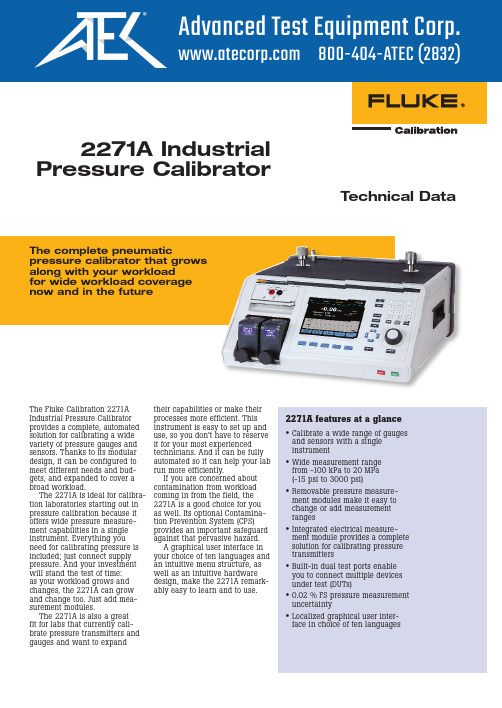
2271A Industrial Pressure CalibratorTechnical DataThe complete pneumaticpressure calibrator that grows along with your workload for wide workload coverage now and in the futureThe Fluke Calibration 2271A Industrial Pressure Calibrator provides a complete, automated solution for calibrating a wide variety of pressure gauges and sensors. Thanks to its modular design, it can be configured to meet different needs and bud-gets, and expanded to cover a broad workload.The 2271A is ideal for calibra-tion laboratories starting out in pressure calibration because it offers wide pressure measure-ment capabilities in a single instrument. Everything you need for calibrating pressure is included; just connect supply pressure. And your investment will stand the test of time: as your workload grows and changes, the 2271A can grow and change too. Just add mea-surement modules.The 2271A is also a great fit for labs that currently cali-brate pressure transmitters and gauges and want to expand2271A features at a glance•Calibrate a wide range of gauges and sensors with a single instrument•Wide measurement range from -100 kPa to 20 MPa (-15 psi to 3000 psi)•Removable pressure measure-ment modules make it easy to change or add measurement ranges•Integrated electrical measure-ment module provides a complete solution for calibrating pressure transmitters•Built-in dual test ports enable you to connect multiple devices under test (DUTs)•0.02 % FS pressure measurement uncertainty•Localized graphical user inter-face in choice of ten languagestheir capabilities or make their processes more efficient. This instrument is easy to set up and use, so you don’t have to reserve it for your most experienced technicians. And it can be fully automated so it can help your lab run more efficiently.If you are concerned about contamination from workload coming in from the field, the 2271A is a good choice for you as well. Its optional Contamina-tion Prevention System (CPS) provides an important safeguard against that pervasive hazard.A graphical user interface in your choice of ten languages and an intuitive menu structure, as well as an intuitive hardware design, make the 2271A remark-ably easy to learn and to use.1T hese external drivers are 24 V dc outputs that operate accessories such as the Contamination Prevention System2U SB port3E thernet connector4R S-232 connector5M aster on/off switch6L ine power fuse AC PWR INPUT Connector7A ll of the pressure connections are madeon the rear panel through this replaceable manifold8G raphical user interface in choice of ten languages features an easy-to-read, intuitive menu structure that lets you access any feature within four button presses or less 9T he large main display enables you to easily view and edit important information10R eal time graph makes it easy to see pressure stability or procedure status11F unction softkeys12P ush the Setpoint button to quickly enter a pressure value to control13P ressure measurement modules snap in and out easily14T est ports provide easy, hand-tightconnection to devices under test15R eference port for applications that require an atmospheric reference16 Handle17M ake minor adjustments to the pressure using the jog wheel; ideal for calibration of analog dial gauges1234567108914151416171112132 Fluke Corporation 2271A Industrial Pressure CalibratorVersatile pressure measurement modules The 2271A uses PM200 Pressure Measurement Modules. These modules use a highly character-ized silicon pressure sensor to provide an economical method of making accurate pressure measurements. The 0.02 % full scale (FS) specification includes the short-term performance of the module (linearity, hysteresis and repeatability) as well asits long-term stability and the uncertainty of the calibration standard. Users can be confi-dent in the PM200 measurement performance.Install up to two pressure modules in the 2271A chassis at one time, mixing and match-ing module ranges to get the combination that best suits your needs. There is no limit to the number of modules that can be used with the system, allowing you to change pressure ranges on the fly to meet your needs. Modules snap in and out quickly and easily through the front of the 2271A; just slide each into a specially-designed track and tighten the knob until you hear it click into place. The click tells you the module is safelyin place; a special anti-torque guard on the knob prevents over-tightening so you never have to wonder if you tightened it too much or not enough. Each module uses an enhanced face-seal design that has been leak tested to pres-sures three times higher than the maximum working pressure. You don’t have to worry about a leak in the system affecting your ability to measure and control pressure.Wide workload coverage for the present and the futureThe 2271A features pres-sure ranges from -100 kPa to20 MPa (-15 psi to 3000 psi), which covers the requirements of a wide range of gauges and sensors. Thanks to its modular design, the 2271A enables you to install two modules with different measurement ranges within the same chassis. You can purchase modules to match your current workload now; later, when your workload changes and grows, you can easily add ranges. This flexibility enables you to maintain your investment in the 2271A for years to come.A built-in electrical measure-ment module (EMM) with HARTcapabilities enables you to per-form closed loop, fully automated calibration on 4-20 mA devices such as smart transmitters, gauges and switches. Just set up the 2271A and then walk away to attend to other tasks.The EMM supplies 24 V dc loop power for measuring mA and V dc. It has a built-in 250 Ohm resistor that can be toggled on or off, eliminating the need to have an external resistor to enable HART communications. The 2271A accuracy specifi-cations are provided in full and supported by a technical note that details its measurement uncertainty so you know exactly what you are getting. This technical note is available for download on the website. As with all Fluke Calibration instruments, these specifications are conservative, complete and dependable.Use the 2271A to perform closed loop, fully automated calibration on4-20 mA devices like this transmitter.Install up to two pressuremodules in the 2271Achassis at one time.3 Fluke Corporation 2271A Industrial Pressure CalibratorDual test ports on top of the 2271A let you easily mount two devices under test.Conveniently located dual test ports and reference portDual test ports on the top of the 2271A let you easily mount two devices under test (DUTs). You can potentially double your throughput without spending time searching for fittings and tees. The vertical test ports let you easily connect analog dial gauges without the need for additional test stands or mani-folds. Two test port types are supported, the standard HC20 or the P3000 test port. Both types of test ports enable you to make hand tight connections to traditional NPT, BSP, or metric pressure fittings. The HC20 test port includes easy grip features and integral support for M20connections, whereas the P3000style test port provides back-wards compatibility for users ofFluke Calibration P3000 dead-weight testers or P5500 pressurecomparators.A reference port is alsolocated on top of the 2271A forapplications that require anatmospheric reference.Safety features protectoperators and instrumentsEach measurement module, aswell as the main chassis, haspressure relief valves to protectthe instrument and its operatorsfrom accidental overpressure.The 2271A has been designedusing Sound Engineering Prac-tices (SEP). With the internalrelief valves, user-settable pres-sure limits, and emergency abortbutton, safety is the highestpriority.Preventing contaminationIf your workload includes devicesthat contain different substanceslike water, oil and gas, youcould be at risk for contamina-tion—something getting into yoursystem that isn’t supposed to bethere. Contamination can cloga calibrator’s valves, wear outits parts, and make it difficult tomaintain pressure. If the con-tamination gets into the sensor,it can actually change the cali-brator’s behavior and throw offyour readings. If contaminationis a concern to you, order theoptional Contamination Preven-tion System (CPS) to help keepthe calibrator’s valves clean andfree from debris.The CPS provides an unprec-edented level of protection bymaintaining uni-directionalflow away from the controller, agravity sump system, and a two-stage filtering system.The Contamination Prevention System helps keep the valves on the 2271A cleanand free from debris.4 Fluke Calibration 2271A Industrial Pressure CalibratorAutomation, support and trainingAutomate with COMPASS®software for improved con-sistency and throughput Fluke Calibration COMPASS for Pressure software is designed specifically for pressure calibra-tion. It enables you to automate the 2271A and run complete pressure calibration sequences on single or multiple devices under test. COMPASS software removes the unknowns often associated with getting auto-mated systems online. The 2271A also features a full remote interface that enables you to use it with custom software or other data acquisition equip-ment. Details about the interface are provided in the 2271A User Manual.CarePlans help you manage cost of ownershipReduce downtime and control your cost of ownership with a CarePlan. Fluke Calibration offers one-year, three-year and five-year Priority Gold CarePlans, which feature an annual stan-dard or accredited calibrationof your 6270A calibrator with guaranteed six-day in-house turnaround, plus free repairs with guaranteed ten-dayin-house repair (includes cali-bration). One-year, three-year, and five-year Silver CarePlans are available for those customers who only want extended war-ranty coverage.A range of training optionsgets you up and runningquicklyWe sponsor pressure and flowcalibration courses in our Phoe-nix, Arizona facility in the UnitedStates. We also host periodicweb seminars at no charge on awide variety of pressure calibra-tion topics. If you need serviceor maintenance training to helpyou maintain your fleet of pres-sure controllers, we can help youthere, too.We’re here to helpFluke Calibration’s testing, repairand calibration services arededicated to filling your needsquickly and at a fair cost whilemaintaining the unmatched levelof quality that is our trademark.Our pressure calibration labo-ratories are accredited by theAmerican Association for Labo-ratory Accreditation (A2LA) forconformance to ISO Guide 17025.We maintain global calibrationand repair facilities to help youkeep your hardware in top work-ing order.Gold CarePlans Silver CarePlansAnnual calibration Extended warranty coveragebeyond original factory warrantyFree repairs with guaranteed Calibration included on repairPre-paid priority freight on return Free product updates performed attime of repairInstrument CarePlanInstrument CarePlanWe sponsor pressure and flow calibration courses inour Phoenix, Arizona facility.5 Fluke Calibration 2271A Industrial Pressure CalibratorSummary specificationsSupply pressure requirementsClean dry air or nitrogen (industrial grade, 99.5 %)Maximum particulate contamination≤ 1.25 micrometer (50 microinches)Maximum moisture content-50 °C dew pointMaximum hydrocarbon content30 ppmInterface / communicationsPrimary remote interfaces Ethernet, RS-232, USBElectrical Measurement Module (EMM)Connection Standard 4 mm jackMaximum 30 V dc w.r.t. chassis groundAux drivers 4 external solenoid drivers24 V dc. 100 % duty cycle when turned, reducing to 40 % shortly after.6 Fluke Calibration 2271A Industrial Pressure CalibratorPressure measurement specificationsNotes•G auge mode modules (PM200-GXXX or PM200-BGXXX) with ranges of 100 kPa (15 psi) or greater will support absolute mode measurement when used with a Barometric Reference Module.•F or temperatures from 15 °C to 18 °C and 28 °C to 35 °C, add 0.003 % FS/°C.•U ncertainty for gauge mode modules assumes routine zeroing. Uncertainty for absolute-mode modules includes 1-year zero stability.This specification can be reduced to 0.05 % FS if the PM200 module is zeroed on a continuing basis to remove the 1-year zero stability component.•I nstrumental measurement uncertainty for gauge mode modules used in absolute mode by addition of a barometric reference module iscalculated as the uncertainty of the gauge mode module plus the uncertainty of the Barometric Reference Module.7 Fluke Calibration 2271A Industrial Pressure Calibrator8 Fluke Corporation 2271A Industrial Pressure CalibratorFluke Calibration PO Box 9090,Everett, WA 98206 U.S.A.Fluke Europe B.V.PO Box 1186, 5602 BD Eindhoven, The NetherlandsWeb access: http://www.flukecal.euFor more information call:In the U.S.A. (877) 355-3225 or Fax (425) 446-5716In Europe/M-East/Africa +31 (0) 40 2675 200 or Fax +31 (0) 40 2675 222 In Canada (800)-36-FLUKE or Fax (905) 890-6866From other countries +1 (425) 446-6110 or Fax +1 (425) 446-5716 Web access: ©2016 Fluke Calibration. Specifications subject to change without notice. Printed in U.S.A. 3/2016 6007367a-enModification of this document is not permitted without written permission from Fluke Calibration.Fluke Calibration. Precision, performance, confidence.™Ordering informationModelsDescription2271A-NPT-HC20Industrial Pressure Calibrator Chassis, NPT Manifold, HC20 Test Port Connections 2271A-NPT-P3K Industrial Pressure Calibrator Chassis, NPT Manifold, P3000 Test Port Connections 2271A-BSP-HC20Industrial Pressure Calibrator Chassis, BSP Manifold, HC20 Test Port Connections 2271A-BSP-P3KIndustrial Pressure Calibrator Chassis, BSP Manifold, P3000 Test Port ConnectionsPressure modulesPlease refer to the summary specifications for details about the pressure measurement modules.Accessories CASE-2271Shipping Case, 2271ACASE-PMM Shipping Case, 3 PMM ModulesPK-2271-NPT-HC20Lines and Fittings Kit, 2271A-NPT-HC20PK-2271-NPT-P3K Lines and Fittings Kit, 2271A-NPT-P3K PK-2271-BSP-HC20Lines and Fittings Kit, 2271A-BSP-HC20PK-2271-BSP-P3K Lines and Fittings Kit, 2271A-BSP-P3K PMM-CAL-KIT-20M Pressure Module Calibration Kit, 20 MPa (3000 psi)VA-PPC/MPC-REF-110Vacuum Pump Package, 110 V VA-PPC/MPC-REF-220Vacuum Pump Package, 220 VThe broadest range of calibration solutionsFluke Calibration provides the broadest range of cali-brators and standards, software, service, support and training in electrical, temperature, pressure, RF and flow calibration.Visit for more information aboutFluke Calibration products and services.The Contamination Prevention System acts as a test stand for connecting units under test, as well as for preventing contamination from reaching the 2271A.。
模块化三频水文回声仪说明书

Menu operation
Manual operation of the sounder is based on a menu system which to a large extent is selfexplanatory. A keypad or joystick is used for command entry. The menus are organized in a tree structure similar to the directories of a modern computer operating system, with the current menu shown on the display.
150 W (three channels)
Environmental specifications Operating temperature ................... 0 - 55 deg C
Physical dimensions, Transceiver Width ........................................................ 480 mm Height ....................................................... 310 mm Depth ........................................................ 440 mm Rack .............................................. Fits in 19" rack Weight, max configuration ........................ 40 kg
工作流程英文短语

工作流程英文短语Workflows are the detailed processes that an organization follows to complete a task or achieve a goal. These processes involve a series of steps that need to be executed in a specific order to ensure efficiency and effectiveness. In this article, we will explore 700 phrases related to work process workflows.1. Define the task to be accomplished.2. Identify the necessary resources.3. Assign roles and responsibilities.4. Determine the sequence of steps.5. Create a timeline for completion.6. Communicate the workflow to all stakeholders.7. Obtain necessary approvals.8. Obtain necessary permissions.9. Conduct a dry-run of the workflow.10. Make any necessary adjustments.11. Begin the workflow.12. Monitor progress.13. Track completion of each step.14. Address any issues or bottlenecks.15. Provide necessary guidance and instructions.16. Collaborate with team members.17. Delegate tasks to individuals.18. Monitor individual performance.19. Provide feedback and support.20. Motivate team members.21. Establish clear communication channels.22. Share regular project updates.23. Conduct regular status meetings.24. Evaluate and analyze project data.25. Make data-driven decisions.26. Document all workflow steps.27. Create backup plans for contingencies.28. Identify potential risks and mitigation strategies.29. Implement risk management practices.30. Regularly review and update workflows.31. Seek continuous improvement opportunities.32. Implement new technologies or tools.33. Train employees on updated workflows.34. Develop a standard operating procedure.35. Develop key performance indicators (KPIs).36. Set goals and targets.37. Provide necessary resources and support.38. Manage client expectations.39. Develop a clear project scope.40. Identify critical success factors.41. Establish a positive work environment.42. Foster team collaboration and cooperation.43. Celebrate milestones and achievements.44. Conduct post-project evaluations.45. Capture lessons learned.46. Share best practices with the team.47. Develop a knowledge-sharing system.48. Identify opportunities for automation.49. Streamline processes for efficiency.50. Eliminate unnecessary steps.51. Empower employees to make decisions.52. Foster a culture of innovation.53. Foster a culture of continuous learning.54. Encourage feedback from employees.55. Address and resolve conflicts.56. Foster a culture of open communication.57. Encourage creativity and brainstorming.58. Foster a culture of accountability.59. Recognize and reward employee contributions.60. Develop a system for resource allocation.61. Manage workflow dependencies.62. Coordinate with external stakeholders.63. Collaborate with other teams or departments.64. Identify and resolve resource constraints.65. Ensure compliance with legal and regulatory requirements.66. Conduct regular quality control checks.67. Implement quality improvement initiatives.68. Develop a system for document management.69. Develop a system for knowledge management.70. Develop a system for performance evaluation.71. Regularly assess employee performance.72. Identify and address training needs.73. Develop a system for employee development.74. Identify and address workload imbalances.75. Develop a system for workload management.76. Develop a system for time management.77. Manage workflow interruptions.78. Manage and prioritize incoming requests.79. Develop a system for task tracking and reporting.80. Develop a system for data management and analysis.81. Develop a system for project management.82. Develop a system for change management.83. Develop a system for risk management.84. Develop a system for budget management.85. Develop a system for resource management.86. Develop a system for procurement management.87. Develop a system for vendor management.88. Develop a system for customer relationship management.89. Develop a system for employee onboarding.90. Develop a system for employee offboarding.91. Develop a system for performance appraisal.92. Develop a system for employee recognition.93. Develop a system for employee communication.94. Develop a system for employee feedback.95. Develop a system for employee grievances.96. Develop a system for conflict resolution.97. Develop a system for employee engagement.98. Develop a system for employee wellness.99. Develop a system for team building.100. Develop a system for knowledge transfer.101. Develop a system for succession planning.102. Develop a system for employee retention.103. Develop a system for talent management.104. Develop a system for workforce planning.105. Develop a system for workforce development.106. Develop a system for performance management. 107. Develop a system for performance improvement. 108. Develop a system for performance tracking.109. Develop a system for performance reporting.110. Develop a system for performance monitoring.111. Develop a system for performance analysis.112. Develop a system for performance evaluation.113. Develop a system for performance feedback.114. Develop a system for performance benchmarking. 115. Develop a system for performance measurement. 116. Develop a system for performance optimization. 117. Develop a system for performance enhancement. 118. Develop a system for performance forecasting. 119. Develop a system for performance prediction. 120. Develop a system for performance evaluation. 121. Develop a system for performance assessment. 122. Develop a system for performance appraisal. 123. Develop a system for performance rating.124. Develop a system for performance ranking. 125. Develop a system for performance scoring. 126. Develop a system for performance grading. 127. Develop a system for performance reviewing. 128. Develop a system for performance auditing. 129. Develop a system for performance testing. 130. Develop a system for performance validation. 131. Develop a system for performance verification. 132. Develop a system for performance sign-off. 133. Develop a system for performance approval. 134. Develop a system for performance validation. 135. Develop a system for performance assurance. 136. Develop a system for performance compliance. 137. Develop a system for performance measurement. 138. Develop a system for performance monitoring. 139. Develop a system for performance tracking. 140. Develop a system for performance reporting. 141. Develop a system for performance analysis. 142. Develop a system for performance evaluation. 143. Develop a system for performance feedback.145. Develop a system for performance optimization. 146. Develop a system for performance enhancement. 147. Develop a system for performance forecasting. 148. Develop a system for performance prediction. 149. Develop a system for performance assessment. 150. Develop a system for performance appraisal. 151. Develop a system for performance rating. 152. Develop a system for performance ranking. 153. Develop a system for performance scoring. 154. Develop a system for performance grading. 155. Develop a system for performance reviewing. 156. Develop a system for performance auditing. 157. Develop a system for performance testing. 158. Develop a system for performance validation. 159. Develop a system for performance verification. 160. Develop a system for performance sign-off. 161. Develop a system for performance approval. 162. Develop a system for performance validation. 163. Develop a system for performance assurance. 164. Develop a system for performance compliance. 165. Develop a system for performance measurement. 166. Develop a system for performance monitoring. 167. Develop a system for performance tracking. 168. Develop a system for performance reporting. 169. Develop a system for performance analysis. 170. Develop a system for performance evaluation. 171. Develop a system for performance feedback. 172. Develop a system for performance improvement. 173. Develop a system for performance optimization.175. Develop a system for performance forecasting. 176. Develop a system for performance prediction. 177. Develop a system for performance assessment. 178. Develop a system for performance appraisal. 179. Develop a system for performance rating. 180. Develop a system for performance ranking. 181. Develop a system for performance scoring. 182. Develop a system for performance grading. 183. Develop a system for performance reviewing. 184. Develop a system for performance auditing. 185. Develop a system for performance testing. 186. Develop a system for performance validation. 187. Develop a system for performance verification. 188. Develop a system for performance sign-off. 189. Develop a system for performance approval. 190. Develop a system for performance validation. 191. Develop a system for performance assurance. 192. Develop a system for performance compliance. 193. Develop a system for performance measurement. 194. Develop a system for performance monitoring. 195. Develop a system for performance tracking. 196. Develop a system for performance reporting. 197. Develop a system for performance analysis. 198. Develop a system for performance evaluation. 199. Develop a system for performance feedback. 200. Develop a system for performance improvement. 201. Develop a system for performance optimization. 202. Develop a system for performance enhancement. 203. Develop a system for performance forecasting.205. Develop a system for performance assessment. 206. Develop a system for performance appraisal. 207. Develop a system for performance rating. 208. Develop a system for performance ranking. 209. Develop a system for performance scoring. 210. Develop a system for performance grading. 211. Develop a system for performance reviewing. 212. Develop a system for performance auditing. 213. Develop a system for performance testing. 214. Develop a system for performance validation. 215. Develop a system for performance verification. 216. Develop a system for performance sign-off. 217. Develop a system for performance approval. 218. Develop a system for performance validation. 219. Develop a system for performance assurance. 220. Develop a system for performance compliance. 221. Develop a system for performance measurement. 222. Develop a system for performance monitoring. 223. Develop a system for performance tracking. 224. Develop a system for performance reporting. 225. Develop a system for performance analysis. 226. Develop a system for performance evaluation. 227. Develop a system for performance feedback. 228. Develop a system for performance improvement. 229. Develop a system for performance optimization. 230. Develop a system for performance enhancement. 231. Develop a system for performance forecasting. 232. Develop a system for performance prediction. 233. Develop a system for performance assessment.235. Develop a system for performance rating. 236. Develop a system for performance ranking. 237. Develop a system for performance scoring. 238. Develop a system for performance grading. 239. Develop a system for performance reviewing. 240. Develop a system for performance auditing. 241. Develop a system for performance testing. 242. Develop a system for performance validation. 243. Develop a system for performance verification. 244. Develop a system for performance sign-off. 245. Develop a system for performance approval. 246. Develop a system for performance validation. 247. Develop a system for performance assurance. 248. Develop a system for performance compliance. 249. Develop a system for performance measurement. 250. Develop a system for performance monitoring. 251. Develop a system for performance tracking. 252. Develop a system for performance reporting. 253. Develop a system for performance analysis. 254. Develop a system for performance evaluation. 255. Develop a system for performance feedback. 256. Develop a system for performance improvement. 257. Develop a system for performance optimization. 258. Develop a system for performance enhancement. 259. Develop a system for performance forecasting. 260. Develop a system for performance prediction. 261. Develop a system for performance assessment. 262. Develop a system for performance appraisal. 263. Develop a system for performance rating.265. Develop a system for performance scoring. 266. Develop a system for performance grading. 267. Develop a system for performance reviewing. 268. Develop a system for performance auditing. 269. Develop a system for performance testing. 270. Develop a system for performance validation. 271. Develop a system for performance verification. 272. Develop a system for performance sign-off. 273. Develop a system for performance approval. 274. Develop a system for performance validation. 275. Develop a system for performance assurance. 276. Develop a system for performance compliance. 277. Develop a system for performance measurement. 278. Develop a system for performance monitoring. 279. Develop a system for performance tracking. 280. Develop a system for performance reporting. 281. Develop a system for performance analysis. 282. Develop a system for performance evaluation. 283. Develop a system for performance feedback. 284. Develop a system for performance improvement. 285. Develop a system for performance optimization. 286. Develop a system for performance enhancement. 287. Develop a system for performance forecasting. 288. Develop a system for performance prediction. 289. Develop a system for performance assessment. 290. Develop a system for performance appraisal. 291. Develop a system for performance rating. 292. Develop a system for performance ranking. 293. Develop a system for performance scoring.295. Develop a system for performance reviewing. 296. Develop a system for performance auditing. 297. Develop a system for performance testing. 298. Develop a system for performance validation. 299. Develop a system for performance verification. 300. Develop a system for performance sign-off. 301. Develop a system for performance approval. 302. Develop a system for performance validation. 303. Develop a system for performance assurance. 304. Develop a system for performance compliance. 305. Develop a system for performance measurement. 306. Develop a system for performance monitoring. 307. Develop a system for performance tracking. 308. Develop a system for performance reporting. 309. Develop a system for performance analysis. 310. Develop a system for performance evaluation. 311. Develop a system for performance feedback. 312. Develop a system for performance improvement. 313. Develop a system for performance optimization. 314. Develop a system for performance enhancement. 315. Develop a system for performance forecasting. 316. Develop a system for performance prediction. 317. Develop a system for performance assessment. 318. Develop a system for performance appraisal. 319. Develop a system for performance rating. 320. Develop a system for performance ranking. 321. Develop a system for performance scoring. 322. Develop a system for performance grading. 323. Develop a system for performance reviewing.325. Develop a system for performance testing. 326. Develop a system for performance validation. 327. Develop a system for performance verification. 328. Develop a system for performance sign-off. 329. Develop a system for performance approval. 330. Develop a system for performance validation. 331. Develop a system for performance assurance. 332. Develop a system for performance compliance. 333. Develop a system for performance measurement. 334. Develop a system for performance monitoring. 335. Develop a system for performance tracking. 336. Develop a system for performance reporting. 337. Develop a system for performance analysis. 338. Develop a system for performance evaluation. 339. Develop a system for performance feedback. 340. Develop a system for performance improvement. 341. Develop a system for performance optimization. 342. Develop a system for performance enhancement. 343. Develop a system for performance forecasting. 344. Develop a system for performance prediction. 345. Develop a system for performance assessment. 346. Develop a system for performance appraisal. 347. Develop a system for performance rating. 348. Develop a system for performance ranking. 349. Develop a system for performance scoring. 350. Develop a system for performance grading. 351. Develop a system for performance reviewing. 352. Develop a system for performance auditing. 353. Develop a system for performance testing.355. Develop a system for performance verification. 356. Develop a system for performance sign-off. 357. Develop a system for performance approval. 358. Develop a system for performance validation. 359. Develop a system for performance assurance. 360. Develop a system for performance compliance. 361. Develop a system for performance measurement. 362. Develop a system for performance monitoring. 363. Develop a system for performance tracking. 364. Develop a system for performance reporting. 365. Develop a system for performance analysis. 366. Develop a system for performance evaluation. 367. Develop a system for performance feedback. 368. Develop a system for performance improvement. 369. Develop a system for performance optimization. 370. Develop a system for performance enhancement. 371. Develop a system for performance forecasting. 372. Develop a system for performance prediction. 373. Develop a system for performance assessment. 374. Develop a system for performance appraisal. 375. Develop a system for performance rating. 376. Develop a system for performance ranking. 377. Develop a system for performance scoring. 378. Develop a system for performance grading. 379. Develop a system for performance reviewing. 380. Develop a system for performance auditing. 381. Develop a system for performance testing. 382. Develop a system for performance validation. 383. Develop a system for performance verification.385. Develop a system for performance approval. 386. Develop a system for performance validation. 387. Develop a system for performance assurance. 388. Develop a system for performance compliance. 389. Develop a system for performance measurement. 390. Develop a system for performance monitoring. 391. Develop a system for performance tracking. 392. Develop a system for performance reporting. 393. Develop a system for performance analysis. 394. Develop a system for performance evaluation. 395. Develop a system for performance feedback. 396. Develop a system for performance improvement. 397. Develop a system for performance optimization. 398. Develop a system for performance enhancement. 399. Develop a system for performance forecasting. 400. Develop a system for performance prediction. 401. Develop a system for performance assessment. 402. Develop a system for performance appraisal. 403. Develop a system for performance rating. 404. Develop a system for performance ranking. 405. Develop a system for performance scoring. 406. Develop a system for performance grading. 407. Develop a system for performance reviewing. 408. Develop a system for performance auditing. 409. Develop a system for performance testing. 410. Develop a system for performance validation. 411. Develop a system for performance verification. 412. Develop a system for performance sign-off. 413. Develop a system for performance approval.415. Develop a system for performance assurance. 416. Develop a system for performance compliance. 417. Develop a system for performance measurement. 418. Develop a system for performance monitoring. 419. Develop a system for performance tracking. 420. Develop a system for performance reporting. 421. Develop a system for performance analysis. 422. Develop a system for performance evaluation. 423. Develop a system for performance feedback. 424. Develop a system for performance improvement. 425. Develop a system for performance optimization. 426. Develop a system for performance enhancement. 427. Develop a system for performance forecasting. 428. Develop a system for performance prediction. 429. Develop a system for performance assessment. 430. Develop a system for performance appraisal. 431. Develop a system for performance rating. 432. Develop a system for performance ranking. 433. Develop a system for performance scoring. 434. Develop a system for performance grading. 435. Develop a system for performance reviewing. 436. Develop a system for performance auditing. 437. Develop a system for performance testing. 438. Develop a system for performance validation. 439. Develop a system for performance verification. 440. Develop a system for performance sign-off. 441. Develop a system for performance approval. 442. Develop a system for performance validation. 443. Develop a system for performance assurance.445. Develop a system for performance measurement. 446. Develop a system for performance monitoring. 447. Develop a system for performance tracking. 448. Develop a system for performance reporting. 449. Develop a system for performance analysis. 450. Develop a system for performance evaluation. 451. Develop a system for performance feedback. 452. Develop a system for performance improvement. 453. Develop a system for performance optimization. 454. Develop a system for performance enhancement. 455. Develop。
AMC910多用途校准器产品说明书
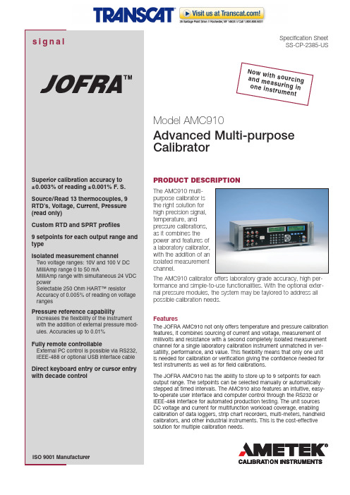
Specification Sheet SS-CP-2385-USPRODUCT DESCRIPTIONThe AMC910 multi-purpose calibrator is the right solution for high precision signal, temperature, and pressure calibrations, as it combines the power and features of a laboratory calibrator, with the addition of an isolated measurement channel.The AMC910 calibrator offers laboratory grade accuracy, high per-formance and simple-to-use functionalities. With the optional exter-nal pressure modules, the system may be taylored to address all possible calibration needs.FeaturesThe JOFRA AMC910 not only offers temperature and pressure calibration features, it combines sourcing of current and voltage, measurement of millivolts and resistance with a second completely isolated measurement channel for a single laboratory calibration instrument unmatched in ver-satility, performance, and value. This flexibility means that only one unit is needed for calibration or verification giving the confidence needed for test instruments as well as for field calibrations.The JOFRA AMC910 has the ability to store up to 9 setpoints for each output range. The setpoints can be selected manually or automatically stepped at timed intervals. The AMC910 also features an intuitive, easy-to-operate user interface and computer control through the RS232 or IEEE-488 interface for automated production testing. The unit sources DC voltage and current for multifunction workload coverage, enabling calibration of data loggers, strip chart recorders, multi-meters, handheld calibrators, and other industrial instruments. This is the cost-effective solution for multiple calibration needs.Model AMC910Advanced Multi-purpose CalibratorN ow wi t h s ou r c i n ga n d me a s u r i n g i no n e i ns t r u m e n t2Direct keyboard entry (1)The JOFRA AMC910 provides simple, front-panel entry of mode,range, and value. Using direct keyboard entry (1), the exact valuedesired is entered using the numeric keys, and the ENTER keyis pressed to set the output to that value. Whichever way youchoose, setup is simple and fast. In the voltage output mode, theJOFRA AMC910 auto-ranges on the entered value for maximumaccuracy at all times.Curser entry (2)Using cursor entry (2), the LEFT/RIGHT arrow keys are used tomove the cursor under the digit in the display to be changed. TheUP/DOWN arrow keys increment/decrement the value at the cur-sor position.Choose the mode you want (3)Voltage ModeThe JOFRA AMC910 offers four precision voltage output ranges(100mV, 1V, 10V, and 100V) all with ±0.003% of reading ±0.001%F. S. accuracy. These ranges are ideal for calibrating a broadrange of DC voltage instrumentation. Additionally all voltageoutputs settle to full specification in less than 200ms making theJOFRA AMC910 ideal for automated calibration systems.An automatic stand-by mode (3) assures that output voltagesabove 30VDC must be acknowledged by the operator before thevoltage appears at the output jacks. The stand-by mode is alsotriggered if the output current compliance is exceeded, therebyprotecting the device under calibration.Current ModeThe JOFRA AMC910 features a precision current output range(100mA) that offers 0.01% accuracy, which is ideal for calibratingprocess instrumentation especially 4 to 20mA equipment. Witha full 12 volts of compliance at 100mA virtually any precision DCcurrent measuring device can be calibrated using the JOFRAAMC910. Like the voltage ranges the current range offers quicksettling time and an operate/stand-by mode.Thermocouple ModeThe JOFRA AMC910 can read and source any of 11 typesof thermocouples. Its T/C input and output is Cold JunctionCompensated, using an ultra-stable PT-1000 sensor.RTD ModeThe JOFRA AMC910 can read and source 9 RTD types as well asYSI-400 and Ohms for non-standard curves. Probe coefficients (A,B, C, and R0) can be entered directly, with storage for up to fivecustom curves and one SPRT curve. The performance of the JOFRAAMC910 in the RTD mode compares to dedicated RTD measure-ment instruments. Unlike low-cost, less accurate RTD instruments,the display in the JOFRA AMC910 is always active, reading to threedecimal places, using polynomial averaging to extract a high accu-racy signal. The result is a very high accuracy reading.Pressure ModeSignal calibration capabilities of the JOFRA AMC910 include, cur-rent, voltage and resistance. In temperature mode, the unit can readand source any of 11 types of thermocouples and 9 RTD types aswell as YSI-400 and Ohms for non-standard curves. In pressuremode, the instrument operates with all JOFRA APM modules andcovers pressure ranges from vacuum to 700 bar / 10,000 psi, select-able through more than 60 different pressure modules, representingvacuum, absolute, gauge and compound pressure types as well asSetpoint Control (4 and SPT)A SHIFT key (4) provides easy accessto the setpoint controls of the JOFRAAMC910. Up to nine setpoints canbe defined for each output mode andeach thermocouple and RTD type.Setpoints are recalled individually atthe touch of three buttons, SHIFT (4),SETPOINT (SPT) button and then thecorresponding numeric keys 1-9. Anynumber of sequential setpoints canbe stepped through automatically,with complete control of dwell time.Either way, for rapid setup of repeat-able tests, no other instrument comesclose to the JOFRA AMC910.Remote Control (4)All of the JOFRA AMC910 operating functions can be accessedvia RS232, IEEE-488 or optional USB interface cable using astandard PC running Windows® HyperTerminal or other soft-ware using an ASCII protocol. Custom control programs maybe written using programming software such as C++. Switchingbetween LOCAL and REMOTE is as simple as touching theSHIFT (4) and LOCAL buttons.Rock-Solid StabilityThe accuracy of the JOFRA AMC910 is specified for both 90-dayand one-year intervals. Manual zero calibrations can be made onall T/C and pressure functions to eliminate offsets.Flexible Output (5, 6 and 7)Five-way copper alloy binding posts (5) provide a wide range ofconnection options. A standard pressure module connector isprovided (6), as is the CJC T/C mini-jack (7).Isolated Measurement Channel (8 and 9)The JOFRA AMC910 features a fully isolated measurement chan-nel which allows the user to calibrate process transmitters andsignal isolators. In reality it’s like having two instruments in one!This channel also incorporates a 24 volt loop power supply topower 2-wire transmitters and a HART interface resistor enablingdirect connection to HART communicators. Key features are:Two voltage ranges 10V and 100V DCMilliamp range 0 to 50mAMilliamp range with simultaneous 24 volt power (0 to 24ma)Selectable 250 ohm HART resistorAccuracy of 0.005% of reading on all ranges•••••3SPECIFICATIONS AMC910(1 year at 23°C ±5°C; % of reading, unless otherwise noted)Output VoltageRange..0 to 100.000 mV, 0 to 1.00000 V, 0 to 10.0000 V, 0 to 100.000 V Resolution0 to 100 mV Range ..................................................................1 μV 0 to 1 V Range .......................................................................10 μV 0 to 10 V Range ...................................................................100 μV 0 to 100 V Range ....................................................................1 mV Accuracy (% of reading)0 to 100 mV Range ................................±0.003% (30ppm) ± 3 μV 0 to 1 V Range .....................................±0.003% (30ppm) ± 10 μV 0 to 10 V Range .................................±0.003% (30ppm) ± 100 μV 0 to 100 V Range ..................................±0.003% (30ppm) ± 1 mV Maximum Burden (~ 1 Ohm output impedance)0 to 100 mV Range ...............................................................10 mA 0 to 1 V Range ......................................................................10 mA 0 to 10 V Range ....................................................................10 mA 0 to 100 V Range ....................................................................1 mA Output CurrentRange ...................................................................0 to 100.000 mA Resolution ................................................................................1 μA Accuracy (% of reading) .................................± 0.005% ± 1 Count Maximum Burden .....................................................................10 V ThermocouplesOutputTypes ....................................J, K, T, E, R, S, N, B, L, U, C, BP, XK Range .........................................................................................mV Resolution ........................................................................0.1 °C/°F Accuracy ....................................................0.14 °C; Type J, typical InputTypes ....................................J, K, T, E, R, S, N, B, L, U, C, BP, XK Range .........................................................................................mV Resolution ......................................................................0.01 °C/°F Accuracy ....................................................0.14 °C; Type J, typical RTDOutput Range ....................................Pt385 (100, 200, 500, 1000), Pt392, ................................................Pt3916 (JIS), Ni120, Cu 10, YS I400Resolution .......................................0.01 °C/°F; Pt385-100, typical Accuracy ..............................±0.05°C / 0.09°F; Pt385-100, typical Input (All RTD inputs are 4 wire)Range ....................................Pt385 (100, 200, 500, 1000), Pt392, ........................PT3916 (JIS), Ni120, Cu10, YSI400, 25 Ohm SPRT Resolution ......................................0.001°C/°F; Pt385-100, typical Accuracy ..............................±0.02°C / 0.04°F; Pt385-100, typical OhmsOutput Range ........................................................................5 to 4000.0 ΩResolution .....................5 to 400.00 Ω .............................0.001 Ω........................................5 to 4000.0 Ω ...............................0.01 ΩAccuracy ........................5 to 400.00 Ω .............................±0.05 Ω........................................5 to 4000.0 Ω ...............................±0.3 ΩInput (4 wire connection)Range ......................................................................0 to 4000.00 ΩResolution .....................0 to 400.00 Ω ...............................0.001 Ω ........................................0 to 4000.0 Ω ...............................0.01 ΩAccuracy ........................0 to 400.00 Ω .............40 PPM ±0.002 Ω........................................0 to 4000.00 Ω .............40 PPM ±0.02 ΩPressureRange .......................................................0 to 700 bar / 10,000 psi Compatibility ...........................All JOFRA APM pressure moduels Isolated Measurement ChannelRange ...............................................................................Accuracy 0-10.0000V .........................................................±0.005% ± 0.2mV 0-100.000V .........................................................±0.005% ± 2.0mV 0-52.0000mA ...........................................................±0.01% ± 1μA Loop power: .................................................................24 V ± 10%HART™ resistor: ...........................................................250Ω ± 3%Maximum current: .................................................................24 mA StabilityWarm-up Time .................................30 minutes to rated accuracy Temp. coefficient (t<18°C/t>28°C) ........10% of accuracy spec/°C Temp. coefficient (t<64°C/t>82°C) ..........5% of accuracy spec/°F EnvironmentalOperating Temperature ..............................0 to 50°C / 32 to 122°F Storage Temperature ...............................-20 to 70°C / -4 to 158°F Operating humidity ........................................< 80% to 30°C / 86°F ......................................................................< 70% to 40°C / 104°F ......................................................................< 40% to 50°C / 122°F Storage humidity ........................................<95%, non-condensing Power RequirementsVoltage Range .........................................................90 to 240 VAC ....................................................................................... Max. 15 VA MechanicalDimensions (h x w x d): ..............17.7 cm x 48.26 cm x 27.96 cm / .............................................................................5 in x 19 in x 11 in Weight ...................................................................4.8 kg / 10.5 lbs Display 2 Large character 16 by 2 line alphanumeric backlit LCDsOrder No.Description Base model numberAMC910AMC910 Advanced Multi-purpose Calibrator Power supply115 115 VAC, 50/60 Hz 220 230 VAC, 50/60 Hz Mains power cable type A EUROPEAN, 230 V B USA/CANADA, 115 V C UK, 240 VD SOUTH AFRICA, 220 VE ITALY, 220F AUSTRALIA, 240 VG DENMARK, 230 VH SWITZERLAND, 220 VI ISRAEL, 230 VCertificateG NIST traceable certificate (standard)HAccredited certificateAMC910115BG Sample order numberJOFRA AMC910 for 115 VAC with NIST traceablecertificate.ORDERING INFORMATIONAMETEK Calibration Instrumentsis one of the world’s leading manufacturers anddevelopers of calibration instruments fortemperature, pressure and process signalsas well as for temperature sensors both froma commercial and a technological point of view.JOFRA Temperature InstrumentsPortable precision thermometers. Dry-block andliquid bath calibrators: 4 series, with more than25 models and temperature ranges from-90° to 1205°C / -130° to 2200°F. All featuring speed,portability, accuracy and advanced documentingfunctions with JOFRACAL calibration software.JOFRA Pressure InstrumentsConvenient electronic systems ranging from-1 to 1000 bar (25 inHg to 14,500 psi) -multiple choices of pressure ranges, pumps andaccuracies, fully temperature-compensatedfor problem-free and accurate field use.JOFRA Signal InstrumentsProcess signal measurement and simulation foreasy control loop calibration and measurementtasks - from handheld field instruments tolaboratory reference level bench top instruments.JOFRA / JF Marine InstrumentsA complete range of calibration equipmentfor temperature, pressure and signal,approved for marine use.FP Temperature SensorsA complete range of temperature sensorsfor industrial and marine use.M&G Pressure TestersPneumatic floating-ball or hydraulic piston deadweight testers with accuracies to 0.015% of reading.M&G PumpsPressure generators from small pneumatic“bicycle” style pumps to hydraulic pumpsgenerating up to 1,000 bar (15,000 psi)....because calibration isa matter of confidenceJOFRA AMC910 calibratorInstruction manualAC line cordThermocouple shorting jumperNIST traceable certificate•••••Information in this document is subject to change without notice.©2007, by AMETEK, Inc. All rights reserved.Pub code SS-CP-2385-US Issue 0901JOFRA APM PRESSURE MODULESTo get an ideal reference system, JOFRAoffers a range of reference sensors. All JOFRASuperior Temperature Standard sensors areeconomical and offer fast response times, lowimmersion depths, compact physical sizes, andspecified low drift rates: even at high tempera-tures. These are all important considerationswhen selecting a reference sensor.Please find more information in accessory sheet AS-CP-2210, which maybe found at JOFRA STS REFERENCE SENSORSThe APM series of pressure modules by JOFRA arecompatible with the AMC900, AMC910, ASC300or APC calibrators. The JOFRA APM external pres-sure modules includes more than 60 models avail-able with gauge, absolute, differential, and vacuumpressure references and in metric and imperialengineering units. The modules are engineered forin-plant, field, or laboratory use. They are ready-to-use with the JOFRA AMC910 and the protocolallows for immediate recognition and use of themodule once plugged into the calibrator.Please find more information in specification sheet SS-CP-2190, whichmay be found at STANDARD DELIVERYACCESSORIESPart No. Description121985 Extension cable for Pt100 sensor, length 5.0 m121983 Extension cable for Type K - 5 m122523 Extension cable for Type N - 5 m120519 Thermocouple Male Plug - Type Cu-Cu - White120518 Thermocouple Male Plug - Type R / S - Green120517 Thermocouple Male Plug - Type K - Yellow120516 Thermocouple Male Plug - Type J - Black120515 Thermocouple Male Plug - Type T - Blue120514 Thermocouple Male Plug - Type N - Orange2206011 Thermocouple plug + K wire + alligator2206012 Thermocouple plug + T wire + alligator126812 Cable for USB to serial105366 Cable for RS232104203 Test lead set。
ScoutUSBL

Analyze the impact of sound speed variations, multipath
propagation, and other factors on positioning accuracy
02
Equipment error
Evaluate the performance of transmitters, receivers, and other
accuracy
Optimization strategy and improvement direction
Multi sensor fusion
Develop algorithms to fuse measures from multiple sensors, including acoustic, inertial, and optical sensors, to improve positioning accuracy and robustness
Error Detection and Correction
Detects and corrections errors in received data, improving the overall reliability of the system
ScoutUSBL
03 positioning technology
ScoutUSBL
contents
目录
• ScoutUSBL Overview • ScoutUSBL system composition • ScoutUSBL positioning technology • ScoutUSBL data transmission and
glossaryofterms

Administrative Services Planning Council (ASPC): The shared governance council for the Finance and Administrative Services Division.Americans with Disabilities Act (ADA): Federal regulation that insures that all facilities are constructed with equal access for persons with disabilities.Annual Implementation Plan (AIP): Annual review process for the goals and objectives as defined within a Strategic Plan time period.Apportionment: Federal, state or local monies distributed to college districts or other governmental units according to certain formulas.Assigned Square Feet (ASP): A term used to identify facility footage assigned to classrooms, labs, and non-instructional spaces.Association of Physical Plant Administrators (APPA): This is an international group that deals with the maintenance and operational standards for all levels of colleges and universities. Budgeting and Accounting Manual (BAM): The BAM has the authority of regulation in accordance with Title 5 Section 59011 of the California Code of Regulations (CCR), is distributed as part of the Board of Governors' responsibility to define, establish, and maintain the budgeting and accounting structure and procedures for the California Community Colleges as defined in California Education Code (EC) Section 70901.California Community College Chancellor's Office (CCCCO): The CCCCO is currently comprised of 72 districts, 109 campuses, 64 approved educational centers, and 20 separately reported district offices. These assets include 58.4 million gross square feet of space housed in 4,629 buildings atop more than 20,489 acres of land. Website: California Environmental Quality Act (CEQA): This is a document that provides statutes and guidelines for construction projects in the State of California.California Field Act (Field Act): A set of construction standards for school buildings to be earthquake resistive.Capacity Load Ratio (CAP Load Ratio): The ratio is a calculation based upon the number of Weekly Student Contact hours and the amount of instructional space based upon ASF. The ratio indicates how well the district utilizes its space and is used to determine eligibility for new space. Capital Outlay Budget Change Proposal (COBCP): This document is prepared by the Chancellor's Office staff for submittal to the Department of Finance (DOF) for inclusion in the Governor's spending plan that funds State construction projects.Capital Outlay: The acquisition of or additions to fixed assets, including land or existing buildings, improvements of grounds, construction of buildings, additions to buildings, remodeling of buildings, or equipment.Capital Projects: Funds that are used for the acquisition or construction of capital outlay items, e.g. buildings, major equipment.Certificates of Participation (COPs): Are used to finance the lease/purchase of capital projects. Essentially, they are the issuance of shares in the lease for a specified term.Change Order (CO): A term used to describe additional work or duties required during a construction project.Change Order Request (COR): A term used to describe a request by the contractor for a change order.Community College Facilities Coalition (CCFC): Was formed to provide advocacy for facilities’ issues and critical information and services to California's community college districts and their business partners on facility matters. Website: Community College League of California (CCLC): Is a nonprofit public benefit corporation whose voluntary membership consists of the 72 local community college districts in California. Website: Design Development Package (DD Package): This is a term used to identity the first phase in the development of construction plans and specifications.Division of the State Architect (DSA): This is the state organization that approves the plans and specifications for community college construction projects.Education Code: The body of law that regulates education in California. Other laws that affect colleges are found in the Government Code, Public Contracts Code, Penal Code and others.Encumbered Funds: Obligations in the form of purchase orders, contracts, salaries, and other commitments for which part of an appropriation is reserved.Environmental Impact Report (EIR): A document that is prepared to address any environmental impacts associated with construction project(s).Escondido Center (EC or EC CNTR): Palomar College's Education Center. (Note: The District has outreach sites in addition to this center.)Expenditures: Amounts actually dispersed for the expenses associated with operations of a fund. (Note: Accounts kept on an accrual basis include all charges whether paid or not. Accounts kept on a cash basis include only actual cash disbursements.)Facilities Condition Index (FCI): A rating used to determine the condition of a building or area. This standard has been adopted by the Building Owners & Managers Association (BOMA), the Council on Educational Facilities, and the American University Planners Association.Facilities Review Committee (FRC): A district shared governance committee that reviews and comments on requests for changes in the District's buildings and grounds which reports to ASPC. Final Project Proposal (FPP): Term used to describe the final proposal that is sent to the State for approval and funding for state capital outlay projects. (Note: The State must approve the IPP before an FPP can be submitted.)Financial and Compliance Audit: An examination leading to the expression of an opinion on (1) the fairness of presentation of the audited entity's basic financial statements in conformity with GAAP, and (2) the audited entity's compliance with the various finance-related legal and contractual provisions used to assure acceptable governmental organizational performance and effective management stewardship. Public sector oversight bodies typically require independent auditors to include responses to standardized legal compliance audit questionnaires in financial and compliance audit reports.Fiscal Year: Twelve calendar months; for governmental agencies in California, it is the period beginning July 1 and ending June 30. Some special projects use a fiscal year beginning in October 1 and ending September 30, which is consistent with the federal government's fiscal year.Foundation for California Community Colleges (FCCC): Assists community colleges and other partner schools to operate more effectively and efficiently through donations, grants, programs and services. FCCC is the sole auxiliary for the CCC Board of Governors, Chancellor and Systems Office. Website: Full-Time Equivalent Students (FTES): A measurement used to convert part-time and full-time student headcount into a full-time load equivalent. An FTES represents 525 class (contact) hours of student instruction/activity in credit and noncredit courses. FTES is one of the workload measures used in the computation of state aid for California Community Colleges.Fusion: The integrated web-based software system that all community colleges use to manage space, capital construction plans, facilities condition assessments. All project proposals for State funded projects are submitted through FUSION.General Fund: The fund used to account for the ordinary operations of the district. It is available for any legally authorized purpose not specified for payment by other funds.General Obligation Bond, Proposition 39 (GO39): An initiative that reduced the percent of voters required for passage of local bonds for K-12 and community colleges to 55% of electorate. (Note: GO39 bond propositions may only be presented to electorate in even year elections.)Generally Accepted Accounting Principles (GAAP) & Generally Accepted Accounting Standards (GAAS): Uniform minimum standards and guidelines for financial accounting and reporting.Governing Board Resolution (GBR): Resolution passed by Palomar College's Governing Board.Governmental Accounting Standards Board (GASB): The authoritative accounting and financial reporting standard-setting body for governmental entities.Gross Square Feet (GSF): A term used to identify the total facility space in a building. Heating, Ventilation and Air Conditioning (HVAC)Human Resources Planning Council (HRPC): The shared governance council for Human Resources.Independent Citizens Oversight Committee (ICOC)Indoor Air Quality (IAQ)Initial Project Proposal (IPP): Term used to describe the initial proposal sent to the State for approval and funding for state capital outlay projects.Instructional Services Planning Council (IPC): The shared governance council for the Instruction Division.Intermediate Distribution Frame (IDF): This identifies a cable rack in a room that interconnects and manages the telecommunications wiring between itself and any number of IDFs and manages the telecommunications wiring between a MDF and the workstations.JCAF 31 Analysis of Building Space Use & WSCH: Required form for State funded projects. JCAF 32 Cost Estimate Summary and Project Time Schedule: Required form for State funded projects.JCAF 33 Guideline based Group 2 Equipment Cost Estimate: Required form for State Funded projects.Leadership in Energy and Environmental Design (LEED): A "green building" rating system developed and administered by the US Green Building Council, Washington D.C.Lease Revenue Bonds: Bonds secured by a lease agreement and rental payments. Community colleges use lease revenue bonds to finance construction or purchase of facilities.Main Distribution Frame (MDF): This identifies a cable rack in a room that interconnects and manages the telecommunications wiring between itself and any number of IDFs.Palomar Community College District (PCCD)Palomar Community College District Master Plan 2022 (MP2022)PeopleSoft: The integrated database system used by Palomar College.Preliminary Plans Package (PP Package): A term used to identify the early phase in the development of construction plans and specifications.Preventive Maintenance (PM): Program that provides preventive maintenance services to every building and grounds area owned by the District.Resource Allocation Committee (RAC): Palomar College's budget committee which reports to SPC. (Note: The name has been changed effective December 2007 to Budget Committee.)San Diego Association of Governments (SANDAG): The eighteen cities and San Diego county government serve as a forum for regional decision-making. SANDAG builds consensus, makes strategic plans, obtains and allocates resources, plans, engineers, and builds public transportation, and provides information on a broad range of topics pertinent to the region's quality of life.Scheduled Maintenance: Major repairs of buildings and equipment. Matching state funds are available to districts to establish a scheduled maintenance program as approved in the State's Annual Budget Act.Solar Panels (SOLAR): A term is used to describe solar panels that are used in the heating of hot water systems.Solar Photo Voltaic (SOLAR PV): A type of solar system that converts the sun's energy into electrical energy.State Administrative Manual (SAM)State Apportionment: An allocation of state money to a district, determined by multiplying the district's total FTES times its base revenue per FTES.State Scheduled Maintenance (SSM): Program that provides a 50-50 match for specific scheduled maintenance projects. The District is required to submit a 5-year Scheduled Maintenance Plan to the State annually.Strategic Planning Council (SPC): Palomar College's primary shared governance council. Reporting to SPC are IPC, SSPC, ASPC and HRPC, which represent the four primary divisions of the college.Student Services Planning Council (SSPC); The shared governance council for the Student Services Division.Title 5 California Code of Regulations: The section of the California Administrative Code that regulates community colleges. The Board of Governors adopts Title 5 regulations.Total Quality Management (TQM)Value Engineering (VE)Voice Over Internet Protocol (VOiP): Telephone system that uses the internet and computer for communications.Weekly Student Contact Hours (WSCH): The number of hours a student has face-to-face contact with an instructor.Working Drawing Package (WD Package): A term used to identify the later phase in the development of construction plans and specifications.。
acoustics翻译
acoustics翻译acoustics(音响学)是研究声音传播、声音产生和声音的物理特性的学科。
它涉及到声波在各种媒介中的传播、反射、折射、衍射和吸收等现象。
以下是一些关于acoustics的用法和中英文对照例句:1. The study of acoustics helps us understand how sound travels through different mediums. (音响学的研究帮助我们了解声音如何在不同的介质中传播。
)2. The acoustics of the concert hall were carefully designed to ensure optimal sound quality. (音乐厅的音响效果经过精心设计,以确保最佳的音质。
)3. The acoustics in this room are terrible. We need to add some sound-absorbing panels. (这个房间的音响效果很糟糕。
我们需要添加一些吸音板。
)4. Architectural acoustics focuses on designing spaces to enhance sound quality and reduce unwanted noise. (建筑音响学专注于设计空间,以提高声音质量并降低不必要的噪音。
)5. The acoustics of the cathedral are breathtaking. The sound echoes beautifully throughout the space. (大教堂的音响效果令人惊叹。
声音在整个空间中回荡得很美。
)6. The study of underwater acoustics is important for understanding marine life and monitoring oceanenvironments. (水下声学的研究对于了解海洋生物和监测海洋环境非常重要。
FLIR B250无人机温度相机用户手册说明书

FLIR's newB250infrared camera delivers a high resolution detector,along with text and voice features to help building professionals accurately diagnose and document building conditions.High quality 200x 150IR resolution Thermal sensitivity of 70mK (NETD)Integral 1280x 1024visible light camera Video lamp for quality visible images>>>>>>>>FLIR B250INFRARED CAMERAInterchangeable lens for greater versatility Picture in Picture to show fusion images Touch screen text,image marker,sketch,voice Humidity/Dew Point and Insulation AlarmsThe Global Leader in Infrared CamerasEasy and Versatile SolutionFLIR's B250infrared camera weighs less than two pounds,making it a versatile camera for finding energy waste,water intrusion,and other conditions in buildings and facilities.Thecamera's light weight and comfortable form is attributed to a small advanced IR detector and innovative battery design.Investment ProtectionThe B250is a mid-level camera in the B-Series lineup and is upgradeable so your investment in technology,software,and training is protected.Simply add higher-model B-Series features as your needs change and grow.Entry-level and experienced thermographers will benefit from the ease of use and productivity features of the B250camera.Touch Screen TechnologyThe B250camera includes higher resolution and touch screen features,which let you save text,sketches,and markers to your thermal images,directly on your camera at your work site.The on-screen sketch,marker,and text touch features help you increase productivity and enhance your reports.Voice and HeadsetSimply connect a headset to your B250and record voice information along with the images you take.Inspect with ConfidenceThe B250model includes FLIR’s exclusivehumidity/dew point and insulation alarms.The alarms make it easy to scan buildings and homes to find conditions that cause damage and energy waste.Find Trouble FastThe B250camera's 70mK thermal sensitivity helps you pinpoint trouble fast.The camera includes 200x 150IR resolutionwhich translates to 30,000pixels.That's one-third more detail than competing brands with 160x 120resolution.Advanced OpticsThe B250comes with a 25°lens for normal views.An optional 45°lens is available for wide-angle images.And a 15°telephoto lens is available for long-range work.The T-series lenses areinterchangeable and easily attach to the camera body.Tilting only the optic,allows intuitive and productive use of the camera for extendedperiods of time.This is a benefit to organizations that regularly conduct detailed building surveys.Produce Sharp ImagesAuto and manual focus features of the B250allow a wide range of users to take advantage of the camera.This ensures everyone can take sharpthermal images and produce accurate temperature analysis and results.The camera's 2x digital zoom capability helps you zoom in to get close detail in a range of applications.1.3Mega Pixel Visible Light CameraThe B250includes an integral visible light camera to add visual information to reports.On-camera Picture in Picture (PIP)image fusion capability is provided as well so users can see a scalable infrared image super-imposed in a visible light image.A standard video-out port enables users to display images on a virtual reality Heads Up Device (HUD).This extends the use of the camera in tight spots and special applications.T-Series cameras also connect to a standard off-the-shelf video display device for viewing of IR images by a large audience.Information-Packed Radiometric ImagesUSB port connection enables convenient image downloading from the B250to your PC.All the valuable information you collect in the field,such as temperature data,object parameters,and text/image information is saved with the IR image files you download to your PC.This simplifies data collection and allows for quick and efficient processing of information after your field work is done.The B250includes QuickReport analysis andreporting software.Optional Reporter software,a Microsoft®Word-based program -is available from FLIR for advanced analyses and report generation.ThermaCAM is a registered trademark and FLIR Systems is trademark of FLIR Systems.This product is protected by patents,design patents,patents pending,or design patents pending.FLIR B250Technical SpecificationsFrom Left to right:USB mini for PC image download,4pole audio for voice annotation,NTSC video,USB-A for memory stick image transfer。
- 1、下载文档前请自行甄别文档内容的完整性,平台不提供额外的编辑、内容补充、找答案等附加服务。
- 2、"仅部分预览"的文档,不可在线预览部分如存在完整性等问题,可反馈申请退款(可完整预览的文档不适用该条件!)。
- 3、如文档侵犯您的权益,请联系客服反馈,我们会尽快为您处理(人工客服工作时间:9:00-18:30)。
Measurement of Workload for Voice User Interface SystemsTakuya NISHIMOTO *, Motoki TAKAYAMA **, Haruaki SAKURAI **,and Masahiro ARAKI *** Graduate School of Information Science and Technology, The University of Tokyo, Hongo 7–3–1, Bunkyo-ku, Tokyo, 113–8656 Japan** Faculty of Engineering and Design, Kyoto Institute of Technology,Matsugasaki, Sakyo-ku, Kyoto, 606–8585 Japan1. IntroductionRecently, with the maturation of speech synthesis and speech recognition technology, voice interface enabling interactions between machine and human has become possible through the use of several spoken dialog systems. Two advantages of voice operations for information acquisition and machine operations are: (1) Hands-free: Keyboard operations or pointing gestures are no longer necessary, making the system suitable for the non-desktop environment, (2) Eyes-free: Visual attention to the display is no longer necessary.When a voice-alone human-machine interface system is used, however, the user may feel fatigue from speaking for many hours. Moreover, the difficulties of understanding voice commands and the problem of assessing whether the user's utterances are accepted correctly may also exhaust the user. These kind of problems partly result from the quality of the synthesized voice (poor understandability, etc.), or the performance of speech recognition (low recognition rate, long response time, etc.). They may also result from the failure of the interaction design, which depends on the dialog patterns, vocabulary of speech input, and the choice of words in response sentences.In this paper, various workloads using spoken dialog systems are grouped together as the dialog workload. Dialog workload includes both the physical process of speaking and so on, and the cognitive process of mental activities such as remembering, searching, reasoning, paying attentions, etc. Measuring the dialog workload involves not only comparing the physical processes such as the number of the utterances required to finish a task, but also involves the cognitive processes, such as the level of attention that the user must pay to the system. The measurement of dialog workload isexpected to show the ease of use, or the mental margins for using modalities other than the voice (visual, etc.). It can be used to know whether or not a voice interface system is appropriate for situations such as walking or driving a car.To make the spoken dialog system easy to use, it is important that the interaction design is planned in the early stages of development. Evaluations by users and improvements by the developer are on-going tasks that must be repeated [1, 2]. This can be performed efficiently without using the subjective opinions of users if the dialog workload is analyzed section by section to evaluate which parts need improvement. We propose a method of measurement for assessing the dialog workload in voice interface systems, followed by basic evaluations.Dual-task methods are commonly used for the measurement of the level of attention to an object [3, 4, 5]. While performing a task, humans may have to divide their attention when other tasks are added. The Law of Fixed Capacity states that the human mental focus is limited, although to a certain degree it is possible to divide mental attention among different tasks. When the amount of the workload exceeds the upper limit of mental resources, a longer response time and/or an increase in errors may occur while doing the tasks.The organization of this paper is as follows: The second section contains related works and unsolved problems in evaluating voice user interface systems using dual-task methods. The third section explains our method. The forth section describes the preliminary experiments for testing the effectiveness of the proposed method. The fifth section discusses the experiments applying our method on a spoken dialog system. The sixth section states the summary and shows the problems that need to be solved.2. Related WorksWe propose a method for measuring the dialog workload of voice interface systems using the dual-task method (Figure 1).(Figure 1: Measurement of workload for voice interface systems.)The use of the voice interface system is regarded as the primary task, and a video game task or a driving simulator task in which the workload can be measured objectively is regarded as the secondary task. Subjects are asked to perform those tasks simultaneously. In situations where the performance of the secondary task is poor, the workload of the voice interface system is judged to be relatively high. Thus in Figure 1, the smaller black performance bar shown in dialog system B indicates that the task workload is heavier than that of the dialog system A.To perform such experiments, the following conditions must be met: (1) The Law of Fixed Capacity applies, (2) The subjects can intentionally give priority to the primary task, and (3) The differences of performance in the secondary task are easily compared and reliable.There are several related works which use multiple and simultaneous tasks that are specifically planned for the evaluation of voice user interface systems in the car driving environment.Kojima et. al. [6, 7] performed subjective experiments with three tasks including car-driving, reactions to stimuli of LED displays, and shadowing of words.Their results showed that the shadowing task affects the performance of the stimuli-reaction task (no significant difference in average reaction time was observed, but the ratio of trials in which reaction times were relatively long increased.) Their experiments have shown the weak points of using spoken dialog, but comparisons of the strength of influence among the dialog patterns have not been made.Shimizu et. al [8] evaluated spoken dialog systems for car drivers from the viewpoint of safety. In their experiments, subjects were asked to perform three tasks including car-driving, reaction to the stimuli of LED displays, and spoken dialog task; however, the differences in influence among the dialog patterns were not shown. In their experiment, subjects drove a car on a circuit while performing other tasks including the stimuli reaction task and the spoken dialog task (traffic information retrieval). Their secondary task corresponds to both the driving task and the reaction task. It is difficult, however, to manage the priorities of each task, so the performance of the reaction task does not directly reflect the dialog system workload. Another difficulty is that unlike the reaction task, driving performance can not be objectively assessed.Strayer et. al [9] investigated using the dual task method how conversation with mobile phone affects driving task. In their experiment, subjects perform a simulated driving task (steering on a course generated by adding three sinusoidal waves), a reaction task (when the red signal turns on, the subjects depress the brake pedal as soon as possible), and a spoken dialog task. Their results showed that conversation on a mobile phone had negative effects on both the simulated driving task and the reaction task. It was also shown that the difference in mobile phone shape (e.g. hands-free type, handheld type, etc.) does not have an effect on the task performances. They also reported that the word shadowing (repeating) task does not have affect on the driving task, but the word generation task (associating new words with given words) may affect driving.Their study proved that the dual task method is useful between the primary task involving both visual attention and hand operation and the secondary task involving voice conversation. Their experiments, however, involve a triple task condition including steering and reaction to signals, not a dual task situation. Their method of workload measurement may not be appropriate for the evaluation of the word shadowing task because it can only measure a relatively large workload.In a related experiment, Uchiyama et. al. [10] made an attempt to quantify the driver’s capacity using a dual task method. They developed a voice interface system which adapts to driver’s situation, estimating the driver’s workload capacity using driving conditions. It displays information using spoken dialog when the driver isexpected to have adequate capacity.3. Proposed MethodFrom the viewpoint of comparing dialog workloads, priority is given to the following points in choosing the secondary task;(1) The results of the performance can be obtained periodically under the same conditions. In this situation, the similarity between the real task such as driving and the experimental task is not regarded as important.(2) The task has a certain level of difficulty so that practice will have little effect on the results.(3) The subjects can intentionally give priority to the primary task, i.e. the use of the spoken dialog system.Using our experimental method, it is expected that we can specify the positions where the dialog workloads are relatively high in a dialog system. Even if the dialog system is designed for drivers and the secondary task in the real environment is car-driving, the magnitude relationship of the dialog workloads among the positions in the dialog may be the same as that under the conditions of our proposed method.From such a viewpoint, we chose a PC game called ‘the Left or Right’ as the secondary task in our experiment [11, 12]. The screen image of our game is shown in Figure 2. The software is developed with Microsoft Visual Basic 6.0 and the target operating system is Microsoft Windows 2000.(Figure 2: Screen image of the game used for workload measurement.)There are two blank boxes with arrows beneath them on the left of the window. When a left pointing arrow appears in the left box, or a right pointing arrow appears in the right box, the player indicates “correct” by pressing the upper key. When the upper and lower arrows point in different directions, the player presses the lower key to indicate “incorrect.” A random arrow then appears one second after pressing the upper or lower arrow key, irrespective of success or failure. During the play, all events such as displayed arrows and pressed keys are recorded with the player’s response time measured in milliseconds.The experimental procedure is as follows; at first, the subjects practice the game until they are fully accustomed to it. After this, the subjects perform the spoken dialog task as the primary task and the game as the secondary task. In advance of the experiment, the subjects are instructed to give priority to the spoken dialog task during the dual task condition, and respond as quickly and correctly as possible.After the experiment, response times of each trial are statistically processed factoring in the level of difficulty of the spoken dialog task that was performed simultaneously. We judge the dialog workload during a period of time as significantly high, if the game response time during the period is significantly longer than those of the others.4. Preliminary ExperimentTo validate the proposed method, we performed a preliminary experiment to affirm that the workloads of the two spoken dialog tasks are different. The workload of the spoken dialog is determined taking into account both the cognitive and the physical workloads. Factors such as listening to system messages, remembering messages, judging the time to allot for response, and activation of speech organs to make utterances, etc. affect the difficulty of task and the response time.As a simulated dialog task which produces such a workload, we use the listening and repeating of words task (word shadowing task). The number of words which a subject remembers simultaneously determines whether the workload difference is significant. This experiment was designed along the lines of the research of Uchiyama et. al. [10], although where Uchiyama's group used the word shadowing task as the secondary task, we used it for the primary task.4.1 Procedure of ExperimentThe examples of the word shadowing task are shown in Table 1 and 2. Two or four Japanese words are spoken to prompt the subject’s answers. Followed by a beep sound, the subject answers remembered words one by one. The order of answered words is not restricted. The procedure mentioned above is counted as one trial of the word shadowing task. Approximate time required for one trial is 20 seconds. The trials are repeated followed by a time interval which is selected randomly between 10-20 seconds. The scheduled intervals between prompts and answers are selected so that the total duration of the different tasks (Table 1 and Table 2) is approximately same, although the timing of the individual steps within the tasks is not.Table 1: Words shadowing task - 2 words.Prompts (in Japanese) User's responses"Robotto" (robot) (followed by 3.5sec silence)"Taremaku" (banner) (followed by 3.5 sec silence)(beep sound)(6 sec silence) "Taremaku"(beep sound)(2 sec silence) "Robotto"Table 2: Word shadowing task - 4 words.Prompts (in Japanese) User's responses"Robotto" (robot) (followed by 1 sec silence)"Taremaku" (banner) (followed by 1 sec silence)"Keshigomu" (eraser) (followed by 1 sec silence)"Sukiyaki" (sukiyaki) (followed by 1 sec silence)(beep sound)(2 sec silence) "Taremaku"(beep sound)(2 sec silence) "Sukiyaki"(beep sound)(2 sec silence) "Robotto"(beep sound)(2 sec silence) "Keshigomu"The vocabulary of the word shadowing task consists of 166 words. Japanese common noun words whose length is from two-moras to four-moras are randomly selected so that the frequency of appearances of the prefix syllabary characters is balanced. Both words start with dull sounds, and words which are difficult to hear clearly are removed from the vocabulary. They are randomly ordered and spoken using a commercial Text-to-Speech synthesis system (Toshiba LaLaVoice 2001).The subjects include nine men and a woman between 20-25 years old. They are divided into two groups which are named Group-A and Group-B. The subjects of Group-A perform the 4-word tasks first, followed by the 2-word tasks. Those of Group-B perform the 2-word tasks first, followed by the 4-word tasks. The experimental procedure of Group-A is as follows (in Group-B, steps 3-4 and steps 6-7 are replaced);1. The subjects listen to an explanation of the game, and practice the game.2. They perform the game task with no other tasks (for eight minutes).3. They practice the 4-word shadowing task until they are fully accustomed to it.4. They perform the 4-word shadowing task and the game task simultaneously (for eight minutes).5. They take a rest.6. They practice the 2-word shadowing task until they are fully accustomed to it.7. They perform the 2-word shadowing task and the game task simultaneously (for eight minutes).4.2 Results and DiscussionIn preparation, five male subjects, 20-25 years old, performed the first half of the procedure previously described (i.e. from step 1 to step 4). The response time of the game task increased significantly (with a risk rate of 1% for all subjects) during the performance of the 4-word shadowing task. In other words, the dual task condition required more time than the single task. Thus, we confirmed that the Law of Fixed Capacity can be applied to the proposed method. As the performance of the voice-related task during the performance of the game task may frequently exceed the capacity of human resources, the workload of the secondary task was considered appropriate.Table 3 compares the 2-word and 4-word tasks. The ** mark indicates a significant difference with a risk rate of 1%. A significant difference was observed in nine out of ten subjects.These results show that the proposed method can compare the dialog workloads of two different tasks.Table 3 : Average response time (msec) in preliminary experiments.Subject 2-word task 4-word task SignificanceA1 542 1191 **A2458 589 **486 675 ** A3496 683 ** A4A5426 562 ** B1 695 1000 **401 418 - B2B3523 868 **712 941 ** B4B5478 519 ** 5. Evaluation of the Spoken Dialog SystemIn the preliminary experiment, the subjects were asked to listen to the system prompts and to repeat the prompts. In this chapter, we evaluate the dialog workload of a spoken dialog system using our method.5.1 Outline of the Dialog SystemWe created a restaurant database-search application to be used while driving. The Japanese version of the Nuance Voice Web Server (VWS) released by OMRON Corp. was used as the platform for operating the spoken dialog system. The subject uses a headset-microphone connected with the notebook-type personal computer. The VWS requires a client software that can input or output speech. We choose Pingtel Instant Xpressa as the client for our experiment.The dialog application is written using VoiceXML 1.0 (/Voice/). The dialog is controlled with static documents which use the standard functions in VoiceXML specifications such as state-transitions and variables. The application uses a Japanese text-to-speech synthesizer to generate the responses from the system. We employed the VWS speech recognition and speech synthesis."Barge-in," or the user's interruption during the system utterances, is always enabled. Input is limited to voice responses. Other methods such as keyboards or pointing devices are not used. The speech recognition vocabulary consists mostly of isolated words. The recognition grammars are selected depending on the dialog states from 24 grammars, which contain an average of 8.3 words and a maximum of 30 words.5.2 Dialog StatesThe subjects are asked to perform the following task: "Search for restaurants within 10 minutes of their current position, find the lowest budget Chinese restaurant and reserve seats." The expected dialog states to perform the task can be divided into six states S1-S6.S1: [Main menu] The system shows various choices, and the user selects "Neighborhood Town Guide."S2: [Neighborhood town guide] The system requests search conditions such as the category or approximate arrive time. In this task, the user selects "restaurant" for the category and "within 10 minutes" for the arrival time. The user is allowed to input both items in any order. At this dialog state, the user is also allowed to input two items in one utterance, such as "restaurants within 10 minutes."S3: [Detailed category] The system shows the number of candidate restaurants. The user then adds a search condition to select only Chinese restaurants.S4: [Price choice] The system shows a price choice: "higher or lower than 1500 yen a person." The user selects the latter option.S5: [Candidates and details] The system shows the total number of restaurants which meet the conditions and lists their names. The user selects a restaurant by speaking its name. The system then shows detailed information about the restaurant, such as recommended menus and the average price level. The final choice is whether the user wants to reserve seats at the restaurant or not. If the user answers "No", the system repeats from the beginning of S5. If the user answers "Yes", the system moves to S6.S6: [Reservation and exit] The system reserves the seats and exits.5.3 Experimental MethodThe subjects include four men and a woman between 20-25 years old. All the subjects have experience with other spoken dialog systems, although they have never used this one. The subjects first practice the game until they are fully accustomed to it.Then they perform the restaurant database-search task only once. They are instructed to give priority to the spoken dialog task.After the experiments, we analyzed the recorded response times and conversations. All states from S1 to S6 correspond to the dialog patterns written in VoiceXML. We analyzed average response times of the secondary task for each state.5.4 ResultsAll subjects finished the given task. Average time to finish task was 343 seconds. The number of users' utterances ranged between 16 and 22. The average number of rejected users' utterances was 1.2 and the maximum was 5.All game response times were used for analysis regardless of the correctness of the answers. Response times (R) showed deviations; R' represents the moving averages of 5 sequential samples from R. Figure 3 shows the R and R' from the beginning to the end of a dialog session. The peaks of the moving averages (R') are more significant than the original values (R).Figure 3: Example of response time while the subject is performing spoken dialog (thinline: observed value R, bold line: moving average R')Figure 4 shows the distributions of R' of all subjects with respect to each dialog state. The box shows the median value and the range between 25-75%. The whisker plots show 10% and 90%, and the outskirt samples are plotted at both ends. Significant response delays were observed in states S2 and S5, as judged from the outskirt samples.Figure 4: Distribution of response time (msec) in each dialog state.The effect of interaction was significant (F = 2.42) according to the analysis of variance of R' with the subjects and the dialog states (S1-S6) as factors. This indicates the effects of the difference of subjects and dialog states on the response times are not independent [13]. Figure 5 shows the averages of R' with respect to each subject and dialog state. Table 4 shows the significance of the simple main effect of the different dialog states.F ratio indicates the ratio to the chance fluctuation. These results indicate that significant long average response times are observed in the following conditions: state S2 for subjects C1 and C2, and state S5 for subjects C4 and C5.Table 4: Simple main effect of difference of dialog state.ratio p Significance Subject FC1 F(5, 177) = 3.380 p = .0061 **C2 F(5, 244) = 7.222 p < .0001 **C3 F(5, 151) = 1.591 p = .0658C4 F(5, 157) = 3.010 p = .0127 *C5 F(5, 222) = 4.977 p = .0002 **5.5 DiscussionKojima et. al. [6, 7] compared the delays of response times showing a difference in the single task and the dual task conditions. The results shown in Figure 4 indicate that the response times tend to increase at the dialog states S2 and S5, indicating that our method can be used to go one step further to compare dialog states or dialog patterns under the dual task conditions.Figure 5 and Table 4 show the subject-ability effect. Our focus on the average response times was regarded as appropriate due to the significant differences observed among the different states, which are not obvious in the works of Kojima et. al.Figure 5: Average response time (msec) for each subjects C and dialog state S.The difference between the main experiments and the preliminary experiments is that the performance of the main experiments depends on subject ability, but the tasks of the preliminary experiments were too simple to reflect subject ability. Preliminary experiments in Chapter 4 thus showed that there are no significant differences between the subjects' ability using our experimental model. Therefore, the experiments in Chapter 5 show that the dialog workloads of the real spoken dialog systems may change depending on subject ability such as the knowledge and the experience of individuals.The appropriateness of our experiments can be proved if the dialogs in states S2 and S5 have adequate reasons of the delay of response time that was significant in the cases of two subjects respectively. The appropriateness of our experiments can be proved if the delays of response times seen in dialog states S2 and S5 are related to the difficulties of the tasks, as observed in the comparisons of two subjects.In the dialog S2, the users fill two slots; the category and the arrival time. Figure 6 shows the prompt in dialog state S2. The system accepts the users' utterances such as “10 minutes,” “Restaurant,” or “Restaurant within 10 minutes.” After the users’utterances if they only specify one condition such as the time only or the category only, the system asks for the other condition. This increases the dialog workload because the users may have trouble finding the appropriate words to say, while in the other situation the users merely select a voice command from the list of the candidate words spoken as a prompt.In dialog S5, the users listen to the names of restaurants, select a restaurant from the candidates, and say its name as a voice command. Figure 7 shows the prompt in dialog S5. If the user is not familiar with the name of the restaurant, or if the user cannot hear the name clearly, suitable voice commands cannot be chosen easily. For this reason the dialog workload is expected to increase.Another factor that increases the dialog workload in state S5 is that the user must remember the name of the lowest priced restaurant and must also continue to compare price levels while listening to information about the next restaurant.In summary, our method for obtaining the value R’ can be measured objectively, and the value increases significantly when the dialog workload is increased. Therefore, we conclude that the proposed method is effective for searching for locations where the dialog workloads are relatively high.Neighborhood town guide.The search conditions are category and arrival time.Category: restaurants, amusements, sports and advertisements.Arrival time: within 5 minutes, 10 minutes and 15 minutes.Please give a voice response for a category name and the arrivaltime.(Figure 6: Prompt in dialog state S2.)There are four candidate Chinese restaurants within 10 minuteswith price levels under 1500 yen a person.The names are Ohsho, Miyoshi, Kowloon, and Tenka Ippin.Please give a voice response to ask for more information.(Figure 7: Prompt in dialog state S5.)6. ConclusionThis paper proposed a dual-task method to measure the workload of spokendialog tasks. In this method, subjects play a game using visual display and keyboard input. We evaluated the effectiveness of our method with a word shadowing task and a spoken dialog application.One of the differences between our approach and that of others is that our evaluation is not based on the premise of use during car-driving. In contrast, our method can measure relatively small workload differences, such as in word shadowing tasks, which are difficult to measure by the method of Strayer's group [9] which uses a driving simulator task. Also, our method can identify positions in the dialogs which cause some users significant difficulty. Other groups [6-8] have not succeeded in comparing dialog workloads between dialog patterns or in finding positions where the workload is high.Possible explanations of our success are as follows; (1) Our task is set up so that the subjects can intentionally give priority to the primary task, i.e. the use of the spoken dialog system, (2) The difficulty of the game task is appropriately large for this experiment, whereas the challenge of the workload in the other group's task [8], such as the LED stimuli reaction task, is too small, (3) The required time for one trial (i.e. the reaction time) is under 3 seconds, making it possible to obtain a large amount of data within a short period of time, (4) Subjects can be fully acclimated to our game quickly and easily.Our method identifies positions where the dialog workload is high in short time intervals. It is especially useful for experiments in which the time required for a dialog task is long and when the experiment is limited to only one subject who performs the task repeatedly.The method or tools we used to perform such experiments have yet to be fine-tuned. Moreover, the similarity of the game task and the dialog task may cause serial confusion. For example, in a route guide dialog which includes directions such as "turn left" or "turn right", our secondary task is similar to the primary task because both are related to the decision of left or right. We are also interested in factors such as physical and cognitive workloads in the spoken dialog, as discussed in Chapter 5. Guidelines or design templates need to be made for improving the spoken dialog interface based on such investigations. Finally, the discrepancy between the experimental workload and that in the real world during car-driving situations, and how this relates to the safety of voice telematics remains to be assessed.Acknowledgements:We thank the members of committee and the working group of the Network Voice。