CMOD3003中文资料
OC-3中文资料

OC-3中⽂资料Headquarters :No. 669, Sec. 4 Chung Hsing RoadFeaturesCompliant with 155 Mbps ATM and SONET OC-3SDH STM-1 (S1.1) Industry standard 1×9 footprint SC duplex connector Single power supply 3.3 VDifferential LVPECL inputs and outputsCompatible with solder and aqueous wash processes Class 1 laser product complies with EN 60825-1 DescriptionThe TS3-0155-32S-P1-X transceivers utilizing 1310 nm MQW laser diodes are fully compliance to the 155 Mbps ATM and SONET OC-3 SDH STM-1 standard, anddesigned in industry standard 1×9 package with SC duplex connector. The transmitter section is a class 1 laser which is compliant to International Safety Standard EN 60825-1.Ordering InformationPART NUMBER INPUT/OUTPUTSIGNAL DETECTVOLTAGE TEMPERATURE TS3-0155-32S-P1 DC/DC LVPECL 3.3 V 0°C to 70 °C TS3-0155-32S-P1-E DC/DC LVPECL3.3 V40°C to 85°CAbsolute Maximum RatingsPARAMETER SYMBOL MIN MAX UNITS NOTEStorage Temperature T S ?40 85°CSupply V oltage Vcc ?0.5 6.0 V Input V oltage V IN ?0.5Vcc VOutput Current I o --- 50 mA Operating Current I OP --- 400 mA Soldering Temperature T SOLD--- 260 °C10 seconds on leadsHeadquarters :No. 669, Sec. 4 Chung Hsing RoadOperating EnvironmentPARAMETER SYMBOL MIN MAX UNITS NOTEAmbient Operating Temperature(TS3-0155-32S-P1)T AMB 0 70°C Ambient Operating Temperature (TS3-0155-32S-P1-E) T AMB ?40 85°CSupply V oltageVcc3.1 3.5 VTransmitter Electro-optical Characteristics(Vcc = 3.1 V to 3.5 V , TS3-0155-32S-P1: T A = 0°C to 70°C, TS3-0155-32S-P1-E: T A = ?40°C to 85°C)PARAMETER SYMBOL MIN TYP . MAX UNITS NOTEData RateB 50 155 200 Mb/sOutput Optical Power 9/125 µm fiber Pout ?15---8dBm AverageExtinction Ratio ER8.2 --- --- dB Center Wavelength λC 1261 1310 1360 nm Spectral Width (RMS) ?λ --- --- 4 nm Rise/Fall Time (10?90%) T r , f --- 1 2 nsOutput EyeCompliant with Telcordia GR-253-CORE Issue 3 and ITU-T recommendation G-957Power Supply Current I CC --- --- 140 mA Note 1 Data Input Current-Low I IL ?350--- --- µAData Input Current-HighI IH --- --- 350 µATransmitter Data Input V oltage-High V IH ? V CC ?1.1 --- ?0.74 V Note 2 Transmitter Data Input V oltage-LowV IL ? V CC2.0---1.58V Note 2Transmitter Data Input DifferentialV oltage V DIFF 0.3 --- 1.6 VNote 2Note 1: Not including the terminations.Note 2: These inputs are compatible with 10K, 10KH and 100K ECL and PECL input.Headquarters :No. 669, Sec. 4 Chung Hsing RoadReceiver Electro-optical Characteristics(Vcc = 3.1 V to 3.5 V , TS3-0155-32S-P1: T A = 0°C to 70°C, TS3-0155-32S-P1-E: T A = ?40°C to 85°C)PARAMETER SYMBOLMIN TYP . MAX UNITS NOTE Data RateB 50 155 200 Mb/sOptical Input Power-maximum P IN 0 --- --- dBm Note 1 Optical Input Power-minimum (Sensitivity)P IN--- --- ?34dBm Note 1Operating Center Wavelength λC 1100 --- 1600 nmSignal Detect-Asserted P A --- --- ?34 dBm AverageSignal Detect-Deasserted P D ?47--- --- dBm AverageSignal Detect-Hysteresis P A ? P D 1.0 --- --- dB Signal Detect Assert Time T SD + --- --- 100 µs Signal Detect Desssert Time T SD ? --- --- 100 µsSignal Detect Output voltage-High V OH ? V CC ?1.1 --- ?0.74 V Note 2 Signal Detect Output voltage-Low V OL ? V CC2.0---1.58V Note 2Power Supply CurrentI CC --- --- 100 mA Note 3 Data Output Rise, Fall Time (10?90%) T r, f --- 1 2 nsData Output V oltage-High V OH ? V CC ?1.1 --- ?0.74 V Note 2 Data Output V oltage-LowV OL ? V CC2.0---1.58V Note 2Note 1: The input data is at 155.52 Mbps, 223?1 PRBS data pattern with 72 “1”s and 72 “0”s inserted per the ITU-T recommendation G .958 Appendix 1. The receiver is guaranteed to provide output data with Bit Error Rate (BER) better than or equal to 1×10?10.Note 2: These outputs are compatible with 10K, 10KH and 100K ECL and PECL input. Note 3: The current exclude the output load current.Headquarters :No. 669, Sec. 4 Chung Hsing RoadTransmitter SectionThe transmitter section consists of a 1310 nm InGaAsP laser in an eye safe optical subassembly (OSA) which mates to the fiber cable. The laser OSA is driven by a LD driver IC which converts differential input LVPECL logic signals into an analog laser driving current. Receiver SectionThe receiver utilizes an InGaAs PIN photodiode mounted together with a trans-impedance preamplifier IC in an OSA. This OSA is connected to a circuit providing post-amplification quantization, and optical signal detection. Receiver Signal DetectSignal Detect is a basic fiber failure indicator. This is a single-ended LVPECL output. As the input optical power is decreased, Signal Detect will switch from high to low (deassert point) somewhere between sensitivity and the no light input level. As the input optical power is increased from very low levels, Signal Detect will switch back from low to high (assert point). The assert level will be at least 1.0 dB higher than the deassert level.Headquarters :No. 669, Sec. 4 Chung Hsing RoadEye DiagramTransmitter ReceiverSignal pattern: PRBS 23Signal pattern: PRBS 23 Input Power: ?35 dBmHeadquarters :No. 669, Sec. 4 Chung Hsing RoadPIN SYMBOL DESCRIPTION1 RX GNDReceiver Signal Ground.Directly connect this pin to the receiver ground plane. 2 RD +RD+ is an open-emitter output circuit.Terminate this high-speed differential LVPECL output with standard LVPECL techniques at the follow-on device input pin. (See recommended circuit schematic) 3RD ?RD – is an open-emitter output circuit.Terminate this high-speed differential LVPECL output with standard LVPECL techniques at the follow-on device input pin. (See recommended circuit schematic) 4SDSignal Detect.Normal optical input levels to the receiver result in a logic “1” output, V OH , asserted. Low input optical levels to the receiver result in a fault condition indicated by a logic “0” output V OL , deasserted Signal Detect is a single-ended LVPECL output. SD can be terminated with LVPECL techniques via 50 ?toV CCR ? 2 V. Alternatively, SD can be loaded with a 180 ? resistor to RX GND to conserve electrical power with small compromise to signal quality. If Signal Detect output is not used, leave it open-circuited. This Signal Detect output can be used to drive a LVPECL input on an upstream circuit,such as, Signal Detect input or Loss of Signal-bar. 5 V CCR Receiver Power Supply.Provide +3.3 Vdc via the recommended receiver power supply filter circuit. Locate the power supplyfilter circuit as close as possible to the V CCR pin. 6 V CCT Transmitter Power Supply.Provide +3.3 Vdc via the recommended transmitter power supply filter circuit. Locate the power supplyfilter circuit as close as possible to the V CCT pin. 7 TD ?Transmitter Data In-Bar.Terminate this high-speed differential LVPECL input with standard LVPECL techniques at the transmitter input pin. (See recommended circuit schematic) 8 TD +Transmitter Data In.Terminate this high-speed differential LVPECL input with standard LVPECL techniques at the transmitter input pin. (See recommended circuit schematic) 9TX GND Transmitter Signal Ground.Directly connect this pin to the transmitter signal ground plane. Directly connect this pin to thetransmitter ground plane.Headquarters :No. 669, Sec. 4 Chung Hsing RoadIn order to get proper functionality, a recommended circuit is provided in above recommended circuit schematic. When designing the circuit interface, there are a few fundamental guidelines to follow.(1) The differential data lines should be treated as 50 ? Micro strip or strip line transmission lines. This will help to minimize the parasitic inductance and capacitance effects. Locate termination at the received signal end of the transmission line. The length of these lines should be kept short and of equal length.(2) For the high speed signal lines, differential signals should be used, not single-ended signals, and these differential signals need to be loaded symmetrically to prevent unbalanced currents which will cause distortion in the signal.(3) Multi layer plane PCB is best for distribution of V CC , returning ground currents, forming transmission lines and shielding, Also, it is important to suppress noise from influencing the fiber-optic transceiver performance, especially the receiver circuit. (4) A separate proper power supply filter circuits shown in Figure for the transmitter and receiver sections. These filter circuits suppress Vcc noise over a broad frequency range, this prevents receiver sensitivity degradation due to V CC noise. (5) Surface-mount components are recommended. Use ceramic bypass capacitors for the 0.1 µF capacitors and a surface-mount coil inductor for 1 µH inductor. Ferrite beads can be used to replace the coil inductors when using quieter V CC supplies, but a coil inductor is recommended over a ferrite bead. All power supply components need to be placed physically next to the V CC pins of the receiver and transmitter.(6) Use a good, uniform ground plane with a minimum number of holes to provide a low-inductance ground current return for the power supply currents.Headquarters :No. 669, Sec. 4 Chung Hsing Roadmust be completely remove from the module. The transceiver is supplied with a process plug to prevent contamination during wave solder and aqueous rinse as well as during handling, shipping or storage.Solder fluxes should be water-soluble, organic solder fluxes. Recommended cleaning and degreasing chemicals for these transceivers are alcohol’s (methyl, isopropyl, isobutyl), aliphatics (hexane, heptane) and other chemicals, such as soap solution or naphtha. Do not use partially halogenated hydrocarbons for cleaning/degreasing.Headquarters :No. 669, Sec. 4 Chung Hsing RoadHeadquarters :No. 669, Sec. 4 Chung Hsing RoadRegulatory ComplianceFEATURE TEST METHOD PERFORMANCEElectrostatic discharge (ESD) to the electrical pinsMIL-STD-883D Method 3015.7 Class 1(>1 kV) – Human Body Model Electromagnetic interference (EMI)FCC Class B EN55022 Class BThe transceiver is mounded on a circuit card without a chassis enclosure at frequencies up to 1000 MHz. Margins will be dependent on customer’s board and chassis designs.Immunity Variation of IEC801-3 Typically show no measurable effect from a 10 V/mfiled swept from 30 MHz to 1000 MHz applied tothe transceiver without a chassis enclosure.FDA 21 CFR 1040.10 and 1040.11 Class 1FDA Accession Number: 0012715-01Eye safetyEN 60825-1:1994+A11EN 60950: 1992+A1+A2+A3+A4+A11EN 60825-2: 1994+A1TUV certificated Number: R 3-50005227Note : All information contained in this document is subject to change without notice.。
挖掘机维修资料大全 ppt课件
ppt课件
11
)SH200-3零件手册SH200-3维护手册(电气线路篇) SH200-3维护手册(电气线路篇)SH200-3维护手册 (电气线路篇)SH200-3维护手册(概述篇)SH200-3 维护手册(维护篇)SH
ppt课件
12
200-3维护手册(液压油路篇)SH200-3维护手册(主 体篇)SH200GT-3维修手册(完全篇)SH450LHD, SH300-2维修手册中俊住友-3电气系统原理讲座视频 住友200,300EC电机的
ppt课件
31
零件目录6 现代挖掘机电气系统(245-278)7 电气系 统主要功能综述(279-288)-7系列机服务指南9 主 要机型电气回路图(311-344)R210LC-7维修手册 R220-5故障代码诊断现代
ppt课件
32
装修手册-5型主控阀管路
ppt课件
33
w j 0 l 2 s 二 手 挖 掘 机 w w w . e r s h o u w a j u e j i . o r g
2PC270-7PC300-
ppt课件
6
6PC300,400-5PC300,350,360-7PC400-6,4506PC600-7PC650-5SEPC750,800-7PC1250-7内部故障案 例小松发动机小松内部培训资料
EX系列
ppt课件
7
35EX30UR-2EX60EX100-2,120-2EX120-3EX1205EX125WD-5EX200-2EX200-3EX200-5EX2005HHEEX200LCEX220-2EX22
ppt课件
34
挖掘机液压系统三一液压挖掘机培训教材(刘军士) 挖掘机培训教材-液压挖掘机结构及使用液压泵及其 控制系统液压泵进油压力对工程机械考能的影响液 压挖掘机的检查、调整
SIEMENS SIMATIC S7-300 400的系统软件和标准功能 说明书

IMATICSS7-300/400的系统软件和标准功能考手册/2002 版前言组织块 1 SFC常用参数 2 拷贝与块功能 3 用于控制程序执行的SFCS 4 SFCS控制系统时钟 5 SFCS控制运行时间定时器 6 用于传送数据记录的SFC 7 根据PNO AK1131的DPV1 SKB 8 用于日时钟中断操作的SFC 9 处理延时中断SFC 10处理同步故障的SFC 11 处理中断和异步故障的SFC 12用于诊断的SFC 13用于刷新过程映象和处理位区域的SFC与SFB 14模板寻址的系统功能15分布式I/O使用的SFC 16用于全局数据通讯的SFC 17 S7通讯及S7基础通讯概述18 S7通讯19 SFC非组态S7连接通讯20生成块相关的信息21 IEC定时器和IEC计数器22 IEC功能集23用于集成控制功能的SFB 24用于紧凑型CPU的SFB 25用于H CPUS的SFCS 26集成功能(用于带集成I/O的CPUS)27塑料工艺28诊断数据29系统状态列表(SSL)30事件31 SFC和SFB表32术语参121-2前言目的本手册旨在提供全面的组织块(OB )、系统功能(SFC )、系统和标准功能(SFC )和S7-300、S7-400的CPU 操作系统里的IEC 功能。
在附录中描述了诊断数据、系统状态列表(SZL )以及事件。
注意关于CPU 中提供的这些功能与块的详细信息,请参见“S7-300可编程控制器,硬件和安装手册”/70/或“S7-400/M7-400可编程控制器模板规范手册”参考手册/101/和指令表7-400可编程控制器/102/(相关CPU 版本)中关于这些功能的详细描述。
关于相关CPU 的CFB和S7信号功能特性,请参见/70/和/101/中详细描述。
关于CPU 操作系统、编程设计和通讯、诊断功能,请参考“硬件配置和通讯连接STEP 7 V5.2”手册/234/。
如何在程序中调用功能和功能块,参见编程语言解释。
意大利BUROCCO SERIES 3000系列技术资料

Low Flow Valves
BUROCCO INDUSTRIAL VALVES srl VIA NOVEIS, 33 – 13867 PRAY (BI) - ITALY info@burocco.it —www.burocco.it Tel.: +39 015 76.72.78 —Fax: +39 015 76.71.36
Flow rate coefficient (CV)
DN
¼” (10) ½”(15) 4 2,5 2 1,5 1 0,8 0,5 0,3 0,2 0,1 0,08 0,06 0,05 0,03 0,02 0,01 ¾”(20) 7 4 2,5 2 1,5 1 0,8 0,5 0,3 0,2 0,1 0,08 0,06 0,05 0,03 0,02 0,01 1” (25) 12 7 4 2,5 2 1,5 1 0,8 0,5 0,3 0,2 0,1 0,08 0,06 0,05 0,03 0,02 0,01 1½” (40) 28 18 12 7 4 2,5 2 1,5 2” (50) 48 28 18 12 7 4 2,5 2 1,5
01/13
3/4
Control Valves
Series 3000
Low Flow Valves
BUROCCO INDUSTRIAL VALVES srl VIA NOVEIS, 33 – 13867 PRAY (BI) - ITALY info@burocco.it —www.burocco.it Tel.: +39 015 76.72.78 —Fax: +39 015 76.71.36
DN
Female
BW
sw
3003新一代推车专业级(LED)说明书

引言尊敬的用户:欢迎使用SW-3000系列红外乳腺检查仪。
“三维”红外乳腺检查仪能得到您的信任,我们深表荣幸。
本说明书的用途在于帮助您正确地使用本产品,内容包括概述、结构特征及工作原理、技术特性、安装说明、使用说明、注意事项、故障分析与排除、保养及维护、售后服务等。
在安装和使用本产品之前,请您务必先仔细阅读随机配送的所有资料,特别是本说明书中安全信息及其他条款所提及的注意事项。
这会有助于您更好地使用本产品。
另外,在使用过程中,如果您有什么问题,请来电、来函查询,或登陆三维网站,我们定当竭诚为您服务。
品牌电脑,打印机等享受全国联保的部分请咨询其免费服务电话,以获得高品质的维护。
免责声明本说明书的描述不代表对本产品规格和软、硬件配置的任何说明。
有关产品规格和配置情况,请查阅本产品的相关协议、装箱单或向产品销售商咨询。
在本说明书编制过程中,已力求内容的正确和完整,但不能保证本手册没有任何错误和疏漏。
徐州市三维医疗设备有限公司坚持不断优化、改善自己的产品和服务,为此保留对本说明书描述的产品及本说明书的内容随时进行修改的权利,恕不另行通知。
如您在使用本说明书过程中发现本产品的实际情况与本说明书有不一致之处,如您想得到最新的信息或有任何问题和想法,欢迎致电我们或登陆三维网站垂询。
有限保证/保修本产品附带了标准服务承诺(保修内容),我们将按照该保修内容为您提供售后服务。
超出本标准的服务承诺,三维公司不提供服务,您应要求向您提供本产品的机构或人员按其承诺为您提供售后服务支持。
在法律允许的最大限度内,在任何情况下徐州市三维医疗设备有限公司无须对下列任何一项负责:1、第三方对您的索赔要求(人身死亡、伤害,不动产和相关有形财产的损害赔偿除外);2、您的记录或数据的丢失或损坏;3、特别的、附带的或间接的损害或任何后果性的经济损失(包括利润和储蓄金的损失),即使徐州市三维医疗设备有限公司已被告知发生上述损失的可能性时,也是如此;4、由于您安装非随本产品提供的软件或硬件产品引起的故障,经判定不是三维产品本身的问题;5、由于您未在本说明书所规定的环境使用本产品,或未按使用说明书所规定的操作方法引起的故障;6、不可抗力因素导致产品损坏的情况。
TSW3003EVM;中文规格书,Datasheet资料

User's GuideSLWU029D–October2006–Revised August2007Contents1Demonstration Kit Configuration Options (3)2Block Diagrams (4)3Key Texas Instruments Components (5)4Software Installation (5)5Software Operation (5)6Board Setup (12)7Demo Kit Test Configuration (13)8Basic Test Procedure (23)9Optional Configurations (27)10Filter Specifications (29)11Bill of Materials and Schematics (30)List of Figures1System Block Diagram (4)2Demo Kit Block Diagram (4)3TSW3003Startup Screen (6)4Default CDCM7005SPI GUI (7)5TRF3761GUI-Main Menu (8)6TRF3761GUI-Advanced Menu (8)7DAC5687GUI (9)8Test System Block Diagram (13)9Single-Carrier Test Mode1WCDMA,Typical Performance With IF=30.72MHz,LO=2.14GHz (15)10Missing Middle-Carrier Test Mode1WCDMA,Typical Performance With IF=30.72MHz,LO=2.14GHz (16)11Four-Carrier Test Mode1WCDMA,Typical Performance With IF=153.6MHz,LO=2.14GHz (17)12ACPR Versus Output Power for1Carrier WCDMA (18)13ACPR Versus Output Power for2Carriers WCDMA (18)14ACPR Versus Output Power for3Carriers WCDMA (19)15ACPR Versus Output Power for4Carriers WCDMA (19)16Optimum ACPR for1Carrier WCDMA,-7-dB Pad (20)17Optimum ACPR for2Carrier WCDMA,-7-dB Pad (21)18Optimum ACPR for3Carrier WCDMA,-7-dB Pad (22)19Optimum ACPR for4Carrier WCDMA,-7-dB Pad (23)20Default DAC GUI With f DAC/8Tone From NCO (25)21Single Sideband Spectrum Output Before DAC Offset and QMC Adjustments (25)22DAC GUI With Typical Settings To Minimize LO and Sideband (26)23Sideband and LO Compensated Using QMC Settings (27)24Board Modifications for External LO (28)25Jumper Settings to Disable TRF3761 (28)26Jumper Changes for External VCXO (29)List of Tables1Frequency Bands (3)2CDCM7005Register Values (7)Windows is a trademark of Microsoft Corporation.SLWU029D–October2006–Revised August2007TSW3003Demonstration Kit1 Submit Documentation Feedback 3Jumper List (12)4Input/Output Connections (12)5Demo Kit Typical Specifications (14)6Frequency Designations (24)7Bill of Materials (30)2TSW3003Demonstration Kit SLWU029D–October2006–Revised August2007Submit Documentation Feedback1Demonstration Kit Configuration Options 1.1DAC Component1.2VComm Configuration1.3VCXO1.4LO Generation Demonstration Kit Configuration OptionsThe TSW3003Demonstration(Demo)Kit can be configured in different ways to evaluate differentcomponents in different frequency bands.This section outlines the various component configurations.Based on the configuration,testing and board setup must be altered to accommodate the givencomponents and features.The TSW3003Demo Kit is built for the DAC5687,although this Demo Kit can also support the DAC5686 because the two devices are pin compatible.The procedures outlined in this document are primarily suited for the DAC5687,but can be modified easily for the DAC5686if desired.The analog quadrature modulator requires a common-mode dc voltage of approximately3.3V.In order to use the dc-offset adjustment capabilities of the DAC5687for carrier suppression,it is imperative tomaintain a dc path from the DAC output to the modulator input.The common-mode voltage for themodulator is maintained with a passive resistor network that is designed to provide the proper operation point for the DAC5687and the TRF3703modulator.By design,in order to preserve the proper dc levels, the DAC coarse gain should be kept at the maximum(15),though deviation by a few steps is generally acceptable with no degradation in performance.The CDCM7005requires a VCXO source to derive its output clock signals.The VCXO is at referencedesignator U1.The frequency of the VCXO can be changed to operate the Demo Kit with differentclocking schemes for different modulation standards or for specific customer requirements.Denote which VCXO frequency is on the board so that the CDCM7005part can be set up properly.The followingconventions are typically used:•WCDMA:Derivatives of61.44MHz(i.e.,122.88MHz,245.76MHz,491.52MHz)•GSM:Derivatives of52MHz(i.e.,104MHz,208MHz)•CDMA2K:Derivatives of78.6432(i.e.,157.2864MHz,314.5728MHz)The integrated VCO of the TRF3761outputs the RF signal used for the LO drive on the analog quadrature modulator.The RF output frequency is contingent on the LO frequency value.The default TRF3761-Htypically has a tuning range from2028to2175MHz.Other frequency bands will require the existingTRF3761to be changed to another pin-compatible part in a different frequency ing the TRF3761 internal divider or another TRF3761part to generate frequencies outside this range requires the output terminations to be changed.Contact TI for support in this situation.The RF frequency band of the VCO must be noted in order to know how to program the TRF3761and at what frequency to measure the output RF signal from the modulator.The typical bands of operation are shown in Table1.Table1.Frequency BandsUMTS PCS GSM900DCS1800 FREQUENCY2110-2170MHz1930-1990MHz935-960MHz1805-1880MHzSLWU029D–October2006–Revised August2007TSW3003Demonstration Kit3 Submit Documentation Feedback2Block Diagrams 2.1System Block Diagram2.2Demo Kit Block DiagramBlock DiagramsThe basic radio system block diagram in Figure 1demonstrates where the TSW3003Demo Kit fits in the overall transceiver.The dash-line box components found on the TSW3003Demo Kit board.Figure 1.System Block DiagramThe basic Demo Kit block diagram is shown in Figure 2.The shaded boxes illustrate the key Texas Instruments components found on the TSW3003Demo Kit board.Figure 2.Demo Kit Block DiagramTSW3003Demonstration Kit4SLWU029D–October 2006–Revised August 2007Submit Documentation Feedback3Key Texas Instruments Components 3.1CDCM70053.2DAC56873.3TRF37033.4TRF37614Software Installation5Software Operation Key Texas Instruments ComponentsThe CDCM7005clock distribution chip is used to generate and synchronize the clock outputs to thesystem.The device has five outputs which can be either LVPECL or LVCMOS and can be divided down by1,2,3,4,6,8,and16.The divide by16can be replaced with a divide by4or8with a90degreephase shift.The DAC5687is a16-bit interpolating dual digital-to-analog converter(DAC).The device incorporates a digital modulator,independent differential offset control,and I/Q amplitude control.The device is typically used in baseband mode or in low IF mode with an analog quadrature modulator.The TRF3703is a direct upconversion IQ modulator.This device accepts a differential input voltagequadrature signal at baseband or low IF frequencies and outputs a modulated RF signal based on the LO drive frequency.The TRF3761is a family of high performance,highly integrated frequency synthesizers,optimized forwireless infrastructure applications.The TRF3761includes an integrated VCO and integer-N PLL.Different members of the TRF3761family can be chosen for application specific VCO frequency ranges.This section summarizes the installation procedures for the software required to operate the Demo Kit.Once all of the software is loaded,it is recommended to reboot the computer.This software has beenverified to be functional on Win2K and WinXP.•Execute setup.exe•Reboot computer as required by the Windows™operating system.•Power up the TSW3003EVM,and plug in the USB cable.•Allow the Windows™operating system to automatically find and install the TSW3003USB drivers.•Start the TSW3003USB Vx.x software.The following describes the use of the software required to set the TSW3003Demo Kit in the baseline configuration for the CDCM7005,TRF3761,and DAC5687.The software should be configured in theorder presented below.The first step requires starting the TSW3003software.This opens a window as shown in Figure3.The tabs on the left side of the window allow selection of different GUI controllers for the and CDCM7005.The lower left portion of the screen contains links to this user's guide as well as the data sheets for the DAC5687,TRF3761,and the CDCM7005.SLWU029D–October2006–Revised August2007TSW3003Demonstration Kit5 Submit Documentation Feedback5.1CDCM7005SoftwareSoftware OperationFigure 3.TSW3003Startup ScreenBy using the provided CDCM7005serial peripheral interface (SPI)software,the user can load settings to the CDCM7005internal registers.This must be performed every time the TSW3003Demo Kit is powered up,because the CDCM7005has default settings that are loaded at power up and the settings may be slightly different than the ones required to operate the Demo Kit.Executing the program brings up the interface seen in Figure 4.The default settings are correct for a VCXO of 491.52MHz and a 10MHz reference as on The CDCM7005GUI allows register settings to be saved and can be loaded back in afterwards.This can be accomplished with the Save and Load Settings buttons near the right side of the GUI.It is recommended that any unused output clocks be tri-stated.In this case the TSW3003only usesOUT_MUX_1to drive the DAC5687.OUT_MUX_0,OUT_MUX_2,OUT_MUX_3,OUT_MUX_4should be tri-stated unless there is a need to use the other output clocks.6TSW3003Demonstration KitSLWU029D–October 2006–Revised August 2007Submit Documentation FeedbackSoftware OperationFigure4.Default CDCM7005SPI GUIThe divider parameters,M and N,are determined according to the following equation based on theinternal reference frequency and internal VCXO frequency.F REF=(F VCXO×M)/(N×P)The p parameter is the VCXO input divider and set through the FB_MUX value.The M and N countervalues need to be adjusted depending on the board configuration.The M and N counter registers aredetermined by the reference frequency and the VCXO frequency.The OUT_MUX sets the divide ratios for the individual output clocks.The OUTSEL determines whether the output clocks will be used assingle-ended CMOS or differential LVPECL.With a10-MHz reference oscillator the CDCM7005settings are shown in Table2for a variety of common VCXO frequencies.A calculator is included in theCDCM7005to calculate the M and N values based on Ref and VCXO frequencies.Table2.CDCM7005Register ValuesVCXO Freq.(MHz)491.52245.76122.8861.44 Divider M125125125125Divider N768768768768FB_MUX8421SLWU029D–October2006–Revised August2007TSW3003Demonstration Kit7 Submit Documentation Feedback Software Operation5.2TRF3761SoftwareThe TRF3761software is used to program the internal PLL chip to lock the integrated VCO onto a desired frequency output.The main menu of the program is shown in Figure5.Figure5.TRF3761GUI-Main MenuThe options in the front panel allow the user to program the desired frequency of the VCO,the desired frequency of the PFD,the reference frequency,and the prescaler selection.The software then displays the actual VCO frequency,PFD frequency and the R,N,A,and B counter values to be programmed into the TRF3761.Hitting the Send button writes these values to the TRF3761.In default mode on a default board,only the desired VCO frequency(2028MHz to2175MHz)needs to be changed.For other VCO ranges,a different member of the TRF3761family needs to be selected and other parameters may need to be changed.The Advanced Operation button will bring up another user interface as shown in Figure6.Figure6.TRF3761GUI-Advanced MenuThis menu allows control of more register settings.For details on these settings,see the TRF3761data8TSW3003Demonstration Kit SLWU029D–October2006–Revised August2007Submit Documentation Feedback5.3DAC5687Software5.4DAC5687GUI Register Descriptions5.4.1Register ControlsSoftware OperationsheetThe register of interest in this menu is the MUXOUT CONTROL which can be used to of LED D4.This mode defaults to Digital PLL Lock Detect and causes the LED D4to light up when the PLL successfully locks.Normally,these menu settings do not need to be changed.If the divider ratios are changed,the TRF3761output termination needs to be modified to accommodate the new output frequency.Otherwise,the performance may be degraded.Contact TI in this situation.By using the provided software,the user can write and read control register information to the DAC5687.Once the Demo Kit is powered on and connected properly,then the GUI shown in Figure 7is displayed with the default settings read from the device.If there is a problem with the such as the Demo Kit is not powered on or the USB cable is not connected,an error message will be displayed instructing the user to correct the problem.Once corrected,hit the Read All button to read the default settings of the device.Figure 7.DAC5687GUIFor normal operation,the user needs only to select values and switches as desired.The values are automatically sent to the device and read back to verify their configuration.•Load Regs –Loads register values from a saved file to the DAC5687and updates the GUI.•Save Regs –Saves current GUI registers settings to a text file for future use.•Read All –Reads the current registers of the DAC5687.This is used to verify settings on the front panel.•Send All –Sends the current front panel registers to the device.This is generally only used when the Demo Kit power has recycled or the device has been reset and the user wants to load the displayed settings to the device.•Load Factory Optimization –Load default LO and sideband optimized values for the default board condition.SLWU029D–October 2006–Revised August 2007TSW3003Demonstration Kit 9Submit Documentation Feedback Software Operation5.4.2Configuration Controls•Full Bypass–When set,all filtering,QMC,and NCO functions are bypassed.•FIR Bypass–Bypass all interpolation filters.QMC INCO functional.Limited to FDAC=250MHz•FIFO Bypass–When set to bypass,the internal four sample FIFO is disabled.When cleared,the FIFO is enabled.•FIR A–A side first FIR filter in high-pass mode when set,low-pass mode when cleared.•FIR B–B side first FIR filter in high-pass mode when set,low-pass mode when cleared.•Dual Clk–Only used when the PLL is disabled.When set,two differential clocks are used to input the data to the chip;CLK1/CLK1C is used to latch the input data into the chip,and CLK2/CLK2C is usedas the DAC sample clock.•Interleave–When set,interleaved input data mode is enabled;both A and B data streams are input at the DA(15:0)input pins.•Inverse Sinc–Enables inverse sinc filter.•Half Rate Input–Enables half rate input mode.Input data for the DAC A data path is input to the chip at half speed using both the DA(15:0)and DB(15:0)input pins.•Sif–Sets sif_4-pin bit.A4-pin serial interface mode is enabled when on,3-pin mode when off.The DAC5687Demo Kit is configured for a3-pin serial interface,so setting to a4-bit serial interface makes reading registers impossible with the GUI.•Inv.PLL Lock–Only used when PLL is disabled and dual clock mode is disabled.When cleared, input data is latched into the chip on rising edges of the PLLLOCK output pin.When set,input data islatched into the chip on falling edges of the PLLLOCK output pin.•PLL Freq–Sets PLL VCO center frequency to low or high center frequency.•PLL Kv–Sets PLL VCO gain to either high or low gain.•Qflag–Sets qflag bit.When set,the QFLAG input pin operates as a B sample indicator when interleaved data is enabled.When cleared,the TXENABLE rising determines the A/B timingrelationship.•2's Comp–When set,input data is interpreted as2's complement.When cleared,input data is interpreted as offset binary.•Rev A Bus–When cleared,DA input data MSB to LSB order is DA(15)=MSB and DA(0)=LSB.When set,DA input data MSB to LSB order is reversed,DA(15)=LSB and DA(0)=MSB.•Rev B Bus–When cleared,DB input data MSB to LSB order is DB(15)=MSB and DB(0)=LSB.When set,DB input data MSB to LSB order is reversed,DB(15)=LSB and DB(0)=MSB.•USB–When set,the data to DACB is inverted to generate upper side band output.•Inv.Clk I(Q)–Inverts the DAC core sample clock when set,normal when cleared.•Sync_Phstr–When set,the internal clock divider logic is initialized with a PHSTR pin low to high transition.•Sync_cm–When set,the coarse mixer is synchronized with a PHSTR low-to-high transition.•Sync_NCO–When set,the NCO phase accumulator is cleared with a phstr low-to-high transition.•Phstr Clk Div Select–Selects the clock used to latch the PHSTR input when restarting the internal clock dividers.When set,the full rate CLK2signal latches PHSTR and when cleared,the divided down input clock signal latches PHSTR.•DAC Serial Data–When set,both DAC A and DAC B input data is replaced with fixed data loaded into the16-bit serial interface DAC Static Data.–Counter Mode–Controls the internal counter that can be used as the DAC data source:{off;all 16b;7b LSBs;5b MIDs;5b MSBs}.–DAC Static Data–When DAC Serial Data is set,both DAC A and DAC B input data is replaced with fixed data loaded with this value.Range=0-65535.•Alt.PLLLOCK Output–Can be used to determine alternate outputs on the PLLLOCK pin when using the internal PLL mode.The EXTLO pin must be open when using this mode.•NCO–When set,enables NCO.–NCO Gain–Sets NCO gain resulting in a2x increase in NCO output amplitude.Except for F s/2 and F s/4mixing NCO frequencies,this selection can result in saturation for full-scale inputs.Consider using QMC gain for lower gains.10TSW3003Demonstration Kit SLWU029D–October2006–Revised August2007Submit Documentation Feedback分销商库存信息: TITSW3003EVM。
第九章 C-MOLD介绍
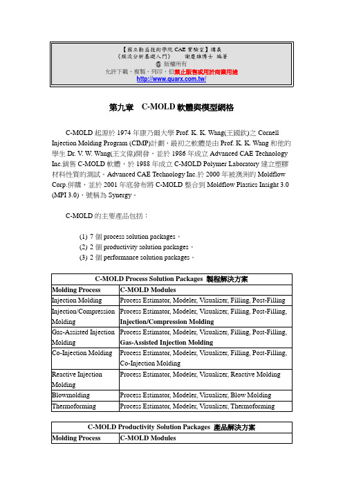
第九章C-MOLD軟體與模型網格C-MOLD起源於1974年康乃爾大學Prof. K. K. Wang(王國欽)之Cornell Injection Molding Program (CIMP)計劃,最初之軟體是由Prof. K. K. Wang和他的學生Dr. V. W. Wang(王文偉)開發,並於1986年成立Advanced CAE Technology Inc.銷售C-MOLD軟體,於1988年成立C-MOLD Polymer Laboratory建立塑膠材料性質的測試。
Advanced CAE Technology Inc.於2000年被澳洲的Moldflow Corp.併購,並於2001年底發布將C-MOLD整合到Moldflow Plastics Insight 3.0 (MPI 3.0),號稱為Synergy。
C-MOLD的主要產品包括:(1)7個process solution packages,(2)2個productivity solution packages,(3)2個performance solution packages。
C-MOLD之Process Solution整合模組以提供元件和模具設計的基礎,提供功能包括:✁防止短射✁平衡流動✁評估縫合線位置✁評估設置澆口位置✁流道尺寸最佳化✁設定排氣孔位置✁設計導流器與限流器✁射出壓力最小化✁評估需求之鎖模力✁螺桿速度曲線最佳化C-MOLD之Productivity Solution整合Process Solution之功能和冷卻模擬,提供:✁冷卻系統對於元件和模具的影響之視覺效果。
✁改變參數以獲得最佳的冷卻條件。
C-MOLD之Performance Solution擴充Productivity Solution的功能,進一步提供:✁纖維配向性(fiber orientation)。
✁凝固應力(Frozen-in stresses)。
培米漫数据表 G6125CS说明书

G6125CS•••••Type overviewType DN G6125CS125Technical dataFunctional dataValve size [mm]5" [125]Fluidchilled or hot water, up to 60% glycol, steam Fluid Temp Range (water)32...350°F [0...176°C]Fluid Temp Range (steam)32...338°F [0...170°C]Body Pressure Rating ANSI Class 125, up to 175 psi below 150°F Flow characteristic equal percentageServicing repack/rebuild kits available Rangeability Sv100:1Max Differential Pressure (Steam)50 psi [345 kPa]Flow Pattern 2-way Leakage rateANSI Class III Controllable flow range stem up - open A – AB Cv263Maximum Inlet Pressure (Steam)100 psi [690 kPa]MaterialsValve body Cast iron - ASTM A126 Class B Valve plug Stainless steel Stem 316 stainless steel Stem seal NLP EPDM (no lip packing)SeatStainless steel AISI 316Pipe connection125 lb flanged Suitable actuatorsNon-Spring EVB(X)Spring(2*AFB(X))Electrical fail-safeAVKB(X)Safety notesWARNING: This product can expose you to lead which is known to the State of California to cause cancer and reproductive harm. For more information go to The valve has been designed for use in stationary heating, ventilation and air-conditioning systems and must not be used outside the specified field of application, especially in aircraft or in any other airborne means of transport.Only authorized specialists may carry out installation. All applicable legal or institutional installation regulations must be complied during installation.The valve does not contain any parts that can be replaced or repaired by the user.When determining the flow rate characteristic of controlled devices, the recognised directives must be observed.G6125CS DimensionsType DN WeightG6125CS125147.74 lb [67 kg]EVB, EVX, RVB, RVXA B C D E F Number of Bolt Holes15.7" [400]15.1" [383]25.4" [646]17.5" [445]5.0" [127]5.0" [127]82*AFB, 2*AFXA B C D E F Number of Bolt Holes15.1" [383]15.7" [400]28.7" [730]21.0" [533]5.0" [127]5.3" [135]8AVKB, AVKXA B C D E F Number of Bolt Holes15.1" [383]15.7" [400]25.4" [646]17.5" [445]5.0" [127]5.0" [127]8EVX24-MFTModulating, Non-Spring Return, Linear, 24 V,Multi-Function Technology®Technical dataElectrical dataNominal voltageAC/DC 24 V Nominal voltage frequency 50/60 HzNominal voltage rangeAC 19.2...28.8 V / DC 21.6...28.8 V Power consumption in operation 5 W Power consumption in rest position 1.5 W Transformer sizing 7.5 VAElectrical Connection 18 GA plenum cable, 1 m, with 1/2" conduit connector, degree of protection NEMA 2 / IP54Overload Protection electronic throughout full stroke Electrical Protectionactuators are double insulated Functional dataActuating force motor 2500 N [560 lbf]Operating range Y 2...10 VOperating range Y note 4...20 mA w/ ZG-R01 (500 Ω, 1/4 W resistor)Input Impedance100 kΩ for 2...10 V (0.1 mA), 500 Ω for 4...20 mA, 1500 Ω for PWM, On/Off and Floating point Operating range Y variable Start point 0.5...30 V End point 2.5...32 VOperating modes optional variable (VDC, PWM, on/off, floating point)Position feedback U 2...10 V Position feedback U note Max. 0.5 mA Position feedback U variable VDC variableDirection of motion motor selectable with switch 0/1Manual override 5 mm hex crank (3/16" Allen), supplied Stroke2" [50 mm]Running Time (Motor)90 s /Running time motor variable 90...150 s Noise level, motor 60 dB(A)Position indicationMechanically, with pointer Safety dataPower source ULClass 2 Supply Degree of protection IEC/EN IP54Degree of protection NEMA/UL NEMA 2Enclosure UL Enclosure Type 2Agency ListingcULus acc. to UL60730-1A/-2-14, CAN/CSA E60730-1:02CE acc. to 2014/30/EU and 2014/35/EU Quality Standard ISO 9001UL 2043 CompliantSuitable for use in air plenums per Section 300.22(C) of the NEC and Section 602 of the IMCAmbient humidityMax. 95% RH, non-condensingEVX24-MFTFootnotesSafety dataAmbient temperature -22...122°F [-30...50°C]Storage temperature -40...176°F [-40...80°C]Servicingmaintenance-free Weight Weight5.73 lb [2.6 kg]MaterialsHousing material Die cast aluminium and plastic casing† Use flexible metal conduit. Push the listed conduit fitting device over the actuator’s cable to butt against the enclosure. Screw in conduit connector. Jacket the actuators input wiring with listed flexible conduit. Properly terminate the conduit in a suitable junction box. Rated impulse Voltage 800V. Type of action 1. Control pollution degree 3.AccessoriesGatewaysDescriptionType Gateway MP to BACnet MS/TP UK24BAC Gateway MP to Modbus RTU UK24MOD Gateway MP to LonWorksUK24LON Electrical accessoriesDescriptionType Belimo PC-Tool, Software for adjustments and diagnostics MFT-P Auxiliary switch 2 x SPDT for NG GV ActuatorsS2A-GV Service Tool, with ZIP-USB function, for programmable andcommunicative Belimo actuators, VAV controller and HVAC performance devicesZTH USToolsDescriptionTypeConnection cable 10 ft [3 m], A: RJ11 6/4 ZTH EU, B: 3-pin Weidmüller and supply connectionZK4-GEN Service Tool, with ZIP-USB function, for programmable and communicative Belimo actuators, VAV controller and HVAC performance devicesZTH USElectrical installationINSTALLATION NOTESActuators may be connected in parallel. Power consumption and input impedance must beobserved.Actuators may also be powered by DC 24 V.A 500 Ω resistor (ZG-R01) converts the 4...20 mA control signal to 2...10 V.Control signal may be pulsed from either the Hot (Source) or Common (Sink) 24 V line.For triac sink the common connection from the actuator must be connected to the hotconnection of the controller. Contact closures A & B also can be triacs. A & B should both beclosed for the triac source and open for triac sink.Actuators with plenum cable do not have numbers; use color codes instead.Meets cULus requirements without the need of an electrical ground connection.Warning! Live electrical components!During installation, testing, servicing and troubleshooting of this product, it may be necessary to work with live electrical components. Have a qualified licensed electrician or other individual who has been properly trained in handling live electrical components perform these tasks. Failure to follow all electrical safety precautions when exposed to live electrical components could result in death or serious injury.EVX24-MFTWiring diagrams On/OffFloating PointVDC / 4 to 20 mA Override Control Min, Mid, Max Positions。